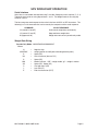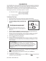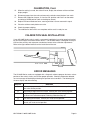
1
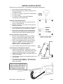
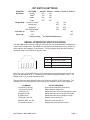
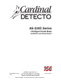
AS-330D Series
Intelligent Scale Base
Installation and Setup Manual
8527-M300-O1 Rev H
11/07
CARDINAL SCALE MFG. CO.
PO BOX 151 v WEBB CITY, MO 64870
PH (417) 673-4631 v FAX (417) 673-5001
Web Site - http://www.detectoscale.com
Technical
Support:
8527-M300-O1
v AS-330D
SeriesPh: 866-254-8261 v [email protected]
Printed in USA
Page 1
8527-M300-O1 v AS-330D Series
Page 2
TABLE OF CONTENTS
Introduction - - - - - - - - - - - - - - - - - - - - - - - - - - - - - - - - - - - - - - - - - - - -
1
Specifications - - - - - - - - - - - - - - - - - - - - - - - - - - - - - - - - - - - - - - - - - -
1
Installation & Setup - - - - - - - - - - - - - - - - - - - - - - - - - - - - - - - - - - - - - -
2
Dip Switch Settings - - - - - - - - - - - - - - - - - - - - - - - - - - - - - - - - - - - - - -
3
Serial Interface Specifications - - - - - - - - - - - - - - - - - - - - - - - - - - - - - - -
3
Scale Weight Data Strings - - - - - - - - - - - - - - - - - - - - - - - - - - - - - - - - -
4
UPS WorldShip Operation - - - - - - - - - - - - - - - - - - - - - - - - - - - - - - - - - -
5
Keypad Functions - - - - - - - - - - - - - - - - - - - - - - - - - - - - - - - - - - - - - - -
6
Annunciators - - - - - - - - - - - - - - - - - - - - - - - - - - - - - - - - - - - - - - - - - - -
6
Calibration - - - - - - - - - - - - - - - - - - - - - - - - - - - - - - - - - - - - - - - - - - - - -
7
Calibration Seal Installation - - - - - - - - - - - - - - - - - - - - - - - - - - - - - - - - -
8
Error Messages - - - - - - - - - - - - - - - - - - - - - - - - - - - - - - - - - - - - - - - - -
8
Care and Maintenance - - - - - - - - - - - - - - - - - - - - - - - - - - - - - - - - - - - -
9
FCC COMPLIANCE STATEMENT
WARNING! This equipment generates uses and can radiate radio frequency and if not
installed and used in accordance with the instruction manual, may cause interference to radio
communications. It has been tested and found to comply with the limits for a Class A
computing device pursuant to Subpart J of Part 15 of FCC rules, which are designed to provide
reasonable protection against such interference when operated in a commercial environment.
Operation of this equipment in a residential area may cause interference in which case the
user will be responsible to take whatever measures necessary to correct the interference.
You may find the booklet "How to Identify and Resolve Radio TV Interference Problems" prepared by the Federal
Communications Commission helpful. It is available from the U.S. Government Printing Office, Washington, D.C.
20402. The stock no. is 001-000-00315-4.
TRADEMARKS
All rights reserved. Reproduction or use, without expressed written permission, of editorial or
pictorial content, in any manner, is prohibited. No patent liability is assumed with respect to
the use of the information contained herein. While every precaution has been taken in the
preparation of this manual, the Seller assumes no responsibility for errors or omissions.
Neither is any liability assumed for damages resulting from use of the information contained
herein. All instructions and diagrams have been checked for accuracy and ease of application;
however, success and safety in working with tools depend to a great extent upon the individual
accuracy, skill and caution. For this reason the Seller is not able to guarantee the result of any
procedure contained herein. Nor can they assume responsibility for any damage to property or
injury to persons occasioned from the procedures. Persons engaging the procedures do so
entirely at their own risk.
Serial Number ______________________
Date of Purchase____________________
Purchased From ____________________
PRECAUTIONS
Before using this instrument, read this
manual and pay special attention to all
"WARNING" symbols:
__________________________________
__________________________________
RETAIN THIS INFORMATION FOR FUTURE USE
8527-M300-O1 v AS-330D Series
IMPORTANT
ELECTRICAL
WARNING
Page 3
8527-M300-O1 v AS-330D Series
Page 4
INTRODUCTION
Thank you for your purchase of our Detecto AS-330D Series Intelligent Scale Base. It was
built with Detecto quality and reliability at our factory in Webb City, Missouri. The AS-330D
Series is equipped with a bi-directional RS-232C compatible port for communication with a
computer. The display is removable and may be mounted on the scale, wall, or counter.
SPECIFICATIONS
Platform Size:
AS-330D - - - - - - - - - - - - - - - - - - 12" x 14", Stainless steel
AS-333D - - - - - - - - - - - - - - - - - - 6" x 10", Stainless steel
AS-334D - - - - - - - - - - - - - - - - - - 6" x 10", Stainless steel
Scale Capacity:
AS-330D - - - - - - - - - - - - - - - - - - 150 lb x 0.05 lb
70 kg x 0.02 kg
150 lb Multi-Interval
0 to 100 lb x 0.5 oz & 100 to 150 lb x 1 oz
AS-333D - - - - - - - - - - - - - - - - - - 17.5 lb x 0.005 lb
7 kg x 0.002 kg
AS-334D - - - - - - - - - - - - - - - - - - 35 lb x 0.01 lb
17.5 kg x 0.005 kg
Load Cell:
AS-330D - - - - - - - - - - - - - - - - - - Cardinal TSP-100kg
AS-333D - - - - - - - - - - - - - - - - - - Cardinal TSP-10kg
AS-334D - - - - - - - - - - - - - - - - - - Cardinal TSP-30kg
Display - - - - - - - - - - - - - - - - - - - - - - - - 6 digit, 7 segment, red LED, 5/8" high
Annunciators - - - - - - - - - - - - - - - - - - - - ZERO, NET, lb, lb-oz, kg
External Controls - - - - - - - - - - - - - - - - - ZERO and TARE keys
Power Requirements - - - - - - - - - - - - - - AC Power adapter - 110/120 VAC to 12 VDC
Operating Temperature - - - - - - - - - - - - 14 to 104 ºF (-10 to +40 ºC)
The AS 330D Series scales are shipped from the factory in the following configuration:
9600 Baud
8 Data Bits
8527-M300-O1 v AS-330D Series
No Parity
1 Stop Bit
Page 1
INSTALLATION & SETUP
Remove the scale from the box. You should have the following components:
¾ Scale Base and Stainless Steel Platform
¾ Display & Display Bracket (already mounted on the
AS-333D/AS-334D)
¾ (2) 10-32 x 1/2" Screws (installed in AS-330D base)
¾ AC Power Adapter
¾ 12 ft. Serial I/O Cable, CPN# 8527-B285-0A
(included with the AS-330D Only)
Install AS-330D Display Bracket
1. Set the scale upside down on a flat level surface,
such as a table or bench.
2. Remove two 10-32 x 1/2" screws from the block on
bottom of scale base.
3. Attach display bracket to scale base by aligning two
holes in bracket with two threaded holes in block.
4. Insert screws (removed in step 2) through holes in
bracket and after checking for clearance between
bracket and side of scale base, tighten securely.
Connect I/O Cables and Level Scale
1. With the scale upside down, connect the display,
serial I/O, and AC power adapter cables to their
respective receptacles on bottom of scale base.
2. Return scale to upright position and adjust feet to
level scale. NOTE! On the AS-330D, the level
bubble is on top of scale base and on the AS333D/AS-334D, it is on the base plate.
3. Place stainless steel platform on top of scale base.
Install Display and Complete Installation
1. Align the two slotted holes in display with the two
screws in display bracket. Slide display over screws
in bracket and gently pull down to secure display.
2. Connect the serial I/O cable to serial port (COM 1 or
COM 2) of computer.
3. Plug AC power adapter into a properly ground 110 to
120 volt outlet.
4. The scale should now come on. With nothing on
scale platform, press ZERO key. The scale should
display zero weight.
Pull
Down
Display Bracket
NOTE! On the AS-333D/AS-334D,
wrap any excess cable from the
display around the two tabs on
the display mounting bracket.
8527-M300-O1 v AS-330D Series
Page 2
DIP SWITCH SETTINGS
FUNCTION
SETTINGS
19,200
9,6001,2
Baud Rate
Switch 1 Switch 2 Switch 3 Switch 4 Switch 5
OFF
ON
4,800
2,400
Weight Mode
ON
ON
ON
OFF
OFF
OFF
Pounds & Ounces
ON
ON
Pounds only
OFF
ON
ON
OFF
OFF
OFF
Kilograms
UPS Pounds Mode2
YES1,2
Auto Zero on
NO
Power Up
1
Factory setting
ON
OFF
2
For UPS WorldShip Users
SERIAL INTERFACE SPECIFICATIONS
Your AS-330D Series scale has a RS-232 serial port that may be connected to a computer for
transmission of weight data. The weight data may be transmitted on demand (on receipt of a
command from the computer) or continuously. The figure below shows the Serial Interface
connector along with the identity of the pins used.
PIN NO.
FUNCTION
1
DATA INPUT (RXD)
4
SIGNAL GROUND (GND)
6
DATA OUTPUT (TXD)
6 5 4 3 2 1
Serial data from the AS-330D Series scale is transmitted and received using 8 data bits, no
parity and one stop bit (8, N, 1). The baud rate may be set using dip switches 1 and 2. The
Weight mode is set using dip switches 3 and 4.
The host computer sends request to the scale in the form of ASCII or HEX characters. The
following is a list of commands that can be sent by the computer and the scale response:
COMMAND
^N (control N, hex 0E)
^O (control O, hex 0F)
~ (tilde, hex 7E)
W (uppercase W)
K (uppercase K)
^X (control X, hex 18)
ESCAPE (ESC, hex 1B)
^D (control D, hex 04)
8527-M300-O1 v AS-330D Series
SCALE RESPONSE
Scale sends weight data continuously
Stop continuous weight data
Weight data sent once in pounds/ounces mode
Weight data sent once in pounds only mode
Weight data sent once in kilograms mode
Zero the scale from the PC
Reset the scale from the PC
Request the scale software revision
Page 3
SCALE WEIGHT DATA STRINGS
AS-330D Pounds/Ounces Mode: SspppbLBbww.wbOZbxccE
Where:
S
s
ppp
b
LB
ww.w
OZ
x
=
=
=
=
=
=
=
=
cc
=
E
=
ASCII STX (HEX 02)
weight sign (space or -)
weight lb, leading zero suppressed
space
the text "LB"
weigh ounces, leading zero suppressed
the text "OZ"
status: M = motion on scale
C = scale over capacity
checksum - these two characters are the ASCII
representation of the computed checksum
ASCII ETX (HEX 03)
Pounds Only Mode:
AS-330D / AS-334D: swwwww.wwxccE
AS-333D: swwwww.wwwxccE
Where:
s
wwwww.ww
=
=
wwwww.www =
x
=
cc
=
E
=
weight sign (space or -)
weight - AS-330D / AS-334D (pounds and 2 position
decimal weight including the decimal point)
weight - AS-333D (pounds and 3 position decimal weight
including the decimal point)
status: M = motion on scale
C = scale over capacity
checksum - these two characters are the ASCII
representation of the computed checksum
ASCII ETX (HEX 03)
Kilograms Mode:
AS-330D: swwwww.wwxccE
AS-333D / AS-334D: swwwww.wwwxccE
Where:
s
wwwww.ww
=
=
wwwww.www =
x
=
cc
=
E
=
weight sign (space or -)
weight - AS-330D (kilograms and 2 position decimal weight
including the decimal point)
weight - AS-330D and AS-334D (kilograms and 3 position
decimal weight including the decimal point)
status: M = motion on scale
C = scale over capacity
checksum - these two characters are the ASCII
representation of the computed checksum
ASCII ETX (HEX 03)
If an internal error occurs, the scale will respond with an error string, SEnccE
Where:
S
E
n
=
=
=
cc
=
E
=
8527-M300-O1 v AS-330D Series
ASCII STX (HEX 02)
the Capital letter "E"
error code number:
1 = invalid calibration
2 = analog failure
4 = attempt to zero outside zero range
5 = non-volatile ram write error
9 = conversion factor error
checksum - these two characters are the ASCII
representation of the computed checksum
ASCII ETX (HEX 03)
Page 4
UPS WORLDSHIP OPERATION
Serial Interface
Serial data is transmitted and received using 7 data bits; Odd parity and 2 stop bits (7, O, 2).
The baud rate may be set using dip switches 1 and 2. The Weight mode is set using dip
switches 3 and 4.
The host computer sends request to the scale in the form of ASCII or HEX characters. The
following is a list of commands that can be sent by the computer and the scale response:
COMMAND
^N (control N, hex 0E)
^O (control O, hex 0F)
W (uppercase W)
SCALE RESPONSE
Scale sends weight data continuously
Stop continuous weight data
Weight data sent once in pounds only mode
Weight Data String
Pounds Only Mode: NXXXXDXXSUUSMMSSCLE
Where:
N
XXXXDXX
S
UU
S
MM
SS
C
L
E
=
=
=
=
=
=
=
=
=
=
Negative sign
weight (pounds and .05 pound including decimal point)
Space (SP)
Unit of measure (the text "LB")
Space (SP)
Motion indicator: “GR” = weight stable, “gr” = weight in motion
Space (SP), Space (SP)
Carriage return (CR)
Last field (LF)
End of transmission (EOT)
8527-M300-O1 v AS-330D Series
Page 5
KEYPAD FUNCTIONS
ZERO KEY
The ZERO key is used to reset the display to zero up to the selected limit of either 4% or
100% of scale capacity. Note that the zero limit is set during setup and calibration of the
scale. This key is also be used to clear the Net weight and return to Gross zero.
TARE KEY
Pressing the TARE key will cause the current gross weight to be stored as the new tare
weight. The display will change to the net weight mode (Net annunciator will turn on).
Tare Operation
1. With the scale display showing 1!! and the ZERO annunciator on, place item (basket,
box, container, etc…) to be tared on scale.
2. Press the TARE key.
3. The display will change to 1!! and the NET annunciator will turn on to show that Net
weight is being displayed. The item's weight has been stored as the "Tare weight".
4. Proceed with the weighing operation.
5. When the commodity and container are removed from the scale, the display will return
to Gross zero
ANNUNCIATORS
The annunciators are turned on to indicate that the scale display is in the mode corresponding
to the annunciator label or that the status indicated by the label is active.
ZERO
This annunciator is turned on to indicate that the weight displayed is within +/- 1/4 division of
the center of zero.
NET
This annunciator is turned on to show that the displayed weight is net weight (Gross weight
less Tare weight. Note that the NET annunciator is only active when a Tare weight is stored.
lb
This annunciator is turned on to indicate that the displayed weight is in pounds.
lb-oz
This annunciator is turned on to indicate that the displayed weight is in pounds and ounces.
kg
This annunciator is turned on to indicate that the displayed weight is in kilograms.
8527-M300-O1 v AS-330D Series
Page 6
CALIBRATION
Your AS-330D Series scale was calibrated at the factory during final inspection and should not
require adjustment. In the event the scale should need re-calibration, the following calibration
procedure should be performed. To maintain the scale’s high degree of accuracy, it is
recommended that a qualified technician with certified test weights re-calibrate the scale.
Before beginning calibration, the following equipment is required:
v
Calibrated test weight (150 lbs or 70 kg for AS-330D)
(15 lbs or 5 kg for AS-333D)
(35 lbs or 15 kg for AS-334D)
v
1/4” slotted screwdriver
To Calibrate The Scale:
1.
Disconnect power from the scale and remove the stainless steel platform.
2.
Remove the 3 screws securing the circuit board enclosure cover and remove the cover.
3.
Locate the Calibration Jumper; J1 and install it on
the center and right pins CAL position (refer to the
diagram).
DO NOT change the J2 jumper setting!
The J2 jumper is for factory use only.
J1
NORM y y y CAL
Normal Operation Position
NORM y y y CAL
Calibration Position
4.
Place the stainless steel platform on the scale.
5.
Apply power to the scale. The scale display will
show [ " ].
6.
Place the appropriate calibrated test weight for your scale and weight mode on the
platform and press the ZERO key (on the remote display).
7.
Starting at the left and advancing right, a series of dashes will appear on the display.
The dashes will stay on the display briefly, then the display will change to [ " ].
8.
Remove the test weight from scale platform.
9.
Press the ZERO key on the remote display.
10.
Starting at the left and advancing right, a series of dashes will appear on the display.
The dashes will stay on the display briefly, then the display will change to [ % ], the
Zero-Limit prompt.
Zero-Limit Feature
[ % ] is the prompt to select whether a 4% limit is placed on the zero
operation (the ZERO key or a command from a computer). By default the
Zero-Limit feature is disabled and the scale can be zeroed up to 100% of the
scale capacity. NOTE! With the zero-limit enabled, any attempt to zero a
weight that is more than 4% of the scale capacity will display the error
message [ ].
11.
If the 100% of scale capacity zero operation is acceptable, press the ZERO key and
hold it for approximately 3 seconds to save it.
12.
If the 4% limit placed on the zero operation is desired, press the ZERO key.
13.
The display will change to [ % ].a
14.
To enable the 4% limit zero operation, press the ZERO key and hold it for approximately
3 seconds to save the new setting.
8527-M300-O1 v AS-330D Series
Page 7
CALIBRATION, Cont.
15.
When the setting is saved, the scale will reset, display the software revision and then
display weight.
16.
Disconnect power from the scale and remove the stainless steel platform from scale.
17.
Remove the Calibration Jumper, J1 from the CAL position and install it on the center
and left pins NORM position (refer to the diagram above).
18.
Replace PC board enclosure cover, securing with the 3 screws removed in step 3.
19.
Place the stainless steel platform on scale.
20.
Check for proper weighing.
21.
The calibration of the scale is now complete and the scale is ready for use.
CALIBRATION SEAL INSTALLATION
If your AS-330D Series scale is used in a commercial application it must be tested and sealed
by your local weights and measurements official. The AS-330D Series is designed to accept a
lead and wire security seal to prevent unauthorized access to the calibration adjustments.
Refer to the figure below for details on the installation of the seal.
ERROR MESSAGES
The AS-330D Series scales are equipped with a diagnostic software program that tests various
portions of the scale’s circuitry and verifies proper operation. Should a problem be detected,
an error message will be displayed alerting the operator to that condition. The following lists
the error display and their meaning:
DISPLAY
MEANING
a
Indicates improper stored calibration data, calibration is necessary. Consult
your scale service provider.
The analog to digital circuit has failed. Consult your scale service provider.
Indicates an attempt to zero a weight outside the scale zero range. Refer to
the Zero-Limit Feature description, following Calibration Step 10.
a
Error writing to NOVRAM. Consult your scale service provider.
The working conversion factor does not match the value stored in NOVRAM.
Consult your scale service provider.
8527-M300-O1 v AS-330D Series
Page 8
CARE AND MAINTENANCE
v
DO NOT subject the scale platform to sudden shocks or impact.
v
DO NOT expose to direct sunlight, temperature extremes or any rapidly moving air source.
v
DO NOT use acetone or other volatile solvents for cleaning the scale.
v
DO NOT submerge the scale in water, pour or spray water directly on it.
v
DO clean the scale with a soft cloth dampened with a mild detergent.
v
DO provide good, safe ground and clean AC power.
v
DO keep the area around the scale clear to provide adequate air circulation.
8527-M300-O1 v AS-330D Series
Page 9
STATEMENT OF LIMITED WARRANTY
Detecto Scale warrants its equipment to be free from defects in
material and workmanship as follows: Detecto warrants to the
original purchaser only that it will repair or replace any part of
equipment which is defective in material or workmanship for a
period of one (1) year from date of shipment. Detecto shall be the
sole judge of what constitutes a defect.
During the first ninety (90) days Detecto may choose to supply all
necessary replacement parts and service during normal weekday
working hours at no charge to the buyer.
After the first ninety (90) days Detecto will supply parts and
service at the job site provided the owner agrees to pay the Dealer
for all travel time, including mileage and test equipment, as well as
any expenses incurred over the direct labor of the technician at the
job site. This limited warranty honors only labor performed by
Detecto authorized dealers.
This warranty does not apply to peripheral equipment not
manufactured by Detecto; this equipment will be covered by certain
manufacturer’s warranty only.
This warranty does not include replacement of expendable or
consumable parts. This does not apply to any item which has
deteriorated or damaged due to wear, accident, misuse, abuse,
improper line voltage, overloading, theft, lightning, fire, water or acts
of God, or due to extended storage or exposure while in purchaser’s
possession. This warranty does not apply to maintenance service.
Purchased parts will have a ninety (90) day repair or replacement
warranty only.
Detecto may require components be returned to the factory; they
must be properly packed and shipping charges prepaid. A return
authorization number must be obtained for all returns and marked
on the outside of all returned packages. Detecto accepts no
responsibility for loss or damage in transit.
8527-M300-O1 v AS-330D Series
Page 10
STATEMENT OF LIMITED WARRANTY
Conditions Which Void Limited Warranty
This warranty shall not apply to equipment which:
A.) Has been tampered with, defaced, mishandled or have had
repairs and modifications not authorized by Detecto.
B.) Has had serial number altered, defaced, or removed.
C.) Has not been grounded according to Detecto’s recommended
procedure.
Freight Carrier Damage
Claims for equipment damaged in transit must be referred to the
freight carrier in accordance with freight carrier regulations.
This warranty sets forth the extent of our liability for breach of any
warranty or deficiency in connection with the sale or use of the
product. Detecto will not be liable for consequential damages of any
nature, including but not limited to, loss of profit, delays or expenses,
whether based on tort or contract. Detecto reserves the right to
incorporate improvements in material and design without notice and
is not obligated to incorporate improvements in equipment
previously manufactured.
The foregoing is in lieu of all other warranties, express or implied
including any warranty that extends beyond the description of the
product including any warranty of merchantability or fitness for a
particular purpose. This warranty covers only those Detecto
products installed in the forty-eight (48) contiguous continental
United States.
Ph. (800) 641-2008
E-mail: [email protected]
203 E. Daugherty
Webb City, MO 64870
8527-M300-O1 v AS-330D Series
02/06
Printed in USA
D268-WARRANTY-DET
Page 11
8527-M300-O1 v AS-330D Series
Page 12