1
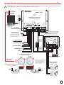
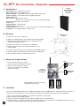
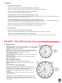
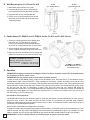
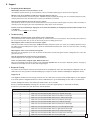
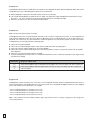
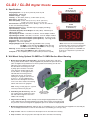
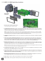
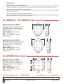
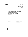
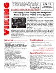
TECHNICAL
Practice
CL Series
Wireless Analog /
Digital Clocks and
Accessories
Practice
TELECOM SOLUTIONS
CTG-2
Master Clock/Tone
Generator (DOD# 463)
FOR THE
CL-RFT
CL-A12
Clock RF
Transmitter/
Repeater
12” Analog Clock
(surface mount
hardware included)
2 1 S T C E N T U RY
October 24, 2013
CL-D2
CL-A16
16” Analog Clock (surface
mount hardware included)
Digital Clock with 2.5”
Numbers (surface or
double mount housing
not included)
CL-D4
Digital Clock with 4”
Numbers (surface or double
mount housing not included)
Viking’s Wireless Clock System provides reliable, accurately synchronized clocks for your entire facility. Eliminating dedicated clock wiring can
save you thousands of dollars on installation and also allows for easy retrofitting of an existing installation. While most wireless systems are
limited to the range of the transmitter, Viking’s system is not. Each clock acts as a Repeater (transceiver), meaning the secondary clocks both
receive and retransmit the signal, maximizing signal transmission distances. The system is comprised of a CTG-2 master clock, a CL-RFT
clock RF transmitter and Analog or Digital wireless slave clocks. Working on Viking’s 915-928MHz frequency hopping technology eliminates
interference with other wireless products and requires no FCC license, eliminating extraneous fees. The received signal remains strong even
under the effects of noise, obstructions or long distances which tend to decrease the signal to noise ratio. Installation is a cinch for our wireless clocks, just insert the batteries or connect power and hang them. That’s it.
Viking’s CL Series wireless clocks include automatic calibration, as well as diagnostics that allow the user to view the signal strength, how long
since the last time the clock received a signal, a comprehensive analysis of the clock itself and remaining battery life. The 12 and 16 inch wireless Analog clocks receive and retransmit an RF clock sync signal every 4 hours (standard mode) or 12 hours (economy mode) allowing for a
battery life of 5 years or 8 years respectively. The 2.5 and 4 inch digital clocks are powered by an included power adapter and receive and
retransmit an RF clock sync
signal every minute. Viking
also offers a complete line of
accessories for the Analog or
Digital clocks such as: double mount housings, wire
CL-DMD2/4
CL-SMD2/4
CL-DMA12/16
Double Mount
Surface Mount
CL-WGD4
CL-WGA12/16
guards and surface mount
Mount Housing
Housing for 2.5”/4”
Housing for 2.5”/4”
Wire Guard for
Wire Guard for 2.5” or
housings (for digital clocks forDouble
12”/16” Analog Clocks
Digital Clocks
Digital Clocks
12”/16” Analog Clocks
4” Digital Clocks
only).
(clocks not included)
(clocks not included)
(clock not included)
Features
CTG-2 Master Clock/ Tone Generator:
CL-A12 and CL-16 Analog Clocks:
• See the complete CTG-2 Technical Practice, DOD# 463
• Built-in repeater receives and retransmits clock sync signal up to 500 ft in
open space
• 915 – 928 MHz frequency-hopping technology
• Internal antenna
• Built-in diagnostic mode for easy maintenance
• 5 yr battery life (standard mode) or 8 yr battery life (economy mode),
(2) “D” cell batteries not included
• Black ABS case and polycarbonate crystal
• Optional double mount housing available (see CL-DMA12/16 on page 6)
CL-RFT Clock RF Data Transmitter/Repeater:
• Transmits the CTG-2 RS485 clock sync data wirelessly to the CL Series
wireless clocks
• Can be configured as a wireless repeater to extend RF transmit range
• Powerful transmission range: Up to 6500 ft in open space
• Compact, slim design makes it versatile for mounting
• Can wirelessly receive and transmit data
• LEDs for indication of transmission and/or receipt of RS485 signal
• Powerful 1 watt (30dBm) transmission
• Works with Viking’s 915 - 928 MHz frequency-hopping technology
• FCC Part 14 compliance (no license required)
CL-D2 and CL-D4 Digital Clocks:
• Built-in repeater receives and retransmits clock sync signal each minute
up to 500 ft in open space
• 915 – 928 MHz frequency-hopping technology
• Internal antenna
• Built-in diagnostic mode for easy maintenance
• Receives the RF Sync signal once a minute
• Immediate correction for time change
• 12 or 24 hour format
• Two (2) levels of adjustable brightness
• Loss of communication alert
• Available in red 2.5″ and 4″ displays
• Surface and double mount housing sold separately
• Optional wire guards (see CL-WGD4 on page 12)
Applications
Using the CTG-2, CL-RFT and CL Series Clocks:
• Wirelessly synchronize all clocks in your facility to the Atomic clock
• Signal the beginning and end of class periods, breaks and lunch periods
for schools
• Signal the beginning and end of shifts, breaks and lunch periods for
factories/businesses
• Provide trigger controlled emergency alert messages for fire, flood, severe
weather, lock down, etc.
• Provide messages at specific times for store sales, promotions, closing
times, airport loading zones, etc.
• Provide Auxiliary contact activation at specific times for specific durations
for controlling lights, cameras, unlocking doors/gates, etc.
Specifications
For complete specifications, see pages 4 - 12.
IF YOU HAVE A PROBLEM WITH A VIKING PRODUCT, PLEASE CONTACT: VIKING TECHNICAL SUPPORT AT (715) 386-8666
Our Technical Support Department is available for assistance Monday through Friday 8am - 5pm central time. So that we can give you better service, before you call please:
1. Know the model number, the serial number and what software version you have (see serial label).
2. Have your Technical Practice in front of you.
3. It is best if you are on site.
RETURNING PRODUCT FOR REPAIR
The following procedure is for equipment that needs repair:
1. Customer must contact Viking's Technical Support Department at 715-386-8666 to obtain a Return Authorization (RA) number. The customer MUST have a complete description of the
problem, with all pertinent information regarding the defect, such as options set, conditions, symptoms, methods to duplicate problem, frequency of failure, etc.
2. Packing: Return equipment in original box or in proper packing so that damage will not occur while in transit. Static sensitive equipment such as a circuit board should be in an antistatic bag, sandwiched between foam and individually boxed. All equipment should be wrapped to avoid packing material lodging in or sticking to the equipment. Include ALL parts of
the equipment. C.O.D. or freight collect shipments cannot be accepted. Ship cartons prepaid to: Viking Electronics, 1531 Industrial Street, Hudson, WI 54016
3. Return shipping address: Be sure to include your return shipping address inside the box. We cannot ship to a PO Box.
4. RA number on carton: In large printing, write the R.A. number on the outside of each carton being returned.
RETURNING PRODUCT FOR EXCHANGE
The following procedure is for equipment that has failed out-of-box (within 10 days of purchase):
1. Customer must contact Viking’s Technical Support at 715-386-8666 to determine possible causes for the problem. The customer MUST be able to step through recommended tests for
diagnosis.
2. If the Technical Support Product Specialist determines that the equipment is defective based on the customer's input and troubleshooting, a Return Authorization (R.A.) number will be
issued. This number is valid for fourteen (14) calendar days from the date of issue.
3. After obtaining the R.A. number, return the approved equipment to your distributor, referencing the R.A. number. Your distributor will then replace the product over the counter at no
charge. The distributor will then return the product to Viking using the same R.A. number.
4. The distributor will NOT exchange this product without first obtaining the R.A. number from you. If you haven't followed the steps listed in 1, 2 and 3, be aware that you
will have to pay a restocking charge.
LIMITED WARRANTY
Viking warrants its products to be free from defects in the workmanship or materials, under normal use and service, for a period of one year from the date of purchase from any
authorized Viking distributor or 18 months from the date manufactured, which ever is greater. If at any time during the warranty period, the product is deemed defective or malfunctions,
return the product to Viking Electronics, Inc., 1531 Industrial Street, Hudson, WI., 54016. Customer must contact Viking's Technical Support Department at 715-386-8666 to obtain a
Return Authorization (R.A.) number.
This warranty does not cover any damage to the product due to lightning, over voltage, under voltage, accident, misuse, abuse, negligence or any damage caused by use of the
product by the purchaser or others. This warranty does not cover non-EWP products that have been exposed to wet or corrosive environments.
NO OTHER WARRANTIES. VIKING MAKES NO WARRANTIES RELATING TO ITS PRODUCTS OTHER THAN AS DESCRIBED ABOVE AND DISCLAIMS ANY EXPRESS OR
IMPLIED WARRANTIES OR MERCHANTABILITY OR FITNESS FOR ANY PARTICULAR PURPOSE.
EXCLUSION OF CONSEQUENTIAL DAMAGES. VIKING SHALL NOT, UNDER ANY CIRCUMSTANCES, BE LIABLE TO PURCHASER, OR ANY OTHER PARTY, FOR CONSEQUENTIAL, INCIDENTAL, SPECIAL OR EXEMPLARY DAMAGES ARISING OUT OF OR RELATED TO THE SALE OR USE OF THE PRODUCT SOLD HEREUNDER.
EXCLUSIVE REMEDY AND LIMITATION OF LIABILITY. WHETHER IN AN ACTION BASED ON CONTRACT, TORT (INCLUDING NEGLIGENCE OR STRICT LIABILITY) OR ANY
OTHER LEGAL THEORY, ANY LIABILITY OF VIKING SHALL BE LIMITED TO REPAIR OR REPLACEMENT OF THE PRODUCT, OR AT VIKING'S OPTION, REFUND OF THE PURCHASE PRICE AS THE EXCLUSIVE REMEDY AND ANY LIABILITY OF VIKING SHALL BE SO LIMITED.
IT IS EXPRESSLY UNDERSTOOD AND AGREED THAT EACH AND EVERY PROVISION OF THIS AGREEMENT WHICH PROVIDES FOR DISCLAIMER OF WARRANTIES,
EXCLUSION OF CONSEQUENTIAL DAMAGES, AND EXCLUSIVE REMEDY AND LIMITATION OF LIABILITY, ARE SEVERABLE FROM ANY OTHER PROVISION AND EACH PROVISION IS A SEPARABLE AND INDEPENDENT ELEMENT OF RISK ALLOCATION AND IS INTENDED TO BE ENFORCED AS SUCH.
FCC
This equipment has been tested and found to comply with the limits for a Class B digital device, pursuant to Part 15 of the FCC rules.
These limits are designed to provide reasonable protection against harmful interference in a commercial installation. This equipment generates, uses and can radiate radio frequency energy and, if not installed and used in accordance with the instructions, may cause harmful interference to radio communications. However, there is no guarantee that interference will not occur in a particular installation. If this
equipment does cause harmful interference to radio or television reception, which can be determined by turning the equipment off and
on, the user is encouraged to try to correct the interference by one or more of the following measures:
a) Reorient or relocate the receiving antenna.
b) Increase the separation between the equipment and receiver.
c) Connect the equipment to an outlet on a circuit different from which the receiver is connected.
d) Consult the dealer or an experienced radio/TV technician.
FCC WARNING
Modifications not expressly approved by the manufacturer could void the user authority to operate the equipment under FCC Rules.
Note: For precautionary measures, FCC recommends a distance of 10cm from the clock to constant human physical exposure.
2
Installation
IMPORTANT: Electronic devices are susceptible to lightning and power station electrical surges from both the AC outlet and the telephone line.
It is recommended that a surge protector be installed to protect against such surges.
CL-RFT
(Clock RF Data
Transmitter/
Repeater)
VIKING ©
MODEL CTG-2
VIKING
ELECTRONICS
HUDSON, WI 54016
120V AC
(AC Cord
Included)
FORCE TIME SYNC
SET SCHEDULE
SET TIME
- + - +
18 19 20 21
P.M.
- + - +
1 2 3 4 5 6 7 8 9 1 0 11 1 2 13 14 15 16 17
RUN
AUDIO
OUTPUT
AUDIO
INPUT
PAGE TRIGGER
12VDC OUTPUT
SPEAKER
OUTPUT
PAGE TRIGGER
CONTACTS
TRIGGER
INPUT 4
TRIGGER
INPUT 3
N.C.
RS485 A B
Input
TRIGGER
INPUT 2
White
TRIGGER
INPUT 1
USB
PROGRAMMING
PORT
PHONE LINE
INPUT
Black
Green
N.0.
PWR 13.8 VAC
ADVANCED CLOCK CONTROLLED
TONE / MESSAGE GENERATOR
COM
AB
(Up to 4000 ft)
Adjust master volume to match
paging level from phone system.
CO Line or Analog
PABX/KSU Station
(optional: for Atomic clock
sync and/or remote touch
tone schedule changes, etc.)
Paging Amplifier (PA-30 shown,
not included - see DOD# 489)
VIKING ©
MODEL PA-30
MASTER
VOLUME
2
3 4
5
6
7
8
LED2
NIGHT
TRANSFER
CONTACT
CLOSURE
PAGE
CONTACT
LINE IN
PAGE IN
AUX IN
SPKRS
SPKRS
1
MAX
LOUD RINGING
70V OUT
Evacuation Signal
MIN
30 WATT TELECOM
PAGING AMPLIFIER
600 OHM
OUTPUT
Paging Port
Output of
PABX/KSU
Trigger Examples:
PWR 15 VAC
VIKING
ELECTRONICS
HUDSON, WI 54016
9 10 11 12 13 14 15 16 17
LED3
LED4
LED5
C
C
C
C
Lock Down Message
BACKGROUND
MUSIC IN
!
on
C
LED1
Page Contact
Output
(optional but
recommended)
Severe Weather
+ SPKR - + SPKR 70V OUT
1
600 OHM
OUTPUT
AUX IN
PAGE IN
2
3
4
PAGE
CONTACT
RINGING
LINE
CC
NT
1/8" mono
plug
All Clear
Viking RF Synchronized Clocks
with Built-In Repeaters
CL-A16
CL-A12
*
(Up to 6500 ft
in open space)
* Note: Each clock's repeater will
re-transmit the clock sync signal
up to 500 ft in open space. For
longer distances, a CL-RFT can
be set up as a repeater for up to
6500 ft in open space.
and / or
** Note: The gel-filled (water tight) butt connectors
are designed for insulation desplacement. Do not
strip wires prior to terminating.
Positive
Negative
Paging Horns and/or
Ceiling Speakers
30AE
*
*
120V AC
12V DC
Adapter
(included)
Optional Background Music
Source (not included)
*
25AE
120V AC
(+) Red with
Black stripe
(-) Black with
White stripe
** Gel-Filled Butt Connectors (included)
Note: Polarity Sensitive!
CL-D2
CL-D4
(+) Red with
Black stripe
(-) Black with
White stripe
13.8V AC
Adapter
(included)
(+) Black
and / or
(-) Black with
White stripe
* Gel-Filled Butt Connectors
(included) Note: Polarity Sensitive!
30AE
25AE
3
C L - R F T R F Tr a n s m i t t e r / R e p e a t e r
CL-RFT
(Clock RF Data
Transmitter/
Repeater)
A. Specifications
Input Voltage: 90 - 230 Volts AC, 50 - 60 Hz
Input: RS485 (from Viking model CTG-2)
RF Power Output: 1 watt (30dBm). Transmits up to 6500 ft in open space
Frequency Range: 915-928 MHz frequency hopping technology
Mount: Wall mount
Environmental: Operating: 0°C to 50°C
Storage: -15°C to 70°C with 5% to 95% non-condensing humidity
Housing: Smooth surface metal enclosure
Color: Black
Shipping Weight: 4.9 lbs (2.22 kg)
Antenna Length: 7” (17.78cm)
Housing Dimensions: 11” x 8” x 1.7” (27.94cm x 20.32cm x 4.32cm) (with bottom cover)
Compliance: FCC compliant, part 15, section 15,247
B. Mounting
Rear View of
CL-RFT
1. Remove the cover of the wiring panel.
2. Mark the four drilling points on the wall based on the drawing (right).
3. Drill the holes for the anchors supplied in the mounting kit at the
designated markings from step 1.
4. Install the four anchors in the holes that were just drilled.
5. Install the first two screws in the top holes leaving 1/8” of the
thread exposed.
6. Line up the top key slots over the screws and lock the CL-RFT into place.
7. Install the bottom screws through the wiring access panel and tighten.
8. After all wiring is complete, re-install the panel cover.
C. Wiring and Jumper Settings
JP2
1. Remove bottom chassis cover to gain
access to the power and RS485 connections.
JP1
CL-RFT
(Clock RF Data
Transmitter)
Transmitter
Repeater
RS485
D. Installation
L1 Hot
Wht Grn Blk
Ground
Note: 14 AWG is the smallest conductor
acceptable for power input.
Input A
Input B
Output B
Output A
10 9 8 7
L2 Neutral
2. Remove the top chassis cover to gain
access to JP1 and JP2 (RF Transmitter/
Repeater selections).
Transmitter
Repeater
[email protected]
100-240V AC
50-60 Hz
There is a main CL-RFT Transmitter in the building with optional repeaters (CL-RFT with JP1 and JP2 in “Repeater” position, see
section C above) as needed to cover the entire premise. Repeaters are synchronized wirelessly to the main transmitter.
1.
2.
3.
4.
4
Place the main transmitter (CL-RFT) in a central location (hallway recommended).
Pick the location of the optional repeaters.
Place the repeaters in a location where the signal is available from the main transmitter.
Repeat the above mentioned steps with the corresponding repeaters. Please note that the corresponding repeaters can receive
a signal from another repeater, and not only from the main transmitter.
D. Support
1. Frequently Asked Questions
Where is the best location for the Transmitter/Repeater to be mounted?
Usually, the hallway is the best location because it is mostly open space in typical applications.
How far can the Transmitter/Repeater transmit the wireless signal?
The Transceiver can transmit up to 6500 ft in open space.
Can analog wireless clocks be combined with digital wireless clocks?
Absolutely. The analog and digital wireless clocks are designed to work together, whether the clocks are running on battery (analog wireless clock only), or 24 volts (digital clocks only).
Will the Transmitter/Repeater have interference from cordless or cellular phones?
No, because with Viking’s innovative frequency-hopping technology, interference will not occur. The repeater switches frequencies automatically when the receiver and transmitter is open, thus interference is avoided.
My power source is 220 volts. Can the Transmitter/Repeater be powered on that voltage?
Yes, the Transmitter/Repeater can work on 110 volts/50-60 Hz or 220 volts/50-60 Hz.
2. Troubleshooting
The clocks aren’t receiving the signal. What should I do?
Make sure that the Transmitter/Repeater is in a place where the signal can be transmitted in open space.
What should I do if the Transmitter/Repeater is not powering up?
Measure the voltage between pins L1 & L2. The voltmeter should read 90 - 230 VAC between the hot and the neutral.
CL-A12 / CL-A16 Analog Clocks
A. Specifications
CL-A12 Clock Size: 12.65” (32.13cm) outer diameter, 2.18” (5.54cm) depth
CL-A16 Clock Size: 16.65” (42.29cm) outer diameter, 2.18” (5.54cm) depth
Time Base: Quartz automatic calibration
Battery Life: 5 years (normal mode), 8 years (economy mode) using (2)
Duracell Procell “D” Batteries (not included). Note: Standard alkaline batteries can be used but will have a slightly shorter battery life.
Input Sensitivity: -103 dbm
Transmitter (Repeater) Power Output: 1/4 watt (8 dbm). Transmits up to
500 ft in open space.
Operating Sensitivity: 915-928 MHz frequency hopping technology
Color: Standard black
Dial: Durable polystyrene material
Case: Smooth surface ABS case
Crystal: Shatterproof, side molded polycarbonate crystal
*
Movement Dimensions: 7.32” x 3.46” x 1.81” (18.59cm x 8.79cm x
4.6cm)
Shipping Weight: CL-A12: 2.9 lbs (1.32 kg)
CL-A16: 4.5 lbs (2.04 kg)
Mounting Kit Includes: (2) plastic anchors, (2) 10 x 1.5 sheet metal
screws, (1) 4mm threaded 10mm length screw (attached to bracket), (1)
mounting bracket, (1) knurled nut, (1) battery cover screw
Compliance: FCC compliant, part 15, section 15,247 (no license
required)
Environmental: 0° C to 32° C (32° F to 90° F) with 5% to 95% noncondensing humidity
* Note: Each clock has a built-in Repeater (Transceiver) which receives
and retransmits the clock sync signal up to 500 ft in open space. For
longer distances, a CL-RFT can be set up as a repeater for up to 6500 ft
in open space.
*
*
CL-A12
(12” Analog
Clock)
*
CL-A16
(16” Analog
Clock)
5
B. Wall Mounting the CL-A12 and CL-A16
1. Mount both plastic anchors in the wall.
CL-A12
(12” Analog Clock)
CL-A16
(16” Analog Clock)
2. Insert the sheet metal screws (#10) through
the mounting bracket into the plastic anchors.
3. Hang the clock on the mounting bracket.
4. Put the screw (4mm) through the hole on the
top of the clock into the hole at the top of the
mounting bracket.
C. Double Mount CL-DMA12 and CL-DMA16 for the CL-A12 and CL-A16 Clocks
1. Screw the mounting bracket to the double gang
box using four (4) inner holes on mounting
bracket, or mount the mounting bracket directly
to the wall or ceiling using the four (4) outer holes.
2. Secure hanging rod to mounting bracket with
screws supplied, and place cover over connection.
3. Place the clocks on the double mount housing and
tighten the screws to secure clocks as shown right.
CL-DMA12 / CL-DMA16 Specifications
Housing: Black powder coated steel
Shipping Weight: CL-DMA12: 6.1 lbs (2.27 kg)
CL-DMA16: 7.4 lbs (3.36 kg)
CL-DMA12 / CL-DMA16
(Double Mount for 12” and
16” Analog Clocks)
D. Operation
IMPORTANT: We highly recommend installing the CTG-2 Clock/Tone Controller and CL-RFT Transmitter before
the installation of the CL Series clocks.
IMPORTANT: Remove pin from back of clock before installing batteries.
In order to install the CL-A12/16 clocks, simply remove the battery cover, and install two (2) D cell batteries (recommended battery type: Duracell PROCELL). After installation of the battery, replace the battery cover and the clock
should start correcting within five (5) minutes. If the clock does not automatically correct itself, then manually press the
Transmit/Receive switch once on the clock closest to the clock that isn’t working. The second hand will go to 8 notifying the user that the clock is transmitting a signal. Then go to the clock that isn’t working and press the
Transmit/Receive switch twice. The second hand will go to 4 notifying the user it is looking for a signal. This should get
the signal to the clock. Note: The Transmit/Receive signal window is 10 minutes and multiple clocks can receive from
the transmitting clock during that period.
Normal Mode / Economy Mode
The CL-A12/16 clocks have two different modes in which they will operate. Normal mode allows the clock to transmit/receive every 4 hours. This mode will allow the clock to have a 5 year battery life (provided good reception).
Economical mode allows the clock to transmit/receive every 12 hours. This mode will allow the clock to have up to a 8
year battery life (provided good reception).
Normal mode is defaulted when shipped from the factory.
To toggle this mode, push and release the Diagnostic Switch and the Transmit/Receive switch simultaneously. If 5 year
mode is selected, the LED will be solid RED for two minutes and the second hand will go to 5 (25 seconds). If 8 year
mode is selected, the LED will be solid GREEN for two minutes and the second hand will go to 8 (40 seconds).
6
IMPORTANT: If a clock is being added to an existing system, it must be in normal mode.
E. Support
1. Frequently Asked Questions
What battery size do I use for the wireless clock?
The batteries required are two (2) “D” cell batteries. The recommended battery type is “Duracell: Procell [D] size”.
Will the clock cause interference with any of my other wireless devices?
No, the CL Series wireless clock works on 915 - 928 MHz frequency-hopping technology. The clock switches frequencies automatically when the receiver and transceiver is open, thus interference is avoided.
How long does it take for the clock to receive a signal?
Upon power up of the clock, the receiver will be turned on for ten (10) minutes until the signal is acquired. If the user wishes to
manually look for the signal, press the Transmit/Receive switch twice on the movement.
Can the clocks be set manually to display the correct time at installation (as a temporary measure until the master clock
is installed)?
CL Series clocks can NOT be set manually.
2. Troubleshooting
What happens if I power up the clock and the clock is not moving?
The clock should move at normal speed upon power up. If it does not move at normal speed, check the battery and make sure
the clock receives power. Also, be sure to remove the pin prior to starting up the clock.
What happens if the clock does not receive the signal?
Take the clock within close proximity to the CL-RFT Transmitter and power up the clock. If the clock is battery operated, remove
the battery and put the battery back in again or press the Transmit/Receive button twice. If the clock does not correct, call Viking
technical support.
What happens if the clock shows the wrong time?
Move the clock to Diagnostic #1 in order to find the last time that it received the signal. Perform a Diagnostic #3 to check the
gears for the clock.
How do you know if the clock receives a good signal?
Perform Diagnostic #2. See page 8 for detailed instructions.
I have a location with a marginal signal. What should I do?
Move your Transmitter closer to the location or add a Repeater (CL-RFT with JP1 and JP2 in “Repeater” position, see page 4)
between the Transmitter and the location with marginal signal.
3. Diagnostic Testing
The number of times that the switch is pressed will determine the diagnostic mode. After determining the diagnostic mode, the
LED between the two (2) switches will start flashing a green light. The number of flashes will display the diagnostic number.
Diagnostic #1
This diagnostic will determine how long (# of hours) since the clock last received the communication signal. To enter diagnostic #1 mode, push the Diagnostic Switch once which is indicated by the green LED flashing one time with a 2 second break.
A. While in diagnostic modes, hour and minute hands continue to run normally.
B. The second hand will display how long since the clock received time signal (please see below table for details).
C. After three (3) minutes, the clock will resume normal operation.
Second Hand Position
Time Since Clock Last Received a Communication Signal
12
Clock has received communication in the past hour
1
Clock has received communication between one and two hours ago
2
Clock has received communication between two and three hours ago
3
Clock has received communication between three and four hours ago
4
Clock has received communication between four and five hours ago
5
Clock has received communication between five and six hours ago
6
Clock has received communication between six and seven hours ago
7
Clock has received communication between seven and eight hours ago
8
Clock has received communication between eight and nine hours ago
9
Clock has received communication between nine and ten hours ago
10
Clock has received communication between ten and eleven hours ago
11
Clock has received communication over eleven hours ago
7
Diagnostic #2
This diagnostic will determine the quality of the time signal. To enter Diagnostic #2 mode, push the Diagnostic Switch twice which
is indicated by the green LED flashing twice with a two (2) second break.
A. While in diagnostic modes, hour and minute hands continue to run normally.
B. The second hand will display the quality of the time signal. (The signal percentage is displayed on the dial of the clock. It
goes from 1 – 10, with 1 being the best signal strength and 10 being the least signal strength.
C. After three (3) minutes, the clock will resume normal operation.
Diagnostic #3
Note: This test takes approximately 10 minutes.
This diagnostic will test the mechanical portion and some of the electronic components of the clock. To enter Diagnostic #3
mode, push the Diagnostic Switch three times which is indicated by the green LED flashing three (3) times with a two (2) second break. If an error occurs, the clock will flash the red LED to signal the error code number (please see table below). While
in Diagnostic #3, the clock will perform the following steps:
A.
B.
C.
D.
Clock moves second hand to 00.
Clock moves second hand again to 00, to verify that the hands arrived after sixty (60) pulses.
Clock moves minute and hour hands to the next known position.
Clock moves minute and hour hands again to the same known position in order to verify that the hands reach the position
after 720 pulses.
E. Clock moves the hour and minute hands to 12:00:00.
F. Press the Transmit/Receive button twice. The second hand should move to the 4 until it has acquired the clock signal or until
10 minutes has elapsed.
Number of
Red Flashes
1,2
3,4,5
6
Diagnosis of Error Code
Clock detected problem with second hand. Check hands to see if they are hitting each other. Repeat test.
Clock detected problem with hour/minute hand. Check to see if they are hitting each other. Repeat test.
Call tech support.
Diagnostic #4
This diagnostic will test the battery level of the clock. To enter Diagnostic #4 mode, push the Diagnostic Switch four (4) times
which is indicated by the LED flashing four times every two seconds. The second hand will display the battery level by stopping
at one of the numbers on the clock’s face. For example:
•
•
•
•
If
If
If
If
the
the
the
the
second
second
second
second
hand
hand
hand
hand
lands
lands
lands
lands
on
on
on
on
7, the battery level is 2.7V.
8, the battery level is 2.8V.
9, the battery level is 2.9V.
10, the battery level is 3V.
Note: Clock operation becomes unstable if battery output drops below 2.7V DC, so running a diagnostic at this voltage may
cause erratic behavior.
8
CL-D2 / CL-D4 Digital Clocks
CL-D2
A. Specifications
Display Digit Size: 2.5” (6.35 cm) and 4.0” (10.16 cm) tall
Display Color: Vibrant Red
Number of Digits: 4 digits
Visibility: CL-D2: 100 ft. (30.48 m), CL-D4: 250 ft. (76.2 m)
Bezel Color: Anti-glare red
Bezel Size (HxW): CL-D2: 4.69” (11.91 cm) x 10.31” (26.19 cm)
CL-D4: 6.75” (17.15 cm) x 13.31” (33.8 cm)
Environmental: Operating: 0°C to 45°C, Storage: -15°C to 75°C with 5%
to 95% non-condensing humidity
Operating Frequency: 915 - 928 MHz frequency-hopping technology
Input Sensitivity: -103 dBm
Transmitter (Repeater) Power Output: 1/4 watt (8 dbm). Transmits up to
500 ft in open space.
Input Voltage for CL-D2: 12-30 VDC, 12-30 VAC. 12V DC adapter included
Input Voltage for CL-D4: 16-28 VDC, 14-28 VAC. 13.8V AC adapter included
CL-D2 Average Current Consumption (max brightness): 85 mA @ 24 VAC
CL-D4 Average Current Consumption (max brightness): 190 mA @ 24VAC
Display Format: 12 or 24 hour mode
Brightness: Two levels, adjustable
Shipping Weight: CL-D2: 2.0 lbs (0.91 kg), CL-D4: 3.5 lbs (1.59 kg)
CL-SMD2: 1.3 lbs (0.59 kg), CL-SMD4: 2.0 lbs (0.91 kg)
CL-DMD2: 4.2 lbs (1.91 kg), CL-DMD4: 6.1 lbs (2.77 kg)
Mounting: Surface Mount (see CL-SMD2/4 below) or
Double Mount (CL-DMD2/4 on page 10) housing required
Compliance: FCC compliant, part 15, section 15,247 (no license required)
(Digital Clock with
2.5” Tall Numbers)
*
*
CL-D4
*
(Digital Clock with
4” Tall Numbers)
*
* Note: Each clock has a built-in Repeater
(Transceiver) which receives and retransmits
the clock sync signal up to 500 ft in open
space. For longer distances, a CL-RFT can
be set up as a repeater for up to 6500 ft in
open space.
B. Wall Mount Using Optional CL-SMD2 or CL-SMD4 Surface Mount Housing
1. Mount Housing to Wall and/or Gang Box - To mount the housing to the wall, drive
two (2) plastic anchors into the wall (not supplied in kit) and take two pan head screws
(also not supplied in kit) and drive them into the plastic inserts leaving an 1/8th inch
gap between the head of the screw and
the wall. Mount the housing to the wall
by lining up the two holes in the back
of the top of the housing with the two
screws with the 1/8 inch gap from the
wall and slide the housing onto the
heads of the screws. To mount the
housing to the gang box, take the four
(4) 6-32 x 1” screws (supplied in kit)
and screw them through the four holes
in the center of the inside of the housing
and the four holes in the gang box.
Note: If using a metal gang box, a ground
must be provided to the gang box.
2. Feed Wiring Into the Housing - Take the
wire coming from the inside of the gang
box and feed it through the hole in the
middle of the housing.
Single or Double
Gang Electrical Box
(not included)
3. Plug and Secure Wiring - Loosen and slip excess wiring through provided wire clamp
(comes attached to the housing) and tighten the clamp. After securing excess wiring, plug
the jack at the end of the wiring into the appropriate jack on the back of the display board.
4. Mount Display Board to Housing - Using the four (4) self tapping, 6-19 x 1/2” flat head screws supplied in the assembly kit,
take the display board and screw it to the front side of the clock housing (4 screws per clock).
5. Snap on Filter - Take the red filter bezel and snap it on to the front side of the housing.
6. Snap on Frame - Take the gray frame and snap it on to the front side of the housing.
9
C. CL-DMD2 / CL-DMD4 Double Mount Installation
* Single or Double
Gang Electrical Box
(not included)
* Important: Single or Double Gang Electrical Box
Use one that can support a minimum of 50 lbs.
1. Install Metal Mounting Bracket - Screw the metal mounting bracket to the wall or ceiling in which the clock is being installed
using the four (4) 6-32 x1” screws supplied in the assembly kit. Use the inner four holes to mount to the gang box. Use the outer
four holes to mount anchors to the wall (anchors not supplied in kit).
Notes: If using a plastic gang box, a ground wire must be routed through the gang box and into one (1) of the four (4) Metal
Mounting Bracket screws in order to provide ground to the Metal Mounting Bracket. Note: The Metal Mounting Bracket MUST
be secured by both the screws going to the gang box AND the anchors going into the wall.
2. Feed Wiring Through Base and Pole - Take the wire coming from the gang box and feed it through the supplied mounting pole
and base.
3. Snap and Screw Base to Metal Mounting Bracket - With the wire now fed through the base and the pole, snap the base to
the metal mounting bracket by first making contact with the lip in the upper side of the base and the metal mounting bracket.
When the base has been snapped onto the bracket, take the two (2) 6-32 x 1/2" pan head screws supplied in the assembly kit
and screw them into the two holes on the underside of the base to secure the base to the Metal Mounting Bracket.
4. Mount Clock Housings to Pole - Feed the wiring from the end of the mounting pole into the hole in the middle of each clock
housing. Align each housing, one at a time, with the four holes on the mounting pole and screw from the inside of the housing
into the pole using the four (4) 8-32 x 7/16” screws supplied in the assembly kit (4 screws per clock).
Note: End caps from one side of each clock must be removed to mount both clocks to the mounting pole. Remove one end cap
from each clock from the side in which the mounting pole enters the clock.
5. Screw Both Housings Together - Using the two (2) self tapping, 6-19 x 7/16” screws supplied in the assembly kit, screw both
back sides of the clock housings together (2 screws per clock).
6. Plug and Secure Wiring - Loosen and slip excess wiring through provided wire clamp (comes attached to each housing) and
tighten the clamp. After securing excess wiring, plug the jack at the end of the wiring into the appropriate jack on the back of the
display board. Perform this task for both clock housings.
7. Mount Display Board to Housing - Using the four (4) self tapping, 6-19 x 1/2" flat head screws supplied in the assembly kit,
take the display board and screw it to the front side of the clock housing (4 screws per clock).
8. Snap on Filter - Take the red filter bezel and snap it on to the front side of each clock housing.
9. Snap on Frame - Take the gray frame and snap it on to the front side of each clock housing.
10
D. Wiring and Jumper Settings
View of CL-D2/4 Digital Clock Circuit Board
P5
Red
Black
N/C
Orange
Purple
White
N/C
N/C
*AC/DC Power Input
(not used)
Earth Ground
(not used)
*AC/DC Power Input
] ON position
P2
JP1 JP2 JP3
*Note: Power input is not polarity sensitive.
See "Input Voltage" specifications on page 9.
Description
ON (factory default)
OFF
JP1
12/24 hour mode
12 hour mode
24 hour mode
JP2
Brightness
Brightest
Bright
JP3
(not used)
N/A
N/A
Jumper Number
E. Support
1. Frequently Asked Questions
Will the clock cause interference with any of my other wireless devices?
No, the CL-D2/4 series wireless clocks work on 915 - 928 MHz frequency-hopping technology. The clock switches frequencies
automatically when the receiver and transceiver is open, thus interference is avoided.
How long does it take for the clock to receive a signal?
Upon power up, the clock will look for the signal for 30 minutes. The CL-D2/4 series wireless clock will look for the signal every
minute thereafter.
Do the CL-D2/4 wireless clocks work together with CL-A12/16 Series analog wireless clocks?
Yes, the CL-D2/4 wireless clocks work integrally with Viking’s CL-A12/16 series wireless analog clocks.
How many ways can I mount the CL-D2/4 Series clock?
The clock can be mounted in either surface or double mount. Please see pages 9 and 10 for more information on mounting
instructions.
Can the CL-D2/4 digital clocks be used as an independent clock?
No, the CL-D2/4 requires a communication input and must be used with a Viking Transmitter/Repeater (model CL-RFT).
What will happen if the clock is not receiving a signal?
The colon on the display will flash every second.
How can the clock be powered?
The CL-D2 clock is available in 12-30 volt AC/DC model only. The CL-D4 is available in 16-28V DC / 14-28V AC model only.
AC power adapters are provided with each clock.
11
2. Troubleshooting
What happens if the clock doesn’t power up?
Make sure the wiring is correct. The power should be on the orange and yellow wires of the harness. The middle (green) wire
is ground. If the wiring is correct, take a volt meter and measure the voltage. The voltage should be between 14 - 28 volts.
What happens if the clock does not receive the signal?
Take the clock within close proximity to the transmitter and power the clock. If the clock does not correct, call Viking technical
support at (715) 386-8666.
I have a location with a marginal signal. What should I do?
Move your Transmitter closer to the location or add a Repeater (CL-RFT with JP1 and JP2 in “Repeater” position, see page 4)
between the Transmitter and the location with marginal signal.
C L - W G A 1 2 / C L - W G A 1 6 Wire Guards
18.75" Diameter
5.0"
CL-WGA12
(Front View)
CL-WGA12
(Side View)
Specifications for CL-WGA12
Description: Optional wire guard for use with
the Viking CL-A12 12” round analog clock
Dimensions: 18.75” x 16” x 5” (47.63cm x
40.64cm x 12.7cm)
Shipping Weight: 3.9 lbs (1.77 kg)
Wire: 3, 6 and 9 gauge
Finish: Zinc plated epoxy, lacquered
baked clear coat
23" Diameter
5.0"
Specifications for CL-WGA16
Description: Optional wire guard for use with
the Viking CL-A16 16” round analog clock
Dimensions: 23” x 19” x 5” (58.42cm x
48.26cm x 12.7cm)
Shipping Weight: 5.2 lbs (2.36 kg)
Wire: 3, 6 and 9 gauge
Finish: Zinc plated epoxy, lacquered
baked clear coat
CL-WGA16
(Front View)
CL-WGA16
(Side View)
C L - W G D 4 Wire Guard
18.0"
6.5"
Specifications for CL-WGD4
Description: Optional wire guard for use
with the Viking CL-D2 or CL-D4 digital clock
Dimensions: 18” x 15” x 6.5” (45.72cm x
38.10cm x 16.51cm)
Shipping Weight: 4.6 lbs (2.09 kg)
Wire: 3, 6 and 9 gauge
Finish: Zinc plated epoxy, lacquered
baked clear coat
15.0"
CL-WGD4
(Front View)
Product Support Line...715.386.8666
CL-WGD4
(Side View)
Fax Back Line...715.386.4345
Due to the dynamic nature of the product design, the information contained in this document is subject to change without notice. Viking Electronics, and its affiliates and/or subsidiaries
assume no responsibility for errors and omissions contained in this information. Revisions of this document or new editions of it may be issued to incorporate such changes.
12
DOD# 466
Printed in the U.S.A.
ZF303110 Rev C