1
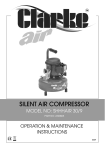
SILENT AIR COMPRESSOR
MODEL NO: SHHHAIR 30
PART NO: 2320860
OPERATION & MAINTENANCE
INSTRUCTIONS
0309
INTRODUCTION
Thank you for purchasing this CLARKE Silent Air Compressor.
Before attempting to use this product, please read this manual thoroughly and
follow the instructions carefully. In doing so you will ensure the safety of yourself
and that of others around you, and you can look forward to your purchase
giving you long and satisfactory service.
GUARANTEE
This product is guaranteed against faulty manufacture for a period of 12
months from the date of purchase. Please keep your receipt which will be
required as proof of purchase.
This guarantee is invalid if the product is found to have been abused or
tampered with in any way, or not used for the purpose for which it was
intended.
Faulty goods should be returned to their place of purchase, no product can
be returned to us without prior permission.
This guarantee does not effect your statutory rights.
PARTS AND SERVICING
For Parts & Servicing, please contact your nearest dealer, or
CLARKE International, on one of the following numbers.
PARTS & SERVICE TEL: 020 8988 7400
PARTS & SERVICE FAX: 020 8558 3622
or e-mail as follows:
PARTS: [email protected]
SERVICE: [email protected]
2
SAFETY PRECAUTIONS
WARNING: AS WITH ALL MACHINERY, THERE ARE CERTAIN HAZARDS
INVOLVED WITH THEIR OPERATION AND USE. EXERCISING RESPECT AND
CAUTION WILL CONSIDERABLY LESSEN THE RISK OF PERSONAL INJURY.
HOWEVER, IF NORMAL SAFETY PRECAUTIONS ARE OVERLOOKED, OR
IGNORED, PERSONAL INJURY TO THE OPERATOR MAY RESULT.
1. Compressed air is dangerous, NEVER direct a jet of air at people or animals, and
NEVER discharge compressed air against the skin.
2. DO NOT operate your compressor with any guards removed.
3. Electrical or mechanical repairs should only be carried out by a qualified engineer. If
problems occur, contact your Clarke dealer.
4. Before carrying out any maintenance, ensure the pressure is expelled from the air
receiver, and the machine is disconnected from the mains supply.
5. DO NOT leave pressure in the receiver overnight, or when transporting.
6. DO NOT adjust, or tamper with the safety valves. The maximum pressure is factory
set, and clearly marked on the machine.
7. DO NOT operate in wet or damp conditions. Keep the machine dry at all times.
Similarly, a clean atmosphere will ensure efficient operation. Do not use in dusty or
otherwise dirty locations.
8. Some of the metal parts can become quite hot during operation. Take care not to
touch these until the machine has cooled down.
9. Always adjust the pressure regulator to the recommended setting for the particular
spray gun or tool being used.
10. When spraying flammable materials e.g. cellulose paint, ensure that there is
adequate ventilation and keep clear of any possible source of ignition.
11. Protect yourself. Think carefully about any potential hazards which may be created
by using the air compressor and use the appropriate protection. e.g. Goggles will
protect your eyes from flying particles. Face masks will protect you against paint
spray and/or fumes.
12. Before spraying any material always consult paint manufacturers instructions for
safety and usage.
13. Do not exert any strain on electrical cables and ensure that air hoses are not angled
or wrapped around machinery etc.
14. When disconnecting air hoses or other equipment from your compressor ensure that
the air supply is turned off at the machine outlet and vent all pressurised air from
within the machine and other equipment attached to it.
15. Make sure that children and animals are kept well away from the compressor and
any equipment attached to it.
16. Always ensure that all individuals using the compressor have read and fully
understand these Operating Instructions.
17. Ensure that any equipment or tool used in conjunction with your compressor, has a
safety working pressure exceeding that of the machine.
3
ELECTRICAL CONNECTIONS
Connect the mains lead to a standard, 230 Volt (50Hz) electrical supply
through an approved 13 amp BS 1363 plug, or a suitably fused isolator switch.
WARNING: THIS APPLIANCE MUST BE EARTHED
IMPORTANT: The wires in the mains lead are coloured in accordance with the
following code:
Green & Yellow
Blue
-
Earth
Neutral
Brown
-
Live
• Connect GREEN & YELLOW cord to terminal marked with a letter “E” or
Earth symbol “
” or coloured GREEN or GREEN & YELLOW.
• Connect BROWN cord to terminal marked with a letter “L” or coloured
RED.
• Connect BLUE cord to terminal marked with a letter “N” or coloured
BLACK.
If this appliance is fitted with a plug which is moulded onto the electric cable
(i.e. non-rewireable) please note:
1. The plug must be thrown away if it is cut from the electric cable. There is a
danger of electric shock if it is subsequently inserted into a socket outlet.
2. Never use the plug without the fuse cover fitted.
3. When replacing a detachable fuse carrier, ensure the correct replacement
is used (as indicated by marking or colour code).
4. Replacement fuse covers can be obtained from your local dealer or most
electrical stockists.
FUSE RATING
The fuse in the plug must be replaced with one of the same rating (13 amps)
and this replacement must be ASTA approved to BS1362.
If in any doubt, consult a qualified electrician. DO NOT attempt any repairs
yourself.
4
PREPARING FOR USE
Before connecting your compressor to the mains supply, check the following:• Firstly, ensure the compressor is on level ground. Do not allow it to run if it
is standing on an incline.
• Check also that the mains
voltage corresponds with that
shown on the data label on the
side of the compressor.
• Ensure that you are not pressing
down on the ON/OFF switch.
FITTING THE INLET FILTER
1. Remove the cap from the top of
the air inlet tube.
2. Push the air inlet filter supplied
securely on to the tube.
5
ADDING OIL
The compressor is supplied without any oil inside.
1. Remove the oil cap from the top
of the oil filler tube.
2. Pour the oil into the oil filler tube
using the funnel on the bottle,
then replace the oil cap.
• Only use Clarke synthetic
compressor oil, available from
your Clarke dealer (Part No.
3050795).
3. Make sure that the oil level is half
way up the oil sight glass.
6
SWITCHING THE AIR COMPRESSOR ON
1. To start the compressor, use your
foot to press and hold down the
ON/OFF switch - the motor should
start immediately.
NOTE: If the motor fails to start
immediately, the air receiver
may already be full of air.
Check the tank pressure
gauge (shown on the right).
If you release air, by opening
the air outlet tap, the motor
will start automatically once the cut-in pressure is reached.
2. Allow the compressor to run for 1015 seconds, with the air outlet tap,
(A) open.
D
• This will distribute the lubricating
oil.
C
A
3. Close the outlet tap and connect
a suitable air hose to the filter/
regulator outlet (B). Connect the
other end to the equipment to be
used.
B
E
4. Adjust the pressure regulator.
• To do this, lift the pressure regulator knob (C), and turn it clockwise to
increase the pressure, anticlockwise to decrease the pressure. The
pressure is shown on the outlet gauge, (D).
• To lock the pressure regulator knob (C) in place, press down until it
clicks into place.
IMPORTANT: Always refer to the accessory manufacturers recommendations for
optimum operating pressures for their equipment.
5. Check the safety valve by pulling
on the ring shown, air should hiss
out when pulled.
7
6. With operating pressure set, open the air outlet tap.
NOTE: DO NOT exceed the duty cycle for the machine (see
Specifications).
SHUTTING DOWN THE COMPRESSOR
1. To shut off the compressor, simply
Lift your foot off of the ON/OFF
switch.
2. Close the outlet tap and trigger
the equipment (spray gun, air tool
etc.) to release air from the air
hose before disconnecting the
hose from the machine.
DRAINING THE AIR OUTLET FILTER
1. Drain any liquid that may have
accumulated in the air filter
chamber, by pushing the valve (E)
upwards.
Valve (E)
8
TROUBLESHOOTING
PROBLEM
PROBABLE CAUSE
REMEDY
The compressor will not start,
or stops and will not start
again
Bad connections
Check the electrical
connections
Blown fuse
Replace fuse
Overload cutout switch has
tripped
Wait 25-20 mins before
attempting to restart
The compressor does not
reach the set pressure and
overheats easily
Inlet Air Filter is blocked
NOTE: It is also possible that
you are trying to use more
air than the compressor is
capable of delivering
Renew oil filler/air Filter
plug
Air pressure from the
regulator will not adjust
The diaphragm within the
regulator body is broken
Replace regulator
Compressor operating, but
no air from outlet
Inlet air filter blocked
Renew oil filler/air Filter
plug
Pressure regulator closed
Turn regulator
clockwise to set
required pressure
9
MAINTENANCE
Daily
Check the oil level, See “Adding Oil” on page 6.
X
Drain the water collected in the air outlet filter. See
“Draining the air outlet filter” on page 8.
X
Once
Once
a
a Year
Month
X
Check the compressor for loose connections, wear,
etc.
X
Clean the compressor with a soft cloth.
X
Check the safety valve pulling the ring gently when
there is pressure in the tank.
X
Total replacement of oil See “Drain and replace the
oil” on page 10.
X
DRAIN AND REPLACE THE OIL
Drain and replace the oil annually, as follows:
1. Loosen the collar securing screw
and remove the collar.
2. Pull off the head, complete with
sealing ring.
3. Tilt the compressor carefully on to
its side, so that the oil is drained
into a suitable container.
• Dispose of the oil according to
local regulations.
4. Reassemble the head ensuring the sealing ring is in perfect condition and is
located correctly.
10
SPECIFICATIONS
Max.Pressure
8 Bar
Air Displacement
0.88 CFM
Receiver Capacity
0.15L
Fuse Rating
13 Amps
Duty Cycle
50% (15 mins (ON) - 15 mins(OFF))
Part No.
2320860
Dimensions (L x H x W)
200 x 300 x 360 mm
Sound Power Level
40dBA
Weight
13kg
Compressor Oil
500mL Synthetic Oil
Oil Part No.
3050795
Please note that the details and specifications contained herein, are correct at the time of going to print.
CLARKE International reserve the right to change specifications at any time without prior notice.
11
EXPLODED DIAGRAM & PARTS LIST
12
EXPLODED DIAGRAM & PARTS LIST
NO
DESCRIPTION
C0024
Rubber Oil Plug Ø8
C0052
Head Gasket
C0053
Valve Plate E88 With Valve
C0054
Cylinder Gasket
C0359
Spacer E 59-E 88
C0360
Rubber Grommet E 59 -E 88
C1099
"Oil Level Glass 1/2"""
C1236
Kit Valve Plate+Gasket E88
C1769
Kit Holding Band L55-L88
C1778
Kit Terminal Box L88 ( 230V )
C1779
Overload Protector L88 ( 230V )
C1782
Start Relay L88 ( 230V )
C1794
Kit Intake Filter
C2247
O' Ring
C1906
Motor Protection Ring
C0012
Rubber Support
C0021
"Draincock M 1/8"
C0516
Connection M3/8 F1/4
C0032
Connection 1 1/4 MX3 1/8F CH 25
C0120
Washer Ø9X24 UNI 6593
C0133
Electrical Cable 3X0.75 L.2500 (230V)
C0335
Air Pipe MM 140 1/8FX1/8F Rotable
C0346
Reduction M-F-M 1/4X1/8
C0350
"Safety Valve M1/4"" 8.5 Bar"
C0077
Swivel Connector M1/4
C0567
"Nipple 1/8"""
C1681
"""L"" Connection M 1/8X8"
C1713
Gauge R Ø40
C1971
Filter Regulator
C210924
Tank
C2368
Footswitch
C2369
Outlet tap
R0153
HH Screw M8X25 UNI 5739
PUMP ELECTRICAL DIAGRAM
13
DECLARATION OF CONFORMITY
14
NOTES
15