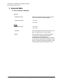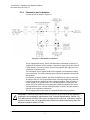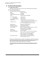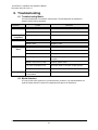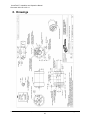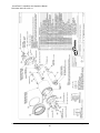
1
VersaFinish™ Axially Compliant Robotic Finishing Tool (Model 9150-ACT-390) Installation and Operation Manual 9150-ACT-390 Document # 9610-50-1012-14 December 2012 Engineered Products for Robotic Productivity Pinnacle Park 1031 Goodworth Drive Apex, NC 27539 Tel: 919.772.0115 Fax: 919.772.8259 www.ati-ia.com Email: [email protected] VersaFinish™ Installation and Operation Manual Document: 9610-50-1012-14 ! CAUTION: This manual describes the function, application and safety considerations of this product. This manual must be read and understood before any attempt is made to install or operate this product, otherwise damage to this product or unsafe conditions may occur. Information contained in this document is the property of ATI Industrial Automation, Inc. (ATI) and shall not be reproduced in whole or in part without prior written approval of ATI. The information herein is subject to change without notice. This manual is periodically revised to reflect and incorporate changes made to the product. The information contained herein is confidential and reserved exclusively for the customers and authorized agents of ATI Industrial Automation and may not be divulged to any third party without prior written consent from ATI. No warranty including implied warranties is made with regard to accuracy of this document or fitness of this device for a particular application. ATI Industrial Automation shall not be liable for any errors contained in this document or for any incidental or consequential damages caused thereby. ATI Industrial Automation also reserves the right to make changes to this manual at any time without prior notice. ATI assumes no responsibility for any errors or omissions in this document. Users’ critical evaluation of this document is welcomed. Copyright by ATI Industrial Automation. All rights reserved. How to Reach Us Sales, Service and Information about ATI products: ATI Industrial Automation 1031 Goodworth Drive Apex, NC 27539 USA www.ati-ia.com Tel: 919.772.0115 Fax: 919.772.8259 E-mail: [email protected] Technical support and questions: Application Engineering Tel: 919.772.0115, Option 2, Option 2 Fax: 919.772.8259 E-mail: [email protected] Pinnacle Park 1031 Goodworth Drive Apex, NC 27539 Tel: 919.772.0115 Fax: 919.772.8259 www.ati-ia.com Email: [email protected] 2 VersaFinish™ Installation and Operation Manual Document: 9610-50-1012-14 Glossary of Terms Term Definition Adapter Device for attaching the tool to robots or work surfaces. Air Filter Device for removing contamination from air supply lines. Typically refers to removal of particulates. Air Lubricator Device for adding controlled volumes of lubricating oil to the air supplying the air motor. Vane Motor Air motor that drives the tool spindle. Bur Any unwanted, raised protrusion on the workpiece. Chuck Gripping device used to hold tools and media to the spindle. Compliance The ability of the spindle to passively move in response to protrusions on or deviations of the work piece. Regulator Device used to set and control the supplied air pressure to lower acceptable levels. Solenoid Valve Electrically controlled device for switching air supplies on and off. Spindle The rotating portion of the tool assembly. Gearhead A gearbox responsible for reducing the spindle speed of the air motor. Main Housing The main cylindrical body of the unit which includes the mounting features. Media Term referring to tools and/or abrasives held by the tool during the completion of a manufacturing process. Rear Housing Rear cover to the main housing. This body includes a connection port for the compliance air supply and feed-through seals for optional electrical sensors. Forward Sensor The forward sensor is an inductive proximity switch which is ON when the spindle is in the fully forward position indicating there is no contact with the tool. Retract Sensor The retract sensor is an optional inductive proximity switch which is ON when the spindle is in the fully back position indicating there is no further motion possible. Tachometer Sensor The tachometer sensor is an optional inductive proximity switch which monitors the rotation of a disk mounted behind the chuck on the spindle. The sensor will deliver two OFF pulses per spindle rotation. It is recommended that the tachometer sensor be utilized for process development but removed from the unit when in a production environment. Pinnacle Park 1031 Goodworth Drive Apex, NC 27539 Tel: 919.772.0115 Fax: 919.772.8259 www.ati-ia.com Email: [email protected] 3 VersaFinish™ Installation and Operation Manual Document: 9610-50-1012-14 Table of Contents 1. General Data ................................................................................................................ 5 1.1 2. Handling, Installation, Storage and Transportation .................................................. 6 2.1 2.2 2.3 2.4 2.5 3. 5.6 5.7 Routine Operational Maintenance ................................................................................ 16 Media Replacement ..................................................................................................... 16 Boot Replacement ........................................................................................................ 16 Air Motor Replacement................................................................................................. 17 Sensor Replacement .................................................................................................... 18 5.5.1 Forward Sensor (Option -F) ............................................................................ 18 5.5.2 Retract Sensor (Option -R) ............................................................................. 19 5.5.3 Tachometer Sensor (Option -T) ...................................................................... 19 Pneumatics ................................................................................................................... 20 Lubrication .................................................................................................................... 20 Troubleshooting ........................................................................................................ 21 6.1 6.2 7. 8. 9. 10. General Precautions ..................................................................................................... 12 VersaFinish Working Environment ............................................................................... 13 Sensor Connections ..................................................................................................... 13 Media Considerations ................................................................................................... 14 Tool Position and Programming ................................................................................... 14 Spindle Operation and Media Selection ....................................................................... 15 Safety Precautions ....................................................................................................... 15 Maintenance Instructions.......................................................................................... 16 5.1 5.2 5.3 5.4 5.5 6. Product Description ........................................................................................................ 9 Technical Specifications ................................................................................................. 9 Operation ................................................................................................................... 12 4.1 4.2 4.3 4.4 4.5 4.6 4.7 5. Inspection of Condition When Delivered ........................................................................ 6 Unpacking and Handling ................................................................................................ 6 Installation ...................................................................................................................... 6 2.3.1 Mounting Adapter and Air Supply ..................................................................... 6 2.3.2 Pneumatics and Lubrication ............................................................................. 7 Transportation and Protection during Transportation .................................................... 8 Storage and Preventive Maintenance during Storage ................................................... 8 Technical Description ................................................................................................. 9 3.1 3.2 4. Environmental Limitations .............................................................................................. 5 Troubleshooting Matrix ................................................................................................. 21 Media Selection ............................................................................................................ 21 Recommended Spare Parts ...................................................................................... 22 Drawings .................................................................................................................... 23 Terms and Conditions ............................................................................................... 26 Attachments ............................................................................................................... 27 Pinnacle Park 1031 Goodworth Drive Apex, NC 27539 Tel: 919.772.0115 Fax: 919.772.8259 www.ati-ia.com Email: [email protected] 4 VersaFinish™ Installation and Operation Manual Document: 9610-50-1012-14 1. General Data 1.1 Environmental Limitations Operation Installation position Mounted to machining center by means various, customer-supplied tool holders/adapters. Temperature range 5°C–35°C 41F–95F Storage Temperature range 0°C–45°C 32F–113F Conditions The tool should be stored in its crate and in a dry place. Consult Section 2.5 of this manual. Utilities The tool requires clean, dry, filtered, lubricated air. The use of a coalescing filter and filter elements rated 5 micron or better is recommended. The 390 Watt air motor consumes air at a rate of 9 liters/second (19 CFM) at 6.2 bar (90 psi). A separate air pressure regulator is used to pneumatically control the compliance force. Pinnacle Park 1031 Goodworth Drive Apex, NC 27539 Tel: 919.772.0115 Fax: 919.772.8259 www.ati-ia.com Email: [email protected] 5 VersaFinish™ Installation and Operation Manual Document: 9610-50-1012-14 2. Handling, Installation, Storage and Transportation 2.1 Inspection of Condition When Delivered Upon receipt, the following should be checked: - Delivery in accordance with freight documents - Damage to packaging. If there is damage to any of the packaging or if any of the goods have been exposed to abnormal handling, unpack those parts that may have been damaged for a closer inspection. If necessary, notify ATI for assistance in evaluation of the product condition. 2.2 Unpacking and Handling The VersaFinish axially compliant tool should always be placed inside the accompanying box (crate) during transportation, storing, and handling. 2.3 Installation 2.3.1 Mounting Adapter and Air Supply The tool is designed for side mounting. ATI offers a side interface plate kit for bench mounting. The tool must be rigidly mounted prior to use. Under no circumstances should the unit be used for manual/hand operations. Once securely mounted, the unit should be supplied with clean, lubricated air filtered five (5) micron or better. The use of a coalescing filter is recommended to remove trace moisture from the air supply. Air line fittings supplying the VersaFinish should be installed with care using a minimum of tape or liquid sealant. To prevent contaminant damage to the air motor, all air lines should be blown down to remove debris prior to connection of the VersaFinish. ! CAUTION: The VersaFinish must be supplied with clean, lubricated air filtered five micron or better. The use of a coalescing filter is recommended. Water damage of the air motor or damage associated with debris in the air lines is not covered under warranty. Pinnacle Park 1031 Goodworth Drive Apex, NC 27539 Tel: 919.772.0115 Fax: 919.772.8259 www.ati-ia.com Email: [email protected] 6 VersaFinish™ Installation and Operation Manual Document: 9610-50-1012-14 2.3.2 Pneumatics and Lubrication Connect the tool as shown in Figure 2.3 Figure 2.3—Pneumatic Connections The air supply should be dry, filtered, and lubricated as described in Section 5.6. A high-flow air pressure control regulator is required to supply the spindle motor at 6.2 bar (90 psi). A second, precision, self-relieving regulator will supply air for the compliance or centering force. The compliance force is applied axially and is adjusted until the desired finishing result is achieved. The robot traversing speed will also be adjusted to achieve the desired finish. Conventional, customer-supplied, pneumatic components are used to control the air supply to the tool. ATI recommends that the user install a high-flow pneumatic pressure regulator and a high-flow valve to properly supply a stable air supply of 6.2 bar (90 psi) to the spindle motor. (ATI Part # 9150-FRL-3 or equivalent, see Section 3.2 for the maximum flow requirements.) While the spindle motor can be operated below 6.2 bar, it will not develop full power or speed. Very little airflow is required for the compliance mechanism. The air supply solenoid valve must be controlled through robot or controller. ! CAUTION: Pneumatic components used for the motor drive circuit must be capable of meeting the air consumption requirements (See Technical Specifications, Section 3.2). Poor performance will result if the correct components are not used. Lubricators must be located as close to the unit as possible with performance rapidly deteriorating when the distance exceeds 5 meters (15 feet). Pinnacle Park 1031 Goodworth Drive Apex, NC 27539 Tel: 919.772.0115 Fax: 919.772.8259 www.ati-ia.com Email: [email protected] 7 VersaFinish™ Installation and Operation Manual Document: 9610-50-1012-14 Function Connection Type Pressure 1/4-NPT Port 6.2 bar (90 psi) Compliance (Axial) Force 1/8-NPT Port .34–4.1 bar (Maximum) (5–60 psi) Exhaust 1/4-NPT Port (High-flow Muffler Supplied) Not Applicable Motor Inlet Table 2.1—Pneumatic Connections The tool must be plumbed using flexible tubing. The inside diameter of the tubing should be as large as practical to minimize pressure drop to the spindle motor [3/8" (10mm) minimum]. The air motor is quiet and vents air to the environment through the supplied highflow muffler at the rear of the unit. The customer may choose to replace the muffler with tubing to carry exhaust away from the work area. Such tubing must be as large and flexible as possible to minimize pressure drops and allow unrestricted axial motion respectively. To reduce the sound level in neighboring working areas, a customer-supplied barrier surrounding the installation may be installed (Plexiglas or Lexan is preferred, see Section 3.2). The compliance force air supply pressure regulator should be adjusted between 0.34–4.1 bar (5–60 psi). When testing for the proper contact force, start with a very low pressure and increase slowly until the desired process result is achieved. 2.4 Transportation and Protection during Transportation The VersaFinish is packaged in a crate designed to secure and protect it during transportation. Always use the crate when transporting the VersaFinish in order to minimize the risk of damage. 2.5 Storage and Preventive Maintenance during Storage For short-term storage, the tool should be stored in a dry place in its crate when it is not in use. For long-term storage, the VersaFinish should be thoroughly cleaned of any burrs, dust, or debris. To protect the air motor, the user may wish to inject several drops of oil directly into the motor input followed by a short burst of supply air to insure the vanes and internal components are completely lubricated. The units should not be disassembled. Place the tool inside a sealed, plastic bag and place the bagged tool inside the crate. Pinnacle Park 1031 Goodworth Drive Apex, NC 27539 Tel: 919.772.0115 Fax: 919.772.8259 www.ati-ia.com Email: [email protected] 8 VersaFinish™ Installation and Operation Manual Document: 9610-50-1012-14 3. Technical Description 3.1 Product Description Attached at the end of this document you will find the VersaFinish product description. 3.2 Technical Specifications Main specifications for the axially compliant tool: Motor Air motor, vane type Idle Speed 5,600 RPM Working Speed (max. power) 2,600 RPM Power 390 W (0.52 hp) at 2,600 RPM Torque (max. power) 1.4 Nm (1 lb-ft) (starting/stall) 2.7 Nm (2 lb-ft) Weight total (w/o adapter) 3.3 kg (7.25 lbs) Compensation 15 mm max. axial, 7–8 mm recommended (0.59 in. max. axial, 0.28–0.32 in. recommended) Compliance force 14–74 N, @ supply pressure of 0.34–4.1 bar (3.2–16.7 lbs, @ supply pressure of 5–60 psi) Surface speed Dependent on media geometry Spindle Air pressure 6.2 bar (90 psi) maximum Air consumption (max.) approximately 9 l/s (19 CFM) 3 Oil consumption Approx. 3–4 drops of oil per minute (1 drop = 15mm ) by oil fog at max. air consumption Chuck size 3/8" Standard (Specials Available) Abrasive media Customer-supplied Special tools (supplied) Open end spanner, 15mm (Chuck & Collet Models) Jacobs chuck key, KG1 (Key Chuck Models) Open end spanner, 3/4‖ (Collet Models) Open end spanner, 9/16‖ (Collet Models) Sound Pressure Level Less than 75 dBA , No-Load at a Distance of 5 feet (1.5 meters) From Tool Because the working environment is unknown, it is impossible to predict the noise that will occur during an operation. The tool may also excite resonant frequencies on equipment to which it is mounted creating higher sound pressure levels than the unit by itself. Each VersaFinish is tested for proper operation prior to shipment. The following charts show measured forces relative to applied compliance air pressure. Measurements may vary from one product to another, and should only be treated as nominal. Pinnacle Park 1031 Goodworth Drive Apex, NC 27539 Tel: 919.772.0115 Fax: 919.772.8259 www.ati-ia.com Email: [email protected] 9 VersaFinish™ Installation and Operation Manual Document: 9610-50-1012-14 ACT-390 Horizontal Compliance Force 30 140 25 120 Compliance Forec (N) Compliance Forec (lbf) ACT-390 Horizontal Compliance Force 20 15 10 5 100 80 60 40 20 0 0 0 20 40 60 80 0 100 1 2 3 4 5 6 7 Air Pressure (bar) Air Pressure (psi) Figure 3.1—ACT-390 Horizontal Compliance Force Curves The force characteristics shown graphically above are for horizontal, rigidly-mounted installations. The weight of the motor, chuck, and abrasive media must be added to this if the motor is mounted vertically with the spindle down or subtracted with the spindle pointed up. Units mounted at angles between horizontal and vertical provide a compliance force that must be calculated based on the specific mounting geometry or orientation. The air motor operating speed will change according to load applied to it developing the power required for the specific task being attempted. The idle speed of the motor will be its maximum as no load is applied. This will drop to a lower operating speed where it will develop the maximum torque. If the torque required exceeds the maximum available, the motor will stall. ACT-390 Motor Torque Performance (lb-ft) ACT-390 Motor Torque Performance (N-m) 3.0 Torque (Nm) Torque (lb-ft) 2.0 1.0 0.0 2.0 1.0 0.0 0 2000 4000 6000 0 RPM 2000 4000 6000 RPM Figure 3.2—ACT-390 Motor Torque Curves Pinnacle Park 1031 Goodworth Drive Apex, NC 27539 Tel: 919.772.0115 Fax: 919.772.8259 www.ati-ia.com Email: [email protected] 10 VersaFinish™ Installation and Operation Manual Document: 9610-50-1012-14 ACT-390 Motor Power (hp) ACT-390 Motor Power (kW) 0.6 0.4 0.5 Power (kW) Power (hp) 0.3 0.4 0.3 0.2 0.2 0.1 0.1 0.0 0.0 0 2000 4000 6000 0 RPM 2000 4000 6000 RPM Figure 3.3—ACT-390 Motor Power Curves Pinnacle Park 1031 Goodworth Drive Apex, NC 27539 Tel: 919.772.0115 Fax: 919.772.8259 www.ati-ia.com Email: [email protected] 11 VersaFinish™ Installation and Operation Manual Document: 9610-50-1012-14 4. Operation These operating instructions are intended to help system integrators program, start up, and complete an installation containing an axially compliant tool. The system integrator should be familiar with the task in general and should have extensive knowledge of programming and automation. Important Note Regarding Operation: The air motor is supported by two guide rods attached to the front plate of the deburring tool. To prevent binding of the compliance, one of these guide rods is rigidly attached to the front plate. The second guide rod and the compliance piston rods are free to float in the front plate. This allows the motor assembly to achieve free compliant motion while resisting the motor’s torque. DO NOT attempt to change the floating nature of the rods by adding washers or additional thread locker. These actions will prevent the rods from floating, which will result in binding of the tool’s compliance. ! CAUTION: The floating VersaFinish rods attached to the front plate must not be restrained. Rigid mounting of the rods attached to the front plate will result in binding of the tool’s axial compliance. 4.1 General Precautions It is important that all personnel involved in operation of the tool have a thorough understanding of the operating procedures. Failure to follow these or neglecting safety precautions can create hazardous situations, which may, in the worst case, injure personnel or damage the installation and the tool. The VersaFinish must only be used for automated applications. DANGER: Never use the VersaFinish for purposes other than automated processes. Never use the VersaFinish as a hand-held machine. While the VersaFinish provides axial travel, it is not designed to eliminate tool chatter which will be experienced in full contact operations, such as countersinking. Rigid tools, such as milling machines, are required for such applications. It may be dangerous to operate the VersaFinish for these purposes. If a failure occurs due to forces caused by improper use, hazardous situations for both personnel and equipment could be created. The VersaFinish is not designed to support radial loads. The use of radial media (wheel brushes and sanding drums) in the unit is discouraged as this will lead to binding in the linear slides preventing axial motion. Reduce the feed rate when the work piece and the tool are making initial contact. Making the contact movement between the tool and the work piece too fast may in some situations result in a collision. Collisions may create hazardous situations for both personnel and equipment. When performing maintenance, always remember to tighten all the fasteners. When replacing media always secure it correctly and insure that the chuck is tightened. See Section 5.1. The VersaFinish air motor is equipped with an integral speed reduction gearbox. The life of this gearbox will be reduced if the media extends a long distance from the tip of the spindle. Whenever possible, select media and mounting adapters for media that are short and position the work as close to the VersaFinish as possible. Pinnacle Park 1031 Goodworth Drive Apex, NC 27539 Tel: 919.772.0115 Fax: 919.772.8259 www.ati-ia.com Email: [email protected] 12 VersaFinish™ Installation and Operation Manual Document: 9610-50-1012-14 DANGER: Never use the VersaFinish in a manner to produce radial loads. Avoid using the VersaFinish for countersinking or drilling. 4.2 VersaFinish Working Environment As described in previous sections, the VersaFinish should only be used in an automated cell/chamber. The work cell must be secured by means of barriers to prohibit personnel from entering the cell. A lockable door should be included as a part of the barrier in order to facilitate access to the cell for authorized personnel only. The barrier could consist partly or fully of Plexiglas to facilitate observation of the manufacturing process. During system or tool maintenance, make sure the VersaFinish and equipment are stopped before entering the cell. Never be present in the cell when the tool is running when installing and testing. Be aware of rotating parts. Use eye-protection while working around the tool. Be aware of high sound levels. While the VersaFinish air motor is not loud, the cutting action associated with many processes frequently is. Always use hearing protection while working in the neighborhood of the production cell. 4.3 Sensor Connections The VersaFinish tool can be equipped with up to three sensors to monitor spindle position and speed. These include the Forward, Retract, and Tachometer sensors. Each sensor is a PNP (sourcing) type proximity switch using three wire electrical hook-up. The Forward and Tachometer sensors are a standard 8mm threaded body 3-pin type. Unterminated cables are connected to these sensors and exit the rear of the deburring tool. The Retract sensor is a flat proximity switch whose short cable is terminated with a male threaded 8mm connector. This connection may be extended using any industrystandard 8mm 3-pin cable. ATI part numbers for two such cables will be found on the customer drawings for the VersaFinish located in Section 8.1 of this manual. The electrical connections for 3-pin proximity sensors are color-coded and adhere to industry-standards. The blue sensor wires are connected to 0V and the brown wires are connected to a positive voltage source between 10V and 30VDC. With the PNP sensors used on VersaFinish, the black wire is the output signal, which will go ―high‖ when the switch closes (turns on). Thus, the sensor ―sources‖ power to the load or monitoring circuit. Typical PNP Proximity Switch Schematic Typical Male PNP Connector Pin Out (Face View of Male 8mm Connector) See Section 5 of this manual for more information on setting and using these sensors. Pinnacle Park 1031 Goodworth Drive Apex, NC 27539 Tel: 919.772.0115 Fax: 919.772.8259 www.ati-ia.com Email: [email protected] 13 VersaFinish™ Installation and Operation Manual Document: 9610-50-1012-14 4.4 Media Considerations For instructions on how to replace the media, see Section 5.1. In most applications, no cooling or lubrication of the part or tool is necessary nor is it desirable. For some materials and situations, the addition of coolants or compressed air may aid the cutting process. Any application of coolant must be exercised with care to prevent fluids from entering the tool or its chuck. As mentioned in Section 4.1, select media and media holders that position the work piece as close to the VersaFinish as possible. 4.5 Tool Position and Programming The VersaFinish dimensions are provided in the drawings in Section 7. The VersaFinish provides axial compliance and performs best when spindle is displaced through approximately one-half of its allowable travel (approximately 8mm). The tool spindle must never be running while programming a machining center. During teaching, the compliance air must be on and supplied near 1.4 bar (20psi). A simple programming method is to replace the desired media with a dowel pin which projects 8mm less from the tool's chuck than the production media that will be used. The tip of this dowel can then be used to contact the part when teaching the robot path (see Figure 4.1). Figure 4.1—VersaFinish Dowel Teaching Tool The short, teach dowel pin with the tool spindle fully extended (left in Figure 4.1) will simulate the position of the spindle deflected 8mm when the actual media/tool is installed (right in Figure 4.1). When running the program the first time, observe the path with the compliance air supply turned down to approximately 1.4 bar (20 psi). Verify that at operational speed the media is deflected but contacts the work surface. Once the path has been confirmed, the compliance force of the media should be adjusted as described in Section 2.3.2 in order to achieve the desired finish. Pinnacle Park 1031 Goodworth Drive Apex, NC 27539 Tel: 919.772.0115 Fax: 919.772.8259 www.ati-ia.com Email: [email protected] 14 VersaFinish™ Installation and Operation Manual Document: 9610-50-1012-14 4.6 Spindle Operation and Media Selection When used with flexible abrasive media, the VersaFinish will perform best when the rotating media approaches the burr in a direction that will fold the burr back on itself. This will allow the media to remove material rapidly without excessive force and without the creation of a secondary bur. This will decrease the cycle time for the operation while extending the life of the tool and the consumable media. The VersaFinish spindle rotates clockwise when viewed from behind. The selection of such media is highly dependent upon the work piece material and geometry, and the amount of material to be removed. It is not practical to present all the possibilities in this document. 4.7 Safety Precautions Never use or start the VersaFinish without first reading and understanding the operating procedures described in this manual. Make sure that the VersaFinish is mounted as described in this manual. Never use the VersaFinish for any purposes or in any ways not explicitly described in this manual. Make sure that the pneumatic control equipment is connected as described. Only original spare parts supplied by ATI must be used. Install a barrier to prohibit people from approaching the VersaFinish while in operation. Never be present near the VersaFinish while it is started or running. If it is necessary to approach the VersaFinish while in motion, stand behind appropriate Plexiglas windows. Be aware of rotating parts. Abrasive media must be rated for at least 5,600 RPM Use eye protection. Be aware of high sound levels during cutting. Always use hearing protection while working in the neighborhood of the VersaFinish. Pinnacle Park 1031 Goodworth Drive Apex, NC 27539 Tel: 919.772.0115 Fax: 919.772.8259 www.ati-ia.com Email: [email protected] 15 VersaFinish™ Installation and Operation Manual Document: 9610-50-1012-14 5. Maintenance Instructions Important Note Regarding Operation: The air motor is supported by two guide rods attached to the front plate of the deburring tool. To prevent binding of the compliance, one of these guide rods is rigidly attached to the front plate. The second guide rod and the compliance piston rods are free to float in the front plate. This allows the motor assembly to achieve free compliant motion while resisting the motor’s torque. DO NOT attempt to change the floating nature of the rods by adding washers or additional thread locker. These actions will prevent the rods from floating, which will result in binding of the tool’s compliance. ! CAUTION: The floating VersaFinish rods attached to the front plate must not be restrained. Rigid mounting of the rods attached to the front plate will result in binding of the tool’s axial compliance. 5.1 Routine Operational Maintenance The VersaFinish is warranted by ATI for a period of one year or 2000 hours of operation from date of purchase, whichever occurs first. The tool utilizes a vane-type air motor with integral speed reduction gearbox. When subjected to normal use, this robust unit will provide many hours of operation before service or repair is necessary. When subjected to high shock loading or periods of continuous service without interruption, the unit will require service or repair earlier. While simple in design, there are few user-serviceable parts in the assembly. The user is encouraged to return the unit to ATI for service. The following information is provided to assist the user when they choose to service the unit in the field. For all service, it is recommended that the air supply (before the solenoid valves) be disconnected. Drain any trapped air pressure in the lines. It is suggested that the air supply be ―locked out‖ to prevent accidental operation of the spindle. During maintenance operations, refer to drawings in Section 7. 5.2 Media Replacement The standard VersaFinish unit ships with a simple drill chuck to hold customer-supplied media. A standard chuck key is used to loosen and tighten the chuck. When tightening the chuck, insert and turn the key into each of the three holes around the chuck's perimeter. ATI can design special media holders for custom applications upon request. It is assumed that the customer requesting such special media holding devices will be familiar with their use. When in doubt, the customer should refer to the manufacturer of the media to determine how to properly secure that media to the spindle. 5.3 Boot Replacement The tool is equipped with a simple boot between the moving motor mounting plate and the main housing. This boot is provided to minimize contamination of the guide and piston rods allowing free axial motion. This boot is not provided as a safety device. Under no circumstances should the user operate the unit without the boot. The user should never have their hands on or near the unit when in operation. To replace the boot, perform the following steps. 1. Discharge any pressure in the air lines to the tool's spindle and compliance connections. 2. Use a suitable pick or small ball-end hex wrench to lift and remove the o-ring securing the boot to the front plate of the unit. 3. Similarly remove the o-ring securing the boot to the main housing. Pinnacle Park 1031 Goodworth Drive Apex, NC 27539 Tel: 919.772.0115 Fax: 919.772.8259 www.ati-ia.com Email: [email protected] 16 VersaFinish™ Installation and Operation Manual Document: 9610-50-1012-14 4. Use the pick to lift the boot as necessary and slide it forward off the spindle end of the tool. 5. To refit the boot perform the following steps: Slip the first o-ring up and over the boss of the main housing, temporarily leaving the o-ring on the main housing. Slip the boot over the moving motor mount plate and onto the main housing. Position the boot so its locking surfaces engage the grooved boss on both the moving plate and the main housing. Refit both o-rings to secure the boot. 5.4 Air Motor Replacement The air motor must be operated using lubricated air or it will fail and require replacement. The motor includes a gearbox (gearhead) to lower the spindle speed. Maintenance of either the motor or the gearbox requires the motor be removed from the tool. VersaFinish units with defective motors should be returned to ATI during the warranty period. Should the customer wish to replace the motor after the warranty period, the following steps must be performed. 1. Discharge any pressure in the air lines to the tool's spindle and compliance connections. 2. Disconnect the flexible tubing supplying the air motor and compliance. 3. Disconnect any air lines connected to the motor's exhaust port in place of the muffler. 4. Thread ¼‖ NPT straight fittings or pipe nipples into the motor's supply and exhaust ports to use as handles during the removal sequence. 5. Use the 15 mm open-end wrench to hold the spindle nut behind the chuck. 6. Insert the chuck key into the chuck. While holding the 15 mm wrench securely, unscrew the chuck counterclockwise using the chuck key as a lever. 7. With the chuck removed, hold the spindle threads with fingers and remove the 15 mm nut previously held by the open end wrench. 8. Use a hex wrench to loosen the four flat-head screws securing the seal plate to the moving motor mount plate at the front of the tool, thus freeing the air motor. 9. At the rear of the unit, grasp the fittings/nipples installed previously in the rear of the air motor and use them to rotate the motor CLOCKWISE from the rear. This will unscrew the motor from the front plate of the tool. (NOTE: The motor mount uses left-hand threads, rotate CLOCKWISE to remove). 10. Reassembly is the reversal of these steps noting the following important steps. Fit the seal plate to the moving motor mount plate tightening the flat-head screws until they bottom out. Back the flat-head screws out one-half (1/2) turn. Thread the motor into the front plate (remembering that the motor mount has lefthand threads and must be turned counterclockwise from the rear to tighten). When the motor bottoms out against the seal plate, return to the flat-head screws on the seal plate and tighten them securely. Apply a thin film of grease to the shoulder of the 15 mm nut that goes behind the chuck and thread it onto the motor shaft until it bottoms out. Thread the chuck onto the spindle until it bottoms out on the 15 mm nut. As during removal, insert the chuck key into the chuck and use it as a lever to tighten the chuck against the 15 mm nut held by the open end wrench. Reinstall the desired air supply fittings as appropriate. Pinnacle Park 1031 Goodworth Drive Apex, NC 27539 Tel: 919.772.0115 Fax: 919.772.8259 www.ati-ia.com Email: [email protected] 17 VersaFinish™ Installation and Operation Manual Document: 9610-50-1012-14 5.5 Sensor Replacement The VersaFinish may be outfitted with up to three (3) proximity sensors. These sensors may be monitored by the customer to determine the following information. 1. Option –F: The Forward Sensor. This sensor is included on all units. It is ON when the spindle is fully forward. 2. Option –R: The Retract Sensor. This sensor is ON when the spindle is fully Retracted. 3. Option –T: The Tachometer. This sensor delivers two (2) OFF pulses for every spindle rotation. The -R and -T are optional features specified at the time of order placement. These options can be added in the field by following the reassembly and adjustment steps below. 5.5.1 Forward Sensor (Option -F) The forward sensor is mounted inside the VersaFinish housing. When the spindle is fully forward the sensor will turn on. The spindle must be displaced approximately 1mm to the rear before the sensor will turn off. This may be utilized to insure that the media is in contact with the part to be deburred. To remove, install, and adjust the sensor perform the following steps. 1. Discharge any pressure in the air lines to the tool's spindle and compliance connections. 2. Remove the three socket head screws holding the rear housing to the front housing. 3. Remove the rear housing and observe the nickel plated cylindrical sensor mounted in the plastic block. 4. Remove the screw securing the plastic block to the housing and remove the sensor, pulling its lead through the rubber seal of the rear housing. 5. Reassembly is the reversal of these steps noting the following important steps. Fit the plastic block to the housing and push the spindle fully forward. Adjust the clearance between the face of the nickel plated sensor and the head of the socket head screw until the radial gap is approximately 1 mm. Tighten the screw securing the block to the housing. Pass the sensor wire out of the rear housing seal and refit the rear housing to the main housing of the tool. Insure that all o-ring seals are in place before securing the screws. Connect the sensor wires to an appropriate power supply. (24V DC with blue = 0V, brown = +24V, and black = output). Remove the stainless button head screw from the rear housing and reach through the opening with the appropriate sized hex wrench to turn the adjusting screw. Push the motor mounting plate all the way forward. With the spindle pushed all the way forward, turn the target socket head screw counter clockwise until the sensor just turns OFF. Turn the target screw one complete turn clockwise. Refit the stainless steel button head screw. Pinnacle Park 1031 Goodworth Drive Apex, NC 27539 Tel: 919.772.0115 Fax: 919.772.8259 www.ati-ia.com Email: [email protected] 18 VersaFinish™ Installation and Operation Manual Document: 9610-50-1012-14 5.5.2 Retract Sensor (Option -R) The retract sensor is mounted to the rear housing inside the tool. When the spindle is within approximately 1.5mm of being fully retracted the sensor will turn on. This may be utilized to indicate when excessive brush force is being applied (i.e., the brush has been pushed back so far and so hard that the end of compliance travel has been reached). To remove, and install the sensor perform the following steps (there is no adjustment). 1. Discharge any pressure in the air lines to the tool's spindle and compliance connections 2. Remove the three socket head screws holding the rear housing to the front housing. 3. Locate the flat sensor secured to the rear housing using a single flat-head screw. 4. Remove the flat-head screw and pass the sensor and wire through the slot and rubber seal on the rear housing. 5. Reassembly is the reversal of these steps. 5.5.3 Tachometer Sensor (Option -T) The tachometer sensor is an optional speed sensing system that allows the user to monitor the rotating speed of the spindle. A target disk is sandwiched between the spindle chuck and the nut securing it. Two equally spaced holes in this plate serve as targets for the sensor. The sensor is mounted on the moving motor mount plate. For every rotation of the spindle there will be two OFF pulses to be monitored by the customer's tachometer circuit. NOTE: The tachometer option is for process development. The thin target disk may be damaged in a production environment. Once process development is complete, the customer is advised to remove the target disk from the spindle or to insure that nothing can accidentally strike the target. To remove, install, and adjust the tachometer sensor, perform the following steps. 1. Discharge any pressure in the air lines to the tool's spindle and compliance connections. 2. Follow the instructions to remove the spindle chuck as described under Section 5.4—Air Motor Replacement. 3. Remove the boot as described under Section 5.3—Boot Replacement. 4. Remove the rear housing as described previously in the Forward and Retract Sensor sections. 5. At the front of the tool, loosen the jam nut securing the tachometer sensor to the moving motor mount plate. 6. Using the sensor's cable as a tool, rotate the cable counterclockwise to unscrew the sensor and withdraw it to the rear of the tool. 7. Reassembly is the reversal of the steps above observing the following points: Fit the cable to the sensor, insert it through the main housing and, using fingers (and the attached cable), thread it through the moving motor mount plate. Fit the sensor jam nut and a single lock washer finger tight to the front of the moving motor plate. Fit the large target plate to the motor spindle and fit the chuck. Tighten the chuck as described in Section 5.4—Air Motor Replacement. Pinnacle Park 1031 Goodworth Drive Apex, NC 27539 Tel: 919.772.0115 Fax: 919.772.8259 www.ati-ia.com Email: [email protected] 19 VersaFinish™ Installation and Operation Manual Document: 9610-50-1012-14 Using fingers, advance the tachometer sensor until there is a gap of 1mm between the sensor and the back of the target plate. Rotate the spindle through one complete revolution by turning the chuck. Observe the sensor to target gap and adjust the sensor position as necessary so the sensor does not hit the target nor has a gap greater than 1mm. The target will have some warpage causing axial runout. This is normal and acceptable. Tighten the sensor jam nut. DO NOT USE EXCESSIVE TORQUE ON THIS NUT. Tighten the nut finger-tight followed by an additional 1/12 turn with a wrench. 5.6 Pneumatics The air tubing/lines to the VersaFinish should routinely be checked for their general condition and replaced as required. The lines must be highly flexible to allow free axial motion of the tool. The air to the tool must be filtered, dry, and lubricated. The air filters should be checked and replaced as required to maintain optimum performance. Check the oil level in the lubricator daily, adding oil as necessary. The life of the filter elements is dependent on the quality of compressed air at the customer’s facility and therefore cannot be estimated. 5.7 Lubrication The VersaFinish air motor must be supplied with clean, dry, filtered, lubricated air. The air supply should be dry, filtered, and lubricated. A coalescing filter with elements rated for 5 micron or better is recommended. Air tool oil must be applied at a rate of 0.05 ml per 1000 liters of air [0.002 fluid ounces (U.S.) per 36 cubic feet]. When an oil-fog type lubricator is utilized, this will equate to approximately 3–4 drops per minute at the rated air consumption of 8.3 liters/second (17.6 CFM). It is imperative that the lubricator be located within 15 feet of the tool. ! CAUTION: Failure to lubricate the air to the vane motor will result in premature failure of the motor and is not covered under warranty. It is recommended that the customer use a coalescing filter and filter elements rated 5 micron or better to remove trace moisture. A lubricator should be located within 15 feet of the tool. Pinnacle Park 1031 Goodworth Drive Apex, NC 27539 Tel: 919.772.0115 Fax: 919.772.8259 www.ati-ia.com Email: [email protected] 20 VersaFinish™ Installation and Operation Manual Document: 9610-50-1012-14 6. Troubleshooting 6.1 Troubleshooting Matrix Process development is an iterative, learning task. The following table is presented to assist in solving various problems. Cause Problem Wear Solution Too heavy a cut Decrease width of cut/make multiple passes Feed rate is too slow Increase feed rate Unequal compliance Defective regulator Replace regulator Poor finish Feed rate is too fast Reduce feed rate Media is worn Replace media Incorrect feed rate Reduce feed rate Too heavy a cut Decrease width of cut/make multiple passes Incorrect feed direction Change path Not enough or no drive air Check drive air regulator for 90 psi (6.2 bar) and for leaks Media is not secure in collet Properly tighten chuck Too much compliance force Decrease width of cut/make multiple passes Compliance exceeded Examine/correct path Guide rods and pistons contaminated Remove boot, clean and lubricate rods. Secondary Burrs Spindle stalls Sticking spindle 6.2 Media Selection ATI can provide some guidance is in media selection, however, only experimentation will yield the results desired. Contact ATI's Applications Engineers for assistance. Pinnacle Park 1031 Goodworth Drive Apex, NC 27539 Tel: 919.772.0115 Fax: 919.772.8259 www.ati-ia.com Email: [email protected] 21 VersaFinish™ Installation and Operation Manual Document: 9610-50-1012-14 7. Recommended Spare Parts For repair and spare parts please contact ATI. For an exploded drawing showing all the components of the VersaFinish, see Section 7—Drawings. Suggested user replaceable, optional, and spare parts are listed in the tables below. All other repairs must be performed by ATI. The following optional parts are available for the VersaFinish: Part Number Description 9150-FRL-3 Precision Air Filter/Regulator/Lubricator (Spindle Air, 90 psi) 9150-P16-B-G Precision Air Pressure Regulator (Compliance Air, 60 psi) 9150-ACT-T-3169A26 VersaFinish Chuck Key, KG1 (for Keyed Chuck Models) 9150-ACT-T-841015mm 15mm Open End Spanner (all Models) 9150-ACT-T-841075in 3/4‖ Open End Spanner (for DA200 Collet Models) 9150-ACT-T-841056in 9/16‖ Open End Spanner (for DA200 Collet Models) 9150-ACT-C-84911163 1/4‖ DA200 Collet (for DA200 Collet Models) 9150-ACT-C-CBC200 Collet Nut (for DA200 Collet Models) Pinnacle Park 1031 Goodworth Drive Apex, NC 27539 Tel: 919.772.0115 Fax: 919.772.8259 www.ati-ia.com Email: [email protected] 22 VersaFinish™ Installation and Operation Manual Document: 9610-50-1012-14 8. Drawings Pinnacle Park 1031 Goodworth Drive Apex, NC 27539 Tel: 919.772.0115 Fax: 919.772.8259 www.ati-ia.com Email: [email protected] 23 VersaFinish™ Installation and Operation Manual Document: 9610-50-1012-14 Pinnacle Park 1031 Goodworth Drive Apex, NC 27539 Tel: 919.772.0115 Fax: 919.772.8259 www.ati-ia.com Email: [email protected] 24 VersaFinish™ Installation and Operation Manual Document: 9610-50-1012-14 Pinnacle Park 1031 Goodworth Drive Apex, NC 27539 Tel: 919.772.0115 Fax: 919.772.8259 www.ati-ia.com Email: [email protected] 25 VersaFinish™ Installation and Operation Manual Document: 9610-50-1012-14 9. Terms and Conditions The following Terms and Conditions are a supplement to and include a portion of ATI’s Standard Terms and Conditions, which are on file at ATI and available upon request. ATI warrants to Purchaser that axially compliant tool products purchased hereunder will be free from defects in material and workmanship under normal use for a period of one (1) year or 2000 hours of operation from the date of shipment, whichever occurs first. This warranty does not cover components subject to wear and tear under normal usage or those requiring periodic replacement. This warranty is void if the unit is not used in accordance with guidelines presented in this document. ATI will have no liability under this warranty unless: (a) ATI is given written notice of the claimed defect and a description thereof within thirty (30) days after Purchaser discovers the defect and in any event not later than the last day of the warranty period; and (b) the defective item is received by ATI not later ten (10) days after the last day of the warranty period. ATI’s entire liability and Purchaser’s sole remedy under this warranty is limited to repair or replacement, at ATI’s election, of the defective part or item or, at ATI’s election, refund of the price paid for the item. The foregoing warranty does not apply to any defect or failure resulting from improper installation, operation, maintenance or repair by anyone other than ATI. ATI will in no event be liable for incidental, consequential or special damages of any kind, even if ATI has been advised of the possibility of such damages. ATI’s aggregate liability will in no event exceed the amount paid by purchaser for the item which is the subject of claim or dispute. ATI will have no liability of any kind for failure of any equipment or other items not supplied by ATI. No action against ATI, regardless of form, arising out of or in any way connected with products or services supplied hereunder may be brought more than one (1) year after the cause of action occurred. No representation or agreement varying or extending the warranty and limitation of remedy provisions contained herein is authorized by ATI, and may not be relied upon as having been authorized by ATI, unless in writing and signed by an executive officer of ATI. Unless otherwise agreed in writing by ATI, all designs, drawings, data, inventions, software and other technology made or developed by ATI in the course of providing products and services hereunder, and all rights therein under any patent, copyright or other law protecting intellectual property, shall be and remain ATI’s property. The sale of products or services hereunder does not convey any express or implied license under any patent, copyright or other intellectual property right owned or controlled by ATI, whether relating to the products sold or any other matter, except for the license expressly granted below. In the course of supplying products and services hereunder, ATI may provide or disclose to Purchaser confidential and proprietary information of ATI relating to the design, operation or other aspects of ATI’s products. As between ATI and Purchaser, ownership of such information, including without limitation any computer software provided to Purchaser by ATI, shall remain in ATI and such information is licensed to Purchaser only for Purchaser’s use in operating the products supplied by ATI hereunder in Purchaser’s internal business operations. Without ATI’s prior written permission, Purchaser will not use such information for any other purpose or provide or otherwise make such information available to any third party. Purchaser agrees to take all reasonable precautions to prevent any unauthorized use or disclosure of such information. Purchaser will not be liable hereunder with respect to disclosure or use of information which: (a) is in the public domain when received from ATI; (b) is thereafter published or otherwise enters the public domain through no fault of Purchaser; (c) is in Purchaser’s possession prior to receipt from ATI; (d) is lawfully obtained by Purchaser from a third party entitled to disclose it; or (f) is required to be disclosed by judicial order or other governmental authority, provided that, with respect to such required disclosures, Purchaser gives ATI prior notice thereof and uses all legally available means to maintain the confidentiality of such information. Pinnacle Park 1031 Goodworth Drive Apex, NC 27539 Tel: 919.772.0115 Fax: 919.772.8259 www.ati-ia.com Email: [email protected] 26 VersaFinish™ Installation and Operation Manual Document: 9610-50-1012-14 10.Attachments Pinnacle Park 1031 Goodworth Drive Apex, NC 27539 Tel: 919.772.0115 Fax: 919.772.8259 www.ati-ia.com Email: [email protected] 27