1
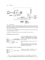
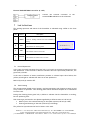
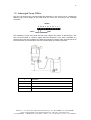
ULTRASONIC HUMIDIFIER USER, INSTALLATION AND MAINTENANCE GUIDE Rev 12.02-EN 2 1 2 3 4 5 6 Package content.................................................................................................. 3 Security measures............................................................................................... 3 Conformity ......................................................................................................... 4 Working principle ............................................................................................... 5 Characteristics .................................................................................................... 5 Installation ......................................................................................................... 5 6.1 Components (UH06-OEM).......................................................................... 5 6.2 Hydraulic connections ................................................................................. 6 6.3 Steam Output............................................................................................... 6 6.4 Electrical connections.................................................................................. 6 6.5 Connections ................................................................................................ 9 6.6 Control System............................................................................................ 9 7 Led Indications ................................................................................................. 10 7.1 Normal Operations .................................................................................... 10 7.2 Tank Cleaning ........................................................................................... 10 8 Alarm Conditions .............................................................................................. 11 8.1 Water Failure .............................................................................................. 11 8.2 Draining System Failure ............................................................................. 11 9 Tank draining .................................................................................................... 11 10 Submerged Pump 220Vac ............................................................................. 12 Elsteam S.r.l - via E.fermi, 496 - 21042 Caronno Pertusella (va) - Tel.+39 02 9659890 - Fax +39 02 96457007 E-mail: [email protected]/[email protected] - Web: http://www.elsteam.com p.iva 01463940120 - c.f.05046150156 - trib.di busto a. 16415-c.c.i.a.a. varese 174164 - cap.soc.i.v. euro 10400,00 3 Please before using your equipment read this guide carefully, by noting all the precautions and safety instructions reported in it. Keep your equipment in good operative conditions. Familiarize with the working and security instructions related to the operation of your apparatus before trying to make it function. Keep this guide and any other booklet provided with your apparatus to be able to refer to them later. 1 Package content Package contains: 2 Ultrasonic Humidifier This User guide A single-phase 220 Vac // 0-14-48 Vac transformer A feed 220V submerged pump (optional) Security measures People who are not familiar with this type of apparatus or which did not read carefully this guide do not have to be authorized to use the humidifier. The humidifier is designed to be used on alternative 220Vac only. Do not try to connect it to a different type of supply. Please ask for different supply voltage. Check that the sector supply voltage corresponds to that of the apparatus. Your humidifier must always be switched-off before any maintenance operations. All operations of maintenance and repairs must be carried out by the manufacturer, his agency or another qualified personnel to avoid any problem. Do not cover any opening of the humidifier and do not insert objects in the openings Elsteam S.r.l - via E.fermi, 496 - 21042 Caronno Pertusella (va) - Tel.+39 02 9659890 - Fax +39 02 96457007 E-mail: [email protected]/[email protected] - Web: http://www.elsteam.com p.iva 01463940120 - c.f.05046150156 - trib.di busto a. 16415-c.c.i.a.a. varese 174164 - cap.soc.i.v. euro 10400,00 4 3 Conformity IL COSTRUTTORE ELSTEAM S.r.l. Azienda Via Enrico Fermi, 496 VA 21042 Indirizzo Cap Provincia Caronno Pertusella Italy Città Stato DICHIARA CHE LA MACCHINA Umidificatore ad ultrasuoni UH Descrizione Modello UH 2008 Serie/Matricola Anno costr. Umidificatore ad Ultrasuoni Denominazione commerciale Umidificazione di ambienti Uso previsto E’ conforme alle direttive comunitarie 2006/95/CEE “Direttiva Bassa Tensione” del Consiglio 27 Dicembre 2006 89/336/CEE “Compatibilità Elettromagnetica EMC” modificata da: - Direttiva 91/263/CEE del Consiglio del 29 aprile 1991 - Direttiva 92/31/CEE del Consiglio del 28 aprile 1992 - Direttiva 93/68/CEE del Consiglio del 22 luglio 1993 - Direttiva 04/108/CEE del Consiglio del 15 dicembre 2004 Claudio Cattaneo Dirigente Responsabile Funzione ELSTEAM S.r.l.- Via E. Fermi 496 – 21042 – Caronno Pertusella (VA) - ITALY Società 2012 Anno Elsteam S.r.l - via E.fermi, 496 - 21042 Caronno Pertusella (va) - Tel.+39 02 9659890 - Fax +39 02 96457007 E-mail: [email protected]/[email protected] - Web: http://www.elsteam.com p.iva 01463940120 - c.f.05046150156 - trib.di busto a. 16415-c.c.i.a.a. varese 174164 - cap.soc.i.v. euro 10400,00 5 4 Working principle The ultrasonic humidifier is an adiabatic humidifier based on the water atomization generated with the vibration of a piezoelectric membrane. The ultrasonic humidifier causes the evaporation of water by generating microscopic water drops negatively ionized. Thanks to the negative ions, the air is purified by precipitation of the pollutants in suspension. These humidifiers are particularly quiet. The humidifier consists of a case, an electronic control board, a draining system, a tank, a fan with speed control and a level detector. The microcontroller based control system performs a cleaning of the water tank at the switch ON and every 6 operating hours. 5 Characteristics Technical Data UH06-OEM UH12-206 UH18-306 UH24-406 Capacity 0,6 l/h 1,2 l/h 1,8 l/h 2,4 l/h Output (diameter) 40 mm 2 x 40mm 3 x 40mm 4 x 40mm Frequency 1.68 MHz nominal Electrical Data Tension Power 220 Vac, 50-60Hz single phase 40VA 80 VA 120 VA 160 VA Hydraulic Data Water pressure 0,5 - 6 bar Inlet Connection 3/4'' Out Connection 1/4'' Mechanical Data Dimensions [mm] LxWxH Weigth [kg] with AC Supply 6 85x126x240 170x126x240 255x126x240 340x126x240 1,7 2,2 2,7 3,2 Installation The humidifier must be installed in a room ventilated and protected, on a vertical surface, plane and rigid. Use the two eyelets of the case and check that the tank is in horizontal position. For multiples units (UH206...UH406) please use at least one eyelet for each unit, to fix humidifier, to prevent lateral forces that may cause breakage of the tank. The mains transformer can be installed remotely. 6.1 Components (UH06-OEM) Elsteam S.r.l - via E.fermi, 496 - 21042 Caronno Pertusella (va) - Tel.+39 02 9659890 - Fax +39 02 96457007 E-mail: [email protected]/[email protected] - Web: http://www.elsteam.com p.iva 01463940120 - c.f.05046150156 - trib.di busto a. 16415-c.c.i.a.a. varese 174164 - cap.soc.i.v. euro 10400,00 6 6.2 Hydraulic connections Hydraulic connection to the units must be realized with flexible pipes which do not cause an action on the tank to avoid damaging the unit. The hydraulic connections are positioned on the bottom side of the humidifier. Input connection is 3/4" and output is 1/4”. The minimal pressure at the entry of the pump should be lower than 0.5 at maximum flow. 6.3 Steam Output The steam output is positioned in the upper part of the humidifier (top cover). The outlet has a diameter of 40mm. To avoid the release of micro-droplets of water by the output should be installed a distribution ramp of 40 cm minimum. The ramp can be made of PVC or other material (as required by the application). In case you can not install a ramp of 40 cm at the exit you can install a double stitched at 90° to create a trap for micro-drops. 6.4 Electrical connections All work concerning electrical installations WILL HAVE to be carried out exclusively by qualified personnel (ex electricians or technicians laying out from a suitable formation). The customer IS responsible for the adequacy of the personnel used. Please check that power supply is disconnected before any maintenance and installation operation. The person in charge of installation will have to ensure the following points : Size of electrical cables must be appropriate for the maximum current being provided. The power supply cable will have to be protected using an appropriate cable gland. Elsteam S.r.l - via E.fermi, 496 - 21042 Caronno Pertusella (va) - Tel.+39 02 9659890 - Fax +39 02 96457007 E-mail: [email protected]/[email protected] - Web: http://www.elsteam.com p.iva 01463940120 - c.f.05046150156 - trib.di busto a. 16415-c.c.i.a.a. varese 174164 - cap.soc.i.v. euro 10400,00 7 Each connection of terminal will have to be firmly protected by a fixing of cable. Before the beginning of installation (and all operations of maintenance and maintenance without panel) the power supply must be disconnected on all the lines and insured against an involuntary connection! Before making electric connections check that the tension corresponds to those of the humidifier! The electric terminals are positioned inside the apparatus (remove the screws which block the lower panel of the case to reach them). In case the mains transformer is not delivered already connected to the humidifier, please use table below to connect. Mains transformer Connections 220V 0V 0V 12/14V 48/59V 0V Figure 1 14V 48V 0V 220V BLUE cable RED cable VIOLET cable Electronic Board Electronic Board Electronic Board FASTON FASTON Circuit breaker Circuit breaker shows positioning of electrical terminals on the electronic board. Figure 1 - Electronic Board Elsteam S.r.l - via E.fermi, 496 - 21042 Caronno Pertusella (va) - Tel.+39 02 9659890 - Fax +39 02 96457007 E-mail: [email protected]/[email protected] - Web: http://www.elsteam.com p.iva 01463940120 - c.f.05046150156 - trib.di busto a. 16415-c.c.i.a.a. varese 174164 - cap.soc.i.v. euro 10400,00 8 N° Name 1,2 48Vac Description AC Input 48Vac Connect cables from mains transformer (4terminals 0 and 8Vac) 3 T 4,5 14Vac GND AC Input 14Vac Connect cables from mains transformer (terminals 0 and 14Vac) 6 0V External Regulator Reference Voltage 7 REG External Regulator Input Voltage (type 0 ... 10v) or enable signal 8 V+ 9 RTH 10,11 ALRM External Regulator Power Supply (type 4 ... 20mA) External Regulator Input Signal(type 4...20mA) Alarm Output Normally opened. Closed during alarm conditions (Max. 2 A, 48 V). Production Output. 12,13 REQ/ ALIM. PUMP These contacts are opened when the production is stopped. They close when productions is required (Max. 2 A, 48 V). If the submerged pump is used these contacts can be used to switch On/Off the pump (Requires a different firmware) Table 1: Electrical and Control Connections (connector#1 in Fig.1) N° Name Description 1 Vac 48 Vac power supply for nebulizer board 2 3 In Control signal for nebulizer board 4 Table 2 : Nebulizer Board Connections (connector #2 in Fig.1) Elsteam S.r.l - via E.fermi, 496 - 21042 Caronno Pertusella (va) - Tel.+39 02 9659890 - Fax +39 02 96457007 E-mail: [email protected]/[email protected] - Web: http://www.elsteam.com p.iva 01463940120 - c.f.05046150156 - trib.di busto a. 16415-c.c.i.a.a. varese 174164 - cap.soc.i.v. euro 10400,00 9 6.5 Connections 6.6 Control System The terminals of control and alarm signals are located on the electronic control board (connector 1 – see Figure 1 - Electronic Board) (remove the lower panel of the case to reach them). The openings for the cables are located on the lower side of the case. Use cables with a section of max. 1sqmm. The electronic controller embedded can use an external signal (from an external controller) or internal proportional controller. According to the operating process chosen, select suitable connection in the list. Embedded Proportional Controller To use the embedded proportional controller connect the humidity probe (4… 20 my) as indicated in the schematic. The humidity probe must be installed in the room or conduit to be controlled. If the enable signal is not used connect V+ et REG Use R13 potentiometer on the control board to regulate the request of humidity (0% clockwise and 100% counter-clockwise) External ON/OFF controller or Humidistat Connect the external Controller to the terminals REG and V+ as in the schematic Elsteam S.r.l - via E.fermi, 496 - 21042 Caronno Pertusella (va) - Tel.+39 02 9659890 - Fax +39 02 96457007 E-mail: [email protected]/[email protected] - Web: http://www.elsteam.com p.iva 01463940120 - c.f.05046150156 - trib.di busto a. 16415-c.c.i.a.a. varese 174164 - cap.soc.i.v. euro 10400,00 10 External PROPORTIONAL controller (0..10V) Connect the external Controller to the terminals REG and 0V as in the schematic 7 Led Indications The working operation and status of the humidifier is indicated using 4 LEDs on the front panel. Pos Colours Description IN OPERATION 1 GREEN 2 RED If fixed or blinking indicates that the humidifier is working. TANK CLEANING If ON indicates the cleaning phase FAN FAILURE. 3 RED If ON indicates a failure on the FAN LOW WATER LEVEL 4 7.1 YELLOW If ON indicates low water level in the tank Normal Operations In the case of normal operation the green led (1) is lit with an intensity proportional to the mist production. If the external or internal controller does not require mist production, the green led (1) blinks. In the case of absence of water (insufficient pressure or solenoid input valve failure) the yellow (4) led light to indicate that there is no mist production. Red led (2) and (3) must be OFF. 7.2 Tank Cleaning The microprocessor based control system, performs automatic tank cleaning at start-up and every 6 hours of operation. This cleaning phase allows limestone deposit to be eliminated from the tank. During this cleaning phase green led (1) blinks to indicate that the humidifier is working, but not producing mist. Tank cleaning is performed in two phases signalled by a different state of red led (2): Water input in the tank and starting of the siphon system (red led (2) is ON) Cleaning and draining of the tank (red led (2) is blinking) The yellow led (4) indicates the level of water in the tank. Elsteam S.r.l - via E.fermi, 496 - 21042 Caronno Pertusella (va) - Tel.+39 02 9659890 - Fax +39 02 96457007 E-mail: [email protected]/[email protected] - Web: http://www.elsteam.com p.iva 01463940120 - c.f.05046150156 - trib.di busto a. 16415-c.c.i.a.a. varese 174164 - cap.soc.i.v. euro 10400,00 11 8 Alarm Conditions In case of failure the micro-controller based board stops mist production and water input. After a wait period of 5 minutes the humidifier automatically start with tank cleaning phase. During the stop phase green led (1) is OFF, red led (3) could signal FAN failure; red led (2) and yellow led (4) identify the failure. 8.1 Water Failure This failure is signalled with yellow led (2) blinking and green led (1) OFF. 8.2 Draining System Failure Draining system failure during tank cleaning phase. The causes of this failure can be a problem with draining solenoid valve or an obstruction in the draining system (pipes). This failure is signalled with red led (2) blinking and green led (1) OFF. 9 Tank draining When the humidifier is not used is mandatory to execute a manual draining. To complete this operation execute following steps: 1. 2. 3. 4. 1. 2. 5. Close input valve Switch OFF the unit Switch ON the unit Wait until tank is empty Green LED blink Yellow LED is ON Switch OFF the unit Elsteam S.r.l - via E.fermi, 496 - 21042 Caronno Pertusella (va) - Tel.+39 02 9659890 - Fax +39 02 96457007 E-mail: [email protected]/[email protected] - Web: http://www.elsteam.com p.iva 01463940120 - c.f.05046150156 - trib.di busto a. 16415-c.c.i.a.a. varese 174164 - cap.soc.i.v. euro 10400,00 12 10 Submerged Pump 220Vac The unit can operate with a pump feeding the humidifier. In the case of use of a submerged 220Vac pump, power supply of the pump must be carried out according to the following schematic. Bornier #1 13 12 11 10 9 8 7 6 5 4 3 2 1 220 Vac ~ Pompe The installation of the pump with the tank must respect the outline of below figure. The tank can be installed in a position higher than the humidifier. If the tank is installed in a position lower than the humidifier the difference between solenoid valve and the bottom of the tank should not exceed 60cm with the standard pump provided by Elsteam. 1 Humidifier 2 Solenoid valve (optional) 3 Flexible pipe 4 Pump 5 Tank Elsteam S.r.l - via E.fermi, 496 - 21042 Caronno Pertusella (va) - Tel.+39 02 9659890 - Fax +39 02 96457007 E-mail: [email protected]/[email protected] - Web: http://www.elsteam.com p.iva 01463940120 - c.f.05046150156 - trib.di busto a. 16415-c.c.i.a.a. varese 174164 - cap.soc.i.v. euro 10400,00