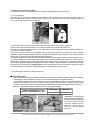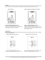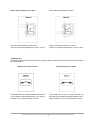
1
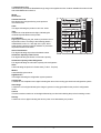
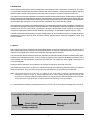
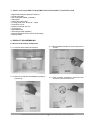
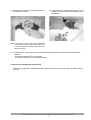
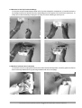
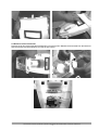
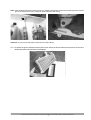
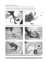
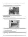
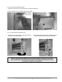
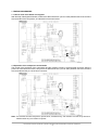
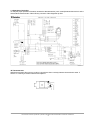
LÍDER MUNDIAL EM ELETRODOMÉSTICOS
SERVICE MANUAL
REFRIGERATOR DF36
MODULE I
TABLES AND SPECIFICATIONS
REVISION 0
CONTENTS
1. GENERAL INFORMATION ................................................................................................................. 3
1.1 Produced Model ............................................................................................................................... 3
1.2 Commercial Code Description .......................................................................................................... 3
1.3 Identification Tag ............................................................................................................................... 4
2. PRODUCT SPECIFICATIONS ........................................................................................................... 5
3. COMPONENTS SPECIFICATIONS ................................................................................................... 6
4. COOLING FLUID CIRCULATION SCHEMATIC DIAGRAM ................................................................ 7
5. COLD AIR FLOW SCHEMATIC DIAGRAM ....................................................................................... 8
6. OPERATION ...................................................................................................................................... 9
6.1 Defrost ........................................................................................................................................ 9
6.2 Compensation in Case of Power Failure .................................................................................... 10
This document cannot be reproduced or passed to third parties without authorization from Electrolux do Brasil S.A.
2
1. GENERAL INFORMATION
1.1 Produced Model
FROST FREE REFRIGERATOR
MODEL
COMMERCIAL
CODE
Frost Free Refrigerator DF36
02344FEA306
02344FUA306
02344FFA306
02344FDA306
02344FHA306
02344F6A206
02344FQA106
MODEL
CODE
PNC
PRODUCTION
START
DF36
925026275
925026278
925026279
925026280
925026281
925026282
925026283
June/2004
1.2 Commercial Code Description
The commercial code is printed in an identification tag localized inside the refrigerator cabinet (left side) containing
the following data:
a. Product line:
02 – Two door refrigerator Curitiba unit
e. Voltage/frequency:
1 - 127V/60Hz
2 - 220V/60Hz
3 - 220V/50Hz
b. Capacity:
34 – 346 liters
f. Product versiob:
A – 1st version
B – 2nd version
C – 3rd version and so on
c. Number and type of doors:
4 – door with right opening
d. Produc type:
F – Frost Free
g. Market:
Indicates whether the product is for the
internal market (B) or the external one
(another letter or number).
02 34 4 F E A 3
a. Product line
e. Voltage/frequency
b. Capacidaty (liters)
f. Product version
c. Right opening door
g. Market
d. Product type
Example:
02 – Two doors refrigerator (combined) Curitiba unit
34 – 346 liters
4 – Hinges on the left side
F – Frost Free
E – Argentinean market
A – Version A (1st version)
3 – 220V/50Hz
Note: The example above only shows how to identify in the tag the code field.
This document cannot be reproduced or passed to third parties without authorization from Electrolux do Brasil S.A.
3
1.3 Identification Tag
The Electrolux products are identified through a tag on the appliance which contains valuable information for the
Authorized Maintenance Service.
06
42812345
VOL. TOTAL BRUTO
346
VOL. ESTOC. CONG.
70
CLASSE MERCADO
TE
VOL. ESTOC REFRIG. PRESSÃO DE ALTA - BAIXA
Serial Number
Eight digits indicating the year, week of production and a
sequential number, according to the following pattern =
YWWSSSSS, where Y = last digit of the year; WW =
week when the product was built; SSSSS = a production
sequential number for the week.
276
GAS FRIGOR.
R134a
CORRENTE
1,1A
175,0 - -3,0 psig
CARGA DE GAS
110g
POTENCIA
123W
FAIXA TENSAO
198 - 242 V~
Gross Total Volume
Four digits indicating the product’s declared volume.
CAPACID. CONG.
ELC
NORMA
5155
RESIST. DESCONG.
FREQUENCIA
50
6,0 kg/24h
42812345
Nº DE SERIE
COR
Nº DE SERIE
Type
A maximum of 60 alphanumeric digits, indicating the
model and specifications of the product.
02344FEA306
REFRIGERADOR DUAS
PORTAS DOMÉSTICO
CÓDIGO COMERCIAL
02344FEA3
TIPO
220 V~ DF36 E
Color
Two digits indicating the product’s color: 06 - white
MODELO
CÓDIGO COMERCIAL
DF36
TENSÃO
MODELO
50
ELECTROLUX DO BRASIL S.A
CURITIBA - PR - INDUSTRIA BRASILEIRA
C.N.P.J. 76.487.032.0001-25
PROCESSO INTERNO
Commercial Code
Nine alphanumeric digits referring to the product’s
commercial code.
MERCADO
Model
Model DF36
Volumetric Capacity of the Freezer
Four digits indicating the freezer’s volumetric capacity.
Volumetric Capacity of the Refrigerator
Four digits indicating the volumetric capacity of the refrigerator.
Class
Letter indicating the product’s climate class (T class - Tropical).
Market
Letter identifying the market.
High Pressure
Three digits indicating the refrigeration system pressure.
Cooling Gas
A maximum of five alphanumeric digits indicating the name of the cooling gas used in the refrigeration system.
Gas Charge
A maximum of four digits indicating the charge in grams of cooling gas loaded in the product’s refrigeration
circuit.
Current
This field contains a maximum of two digits followed by one decimal indicating the product’s working current.
Potency
A maximum of four digits indicating the electric power to be absorbed by the product.
This document cannot be reproduced or passed to third parties without authorization from Electrolux do Brasil S.A.
4
2. PRODUCT SPECIFICATIONS
MODEL CODE
D F 36
TYPE
REFRIGERATOR / FREEZER
TWO DOORS
PRODUCT DIMENSIONS
(mm)
WIDTH
600
DEPTH
745
HEIGHT
PACKAGED PRODUCT
DIMENSIONS
(mm)
1725
WIDTH
640
DEPTH
760
HEIGHT
NOMINAL CAPACITY
(litros)
1775
FREEZER
70
REFRIGERADOR
276
TOTAL
346
FREEZING CAPACITY
6 kg/24h
NET WEIGHT (kg)
66
GROSS WEIGHT (kg)
68
REFRIGERANT GAS
R134a
GAS CHARGE (g)
110 ± 5
ELECTROMECHANIC TIMER (EVERY 8
HOURSOF COMPRESSOR
OPERATION)
DEFROST
HIGH PRESSURE (psig)
210 (STABILIZED REGIME
PRESSURE)
LOW PRESSURE (psig)
-1 (STABILIZED REGIME PRESSURE)
CLASSIFICATION
POWER CONSUMPTION
(kWh/MONTH)
3 STARS
127/220V - 60Hz
55,6
220V - 50Hz
37,9
INTERNAL LAMP
(15W)
1 IN THE REFRIGERATOR
PARTS & ACCESSORIES
PRODUCT
LEVELING
2 FRONT LEGS
This document cannot be reproduced or passed to third parties without authorization from Electrolux do Brasil S.A.
5
3. ESPECIFICAÇÕES DE COMPONENTES
MODEL
D F 36
02344FQA106
02344F6A206
02344FEA306
02344FUA306
02344FFA306
02344FDA306
02344FHA306
VOLTAGE (V) / FREQUENCY (Hz)
127 / 60
220 / 60
220 / 60
VOLTAGE RANGE (V)
103 - 135
198 - 242
198 - 242
POTENCY (W)
133
130
123
CURRENT (A)
2,0
1,0
1,1
EG 75HLR
EG 75HLR
EG 75HLR
COMMERCIAL CODE
MODEL
R
E
F
R
C
Y
C
L
E
START TYPE
COMPRESSOR
AMPERIMETRIC RELAY
OIL TYPE
ISO 10
RESISTANCE AT AUXILIARY
+25ºC
MAIN
7,1
43,10
2,8
10,35
EVAPORATOR
FLAP TUBE
CONDENSER
EXTERNAL
DRYING FILTER
10,35
MOLECULAR SIEVE (XH9 - 19g)
CAPILLARY PIPE
I.D. 0,75 x 2490mm
CAPACITY
120 / 240 VAC FLA6 LRA 36
THERMOSTAT
MODEL
TSV 5001-09
OPEN AT 25ºC ± 3ºC
CLOSE AT -6ºC ± 4ºC
DEFROST THERMOSTAT (BIMETAL) N14 KSD 303A
E
L
E
C
T
R
I
C
72ºC ± 4ºC
COMPRESSOR CLOSING TEMPERATURE(ºC)
THERMAL
PROTECTOR OPENING TEMPERATURE (ºC)
70 - 52
70 - 52
70 - 52
110 - 120
100 - 110
100 - 110
8
8
8
107
377
377
POTENCY (W)
255 ± 7,5
255 ± 7,5
255 ± 7,5
RESISTANCE (Ω) AT 23ºC
57,9 - 70,3
180,8 - 210,9
180,8 - 210,9
14
14
14
1152 ± 5%
3457 ± 5%
3457 ± 5%
15
15
15
POTENCY (W)
MOTORFAN
D
E
T
A
I
L
S
A C 250V / 10A
DEFROST
CAPACITY AND OPERATION
THERMAL FUSE TEMPERATURE
DEFROST
RESISTANCE
GUTTER
RESISTANCE
RESISTANCE (Ω) AT 25ºC
POTENCY (W)
RESISTANCE (Ω) AT 25ºC
LAMP POTENCY (W)
DOOR SWITCH
250V / 0,5A
11.800Ω ±
2.360Ω
ELECTROMECHANIC TIMER (RESISTANCE) AT
25ºC
NOT MEASURABLE WITH A
OMMETER
This document cannot be reproduced or passed to third parties without authorization from Electrolux do Brasil S.A.
6
4. COOLING FLUID CIRCULATION SCHEMATIC DIAGRAM
Compressor – Evaporation Coil - Condenser – Dehumidifier Pipe – Drying Filter – Capillary Pipe - Evaporator –
Suction Accumulator – Suction Line - Compressor
Evaporator
Suction line
Dehumidifier
pipe
Condenser
Capillary pipe
Drying filter
Compressor
Evaporation coil
This document cannot be reproduced or passed to third parties without authorization from Electrolux do Brasil S.A.
7
5. COLD AIR FLOW SCHEMATIC DIAGRAM
The cold air generated in the evaporator is forced into the freezer
compartment and into the refrigerator compartment by the
motofan.
In the freezer compartment the cold air is distributed through
the top flow to the shelves and the food is frozen by the cold
air flow.
In the refrigerator compartment, the cold air flow coming from
the evaporator is carried by the freezer’s top flow passing
through the manual damper that will control the amount (flow
rate) of cold air that will be redirected to cool down the
refrigerator compartment.
The manual damper has three positions:
· Maximum Refrigerator: 80% of the air flow rate is
redirected to the refrigerator implying in a faster cooling
rate in the refrigerator compartment.
· Normal: 50% of the air flow rate is redirected to the
refrigerator.
· Maximum Freezer: only 20% of the air flow rate is
redirected to the refrigerator thus implying in a slower cooling
rate in the refrigerator compartment.
Refrigerator's air
return
(detail)
Refrigerator's air
return
After passing through the manual damper, the cold air flow
will be carried through a space in the intermediary division
between the freezer and the refrigerator compartments to the
top flow duct of the refrigerator that will then uniformly distribute
it through that compartment.
After cooling down the refrigerator compartment the air will
return through the refrigerator’s Top Flow back, which will direct
it through another space in the intermediary division between
the freezer and refrigerator compartments, to the freezer’s
evaporator.
Motorfan
Cover with
air outlets
Evaporator
Multiflow Freezer
Air outlets
Freezer's
Top Flow
Air return
Refrigerator's
Top Flow
Detail of Refrigerator's Air return
This document cannot be reproduced or passed to third parties without authorization from Electrolux do Brasil S.A.
8
6. OPERATION
The DF36 Electromechanical Frost Free refrigerator works under the vapor compression cycle R134-a. The vapor
is compressed in the alternate compressor, release heath in the condenser, is restricted into the capillary pipe and
absorbs heath in the flap tube evaporator, returning to the compressor as vapor through the suction line.
The cold air coming form the evaporator is forced by the motofan into the freezer and then conducted to the refrigerator
through the freezer and refrigerator top flow ducts. The temperature control in the refrigerator is done with the help of an
electromechanical thermostat located inside the top flow of this compartment which, in accordance to the temperature,
varies its diaphragm turning off or on the power for the compressor, timer, and evaporator motofan.
The temperature in the freezer compartment depends on the thermostat localized inside the refrigerator compartment
which will be controlling the temperature of that compartment. As the refrigeration need of the refrigerator compartment
is greater than the one of the freezer compartment, having the temperature control located in the refrigerator
compartment guarantees that the freezer will always be operating in an adequate temperature (below -18ºC).
A greater refrigeration speed between the both compartments can be controlled through the mechanical damper
localized in the freezer’s top flow, which has three possible, adjust positions: maximum refrigerator, normal, and
maximum freezer.
6.1 Defrost
After cooling for some time, all the humidity introduced inside the product by the stored food, or by the opening of the
doors, will be retained in the evaporator and will gradually freeze. At that point, it will be necessary to remove this ice
in excess accumulated on the surface of the evaporator, through a defrost operation.
The product has a defrost resistance fixed to the evaporator and another resistance fixed to the defrost drain gutter,
localized in the refrigerator’s top flow, so as to prevent the freezing of the gutter thus facilitating the draining of the
water resulting from the defrost that comes from the evaporator. The evaporator and the gutter resistances’ are
connected in parallel.
During the defrost operation, the compressor, the motofan and the timer will remain turned off.
The resistances are turned on by the timer, with the monitoring of the defrosting end being done by the defrost
thermostat (bimetal). There is a thermal security fuse positioned in the up right side of the evaporator.
Note: The thermal fuse works in the case of a failure in one of the other circuits thus avoiding the defrost
resistance to heat too much. In case the thermal fuse is used it will be spoiled. Before replacing that
component, it’s mandatory that the problem that led to its use should have been identified and fully corrected.
The product must never be turned on without the thermal fuse being correctly installed.
6.1.1 Defrost Bimetal registering a temperature equal to or above +25°C ( ±3ºC) when the refrigerator is turned on:
Accumulates 8 hours of compressor operation
Pause (10min)
(dripping with the resistances
already turned off)
Defrost (up to +25ºC in the
Bimetal)
This document cannot be reproduced or passed to third parties without authorization from Electrolux do Brasil S.A.
9
6.1.2 Defrost Bimetal registering a temperature less than -6ºC (±4ºC) when the refrigerator is turned on (in the
case of a power failure happening before the product has achieved a temperature above +25ºC (3 ºC) in the
defrost bimetal).
Accumulates 8 hours, considering the time
accumulated befor the turn off
Pause (10min)
(dripping with the resistances
already turned off)
Defrost (up to +25ºC in the
Bimetal)
6.1.3 During the continuous operation of the refrigerator
Accumulates 8 hours
of compressor operation
Defrost (up to +25ºC in the
Bimetal)
Pause (10min)
(dripping with the resistances
already turned off)
6.2 Compensation in Case of Power Failure
In case of power failure, the product will behave according to the following conditions once the power returns.
6.2.1 Defrost Bimetal registering a temperature equal to or above +25ºC
The product will restart operation according to the procedure in item 6.1.1.
6.2.2 Defrost Bimetal registering a temperature lesser than -6ºC
The product will preserve the same adjustment configuration it has before the power failure. The defrost will happen
according to item 6.1.2.
ELECTROLUX DO BRASIL S.A.
Rua Ministro Gabriel Passos, 360
Caixa Postal 16201 CEP 81 520900
Curitiba Paraná Brasil
Tel/Fax (041) 371 7000
http://disc.electrolux.com.br
Customer Care Center
Elaboration: Service Engineering
July/2004
Revision 0
This document cannot be reproduced or passed to third parties without authorization from Electrolux do Brasil S.A.
10
LÍDER MUNDIAL EM ELETRODOMÉSTICOS
SERVICE MANUAL
REFRIGERATOR DF36
MODULE II
ASSEMBLING AND DISASSEMBLING OF THE REFRIGERATOR/FREEZER
REVISION 0
CONTENTS
1. TOOLS AND EQUIPMENT REQUIRED FOR THE PRODUCT MAINTENANCE ......................................... 3
2. DISASSEMBLING OF THE FREEZER ......................................................................................................
2.1 Access to the Freezer Components ....................................................................................................
2.2 Access to the Refrigerator Components ..............................................................................................
2.3 Removal of the Top Flow Assemblage .................................................................................................
2.4 Removal of the Air Duct and Gutter .....................................................................................................
2.5 Removal of the Thermostat ..................................................................................................................
2.6 Disassembling of the Door Handle .......................................................................................................
2.7 Removal of the Doors ..........................................................................................................................
2.8 Replacement of the Motofan ................................................................................................................
2.9 Disassembling of the Evaporator .........................................................................................................
3
3
4
5
5
6
8
8
9
10
2.10 Removal of the Timer ......................................................................................................................... 12
This document cannot be reproduced or passed to third parties without authorization of Electrolux do Brasil S.A.
2
1. TOOLS AND EQUIPMENT REQUIRED FOR THE PRODUCT MAINTENANCE
• Digital multimeter plier (Minipa ET 3200 A)
• Curved-noose plier
• Pipe-cutting plier (LRSZ –VULCAN))
• Cutting plier
• Lokring plier (VULCAN)
• Lockring joints 8 to 6, aluminum - copper
• Screwdriver 1/4 x 6”
• Phillips screwdriver 3/16 x 6"
• Torx tools set
• Digital Multimeter
• Thermal-hygrometer (SUNDO)
• Digital Thermometer with 4 sensors (Full Gauge)
• Lokprep sealant
2. PRODUCT DISASSEMBLING
2.1 Access to the Freezer Components
2.1.1 Remove all the freezer accessories.
2.1.2 With a Phillips screwdriver, remove the top flow
screws.
2.1.3 Remove the top flow assemblage by pulling it
from the top.
2.1.4 With a Phillips screwdriver, remove the two
screws so as to loose the cover.
This document cannot be reproduced or passed to third parties without authorization of Electrolux do Brasil S.A.
3
2.1.5 Pull the cover as shown in the image below and
disconnect the motofan.
2.1.6 Disconnect the motofan thermostat – it has a
locking connector that should be pressed so as to
be released.
Note.: The removal of this cover can be hindered if
the product is cold since then the ice can stuck
it to the evaporator. Await a few minutes to
remove the cover.
2.1.7 To assemble the components above just follow the assembling sequence backwards, with special care in
relation to:
- the proper positioning of the components,
- the correct connection of the electrical terminals.
2.2 Access to the Refrigerator Components
Remove the refrigerator compartment shelves, pulling them to the front until they stop. Raise them and pull
them out.
This document cannot be reproduced or passed to third parties without authorization of Electrolux do Brasil S.A.
4
2.3 Removal of the Top Flow Assemblage
To remove the top flow assemblage located on the top of the refrigerator compartment, you should remove the
two Phillips screws and carefully loose the assemblage from its supports in the back of the internal box. To
finally remove the assemblage, unplug the six ways connector releasing its security lock.
2.4 Removal of the Air Duct and Gutter
To remove the air duct, unplug the terminals of the thermostat and the light bulb, unlock the gutter from the top
flow cover and pull the air duct up (see images bellow and on the next page).
This document cannot be reproduced or passed to third parties without authorization of Electrolux do Brasil S.A.
5
2.5 Removal of the Thermostat
Remove the air duct and pull the thermostat button out of the top flow. Release the thermostat from the fasteners
that hold its body and spiral bulbous from the top flow casing.
This document cannot be reproduced or passed to third parties without authorization of Electrolux do Brasil S.A.
6
Note: when replacing the thermostat by a new one, please pay attention to the bulbous fastening to the vertical
groove on the top flow cover, locking the spiral bulbous in the casing.
Attention: do not remove the plastic coat that covers the bulbous.
2.5.1 To replace the gutter resistance with the internal net, detach the ribbon that fixes the net to the air duct and
release the top flow internal net from the fasteners.
This document cannot be reproduced or passed to third parties without authorization of Electrolux do Brasil S.A.
7
2.6 Disassembling of the Door Handle
2.6.1 With the help of a screwdriver, remove the handle cover applying pressure from below so as not to scratch
the surface. Pull the cover to the front, releasing it.
2.6.2 With the help of a Torx T30 tool, remove the screw and release the handle pulling it to the left to release the
lock, and then to the front.
2.6.3 To assemble the door handle, please follow the same sequence previously described backwards.
Note: whenever necessary to replace the handle, it’s also recommended to replace the handle cover since it can
be damaged during the removal.
2.7 Removal of the Doors
2.7.1 Using a 1/4 x 6" Phillips screwdriver, loosen the two screws of the top hinge, and then lift the front part of the
hinge so as to unfit it.
2.7.2 Carefully remove the freezer door, lifting and
unfitting it from the intermediary hinge. Be careful
not to lose the support plastic washer.
2.7.3 Using a T30 Torx tool, remove the intermediary
hinge loosening its screws.
2.7.4 Remove the refrigerator door, lifting it and unfitting
it from the bottom hinge.
This document cannot be reproduced or passed to third parties without authorization of Electrolux do Brasil S.A.
8
2.8 Replacement of the Motofan
2.8.1 Follow the procedure described in item 2.1, Access to the Freezer Components.
2.8.2 With a cutting pliers, cut the fasteners that fix the motofan net on the evaporator cover.
2.8.3 With a needle-nose pliers, remove the propeller lock so as to release the propeller.
2.8.4 Remove the Phillips screw from the motofan cover and, with the help of a screwdriver, release the locks.
2.8.5 Remove the motofan motor.
To re-assemble the motofan assemblage, please follow the same procedure backwards, using new fasteners to fix
the electric cabling to the evaporator cover. Make sure that the motofan axle seals are correctly positioned.
This document cannot be reproduced or passed to third parties without authorization of Electrolux do Brasil S.A.
9
2.9 Disassembling of the Evaporator (bimetal, thermal fuse and defrost resistance replacement)
Evaporator Replacement (procedure for products outside the warranty period)
2.9.1 Follow the procedure described in item 2.1, Access to the Freezer Components.
2.9.2 Loosen the two Phillips screws that fix the evaporator to the internal box.
Attention:
Be careful not to drop the screws in the gutter bellow the evaporator or in the damper duct.
If anything falls into one of these two components, it should be necessarily removed so as to preclude any
operation failures with the product.
2.9.3 Collect the cooling gas (in case there is any in the unit).
2.9.4 Remove the rubber shock absorber form the suction line and, with the help of a LRSZ pliers, cut the pipes of
the suction and the capillary lines next to the lockring ring.
2.9.5 Put the anaerobic Lokprep sealant in the suction/capillary lines pipes and in the entry and exit accesses of
the evaporator.
2.9.6 Use the lockring joint to connect the evaporator pipe to the suction/capillary line. Uphold the evaporator to
assure a pre-assembling with the joints.
2.9.7 With the help of a lockring pliers, close the lockring joints.
2.9.8 Pressurize the system with 120 lbf/pol2 so as to check if there are any leaks in the joints or in the accessible
parts of the sealed unit.
2.9.9 No leaks being observed, re-operate the sealed unit.
This document cannot be reproduced or passed to third parties without authorization of Electrolux do Brasil S.A.
10
2.9.10 To remove the Reflecting Gutter:
• Unplug the connectors of the fuse-bimetal circuit and the resistance.
• Pull the evaporator locks to release the reflecting gutter.
2.9.11 To replace the fuse-bimetal circuit:
• Carefully turn the evaporator from the right to the left,
as shown in the picture bellow.
• Using a cutting pliers, remove the four plastic fasteners
that fix the fuse-bimetal circuit to the evaporator.
INSTALL THE NEW FUSE-BIMETAL CIRCUIT TAKING CARE TO POSITION IT THE SAME
WAY THE ORIGINAL CIRCUIT WAS POSITIONED. FIX THE NEW CIRCUIT WITH PLASTIC
FASTENERS CUTTING OFF THE EXCESS.
This document cannot be reproduced or passed to third parties without authorization of Electrolux do Brasil S.A.
11
2.9.12 To replace the defrost resistance:
• Release the metal fastener that fixes the resistance
under the evaporator.
• Release the resistance from the evaporator fittings.
To install a new resistance, fit it in the evaporator
fittings and then fix it with the metal fastener.
2.10 Removal of the Timer
2.10.1 With the help of a Phillips screwdriver, loosen the screw that fixes the box which contains the timer.
2.10.2 Carefully remove the box, unfitting it from the internal lateral side of the cabinet.
2.10.3 With a screwdriver, loosen the three fixing locks in the box so as to have access to the timer. To remove the
timer, just remove the three screws fixing it to the box.
ELECTROLUX DO BRASIL S.A.
Rua Ministro Gabriel Passos, 360
Caixa Postal 16201 CEP 81 520900
Curitiba Paraná Brasil
Tel/Fax (041) 371 7000
http://disc.electrolux.com.br
Customer Care Center
Elaboration: Service Engineering
July/2004
Revision 0
This document cannot be reproduced or passed to third parties without authorization of Electrolux do Brasil S.A.
12
LÍDER MUNDIAL EM ELETRODOMÉSTICOS
SERVICE MANUAL
REFRIGERATOR DF36
MODULE III
ELECTRICAL COMPONENTES TESTING
REVISION 0
CONTENTS
1. TESTING PROCEDURES .........................................................................................................................
1.1 How to know if the board is energized ...............................................................................................
1.2 Operation of the compressor and motofan .........................................................................................
1.3 Operation of the bulbs .......................................................................................................................
1.4 Operation of the defrost system ........................................................................................................
3
3
3
4
5
2. ELECTRICAL COMPONENTS TESTING PROCEDURES .........................................................................
2.1 Compressor ......................................................................................................................................
2.2 Thermostat .......................................................................................................................................
2.3 Timer ................................................................................................................................................
2.4 Switch Test .......................................................................................................................................
2.5 Bimetal Test ......................................................................................................................................
7
7
7
8
8
9
This document cannot be reproduced or passed to third parties without authorization of Electrolux do Brasil S.A..
2
1. TESTING PROCEDURES
1.1 How to know if the board is energized
With the help of the digital multimeter, measure the alternate tension (127V or 220V) between the brown and blue
wire terminals of the compressor, as indicated in the scheme below:
1.2 Operation of the compressor and motofan
The control of the operation of the compressor and the motofan is done by the thermostat and timer. After the
product is connected to the mains, verify if there is alternate tension (127V or 220V) between the brown and blue
wire terminals and the pin 4 of the timer connector.
Note: The motofan and the compressor operate both, simultaneously. The motofan is turned off by the doors
switches when any one of them is opened.
This document cannot be reproduced or passed to third parties without authorization of Electrolux do Brasil S.A..
3
1.3 Operation of the bulbs
To verify the proper operation of the bulb, measure the alternate tension (127V or 220V) between the terminal 1 of the
thermostat and the terminal 4 of the multi-way connector of the refrigerator top flow.
! Thermostat test
With the thermostat in the turned on position, it should have been continuity between the terminals 1 and 3. If
there is no continuity, the thermostat must be replaced.
This document cannot be reproduced or passed to third parties without authorization of Electrolux do Brasil S.A..
4
1.4 Operation of the defrost system
To check the operation of the product defrost system the steps bellow should be followed:
1.4.1 Forced Defrost
With the help of a screwdriver, turn the timer mechanism in the clockwise sense until you hear the first click, so
as to manually advance it to the defrost position. At this point, a change occurs in the timer contacts going from
1-4 to 1-2, turning off the product compressor.
1.4.2 Verify if there was change of the timer contacts which provide energy for the resistances.
Now, there should be alternate tension (127 or 220V) between the contacts 1-2 of the timer.
The freezer temperature being bellow -6 ± 4ºC, there will be current feeding the defrost and gutter resistances,
which are connected in parallel.
At this point, the timer motor stops, because being serially connected to the resistances it has an elevated
impedance (approximately 16.000) in relation to the parallel value between the resistances. The current that flows
through the circuit tend to follow the path with lesser resistance.
The defrost operation is monitored by the bimetallic defrost thermostat. When the temperature achieves +25 ± 3
º
C in the thermostat, its contact opens interrupting the current being passed to the resistances. At this point, the
timer motor is energized again, resuming operation and turning the timer mechanism for 10 minutes. During this
period of time, the product is still with contacts 1-2 on and the motofan, resistances and the compressor are turned off.
We call this 10 minutes period of dripping time. After this period of time, there is a change in the timer contacts
to 1-4, activating the compressor if the refrigerator thermostat is requiring its activation.
1.4.3 Checking the resistances with forced defrost
! Defrost Resistance
Disconnecting the freezer evaporator defrost resistance male connector, using the resistance scale of the multimeter,
it is possible to verify its resistance value in ohms (see the table bellow for comparison values).
In the resistance female connector located in the cabinet, it is possible to measure the alternate tension127V
or 220V), if the defrost is activated, according to the procedure described above. If there is tension in this
connector, that means that the thermal fuse and the defrost thermostat are allowing the defrost operation.
térmico e o termostato de degelo estão permitindo a operação de degelo.
OHMIC RESISTANCE OF THE
DEFROST RESISTANCE AT +23ºC
FOR 127V
FOR 220V
57,9 to 70,39
180,8 to 210,9
BRIDGE BETWEEN
THE CONNECTORS*
RESISTANCE MEASUREMENT
POWER VOLTAGE
MEASUREMENT WITH
DEFORST IN OPERATION
* Attention: The bridge (pink
wire) between the evaporator
resistance and the bimetal-fuse
connectors should present
continuity between them,
otherwise there won’t be
current to feed the defrost
resistance.
This document cannot be reproduced or passed to third parties without authorization of Electrolux do Brasil S.A..
5
! Gutter Resistance
In the multi-way connector, located in the refrigerator top flow, it is possible to measure the ohmic resistance the
tension of the current being fed to the gutter resistance.
1. In the refrigerator top flow male connector, measure the value of the ohmic resistance of the gutter resistance
positioning the probing needles of the multimeter, already set to the resistance scale, on the terminals 5-6.
OHMIC RESISTANCE OF THE
GUTTER RESISTANCE AT +23ºC
1
2
3
6
5
4
FOR 127V
FOR 220V
1094 to 1210
3284 to 3630
TOP FLOW MULTI-WAYS MALE
CONNECTOR
2. In the top flow female connector, next to the cabinet, it will be possible to measure the alternate tension (127V
or 220V) of the current being fed to the gutter resistance on terminals 5-6, while the product is defrosting.
1
2
3
6
5
4
TOP FLOW MULTI-WAYS
FEMALE CONNECTOR
1.4.4 Checking the thermal fuse and the defrost thermostat
With the digital multimeter adjusted to the continuity scale, check the thermal fuse and bimetal thermostat
connector for the following points:
IN TERMINALS 2-4 THERE SHOULD BE CONTINUITY TO
GUARANTEE THE PROPER OPERATION OF THE THERMAL FUSE.
2
4
1
3
THERE SHOULD BE CONTINUITY BETWEEN TERMINALS 1-3 IF THE
TEMPERATURE IN THE BIMETAL DEFROST THERMOSTAT IS BELOW
-6°C WITH A VARIATION OF ±4°C.
THERE WON’T BE CONTINUITY BETWEEN TERMINALS 1-3 IF THE
TEMPERATURE IN THE BIMETAL DEFROST THERMOSTAT IS ABOVE
+25°C WITH A VARIATION OF ±3°C.
This document cannot be reproduced or passed to third parties without authorization of Electrolux do Brasil S.A..
6
2. ELECTRICAL COMPONENTS TESTING PROCEDURES
2.1 Compressor
Measure the terminals (C, S e R) with the digital multimeter set to the lesser scale of ohmic resistance, with the
compressor at 25ºC.
127V/60Hz
220V/50-60Hz
Between R and C
2,8
10,35
Between S and C
7,1
43,1
Between S and R
9,9 approx.
53,5 approx.
2.2 Thermostat
Measure, with the help of the digital multimeter set to the continuity scale, the thermostat disconnected from the
mains.
Thermostat in the off position
Thermostat in the on position
THERMOSTAT
THERMOSTAT
There is continuity between pins 3-2, and 3-1.
There is no continuity between pins 3-2, and 3-1.
Thermostat turned off by temperature
THERMOSTAT
There is continuity between pins 3 and 1.
There is no continuity between pins 3 and 2.
This document cannot be reproduced or passed to third parties without authorization of Electrolux do Brasil S.A..
7
2.3 Timer
With the timer disconnected from the mains, measure with the help of the digital multimeter set to the continuity
scale. Turn the timer cam with the help of a screwdriver until hearing the first click and then measure.
Timer at defrost
Timer turning on the compressor / motofan
There is continuity between pins 1 and 2.
There is no continuity between pins 1 and 4.
Turn the timer cam with the help of a screwdriver until
hearing the first click and then measure.
There is continuity between pins 1 and 4.
There is no continuity between pins 1 and 2.
With the timer disconnected from the mains, measure
the timer motor with the digital multimeter set to the
ohmic resistance scale.
2.4 Switch test
With the switch disconnected from the mains. Check with the help of the digital multimeter set to the continuity
scale, the following points:
Switch with the two doors closed.
Switch with the two doors open.
SWITCH
SWITCH
There is continuity between pins 1 and 3.
There is no continuity between pins 1 and 4, 1 and 2
There is continuity between pins 1 and 2, and 1 and 4.
There is no continuity between pins 1 and 3.
This document cannot be reproduced or passed to third parties without authorization of Electrolux do Brasil S.A..
8
Switch with the freezer door open.
Switch with the refrigerator door open.
SWITCH
SWITCH
There is continuity between pins 1 and 2.
There is no continuity between pins 1 and 3, 1 and 4.
There is continuity between pins 1 and 4.
There is no continuity between pins 1 and 3, 1 and 2.
2.5 Bimetal test
With the bimetal disconnected from the mains, using the digital multimeter set to the continuity scale to measure
the following points:
Bimetal wih closed contacts
Bimetal with open contacts
The bimetal will show continuity between its terminals
if it is exposed to temperatures bellow -6°C, within a
variation of ± 4°C from that reference value.
The bimetal will not show continuity between its
terminals if it is exposed to temperatures above +25°C,
within a variation of ± 3°C from that reference value.
This document cannot be reproduced or passed to third parties without authorization of Electrolux do Brasil S.A..
9
ELECTROLUX DO BRASIL S.A.
Rua Ministro Gabriel Passos, 360
Caixa Postal 16201 CEP 81 520900
Curitiba Paraná Brasil
Tel/Fax (041) 371 7000
http://disc.electrolux.com.br
Customer Care Center
Elaboration: Service Engineering
July/2004
Revision 0
This document cannot be reproduced or passed to third parties without authorization of Electrolux do Brasil S.A..
10
LÍDER MUNDIAL EM ELETRODOMÉSTICOS
SERVICE MANUAL
REFRIGERATOR DF36
MODULE V
TROUBLESHOOTING
REVISION 0
CONTENTS
1. TROUBLESHOOTING .............................................................................................................................. 3
1.1 Product does not turn on ......................................................................................................................... 3
1.2 Refrigerator bulbs switch on only when the compressor is running ........................................................... 4
1.3 Product does not freeze .......................................................................................................................... 5
1.4 The refrigerator compartment does not cool down .................................................................................... 7
1.5 Water leakage ......................................................................................................................................... 8
1.6 Blocked evaporator .................................................................................................................................. 9
1.7 Bulb does not switch on .......................................................................................................................... 11
This document cannot be reproduced or passed to third parties without authorization of Electrolux do Brasil S.A.
2
1. TROBULESHOOTING
1.1 Product does not turn on
This document cannot be reproduced or passed to third parties without authorization of Electrolux do Brasil S.A.
3
1.2 Refrigerator bulbs switch on only when the compressor is running.
This document cannot be reproduced or passed to third parties without authorization of Electrolux do Brasil S.A.
4
1.3 Product does not freeze.
This document cannot be reproduced or passed to third parties without authorization of Electrolux do Brasil S.A.
5
1.3 Product does not freeze (continuation)
This document cannot be reproduced or passed to third parties without authorization of Electrolux do Brasil S.A.
6
1.4 The refrigerator compartment does not cool down.
This document cannot be reproduced or passed to third parties without authorization of Electrolux do Brasil S.A.
7
1.5 Water leakage
This document cannot be reproduced or passed to third parties without authorization of Electrolux do Brasil S.A.
8
1.6 Blocked evaporator
This document cannot be reproduced or passed to third parties without authorization of Electrolux do Brasil S.A.
9
1.6 Evaporador bloqueado (continuação)
This document cannot be reproduced or passed to third parties without authorization of Electrolux do Brasil S.A.
10
1.7 Bulb does not switch on.
This document cannot be reproduced or passed to third parties without authorization of Electrolux do Brasil S.A.
11
1.7 Bulb does not switch on (continuation).
ELECTROLUX DO BRASIL S.A.
Rua Ministro Gabriel Passos, 360
Caixa Postal 16201 CEP 81 520900
Curitiba Paraná Brasil
Tel/Fax (041) 371 7000
http://disc.electrolux.com.br
Customer Care Center
Elaboration: Service Engineering
July/2004
Revision 0