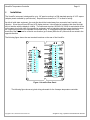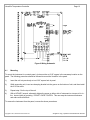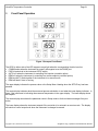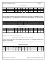
1
Versapro Temperature Controller Installation and Operation Handbook Revision 1.11 VersaPro Temperature Controller Page 2 Manual #: 022 Rev No: 1.11 Date: 30 October 2013 All trademarks used in this publication are duly marked and the sole property of their respective owners. No attempt at trademark or copyright infringement is intended or implied. COPYRIGHT No part of this publication may be reproduced, transmitted, transcribed, stored in a retrieval system, or translated into any language or computer language, in any form or by any means, electronic, mechanical, magnetic, optical, chemical, manual, or otherwise, without prior written permission of United Process Controls Inc. DISCLAIMER: The VersaPro is to be used by the industrial operator under his/her direction. United Process Controls Inc. is not responsible or liable for any product, process, damage or injury incurred while using the VersaPro. United Process Controls Inc. makes no representations or warranties with respect to the contents hereof and specifically disclaim any implied warranties or merchantability or fitness for any particular purpose. For assistance please contact: United Process Controls Inc. TEL: +1 513 772 1000 • FAX: +1 513 326 7090 Toll-Free North America +1-800-547-1055 [email protected] www.group-upc.com Copyright © 2013, United Process Controls Inc. All rights to copy, reproduce and transmit are reserved VersaPro Temperature Controller Page 3 TABLE OF CONTENTS TABLE OF CONTENTS ..................................................................................................................................................................... 3 1. Safety and Environment Information .................................................................................................................................... 7 1.1 Service and repair ........................................................................................................................................................................ 7 2. Installation Safety Requirements .......................................................................................................................................... 7 2.1 Safety Symbol .............................................................................................................................................................................. 7 2.2 Personnel ..................................................................................................................................................................................... 7 2.3 Enclosure of live parts .................................................................................................................................................................. 8 2.4 Live sensors .................................................................................................................................................................................. 8 2.5 Wiring .......................................................................................................................................................................................... 8 2.6 Power Isolation ............................................................................................................................................................................ 8 2.7 Earth leakage current .................................................................................................................................................................. 8 2.8 Over Current protection ............................................................................................................................................................... 8 2.9 Voltage rating .............................................................................................................................................................................. 9 2.10 Conductive pollution ............................................................................................................................................................... 9 2.11 Over‐temperature protection ................................................................................................................................................. 9 2.12 Grounding of the temperature sensor shield ........................................................................................................................ 10 2.13 Installation requirements for EMC ........................................................................................................................................ 10 2.14 Routing of wires .................................................................................................................................................................... 10 3 VersaPro Features .............................................................................................................................................................. 10 4 Installation ......................................................................................................................................................................... 11 4.1 Mounting ................................................................................................................................................................................... 12 5 Process Control Options ..................................................................................................................................................... 13 6 Control Modes ................................................................................................................................................................... 13 6.1 Time Proportioning (TP) ............................................................................................................................................................. 13 6.2 Time Proportioning Dual (TD) .................................................................................................................................................... 14 6.3 Time Proportioning with Complement (TC) ............................................................................................................................... 14 6.4 Position Proportioning (PP) ....................................................................................................................................................... 14 6.5 ON/OFF (OF) ............................................................................................................................................................................. 14 6.6 ON/OFF Dual (OD) ..................................................................................................................................................................... 15 6.7 ON/OFF with Complement (OC) ................................................................................................................................................ 15 6.8 Direct Current Output ................................................................................................................................................................ 15 6.9 Direct or Reverse Control Action ................................................................................................................................................ 16 7 Alarms ............................................................................................................................................................................... 16 Copyright © 2013, United Process Controls Inc. All rights to copy, reproduce and transmit are reserved VersaPro Temperature Controller Page 4 7.1 Process Alarms ........................................................................................................................................................................... 17 OFF ................................................................................................................................................................................................. 17 Full Scale HI .................................................................................................................................................................................... 17 Full Scale LO .................................................................................................................................................................................... 17 Deviation Band ............................................................................................................................................................................... 17 Deviation High ................................................................................................................................................................................ 17 Deviation Low ................................................................................................................................................................................. 17 Output High .................................................................................................................................................................................... 17 Output Low ..................................................................................................................................................................................... 18 Fault ................................................................................................................................................................................................ 18 Time ................................................................................................................................................................................................ 18 Start ................................................................................................................................................................................................ 18 Soak ................................................................................................................................................................................................ 18 7.2 Alarm Action .............................................................................................................................................................................. 18 7.3 Alarm Delay Times ..................................................................................................................................................................... 19 7.4 Diagnostic Alarms ...................................................................................................................................................................... 19 8 Serial Interface ................................................................................................................................................................... 20 9 Front Panel Operation ........................................................................................................................................................ 21 9.1 Enter Key .................................................................................................................................................................................... 22 9.2 Remote Key ................................................................................................................................................................................ 22 9.3 Setup Key ................................................................................................................................................................................... 22 9.4 Dual Key Functions .................................................................................................................................................................... 31 Starting Probe Tests ....................................................................................................................................................................... 31 Start Timer ...................................................................................................................................................................................... 31 Edit Timer ....................................................................................................................................................................................... 31 Monitor Mode ................................................................................................................................................................................ 31 10 Digital Input Event .............................................................................................................................................................. 32 OFF ................................................................................................................................................................................................. 32 PROB ............................................................................................................................................................................................... 32 AUTO (controller only) .................................................................................................................................................................... 32 rEn (controller only) ....................................................................................................................................................................... 32 ACK ................................................................................................................................................................................................. 32 PrOC (controller only) ..................................................................................................................................................................... 32 Strt (controller only) ....................................................................................................................................................................... 33 HOLd (controller only) .................................................................................................................................................................... 33 End (controller only) ....................................................................................................................................................................... 33 11 Timer Function ................................................................................................................................................................... 34 11.1 Setting the Timer .................................................................................................................................................................. 34 11.2 Time ...................................................................................................................................................................................... 35 11.3 Guaranteed Start Timer ........................................................................................................................................................ 35 11.4 Guaranteed Soak Timer ........................................................................................................................................................ 36 11.5 Timer Alarm Behavior ........................................................................................................................................................... 36 11.6 Timer State Diagram ............................................................................................................................................................. 36 12 Timer SIO Operations ......................................................................................................................................................... 38 Copyright © 2013, United Process Controls Inc. All rights to copy, reproduce and transmit are reserved VersaPro Temperature Controller 12.1 13 Controlling the Timer Remotely ............................................................................................................................................ 39 Tuning ................................................................................................................................................................................ 40 13.1 14 Page 5 What is tuning? ..................................................................................................................................................................... 40 Scaling Analog Inputs ......................................................................................................................................................... 43 14.1 Linear Example ...................................................................................................................................................................... 43 14.2 Keyboard Function during Input Slope .................................................................................................................................. 43 15 Scaling Analog Outputs ....................................................................................................................................................... 44 16 Calibration ......................................................................................................................................................................... 44 16.1 Calibration Displays and Keyboard Operation ...................................................................................................................... 45 16.2 Preparing for Input Calibration ............................................................................................................................................. 45 Calibration of the Thermocouple Input .......................................................................................................................................... 46 Calibration of the Cold Junction Temperature ............................................................................................................................... 46 Calibration of the Analog Output Channels ................................................................................................................................... 47 17 Communications ................................................................................................................................................................ 48 17.1 Modbus ................................................................................................................................................................................. 48 RTU Framing ................................................................................................................................................................................... 48 Address Field .................................................................................................................................................................................. 48 Function Field ................................................................................................................................................................................. 48 Data Field ....................................................................................................................................................................................... 49 Error Check Field (CRC) ................................................................................................................................................................... 49 17.2 MSI Message Protocol .......................................................................................................................................................... 50 17.3 Instrument Type ‘U’ Command Set ....................................................................................................................................... 52 ‘X’ Command .................................................................................................................................................................................. 52 Block Commands ............................................................................................................................................................................ 54 MSI Error Codes .............................................................................................................................................................................. 56 18 Troubleshooting Questions ................................................................................................................................................ 57 18.1 Analog Inputs ........................................................................................................................................................................ 57 18.2 Control Outputs..................................................................................................................................................................... 57 18.3 Digital Communications ........................................................................................................................................................ 58 18.4 Display Functions .................................................................................................................................................................. 58 18.5 Timer Function ...................................................................................................................................................................... 58 19 Versapro Monitor Mode ..................................................................................................................................................... 59 19.1 Prepare for Connection ......................................................................................................................................................... 59 19.2 How to Connect ..................................................................................................................................................................... 59 19.3 Start Monitor Mode .............................................................................................................................................................. 60 19.4 ‘D’ Display Command ............................................................................................................................................................ 61 19.5 ‘L’ Write FLASH to RAM Defaults .......................................................................................................................................... 61 19.6 ‘K’ Write RAM to EEPROM .................................................................................................................................................... 61 Copyright © 2013, United Process Controls Inc. All rights to copy, reproduce and transmit are reserved VersaPro Temperature Controller Page 6 19.7 ‘J’ Display EEPROM Values .................................................................................................................................................... 62 19.8 ‘S’ Status Display ................................................................................................................................................................... 62 19.9 ‘W’ Write RAM with EEPROM or Data Values ...................................................................................................................... 62 19.10 ‘X’ Exit Command .................................................................................................................................................................. 62 19.11 Viewing Status and Memory ................................................................................................................................................. 62 19.12 Loading Default Values ......................................................................................................................................................... 63 19.13 What if an error occurs ......................................................................................................................................................... 64 20 Technical Specification ....................................................................................................................................................... 65 20.1 Environmental ratings .......................................................................................................................................................... 65 20.2 Equipment ratings ................................................................................................................................................................. 65 20.3 General.................................................................................................................................................................................. 65 20.4 Electrical safety (pending approval) ..................................................................................................................................... 66 21 Versapro Memory Map ...................................................................................................................................................... 68 Copyright © 2013, United Process Controls Inc. All rights to copy, reproduce and transmit are reserved VersaPro Temperature Controller 1. Page 7 Safety and Environment Information Please read this section carefully before installing the controller This instrument is intended for industrial applications used in conjunction with Marathon Monitors zirconia oxygen sensors and standard thermocouple types. It is assumed that any installation meets either CE standards for industrial safety or NEC standard wiring practices. Failure to observe these standards or the installation instructions in this manual may degrade the safety or electrical noise protection provided by this instrument. It is the installer’s responsibility to ensure the safety and electrical noise compatibility of any installation. 1.1 Service and repair This controller has user replaceable fuses but no other user serviceable parts. Contact your Marathon Monitors Service (800-547-1055) for repair. Caution: Charged capacitors Before removing an instrument from its case, disconnect the supply and wait at least two minutes to allow capacitors to discharge. Failure to observe this precaution will expose capacitors that may be charged with hazardous voltages. In any case, avoid touching the exposed electronics of an instrument when withdrawing it from the case. Electrostatic Discharge (ESD) Precautions When the controller is removed from its case, some of the exposed electronic components are vulnerable to damage by electrostatic discharge. Anyone who is not probably ground using an ESD wrist strap or in contact with a ground while handling the controller may damage exposed electronic components. 2. Installation Safety Requirements 2.1 Safety Symbol Various symbols are used on the instrument, they have the following meaning: ! Caution, (refer to the accompanying documents) Functional earth (ground) terminal The functional earth connection is required for safety ground add to ground RFI filters. 2.2 Personnel Installation must be carried out by qualified personnel. Copyright © 2013, United Process Controls Inc. All rights to copy, reproduce and transmit are reserved VersaPro Temperature Controller 2.3 Page 8 Enclosure of live parts To prevent hands or metal tools touching parts that may be electrically live, the controller should be installed in an enclosure. The contacts on the rear of the instrument case or finger save but it is still possible for loose wiring, or metal objects to come in contact with live terminal connections. It is recommended that power be removed from the instrument connections before they are disconnected. However, instrument’s power connector can be removed with power applied. Care should be taken that the connector does not come in contact with any grounded object. 2.4 Live sensors The dc inputs, dc logic, and dc outputs are all electrically isolated from chassis ground. If the temperature sensor is connected directly to an electrical heating element then the inputs will also be live. The controller is designed to operate under these conditions. However you must ensure that this will not damage other equipment connected to these inputs and that service personnel do not touch connections to these terminals while they are live. With a live sensor, all cables, connectors and switches for connecting the sensor and nonisolated inputs and outputs must be mains rated. 2.5 Wiring It is important to connect the controller in accordance with the wiring data given in this handbook. Take particular care not to connect AC supplies to the low voltage sensor input or other low level inputs and outputs. Only use copper conductors for connections (except thermocouple inputs) and ensure that the wiring for installations comply with all local wiring regulations. For example, in the UK, use the latest version of the wiring regulations, BS7671. In the USA use NEC Class 1 wiring methods. 2.6 Power Isolation The installation must include a power isolating switch or circuit breaker. This device should be in close proximity to the control actuator, and within easy reach of the operator. There is no means of disconnecting power from the instrument other than removing the connectors from the rear of the instrument. It is recommended that additional power disconnects are provided in the installation to remove power from these connectors as well. 2.7 Earth leakage current Due to RFI Filtering there is an earth leakage current of less than 0.5mA. This may affect the design of an installation of multiple controllers protected by Residual Current Device, (RCD) or Ground Fault Detector, (GFD) type circuit breakers. 2.8 Over Current protection The instrument has an internal 3.15 Amp fuse (P/N MFU-3.15PCTT) for instrument power and 1 Amp fuses (P/N MFU-1.0PCTT) for the control contacts and alarms. It is recommended that additional protection against excess currents be used for loads exceeding this rating. Fusing and interposing relays should be added to the control circuit if high current or large inductive loads are used. Copyright © 2013, United Process Controls Inc. All rights to copy, reproduce and transmit are reserved VersaPro Temperature Controller 2.9 Page 9 Voltage rating The maximum continuous voltage applied between any of the following terminals must not exceed 250VAC: line or neutral to any other connection; relay output to logic, dc or sensor connections; any connection to ground. The controller should not be wired to a three phase supply with an unearthed star connection. Under fault conditions in this supply could rise above 264VAC with respect to ground and the product would not be safe. Voltage transients across the power supply connections, and between the power supply and ground, must not exceed 2.5kV. Where occasional voltage transients over 2.5kV are expected or measured, the power installation to both the instrument supply and load circuits should include a transient limiting device. These units will typically include gas discharge tubes, metal oxide varistors, and constant voltage transformers help suppress voltage transients on the supply line due to lightning strikes or inductive load switching. Devices are available in a range of energy ratings and should be selected to suit conditions at the installation. 2.10 Conductive pollution Electrically conductive pollution must be excluded from the cabinet in which the controller is mounted. For example, carbon dust is a form of electrically conductive pollution. To secure a suitable atmosphere in conditions of conductive pollution, fit an air filter to the air intake of the cabinet. Where condensation is likely, for example at low temperatures, include a thermostatically controlled heater in the cabinet. 2.11 Over-temperature protection When designing any control system it is essential to consider what will happen if any part of the system should fail. In temperature control applications the primary danger is that the heating will remain constantly on. Apart from scrapping the product, this could damage any process machinery being controlled or even cause a fire. Reasons why the heating might remain constantly on include: the temperature sensor becoming detached from the process; thermocouple wiring becoming a short circuit; the controller failing with its heating output constantly on; an external valve or contactor sticking in the heating condition; the controller setpoint set too high. Where damage or injury is possible, we recommend fitting a separate over-temperature protection unit. Factory Mutual requires that any over temperature device use an independent temperature sensor, which will isolate the heating circuit. Please note that the alarm relays within the controller will not give protection under all failure conditions. This instrument is not suited for over temperature protection and should not be used as a safety device. Copyright © 2013, United Process Controls Inc. All rights to copy, reproduce and transmit are reserved VersaPro Temperature Controller 2.12 Page 10 Grounding of the temperature sensor shield In some installations it is common practice to replace the temperature sensor while the controller is still powered up. Under these conditions, as additional protection against electric shock, we recommend that the shield of the temperature sensor be grounded at one end of the wire. Do not rely on grounding through the framework of the machine. 2.13 Installation requirements for EMC To ensure compliance with European EMC directives certain installation precautions are necessary as follows: When using relay outputs it may be necessary to fit a filter suitable for suppressing the emissions. The filter requirements will depend on the type of load. For typical applications such as Schaffner FN321 or FN612 line filters or equivalents. If the unit is used in table top equipment which is plugged into a standard power socket, it is likely that compliance to the commercial and light industrial emissions standard is required. In this case, to meet the conducted emissions requirement, a suitable mains filter should be installed. Recommended filters would be Schaffner types FN321 and FN612 or equivalents. 2.14 Routing of wires To minimize the pick-up of electrical noise, the wiring for low voltage dc and particularly the sensor input should be routed away from high-current power cables. Where it is impractical to do this, use shielded cables with the shield grounded at one end. 3 VersaPro Features The VersaPro is a single loop process controller / monitor has the following capabilities: 24 bit Sigma-Delta ADC for thermocouple with cold junction compensation. Two (2) 4-20 milliamp outputs for control or chart recorder. Sixteen character LCD with two four-digit LED segment displays. Two (2) Form A control contacts. (controller) Two (2) Form A alarm contacts. PID control modes. (controller) Serial Communication with Marathon Monitors or Modbus Protocol. EEPROM stores setup and calibration values. Copyright © 2013, United Process Controls Inc. All rights to copy, reproduce and transmit are reserved VersaPro Temperature Controller 4 Page 11 Installation The VersaPro instrument is designed for up to 1/8" panel mounting in a DIN standard opening of 3.62" square (adapter panels available by special order). Required rear clearance is 7.5” to allow for wiring. As with all solid state equipment, the controller should be located away from excessive heat, humidity, and vibration. Since the unit uses LED and LCD display devices, it should also be located so that direct sunlight will not interfere with the display's visibility. The instrument requires 120/240 VAC 50/60 Hz and should not be on the same circuit with other noise-producing equipment such as induction machines, large electrical motors, etc. Signal wiring must be run separate from control wiring. It is suggested that signal wiring at the rear terminals of the instrument be routed in one direction (up or down) while the AC power wires are routed in the opposite direction. The following figure shows the rear terminals locations on the rear of the VersaPro. Figure 1 VersaPro Rear Panel The following figure shows a typical wiring schematic for the Versapro temperature controller. Copyright © 2013, United Process Controls Inc. All rights to copy, reproduce and transmit are reserved VersaPro Temperature Controller Page 12 Figure 2 Wiring Schematic 4.1 Mounting To mount the instrument in a control panel, a hole must be cut 3.62" square in the necessary location on the panel. The following procedure should be followed to mount the VersaPro in the panel. 1) Insert the unit into previously cut out 3.62" square hole in panel. 2) While supporting unit, insert one clamping bracket into the groove on the bottom of unit, and then install the 6-32 set screw. 3) Repeat step 2 for the top of the unit. 4) With a HEX KEY wrench, alternately tighten the screw on either side of instrument to a torque of six in.lbs. Insure rigidity of mounting. DO NOT OVER TIGHTEN. This can wrap the instrument enclosure and make removal difficult. To remove the instrument from the panel, reverse the above procedures. Copyright © 2013, United Process Controls Inc. All rights to copy, reproduce and transmit are reserved VersaPro Temperature Controller 5 Page 13 Process Control Options The Versapro is configured to perform as a single loop PID controller for a specific process. This instrument is setup as an oxygen controller. Table 1 Instrument Control Options Function Temperature Linear Input A Linear Input B 6 Description Uses the temperature signals from a thermocouple to control to temperature setpoint. Uses the millivolt signal from a linear sensor connected to terminals +TC / -TC Uses the millivolt signal from a linear sensor connected to terminals +MV / -MV Control Modes The VersaPro controller provides: Time Proportional Single (TP) Time Proportional Dual (TD) Time Proportional Compliment (TC) Position Proportioning (PP) On/Off (OF) On/Off Dual (OD) On/Off Compliment (OC) Direct Signal Output (4-20mA) The instrument controls with two control contacts or direct 4-20mA output from two analog output channels. The control function can be set to direct acting or reverse acting. Direct acting increases the output control signal to increase the process. Reverse acting decreases the output control signal to increase the process. 6.1 Time Proportioning (TP) Time proportioning adjusts the duty cycle of the control device to maintain control. This is usually done with solenoid valves controlling the flow of a trim gas or addition air to the process. The control loop percent output is the percentage of the ON time relative to total cycle time. The cycle time is the ON time plus OFF time. For example if the control loop percent output is 34% and the cycle time is 10 seconds, then the ON time would be 3.4 seconds and the OFF time would be 6.6 seconds. The selection of the proper cycle time is a tradeoff between excess wear and tear on the solenoid valve with short cycle times or oscillation of the control process using long cycle times. Only the first control contact is used in this mode. Copyright © 2013, United Process Controls Inc. All rights to copy, reproduce and transmit are reserved VersaPro Temperature Controller 6.2 Page 14 Time Proportioning Dual (TD) This mode is used when there are two processes to control that have complementary effects; like heat and cool. The time proportioning dual mode uses two control outputs; one for heat and one for cool. There is never a time when both outputs are on simultaneously. The control loop computes a percent output from -100 to +100%. When positive, the proportioning action applies to the forward output. When negative the proportioning action applies to the reverse output. 6.3 Time Proportioning with Complement (TC) This mode is identical to the time proportioning mode except that both control outputs are used. The second control output is the complement of the first. That is when the first output is ON then the second is OFF and vice versa. This mode is used with single action motorized valves that open quickly when a voltage is applied to one terminal and close quickly when voltage is applied to the other terminal. 6.4 Position Proportioning (PP) This mode is used with motorized valves that do not have slidewire feedback. This mode is sometimes referred to as "bump" mode because it "bumps" the valve slightly more open or closed. This mode uses both control outputs; one to drive the motor forward (open) and the other to drive it reverse (closed). The control output is the difference between the new percent output and the last percent output. If the difference is positive than the valve motor is driven open for that percentage of the cycle. If negative it is driven closed by that percentage of the cycle time. For example if the new percent out is 60% and the old was 45% then the motor is driven open for 15% of the cycle time. If the cycle time is set to the time that the motor takes to move from fully closed to fully open, then the flow is theoretically increased by 15%. Two special cases exist. If the control output is computed at 100% then the motor is driven continuously in the open direction. Likewise if the control output is computed as 0% then the motor is driven continuously closed. There is a built in deadband for this control based on the length of the cycle time. The comparison between the previous and current output values are made at the end of each cycle time. Faster comparisons can be made by shortening the cycle time assuming that a 100% command output is a continuously close control contact. 6.5 ON/OFF (OF) ON/OFF control is exactly what it implies, the control action is either ON or OFF. With true ON/OFF control the control output is ON whenever the process is below the setpoint value and OFF when the process is at or above the process value. In many real world applications this simple control method will cause "contact chatter" because of noisy signals which will switch the ON and OFF states rapidly. Also since the control action does not turn OFF until the setpoint is reached, the process will overshoot due to lags in the control action. Marathon controllers incorporate two features that prevent these problems from occurring; hysteresis and deadband. Hysteresis provides a delay between the control on point and the off point. Noise will not cause the control output to “chatter” with this gap applied. Hysteresis is ±20% of the deadband value. Copyright © 2013, United Process Controls Inc. All rights to copy, reproduce and transmit are reserved VersaPro Temperature Controller Page 15 Deadband allows the process to deviate away from the setpoint by the width of the deadband before any control action occurs. The deadband is adjusted through the Proportional Band in units of the displayed setpoint value. The reset and rate values have no effect in ON/OFF control. Let’s assume the process setpoint is 1500° with a proportional band of 5. This represents a deadband of 5°, which is a band of ±5° around setpoint. The hysteresis is 1° of the setpoint or 20% of the deadband. The output is turned on when the process drops below 1495° and turns off then it reaches 1499°. The deadband controls the point where the control is turned on to correct any deviation from setpoint. The hysteresis controls the point where the control is turned off to prevent overshoot or chatter. 6.6 ON/OFF Dual (OD) This mode is similar to the time proportioning dual mode. The forward output acts as described in the ON/OFF description above. The reverse output responds when the process is above the setpoint. Using the temperature example with a proportional band (deadband) of 5, the heat contact would turn on when the process is 1495° and will turn off when it comes to 1499°. Likewise the cool contact would turn on when the process exceeds 1505° and will turn off when it drops to 1501°. 6.7 ON/OFF with Complement (OC) This mode is exactly like ON/OFF control with the addition of a second control output. The second control contact is turned ON when the first is control contact is OFF and vice versa. 6.8 Direct Current Output The Versapro has two analog output channels that provide an isolated 4 to 20mA signal proportional to selectable process values. The analog outputs can be configured to control the process by driving actuators with a 4-20mA signal proportional to the calculated percent output of the PID loop. One or both output channels can be used depending on the control mode selected. POUT selection drives the output signal based on the HIPO and LOPO settings. If a Dual Time Proportioning control mode is selected with a HIPO = 100 and a LOPO = -100 then the output will be 4mA for –100%, 12mA for 0%, and 20mA for +100% output. This setting is helpful if one actuator is driving two valves in a split configuration where air is fully opened at – 100% and gas is fully opened at +100% or both are closed at 0%. It is possible to drive two actuators independently by setting on output to PO1 or PO2 where PO1 is the 0 to +100% control output and PO2 is 0 to –100%. In this configuration both outputs are at the maximum (±100%) with an output of 20mA. It is also possible to drive one actuator with an output channel and a solenoid with a control contact. For example, select PO1 for one analog output channel to drive a gas actuator and connect an air solenoid to the reverse control contact. The percent output for both functions is determined by the PID settings. The cycle time should be set to the stroke time required to fully open the actuator from a fully closed condition. Typical stroke times would be 30 to 45 seconds. The control contacts will still act as described in the previous modes even if the analog output channels are being used. Copyright © 2013, United Process Controls Inc. All rights to copy, reproduce and transmit are reserved VersaPro Temperature Controller 6.9 Page 16 Direct or Reverse Control Action Control action determines how the output of the controller will react to effect a change on the process. The control action is considered ‘direct’ if an increase in the output produces an increase in the process value. A ‘reverse’ control action would be when an increase in the output produces a decrease in the process. For example oxygen would require a reverse acting control if the process component the instrument is controlling is a trim gas. Increasing the trim gas will result in a decrease in the oxygen reading. It is considered a direct acting control if the process component under control is additional air. Either process would use the first control contact; it would just be activated above or below the process setpoint depending on what is being added to the process. 7 Alarms The instrument has two types of alarms, process alarms and diagnostic alarms. If an alarm has been selected and conditions are such that the alarm becomes active, the instrument will display this condition on the center LCD display. The alarms a numbered as Alarm 1 and Alarm 2. The various displays for active alarm conditions would be displayed as shown below. N indicates the position of the alarm number, 1 or 2. ALARM DISPLAY PROCESS HIGH CONDITION Process alarm, contact assignable PROCESS LOW Process alarm, contact assignable PROCESS HIGH OR LOW Process alarm, contact assignable PROCESS HIGH Process alarm, contact assignable PROCESS LOW Process alarm, contact assignable PROCESS HIGH Process alarm, contact assignable PROCESS LOW Process alarm, contact assignable TIMER END Alarm contact assigned to TinE, Strt, SOAK LLLL Display only HHHH Display only FLASH CSUM Fault alarm, contact assignable EEPROM CSUM Fault alarm, contact assignable KEYBOARD Fault alarm, contact assignable Copyright © 2013, United Process Controls Inc. ACTION Full Scale High, Contact automatically resets unless latched. Full Scale Low, Contact automatically resets unless latched. Deviation Band, Contact automatically resets unless latched. Deviation High, Contact automatically resets unless latched. Deviation Low, Contact automatically resets unless latched. Power Output High, Contact automatically resets unless latched. Power Output Low, Contact automatically resets unless latched. Timer end alarm when the timer counts to zero for Timer, Start, or Soak timer modes. The contact latches until reset by pressing the Enter key or through the Input Event. Displays process value within display range or exponent setting Displays process value within display range or exponent setting Reset instrument power. Return to Marathon if error does not clear. Reset instrument power. Return to Marathon if error does not clear. Reset instrument power. Do not push any keys while instrument is powered on. Return to Marathon if error does All rights to copy, reproduce and transmit are reserved VersaPro Temperature Controller Page 17 ALARM DISPLAY CONDITION FLASH ERASE Fault alarm, contact assignable FLASH / EE SIZE Fault alarm, contact assignable TEMP OPEN Fault alarm, contact assignable ACTION not clear. Programming error, Reset instrument power, attempt reload. Programming error, Reset instrument power, attempt reload. Check thermocouple for open condition or loose connection. 7.1 Process Alarms The process alarms can be setup to activate either or both of the two alarm contacts provide on the VersaPro. Nine user selectable modes are available. The Full Scale HI, Full Scale LO, Fault, and Probe alarms are available in the monitor. Of the alarms listed are available in the controller. OFF Disables the alarm function and the alarm contacts Full Scale HI An alarm is generated any time the process value goes above the Full Scale HI alarm value. This alarm is reset if the process falls below the alarm value or acknowledgement from the front panel or through the event input (if configured). Full Scale LO An alarm is generated any time the process value drops below the Full Scale LO alarm value. The alarm will arm once the process is measured above the alarm value. This alarm is reset with an acknowledgement from the front panel or through the event input (if configured). Deviation Band An alarm is generated any time the process value goes above or below the band alarm setting. The alarm setting is value of the band. For example, if a value of 10 is entered as the alarm value, an alarm is generated if the process goes 10 units above or 10 units below the setpoint. Units are the process units such percent or degrees. This alarm will not arm until the process is in-band of the setpoint. Deviation High An alarm is generated any time the process value goes above the band alarm setting. The alarm setting is number of units allowed above setpoint. Units are the process units such percent or degrees. This alarm will not arm until the process is in-band of the setpoint. Deviation Low An alarm is generated any time the process value goes below the band alarm setting. The alarm setting is number of units allowed below the setpoint. Units are the process units such percent oxygen or degrees. This alarm will not arm until the process is in-band of the setpoint. Output High An alarm is generated any time the control percent output exceeds the alarm value. The alarm setting is maximum percent output allowed. Copyright © 2013, United Process Controls Inc. All rights to copy, reproduce and transmit are reserved VersaPro Temperature Controller Page 18 Output Low An alarm is generated any time the control percent output drops below the alarm value. The alarm setting is minimum percent output allowed. Fault An alarm is generated any time an open input occurs on the T/C input. The input is pull up to a maximum value if no input is connected or if the input fails in an open circuit mode. The center display will indicate which of these conditions has caused the alarm. The alarm process will also become active if any of the listed hardware faults occur. The center display will indicate which of these conditions has caused the alarm. Time This alarm setting is necessary for the timer function to work. The timer will only run if it is enabled in the Ctrl Setup menu and a timer setpoint value other than zero has been assigned. This alarm setting allows the timer to start running when it is activated at the Start Timer parameter in the Setpt key menu, when the dual key combination Left Arrow and Enter keys are pressed, or if the Input Event has been configured for Start and a contact closure occurs. The timer will start running as soon as it starts, independent of any process values. See the Timer section for more details. Start This alarm setting is necessary for the timer function to work. The timer will only run if it is enabled in the Ctrl Setup menu and a timer setpoint value other than zero has been assigned. This alarm setting allows the timer to be activated from the Start Timer parameter in the Setpt key menu, when the dual key combination Left Arrow and Enter keys are pressed, or if the Input Event has been configured for Start and a contact closure occurs. The timer will start running as soon as the process level is above the alarm value and will continue to run once it has started. See the Timer section for more details. Soak This alarm setting is necessary for the timer function to work. The timer will only run if it is enabled in the Ctrl Setup menu and a timer setpoint value other than zero has been assigned. This alarm setting allows the timer to be activated from the Start Timer parameter in the Setpt key menu, when the dual key combination Left Arrow and Enter keys are pressed, or if the Input Event has been configured for Start and a contact closure occurs. The timer will start running as soon as the process level is within the band around setpoint determined by the alarm value. The timer will stop any time the process falls outside the band limit. See the Timer section for more details. 7.2 Alarm Action Each alarm can be configured to operate in several different modes. Each alarm can be configured as a reverse (normally closed) contact. This mode is usually used for failsafe alarms that will open during an alarm condition, fault, or power failure. Each alarm can also be configured as a direct (normally open) contact that closes when an alarm condition occurs. In both cases the alarm will automatically clear if the alarm condition is resolved. Each alarm can also be configured for either reverse or direct latched conditions. In this mode the alarm contact will remain active until an acknowledgement is received through the event port or by pressing the ENTER key. Copyright © 2013, United Process Controls Inc. All rights to copy, reproduce and transmit are reserved VersaPro Temperature Controller 7.3 Page 19 Alarm Delay Times Each alarm can have delay ON, delay OFF, or both delays applied. Delays can be applied in increments of a second, up to a maximum of 250 seconds. ON delays are helpful if a known upset in the process can be ignored. This avoids nuisance alarms but still maintains an active alarm if the alarm condition persists following the delay. OFF delays will hold the alarm contact active for a determined period of time once the alarm condition has cleared. This can be helpful as an interlock to other process functions that may have to recover following an alarm condition. 7.4 Diagnostic Alarms A diagnostic alarm is shown on the instrument’s center display when a fault is detected in the internal hardware during power up. These alarms included: FLASH CSUM EEPROM CSUM KEYBOARD FLASH ERASE FLASH / EE SIZE A fault has been detected in the Flash memory. A fault has been detected in the EEPROM. A key is stuck or was held down during power up. This error may occur during instrument programming. The Flash memory may be faulty. Retry programming; make sure the communications link to the instrument is working properly. This error may occur during instrument programming. The Flash memory may be faulty. Retry programming; make sure the communications link to the instrument is working properly. If either alarm contact is configured for a fault this alarm will engage if any of the above faults occur. The LCD display will indicate the fault condition. The front panel display will show 0000 if the process value is below the display resolution, or HHHH if the process value is above the display resolution. It may be necessary to adjust the oxygen exponent and/or the oxygen decimal point settings if these symbols occur. Copyright © 2013, United Process Controls Inc. All rights to copy, reproduce and transmit are reserved VersaPro Temperature Controller 8 Page 20 Serial Interface The VersaPro has a single RS-485 half duplex (two wire) communications port. This port can be configured for either the Marathon protocol of Modbus RTU protocol. Baud rates and parities are selectable. The Modbus protocol only uses a parity of none. See the section on communications for details on both of these protocols. The Versapro can be connected to networks with up to 128 similar devices. The differential transceiver used in the Versapro meets or exceeds the TIA/EIA-485 and ISO/IEC 8482:1993(E) standards. Connections for the serial interface should be connected to the following terminals: TB-B 13 TB-B 14 RTX + RTX – All connections to any RS-485 bus should be made with shielded twisted pair wires using a low capacitance cable specified for RS-485 multi-drop connections. The shield should be connected to ground on one end of the wire run. Shield continuity should be maintained between wire segments. Each end of the network should be terminated with a resistor that is close to the impedance of the cable. 100 to 120 ohms are typical values. All connections to multiple instruments should be made in a daisy-chain fashion, from one instrument to the next. A star network connection should never be used. A repeater should be considered for cable distances beyond 3900 feet (1.2Km). Any network that is run between buildings should use repeaters with optical fiber connections between buildings to avoid any noise spikes generated by lightning strikes. Copyright © 2013, United Process Controls Inc. All rights to copy, reproduce and transmit are reserved VersaPro Temperature Controller 9 Page 21 Front Panel Operation Figure 3 Versapro Front Panel The LEDS to either side of the LED segment arrays light when the corresponding function is active. COMM flashes when the instrument is properly interrogated over the RS485 port. PWR is hard wired to the instrument 5VDC supply AUTO is lit when the instrument is controlling to a setpoint (controller option) REM is lit when the instrument is controlling to a remote setpoint (controller option) REM and AUTO flash together if the instrument is in manual mode. REM will flash if timer is running. The upper display indicates the process value or the Setup Menu Heading when the SETUP key has been pressed. The center display indicates what the measured process calculation is and what the lower display indicates. In figure 3 the instrument is indicating the measured temperature in the upper display. The lower display shows the setpoint. The center display also shows the parameter name in Setup mode or fault and alarm messages if any are active. The lower display shows the instrument setpoint if the controller is in automatic or remote mode. The display will switch to control output level when the instrument is changed to manual. Copyright © 2013, United Process Controls Inc. All rights to copy, reproduce and transmit are reserved VersaPro Temperature Controller 9.1 Page 22 Enter Key If the normal process display is showing on the LED and LCD displays, then pressing the Enter key will cycle the LCD and lower LED through various controller parameters. For the controller, the display will cycle through the following list, the monitor will show only a partial list. TEMP / SETPT TEMP / %OUT REMAINING TIME The temperature process value will always be displayed in the top LED display. Each time an alarm occurs the particular alarm prompt will appear in the LCD display. The process information will continue to display normally if the Enter key is pressed. It is still possible to view any active alarm by pressing the UP or DOWN arrow keys. 9.2 Remote Key Pressing the REM key causes the VersaPro to cycle between Remote, Automatic, or Manual control. This key has no function in the monitor version. When switching from Automatic to Manual or Manual to Automatic, the control output remains at the last output value in either mode. This allows for a bumpless control transition between manual and automatic mode. When the controller is set to Automatic mode the “Auto” LED lights and the lower display indicates the process setpoint (default). When the controller is set to Remote mode the “Rem” LED lights and the VersaPro will accept a remote setpoint from a master on the host serial interface. The lower display indicates the process setpoint (default). The Setpt key does not work if the instrument is in remote mode. When the controller is set to Manual mode both the “Rem” and “Auto” LED’s will flash together and the lower display indicates the power output of the controller. This value can be manually increased or decreased in 1% steps by pressing the UP or DOWN arrow keys. Pressing the RIGHT or LEFT arrow keys changes the output in 10% steps. The output will remain in the last control level if the instrument is switched into manual mode from remote or automatic or back to either setpoint control mode. 9.3 Setup Key The instrument can be placed in setup mode by pressing and holding the SETUP key for 5 seconds. The upper display initially shows the first setup menu while the center and lower displays are blank. At this level you can select different menus by pressing the RIGHT or LEFT arrow keys. The upper display will change accordingly. You can enter a menu by pressing the ENTER key when the desired menu heading is being displayed. Pressing the arrow keys can change menu parameters. Value changes can be saved or the next parameter can be selected by pressing the ENTER key. The menu parameters will continue to cycle through the display Copyright © 2013, United Process Controls Inc. All rights to copy, reproduce and transmit are reserved VersaPro Temperature Controller Page 23 as long as the ENTER key is pressed. A new menu can be select only when the menu heading is displayed. You can exit from the Setup mode by pressing the SETUP key at any time. The following tables outline the Setup menus available in the VersaPro Controller and Monitor when the operator presses the SETUP key. Table 2 Setup Menus Setup Menu Heading CtrL Inpt CaLc Aout ALr HOST Info CaL Description Control functions and PID Thermocouple type and Millivolt setup Lower Display setting Analog output selection and parameters Alarm contact configurations Host Communication configuration General information displays Input / Output calibration You have to press the SETUP key for five seconds to activate the setup mode. Initially when the setup mode is activated, the LCD display will show the first menu heading, the upper and lower LED displays are blank. Page to the next Menu heading by pressing the RIGHT or LEFT arrow keys. The menu headings will continue to wrap around as the RIGHT or LEFT arrow keys are pressed. Pressing the SETUP key at any point while in the Setup Menus will return the display to the normal process display. See the following figure. Copyright © 2013, United Process Controls Inc. All rights to copy, reproduce and transmit are reserved VersaPro Temperature Controller Page 24 The displayed menu is selected by pressing the ENTER key. The first parameter name in the selected menu list will appear in the center display. The upper LED group continues to display the menu name, the center display shows the parameter name, and the lower LED group shows the parameter value. A flashing cursor in the lower LED display indicates which digit can change if the parameter value is numeric. The UP or DOWN arrows increase or decrease the digit value. The RIGHT or LEFT arrow keys move the cursor to the right or left digit. Figure 4 Control Menu Heading No left to right or right to left wrap-around is provided for the cursor. If the parameter has a table of choices such as thermocouple types, the various selections can be displayed by pressing the UP or DOWN arrows. No digit flashes in parameter displays that have a list of choices. In either case, the selection is set when the ENTER key is pressed and the display advances to the next parameter. In the example shown above, the selected menu is Control (CtrL), the selected parameter is PROCESS SOURCE, and the displayed parameter value is temperature (TEnP). This is one of several control types that are available. Different control selections can be made by pressing the UP or DOWN arrow keys. Pressing the SETUP key at any time escapes from the menu display and returns to the normal process display. You can only select another menu heading when the display is at a menu heading. The following figures and tables outline the menu options and parameters under the Setup key. Copyright © 2013, United Process Controls Inc. All rights to copy, reproduce and transmit are reserved Copyright © 2013, United Process Controls Inc. ENTER (HOLD FOR 5 SECONDS) SETUP TC OR MV BREAK TIMER ENABLE LOW PERCENT OUT HI PERCENT OUT CYCLE TIME RATE RESET PROPORTIONAL BAND DIGITAL EVENT MV FILTER ALARM 2 TIME OFF DELAY ALARM 2 TIME ON DELAY ALARM 2 ACTION FIRMWARE REVISION PERCENT OUTPUT COLD JUNCTION (DEG) MILLIVOLT PROB IN MILLIVOLT TEMP IN INFO PRESSING SETUP KEY ANYTIME ESCAPES FROM MENU. ALARM 2 TYPE ANALOG 2 RANGE TC FILTER IN B SLOPE DELAY ALARM 1 TIME OFF DELAY ANALOG 2 OFFSET F OR C ALARM 2 VALUE PARITY ALARM 1 TIME ON DELAY ANALOG 2 UNIT IN A SLOPE IN B OFFSET BAUD RATE ADDRESS ALARM 1 VALUE ANALOG 1 OFFSET ALARM 1 ACTION PROTOCOL HOST ALARM 1 TYPE ALR ANALOG 1 UNIT AOUT ANALOG 1 RANGE DISPLAY DECML PT CALC IN A OFFSET COLD JUNC APPLY CONTROL MODE CONTROL ACTION TC TYPE INPT PROCESS SOURCE CTRL OUTPUT 2 SPAN OUTPUT 2 MIN OUPUT 1 SPAN OUTPUT 1 MIN CAL OUTPUT CJ OFFSET TC SPAN TC ZERO CAL INPUT CAL VersaPro Temperature Controller Page 25 Figure 5 Setup Menu Tree All rights to copy, reproduce and transmit are reserved VersaPro Temperature Controller Page 26 Table 3 Control Menu (CtrL) Parameter Name PROCESS SOURCE Units or Options TEMP, INPUT A, INPUT B Range Display range: -500 to 9999 for temp 0 to 100 or EU for Input A 0 to 2000 or EU for Input B CONTROL MODE TP, TC, TD, PP, OF, OC, OD or NON CONTROL ACTION PROPORTIONAL BAND DIR/REV Process Value 0 – 9999 RESET Repeats / min 00.00 – 99.99 RATE Repeats / min 00.00 – 9.99 CYCLE TIME SECONDS 0 – 255 HI PERCENT OUT 0 – 100 LOW PERCENT OUT TC OR MV BREAK MAXIMUM OUTPUT MINIMUM OUTPUT ZERO / HOLD TIMER ENABLE YES / NO -100 to 100 Description Control type only available on instrument’s specific configuration. This selection controls what other parameters will be available. See Control Modes if configured as a controller, shows NON (MONITOR) only if the instrument is configured as a monitor. Direct or Reverse control action Proportional Band value in displayed process units for PID control or Deadband in ON/OFF control Integral control value, no effect in ON/OFF settings Derivative control value, no effect in ON/OFF settings Proportional time period (TP, TC, TD) Sets max. forward control. Output Sets min. reverse control output Sets output control to zero or holds current output if a TC or millivolt input open condition occurs. Input A only checks TC input, Input B only checks mV input. Enables timer function Table 4 Input Menu (InPt) Parameter Name TC TYPE Units or Options B, E, J, K, N, R, S, T COLD JUNC APPLY YES or NO IN A OFFSET Only in Linear mode Copyright © 2013, United Process Controls Inc. Range -999 – 9999 Description See Input calibration for thermocouple ranges. Linear mode allows for input scaling, see IN A OFFSET and IN A SLOPE. Applies the cold junction correction or not when a thermocouple type is selected. In LINEAR mode the cold junction is never applied. Default is NO. Linear offset to scale Input A to Engineering Units when INPUT A is selected as the process All rights to copy, reproduce and transmit are reserved VersaPro Temperature Controller Page 27 Parameter Name Units or Options Range IN A SLOPE Only in Linear mode -999 – 999 -99.9 – 99.9 -9.99 – 9.99 -.999 - .999 TEMP SCALE TC FILTER F OR C SECONDS IN B OFFSET Works only in mV Mode -999 – 9999 IN B SLOPE Works only in mV Mode -999 – 999 -99.9 – 99.9 -9.99 – 9.99 -.999 - .999 MV FILTER SECONDS 0 – 450 Description source. Linear slope to scale Input A to Engineering Units when INPUT A is selected as the process source. This is the slope number in the linear calculation where: EU = SLOPE(mV) + OFFSET See key Sets temperature scale. Temperature filter setting in seconds. Filters the temperature value with a moving average time window. Linear offset to scale Input B to Engineering Units when INPUT B is selected at the process source. This is the offset in used in the SLOPE(mV) + OFFSET equation. Linear slope to scale Input B to Engineering Units when INPUT B is selected as the process source. This is the slope number in the linear calculation where: EU = SLOPE(mV) + OFFSET Millivolt filter setting in seconds. Filters the millivolt reading with a moving average time window. 0 – 450 Table 5 Calculation Menu (CALC) Parameter Name DISPLAY DECML PT Units or Options Decimal point Range 0-4 Description Sets decimal pt., available for Input A and Input B. Table 6 Analog Output Menu (AOUt) Parameter Name ANALOG 1 UNIT ANALOG 1 OFFSET Units or Options LIN A, LINB B, TENP, POUT, PO1, PO2 , PROG Offset for selected process value or percent output. Range 4 to 20mA output. Description -30.0 to 300.0 for O2 and LIN This is the minimum value of the process associated with the 4mA output. The magnitude of this number is based on the display resolution. In POUT mode the offset is fixed to the LOPO value. When PROG is selected the offset is fixed at 0 -300 to 3000 for temperature LOPO for POUT Copyright © 2013, United Process Controls Inc. All rights to copy, reproduce and transmit are reserved VersaPro Temperature Controller Parameter Name ANALOG 1 RANGE Page 28 Units or Options Span scaling for selected process value or percent output. Range Description 0 or DAC_OFFSET for PROG 0 to 9999 for O2, LIN, and Temp HIPO for POUT 4096 or DAC_SPAN for PROG ANALOG 2 UNIT ANALOG 2 OFFSET ANALOG 2 RANGE LIN A, LINB B, TENP, POUT, PO1, PO2 , PROG Offset for selected process value or percent output. Span scaling for selected process value or percent output. This is the maximum value of the process associated with the 20mA output. The magnitude of this number is based on the display resolution.When POUT is selected this value is fixed to the HIPO value. When PROG is selected the range is fixed at 4096 Same as Analog 1 Same as Analog 1 Same as Analog 1 Table 7 Alarm Menu (ALr) Parameter Name ALARM 1 TYPE Units or Options OFF FSHI, FSLO dUbd dbHI dbLO HIPO LOPO FALt PROB tinE Strt SOAk Range Description OFF disables alarm contact. FSHI - Full Scale HI, active when process is above ALARM 1 VALUE. FSLO - Full Scale LO, active when process is below ALARM 1 VALUE. dUbd – Deviation Band available for the controller only, active when process is outside of symmetrical band around setpoint. dbHI – Deviation High, defines a process band above the process setpoint. The alarm is active if the process moves outside this band. dbLO – Deviation Low, defines a process band below the process setpoint. The alarm is active if the process moves outside this band. Copyright © 2013, United Process Controls Inc. All rights to copy, reproduce and transmit are reserved VersaPro Temperature Controller Parameter Name Page 29 Units or Options Range Description HIPO – Output High, this alarm sets the threshold for the maximum control output allowed which is set by ALARM 1 VALUE. ALARM 1 VALUE ALARM 1 ACTION ALRM 1 TM ON DLY ALRM 1 TMOFF DLY ALARM 2 TYPE ALARM 2 VALUE ALARM 2 ACTION ALRM 2 TM ON DLY ALRM 2 TMOFF DLY LOPO – Output Low, this alarm sets the threshold for the minimum control output allowed which is set by ALARM 1 VALUE. FALt – Fault, open inputs for mV, thermocouple or hardware fault. Prob – Probe, fault active if impedance or verification are out of range. tinE – Time, establishes alarm contact as the contact used for the End alarm. Strt – Start, same as Time. SOAk – Soak, same as Time. Trigger setpoint value REV = Reverse (N.C.) can be acknowledged even if the condition still exists. LREV = Latched Reverse (N.C.) can not be acknowledged if the condition still exists. DIR = Direct (N.O.) can be acknowledged even if the condition still exists. LDIR = Latched Direct (N.C.) can not be acknowledged if the condition still exists. Delay ON time for ALARM1 Delay OFF time for ALARM1 Same as ALARM 1 TYPE REV, LREV, DIR, LDIR 0 – 250 SECONDS 0 – 250 SECONDS Same as ALARM 1 TYPE Trigger setpoint value Same as ALARM 1 ACTION Delay ON time for ALARM2 Delay OFF time for ALARM2 0 – 250 SECONDS 0 – 250 SECONDS Table 8 Communication Menu (HOST) Parameter Name PROTOCOL Units or Options PROP OR BUSS ADDRESS 1 TO 15 (MSI) 1 TO 255 (MOD) Copyright © 2013, United Process Controls Inc. Range Description PROP is Marathon Monitors, Inc. protocol, BUSS is Modbus All rights to copy, reproduce and transmit are reserved VersaPro Temperature Controller Parameter Name BAUD RATE PARITY DELAY Page 30 Units or Options Range 1200,2400,4800,9600,19.2K None/Even/Odd NONE / 10 / 20 / 30 Description Default is 19.2K Modbus is always None NONE = 0 Delay 10 = 10 ms delay 20 = 20 ms delay 30 = 30 ms delay Table 9 Info Menu (InFO) Parameter Name Units or Options Range Description MILLIVOLT TEMP IN MILLIVOLTS -10-100 MILLIVOLT PROB IN MILLIVOLTS 0-2000 COLD JUNCTION DEG (F OR C) 0 – 60°C PERCENT OUTPUT FIRMWARE REV % Output Version number LOPO to HIPO Displays direct mV of Temperature input also called Input A in linear mode. Displays direct mV reading of probe input as called Input B in linear mode. Displays actual cold junction temperature Displays actual % output Table 10 Calibration Menu Parameter Name CAL INPUT Units or Options NO / YES TC ZERO (CAL IN) TC SPAN (CAL IN) PROBE mV ZERO (CAL IN) PROBE mV SPAN (CAL IN) CJ OFFSET (CAL IN) CAL OUTPUT Range 0 – 60° C 0 – 140° F NO / YES OUTPUT 1 MIN (CAL OUTPUT) OUTPUT 1 SPAN (CAL OUTPUT) OUTPUT 2 MIN (CAL OUTPUT) OUTPUT 2 SPAN (CAL OUTPUT Copyright © 2013, United Process Controls Inc. Description Default to NO, must be changed to YES to enter input calibration routine. Changes calibration value for thermocouple zero Changes calibration value for thermocouple span Changes calibration value for millivolt zero Changes calibration value for millivolt span Sets the cold junction offset depending on the temperature range selected Default to NO, must be changed to YES to enter output calibration routine. Sets signal level for the minimum mA output. Sets signal level for the maximum mA output. Sets signal level for the minimum mA output. Sets signal level for the maximum mA output. All rights to copy, reproduce and transmit are reserved VersaPro Temperature Controller Page 31 Pressing the Setup key once at any point in the Setup menu will return the instrument to the normal process display. 9.4 Dual Key Functions The VersaPro was four dual key functions as defined below: RIGHT arrow / Enter LEFT arrow / Enter DOWN arrow / Enter Rem / Enter Start probe test sequence Start Timer Edit Remaining Timer Monitor Mode Starting Probe Tests Pressing the RIGHT arrow / Enter keys simultaneously will start the probe tests if a probe test function has been selected in the Probe Setup Menu, parameter Probe Test, and the probe temperature is above the minimum probe temperature parameter in the same menu. If there is a value other than 0 entered in the Probe Test Interval parameter the probe test will be performed after the selected interval time has elapsed from the time the test was manually started. If the interval time is set to 0 then no additional tests will be performed until the next manual start. Starting the test through this dual key function is the same as if the Start Test parameter in the Probe menu had been changed from NO to YES. Start Timer Pressing the LEFT arrow / Enter keys simultaneously will start the timer if the timer has been enabled in the Control Setup menu, the timer setpoint is greater than zero, and an alarm contact has been assigned a timer function. Press both keys while the timer is running will stop the timer. Edit Timer Pressing the DOWN arrow / Enter keys simultaneously while the timer is running will allow the remaining time to be changed. The remaining time can be increased or decreased. The change in time takes effect when the Enter key is pressed and the display returns to the normal remaining time display. Monitor Mode Monitor Mode is used by factory personnel only. Return to operate mode by cycling power or sending the appropriate command word to the instrument. Copyright © 2013, United Process Controls Inc. All rights to copy, reproduce and transmit are reserved VersaPro Temperature Controller 10 Page 32 Digital Input Event The VersaPro has a single digital input. This input is activated by making an isolated contact closure between terminals TB-B 11 and 12. This input is debounced for a momentary closure of at least 0.6 seconds. NOTE Do not connect either terminals TB-B 11 or 12 to any AC or DC potentials. These terminals are internally connected to an isolated 5VDC source. Use only an isolated contact closure across these terminals. The input event can be set to any one of the following functions: OFF, PrOb (start probe test), AUTO (set to auto), rEn (set to remote), ACK (alarm acknowledge), PrOC (process hold), Strt (timer start), HOLd (timer hold), End (timer end acknowledge). These settings can be selected in the Input Setup menu at the DIG EVENT parameter. The selections can be made by pressing the up or down arrow keys and then pressing the Enter key. OFF This selection disables the input event function. This is the default condition of this feature unless another function is selected. PROB This selection will start the impedance (10Kohm) test and/or probe burnoff. The various probe tests will run only if they are selected in the Probe Menu. The PrOB input event will have no effect if no probe tests are selected. If a probe test interval time is set to any value other than zero, activating this function will reset the interval count down timer. If the probe test interval time is set to zero this function will operate only when the contact closure is made across the event input terminals. The contact closure must open and close each time to initiate another probe test. AUTO (controller only) This selection will force the instrument from manual mode or remote mode into local automatic mode. No change will occur if the instrument is already in automatic mode. rEn (controller only) This selection will force the instrument from local setpoint mode or manual mode into remote setpoint mode. No change will occur if the instrument is already in remote setpoint mode. ACK This selection will acknowledge any latched active alarm except the timer end alarm. This function will have no effect if the alarm condition persists when the acknowledge signal is issued. This function resets a latched alarm similar to pressing the Enter key. PrOC (controller only) This selection will place the process calculation in hold. The control output is also held at the output level when the process hold event was set. This includes all analog output signals as well as control contacts. This is similar to the state the instrument is set to when the probe tests are running. Copyright © 2013, United Process Controls Inc. All rights to copy, reproduce and transmit are reserved VersaPro Temperature Controller Page 33 Strt (controller only) This selection will start the timer function if the timer is enabled, the setpoint is greater than 0, and one alarm contact is assigned to a timer function. HOLd (controller only) This selection will place the timer in a hold state for as long as the event input is active. End (controller only) This selection will acknowledge the end condition of the timer, clear the end state, and reset the timer for another start. Copyright © 2013, United Process Controls Inc. All rights to copy, reproduce and transmit are reserved VersaPro Temperature Controller 11 Page 34 Timer Function The Versapro timer function is available on all process controller options. The timer can operate independently or it can be dependent on the process based on how either alarm contact is configured. The instrument has three possible functions; timer, guaranteed start timer, and guaranteed soak timer. These functions are set through the mode selection of alarm 1 or alarm 2 in the Setup menu. Only one alarm should be set to a timer function at any time. The timer will only work if three conditions are met; the timer function must be enabled in the Setup Control Menu, an alarm contact must be configured for a timer function, and the timer setpoint must be greater then zero. The timer setpoint is set in the Setpt Key menu. The remaining time is displayed in the display cycle list and can be edited when the timer is running. The timer setpoint is entered in whole minutes. The remaining time will show the tenths of a minute if the timer is less than 1000 and shown as whole minutes. The timer start setting follows the remaining time display in the Setpt Menu. 11.1 Setting the Timer The first step for using the timer is to enable the timer function in Setup Control Menu. This allows the timer to be started in various ways and also allocates a serial port channel for the timer. The next step is to move to the Alarm menu and select a timer function for one of the alarms. The alarm that is selected will close its alarm contact with the timer counts to zero. Only one alarm should be selected for a timer function and any time. NOTE Do not set both alarms to timer functions at the same time. The final step is to press the Setpt key and the Enter key until the TIMER SETPT parameter appears. Enter the desired value of the timer. This value is the only setpoint for the timer. This value will be used as the timer setpoint if the instrument is in the local automatic or remote control mode. There is no separate remote timer setpoint value. The local timer setpoint value will be over written by the value received from a remote device like a computer or master instrument. The final step is to start the timer. This can be done in the Setpt menu by pressing the Enter key until the TIMER START parameter appears and selecting ‘YES’. The timer can also be started by pressing a dual key sequence LEFT arrow and Enter, through the serial interface, or through the digital event input. + Enter Timer Dual Key Functions In Auto or Remote mode this two key combination will activate or deactivate the timer function. + Enter This two key combination allows the timer function remaining time to be edited. The behavior of the timer is controlled through the selection of the alarm modes. If no timer alarm is selected for either alarm 1 or alarm 2 then the timer will not start. The Time, Start, or Soak alarm modes must be selected for one alarm contact before the timer will start. Copyright © 2013, United Process Controls Inc. All rights to copy, reproduce and transmit are reserved VersaPro Temperature Controller Page 35 The Rem LED on the front panel will flash while the timer is active in the RUN, HOLD, or END modes. The timer will go inactive when END is acknowledged or if the timer is disabled. The timer can be stopped by pressing the Enter and Right arrow keys during an active RUN state, sending a remote timer setpoint of 0 when the instrument is in remote mode, or by changing the remaining time to zero. The Event Input can be configured to start the timer, hold the timer, or acknowledge the End state. 11.2 Time The Time alarm mode it will run continuously once it has started and the alarm contract will close when the remaining time reaches zero. The alarm value has no effect in the simple timer mode and the timer will not stop or hold if the process value changes. The alarm message is ‘End’ will display on the LCD screen and the appropriate alarm contact will activate. 11.3 Guaranteed Start Timer The guaranteed start timer function works in conjunction with the alarm value. The timer will hold until the process value is greater than the lower band value of the process. The alarm value is the band value. In the figure below the alarm value is 10, which represents a band around setpoint of 10°. The timer will not HOLD once it has met the initial starting conditions. The process can fluctuate outside of the alarm band after the timer has started without placing the timer in a HOLD state. The following figure shows the behavior of the guaranteed start timer. Figure 6 Guaranteed Start Copyright © 2013, United Process Controls Inc. All rights to copy, reproduce and transmit are reserved VersaPro Temperature Controller Page 36 11.4 Guaranteed Soak Timer The guaranteed soak timer works in conjunction with the alarm process value. The alarm value is the valid band around the process setpoint. The process must be within the band around the process setpoint to start the timer once it has been activated. If the process passes above or below the alarm band setting, the timer will go to a HOLD state. The timer will be allowed to continue only when the process is within the band setting. In the following figure the alarm value is set to 10 degrees for a temperature process. Figure 7 Guaranteed Soak 11.5 Timer Alarm Behavior The alarm contacts do not work like normal process alarms when the timer, soak, or start timer functions are selected. If the alarm is configured for the timer, the contact will only activate when the remaining time counts down to zero and the timer reaches the END state. Once this occurs the END Alarm message will appear on the LCD display. The alarm will stay latched until it is acknowledged by pressing the Enter key or closing a contact across the Digital Event terminals if the End setting is selected as the Digital Event function. The Rem light flashes during the END state and stops flashing when the timer is acknowledged and returns to the IDLE state. 11.6 Timer State Diagram The following diagram shows the conditions that control the state of the timer function. Copyright © 2013, United Process Controls Inc. All rights to copy, reproduce and transmit are reserved VersaPro Temperature Controller Page 37 IDLE Timer Enable = YES Timer Start = NO Remaining Time = 0 Timer Enable = NO OR Timer Start = NO OR Enter key OR Remote Time Setpt = -1 OR Event(END) = ON END Time Enable = YES Timer Start = YES Display = END Alarm End Alarm = ON Alarm contact = ON Rem Light = Flash Event(STRT) = ON OR Remote Timer SP = -2 OR Enter / Left arrow OR Timer Start = YES AND Timer SP > 0 Timer Enable = NO OR Timer Start = NO OR Remote Time Setpt = -1 OR Enter/Left arrow RUN Timer Start = YES Remain Timer = countdown Time Alarm = OFF Alarm Contact = OFF Rem Light = Flash Remain Time counts to 0 Event(HOLD) = OFF OR Time Alarm = OFF Timer Enable = NO OR Timer Start = NO OR Remote Time Setpt = -1 OR Enter / Left arrow Event(HOLD) = ON OR Time Alarm = ON HOLD Timer Start = YES Remain Time = hold Time Alarm = ON LCD Display = Hi/Lo Alarm Alarm Contact = OFF Rem Light = Flash Figure 8 Versapro Timer State Diagram The timer has four states. The IDLE state is the inactive condition. The RUN state is the active state when the timer is counting down. The HOLD state is when counting is paused due to either Digital Event = HOLD or a configured alarm is active. The END state is when the timer has timed-out but has not been acknowledged. The configured alarm contact will activate when the END state is entered. The following is a summary of ways to change the state of the Timer. These assume the standard setups are in effect. It is assumed that the Timer is enabled for it to start or run. Timer will start if: 1. Timer Enable = YES and 2. Alarm is set to timer function and 3. Timer Setpoint > 0 and 4. Digital STRT event = ON or 5. Enter/Left keys = CLOSE or 6. Timer Start = YES or 7. Remote Setpoint = -002 Copyright © 2013, United Process Controls Inc. All rights to copy, reproduce and transmit are reserved VersaPro Temperature Controller Page 38 Timer will hold if: 1. 2. Digital HOLD event = ON or Alarm Soak or Run deviation is active Timer will run if: 1. Timer Enable = YES and 2. Timer Start = YES and 3. Timer Setpoint > 0 and 4. Digital HOLD event = OFF and 5. Remaining Time > 0 Timer will reset to IDLE without activating END if: 1. Enable = NO or 2. Timer Start = NO or 3. Remote Timer setpoint = -001 or 4. Enter/Left keys pressed Timer goes to END state if: 1. Timer count down reaches 0 Timer returns to IDLE state from END when: 1. Enable = NO or 2. Timer Start = NO or 3. Operator presses Enter key or 4. Remote Timer setpoint = -001 or 5. Digital END input = ON 12 Timer SIO Operations The Versapro allocates a second host address if the timer function is enabled and the host port protocol is set to PRoP (Marathon) using the Marathon slave protocol. If the host port protocol is set to buss (Modbus) or the Marathon block protocol is used, then the timer information is accessed directly. For the Marathon slave protocol, the first address is the primary address set by the Address parameter setting in the Setup HOST menu. The second address is assigned as Address +1 and will respond to 10Pro type commands. The setpoint commands affect the timer setpoint. The initial state conditions must be met for the timer to run. The remaining timer value will be transmitted as the process value when responding in 10Pro slave mode. The timer values and process values are available at the host address if the instrument is responding to the Marathon block command or Modbus. The Address + 1 address is always active while the timer is enabled and the serial port protocol selection is MSI and inactive when Modbus is selected. It is important to consider this extra address allocation if multiple slaves with timers are going to be connected to a master. Only eight addresses are possible when the 10Pro command mode is used. See the section on serial communication for details on these differences. If only the Marathon block command is going to be used then the instrument will not respond on the second address. In the MSI 10Pro protocol, the value returned for the percent output command is the timer control byte. The bits in the control byte are defined in the following table. Copyright © 2013, United Process Controls Inc. All rights to copy, reproduce and transmit are reserved VersaPro Temperature Controller Page 39 Timer Control Byte Bit 0 1 2 3 4&6 7 Description Timer Enabled Timer Running End Hold N/A Control Purpose Indicates that the timer is enabled in the setup menu. Indicates that the timer has started. Indicates that the timer has timed out and not acknowledged. Indicates that the timer is in hold mode. Not used. Set when the timer is started. Reset when timer has stopped. Is toggled by the Enter + Left Arrow or set by the SIO sending a time setpoint. 12.1 Controlling the Timer Remotely All timer setpoint values must be written to the host address + 1 and the timer function must be enabled in the instrument control menu for the instrument to recognize any host address + 1 command. Control of the timer via the serial port using the 10Pro commands has limited capabilities since the only value that can be written is the time setpoint. There are special cases if the Versapro is connected to Dualpro/Multipro as a slave. The master instrument must first send a valid setpoint value from 1 to 9999. The master can then send a setpoint of –002 to start the timer assuming all other configuration requirements are met. If the master sends a setpoint of –001 the timer is reset and stopped with no End alarm. The master can set the timer functions, alarm values, and delay times using the Marathon Block or Modbus protocols. The sequence of events is similar for either Marathon Block or Modbus protocol. The timer control word is located at parameter 70, Timer Control and Event (TCE). The timer control byte is the upper byte of this word. The input event configuration is in the lower byte of this word. Any configuration of the input event must be added to the timer function values when this word is written to the Versapro. In this example the event configuration is set to none (0). It is suggested that this word be read by masking the upper byte of the word to record the input event configuration. This value can then be added to the following timer control values to retain the input event configuration. The timer will only work when it is enabled, the timer setpoint is greater then 0, and at least one alarm mode is set to a timer function. The alarm mode has to be manually configured. Programming the timer involves the following sequence: Enable the timer by writing a value 32768 (0x8000) to TCE. Set the timer setpoint by writing setpoint value to parameter 3 (TSETPT) Start the timer by writing a value 33024 (0x8100) to TCE. The timer will indicate that it has timed out when TCE changes to value 34560 (0x8300). Acknowledge the end alarm by writing a value 0 (0x0000) to TCE. A description the TCE word and the timer flags in the TCE word can be found in the Versapro Memory Map table. Copyright © 2013, United Process Controls Inc. All rights to copy, reproduce and transmit are reserved VersaPro Temperature Controller 13 Page 40 Tuning Before attempting to tune the instrument make sure you understand the Operation and Setup part of the instrument. This section applies to the controller only. 13.1 What is tuning? Tuning the controller means that the control characteristics of the controller are matched to those of the process in order to obtain hold the process to setpoint. Good control means: Stable, ‘straight-line’ control of the process variable at setpoint without fluctuation No overshoot, or undershoot, of the process variable relative to setpoint Quick response to deviations from the setpoint caused by external disturbances, thereby rapidly restoring the process variable to the setpoint value. Tuning involves calculating and setting the value of the parameters listed the following table. These parameters appear in the Control Setup menu. Table 11 Parameter Proportional band Integral time Meaning or Function The bandwidth, in display units, over which the output power is proportioned between minimum and maximum. Determines the time taken by the controller to remove steady-state error signals. (Reset) Derivative time (Rate) Determines how strongly the controller will react to the rate-of-change of the measured value. The Versapro uses the Proportional Band as a representation of the Proportion section of PID, the Reset as a representation of the Integral section of PID, and the Rate as a representation of the Derivative section of PID. Thus by following a simple procedure, PID tuning can easily be implemented in any control situation. A suggested procedure is diagramed in the next figure. All of the PID parameters may be altered by changing these parameters in the Setup / Ctrl menu. The following procedure assumes the initial PID values for a typical batch furnace. You may be able to start with a proportional band setting of 10 or less for a smaller box or temper furnace. If, after following the procedure, the process continues to oscillate, it may be necessary to change the HIPO or LOPO parameters. Make sure that the control output is linear through the full range from LOPO to HIPO. In situations where the system is difficult to tune, it is most likely the output is not linear or there is too much lag time between the control command and measurable changes in the process. Test the system in manual mode to verify the output is linear. Copyright © 2013, United Process Controls Inc. All rights to copy, reproduce and transmit are reserved VersaPro Temperature Controller Page 41 A much higher proportional band may be necessary for extreme lag in the process response. In most cases, the derivative part of the control equation is not necessary. Generally, furnace control can be maintained using only the proportional band and the reset parameters. Make sure you record all operating parameters and keep them in a secure place for later reference. Copyright © 2013, United Process Controls Inc. All rights to copy, reproduce and transmit are reserved Copyright © 2013, United Process Controls Inc. START RESET PROCEDURE HERE. INCREASE PB BY 30% OSCILLATING START PROPORTIONAL BAND PROCEDURE HERE. THESE SETTINGS ASSUME THE SYSTEM IS STABLE WITH A PB OF 30. KEEP INCREASING PB BY 50% IF OSCILLATING. A CHANGE SETPOINT BY 5% RESET X 2 CHANGE SETPOINT BY 5% DECREASE PB BY 10% STABLE IS CONTROL STABLE? ALLOW PROCESS TO STABILIZE SET PB = 30 RESET = .01 RATE = .01 SETPT = TYPICAL TUNING FINISHED RECORD PID VALUES OSCILLATING YES RESET / 2 B STABLE B RATE X 2 OVERSHOOT TOO HIGH OVERSHOOT ACCEPTABLE AND STABLE? CHANGE SETPOINT BY 5% AND ALLOW STABILIZATION RESET X 2 BELOW SETPOINT HOW IS SYSTEM REACTING? ALLOW SYSTEM TO STABILIZE A OSCILLATING RATE / 2 START RATE PROCEDURE HERE. VersaPro Temperature Controller Page 42 Figure 9 PID Tuning Procedure All rights to copy, reproduce and transmit are reserved VersaPro Temperature Controller 14 Page 43 Scaling Analog Inputs If either input is set to Linear mode the displayed value for that input can be scaled any desired engineering unit. This is helpful if the measured linear value has to be scaled and re-transmitted on one of two analog output channels. Using the equation y = mx + b, where Y is the desired engineering unit to be displayed X is the linear millivolt value M is the Slope of the y/x relationship B is the y intercept 14.1 Linear Example Let us use Input A as an input for an oxygen transmitter that linearizes the percent oxygen to a 0mV to 53.2mV signal for a 0% to 100% oxygen range. Since both the signal output and the process minimum are both 0, the Input A offset will be 0. The slope can be calculated by dividing the maximum process value (100) by the maximum input level (53.2mV). This gives a slope value of 1.879. This number can be entered as the Input A slope. The decimal point can be shifted by placing the flashing cursor on the most significant digit and pressing the Left arrow key until decimal point shifts to the required position. These scaling values will produce a process value of 100.0160% oxygen for a maximum sensor input of 53.2mV. The process display can be configured to display either 100 or 100.0. This process value can then be retransmitted to other control devices are a recorder. The control model of the Versapro will be able to control to a setpoint for the new process value. 14.2 Keyboard Function during Input Slope The four digits in the slope display can be change from 0 to 9 or the left digit and change to the negative sign. This most significant digit position also allows you to shift the decimal point by pressing the LEFT arrow key. The decimal point will shift from first digit to the third digit as the LEFT arrow key is pressed. Pressing the RIGHT arrow key when the cursor is on the least significant digit will shift the decimal point to the right. Copyright © 2013, United Process Controls Inc. All rights to copy, reproduce and transmit are reserved VersaPro Temperature Controller 15 Page 44 Scaling Analog Outputs The analog outputs are scaled to simple offset and span values. For example if analog output 1 were to be scaled for a 0 to 2000° value, the offset value would be 0 and the span value would be 2000. It is possible to narrow the response to the process even if the instrument can measure a larger process range. If a smaller range of temperature is to be retransmitted it would be necessary to change the offset value to the lowest value to be retransmitted. The span would be set to the highest value. For example if a temperature span of 1000° to 1500° was to be recorded then the offset would be 1000, the span would be 1500 and the full 4mA to 20mA range would respond to this range of temperature. The same rules apply to analog output 2. The range of the offset and span numbers depends on the range of the process value that has been selected for either analog output. Additional selections for Power Output and Program mode have fixed offset and span values. The power output offset and span values are fixed to the LOPO and HIPO values selected for the control outputs under the Setup Control menu. The Program mode selection has a fixed offset of 0 and a fixed span of 4096. When this output mode is selected the analog output can only be changed by writing a value to either the DACV1 or DACV2 registers. 16 Calibration There are two analog inputs, a cold junction compensation sensor, and two analog outputs on the VersaPro. The input level is determined by which terminals are used for the input signal. There are two pairs of input terminals: TB-B 1, 2 for the thermocouple (T/C) input and TB-B 3, 4 for the probe millivolt input. The 4 – 20mA analog outputs are at TB-B 5, 6 and TB-B 7, 8. The following is a brief description of input/output and its specifications. a) T/C Input Input range TC burnout b) c) d) Probe mV Input Input range Input impedance Open input -10 to +70 millivolts 2 V >full scale -50 to +2000 millivolts .1 mV, linear 40 megohm >full scale Output 1 Output range Max. Load 0 to 20 milliamps 650 ohms Output range Max. Load 0 to 20 milliamps 650 ohms Output 2 Copyright © 2013, United Process Controls Inc. All rights to copy, reproduce and transmit are reserved VersaPro Temperature Controller 16.1 Page 45 Calibration Displays and Keyboard Operation When entering the Calibration Menu, the operator has to answer one of two questions depending on which I/O functions have to be calibrated. If the CALIBRATION IN prompt is answered with a YES, then the parameters related to the thermocouple input, millivolt input, and cold junction can be changed. If this prompt is skipped by pressing the Enter key, then a second prompt, CALIBRATION OUT is displayed. If this prompt is answered with a YES, then the zero and span values for both analog outputs can be changed. In the Calibration Menu the displays and front panel keys take on special assignments. The LCD display shows the input and calibration point being calibrated. The upper LED display indicates that the instrument is in CAL mode. The lower LED display indicates the actual input level for the input channels or the calibration factor for the output channels. It is very important that the display is indicating the proper I/O parameter before making an adjustment or the wrong value will be changed. For the CAL INPUT calibration mode, the following keys perform the described functions: Key Function UP ARROW Increases the displayed value. DOWN ARROW Decreases the displayed value. RIGHT ARROW Shifts the flashing digit to the right and decreases the amount of adjustment or sensitivity of the adjustment. LEFT ARROW Shifts the flashing digit to the left and increases the amount of adjustment or sensitivity of the adjustment. ENTER Advances to next input value and saves the calibration changes. SETUP Exits the calibration mode. 16.2 Preparing for Input Calibration The following is required to calibrate thermocouple and millivolt inputs: Calibrated millivolt source, 0 – 2000mV with a 0.1 mV resolution Calibrated microvolt source, -10mV to 50mV with a 0.1 uV resolution. Copper wire to connect the millivolt source to the instrument. Calibrated thermocouple simulator with internal cold junction compensation Thermocouple extension wire for the type of thermocouple to be used. In the Input Setup menu, select the thermocouple type to be used in the process. Enable Cold Junction Compensation. The first part of the calibration is in linear mode first. The thermocouple setting has no effect on the millivolt readings in the first part of the input calibration but will effect the reading during the cold junction adjustment. Copyright © 2013, United Process Controls Inc. All rights to copy, reproduce and transmit are reserved VersaPro Temperature Controller Page 46 Calibration of the Thermocouple Input Calibration procedure: 1. Connect terminals TB-B 1, 2 to an isolated, stable millivolt source calibrator using standard copper wire, 20 AWG is sufficient. 2. Set the calibrator output to 0.00 mV. 3. Activate the calibration mode by entering the SETUP menus, selecting the Calibration menu and changing Calibration IN - NO to YES. 4. Use the Enter key to select the TC ZERO mode. 5. Using the arrow keys, adjust the displayed value to equal the calibrator input. 6. Press the Enter key to select the TC SPAN mode. 7. Set the calibrator output to 50.0mV (70mV maximum). 8. Using the arrow keys, adjust the displayed value to equal the calibrator output. Calibration of the Cold Junction Temperature Calibration procedure: 1. Change the millivolt source calibrator to thermocouple mode with internal cold junction compensation. Change the copper wire with the correct thermocouple extension wire 2. Set the calibrator to a typical temperature level. 3. Use the Versapro Enter key to advance to the CJ Adjustment display. 4. Using the arrow keys, adjust the displayed value to equal the calibrator input. Ref to the following tables for the valid range of thermocouple inputs that can be used to calibrate the cold junction compensation. Table 12 Thermocouple Calibration Values T/C type B E J K N R S T Minimum Value °F (°C) 800 (426) -454 (-270) 32 (0) 32 (0) 32 (0) 300 (150) 300 (150) 32 (0) Maximum Value °F (°C) 3000 (1800) 1832 (1000) 1300 (900) 2300 (1200) 2300 (1200) 3000 (1800) 3000 (1800) 700 (350) The usable ranges for the thermocouple types are shown in the following table. If it is desirable to have a higher accuracy over a specific operating range then the input should be calibrated over that range. Copyright © 2013, United Process Controls Inc. All rights to copy, reproduce and transmit are reserved VersaPro Temperature Controller Page 47 Table 13 Usable Thermocouple Range (°F) T/C type B E J K N R S T Minimum Value (°F) 800 -440 -335 -340 -325 300 * 300 * -380 Maximum Value (°F) 3270 1830 1400 2505 2395 3210 3210 755 * Due to the extreme non-linearity of low level signals, using type R and S below 300° F is not recommended. Calibration of the Analog Output Channels The same calibration procedure can be used for either output channel. Calibration procedure: 1. Connect terminals TB-B 5, 6 (or 7, 8) to a multimeter such as a Fluke 77. Select the milliamp measurement range and verify that the test leads are plugged into the milliamp jack and common on the multimeter. 2. Activate the calibration mode by entering the SETUP menu, selecting the Calibration menu, press the ENTER key until CAL OUTPUT - NO is displayed. 3. Change the NO prompt to YES using the UP arrow key. 4. Press the ENTER key to select the OUTPUT 1 MIN mode. If OUTPUT 2 is required, continue pressing the ENTER key until OUT 2 MIN is displayed. 5. Using the UP or DOWN arrow keys, adjust the displayed number from 0 to 9. Press the RIGHT or LEFT arrow keys to select the adjustment sensitivity. Adjust the displayed value until the multimeter indicates the desired minimum output. This is typically set for 4 mA (cal factor ~ 800), but this level can be adjusted to 0mA (cal factor ~ 0). 6. Press the ENTER key to select the OUTPUT 1 SPAN mode. If OUTPUT 2 is required, continue pressing the ENTER key until OUTPUT 2 SPAN is displayed. 7. Using the arrow keys as explained in step 5, adjust the output to read 20mA on the multimeter. A typical cal factor for 20mA is 3150. The maximum cal factor is 4095. 8. Press the SETUP key to save the calibration values and exit the calibration routine. Copyright © 2013, United Process Controls Inc. All rights to copy, reproduce and transmit are reserved VersaPro Temperature Controller 17 Communications 17.1 Modbus Page 48 The MODBUS protocol describes an industrial communications and distributed control system (DCS) that integrates PLCs computers, terminals, and other monitoring, sensing, and control devices. MODBUS is a Master/Slave communications protocol, whereby one device, (the Master), controls all serial activity by selectively polling one or more slave devices. The protocol provides for one master device and up to 247 slave devices on a half duplex twisted pair line. Each device is assigned an address to distinguish it from all other connected devices. The VersaPro recognizes three Modbus RTU (Remote Terminal Unit) commands. These are: read single I registers (command 4), read a single H register (command 3), and preset a single H register (command 6) In the RTU protocol sends data in 8-bit binary characters. Message characters are transmitted in a continuous stream. The message stream is setup based on the following structure: Number of bits per character: Start bits 1 Data bits (least significant first) 8 Parity 0 (no bits for no parity) Stop bits 1 or 2 Error Checking CRC (Cyclical Redundancy Check) In Modbus mode, the VersaPro can be only be configured for the ‘none’ parity option. The instrument never initiate communications and is always in the receive mode unless responding to a query. RTU Framing Frame synchronization can be maintained in RTU transmission mode only by simulating a synchronous message. The instrument monitors the elapsed time between receipt of characters. If three and one-half character times elapse without a new character or completion of the frame, then the instrument flushes the frame and assumes that the next byte received will be an address. The follow command message structure is used, where T is the required character delay. Response from the instrument is based on the command. T1,T2,T3 ADDRESS 8-BITS FUNCTION 8-BITS DATA N X 8-BITS CHECKSUM 16-BITS T1,T2,T3 Address Field The address field immediately follows the beginning of the frame and consists of 8-bits. These bits indicate the user assigned address of the slave device that is to receive the message sent by the attached master. Each slave must be assigned a unique address and only the addressed slave will respond to a query that contains its address. When the slave sends a response, the slave address informs the master which slave is communicating. Function Field Copyright © 2013, United Process Controls Inc. All rights to copy, reproduce and transmit are reserved VersaPro Temperature Controller Page 49 The Function Code field tells the addressed slave what function to perform. MODBUS function codes are specifically designed for interacting with a PLC on the MODBUS industrial communications system. Command codes were established to manipulate PLC registers and coils. As far as the VersaPro is concerned, they are all just memory locations, but the response to each command is consistent with Modbus specifications. The high order bit in this field is set by the slave device to indicate an exception condition in the response message. If no exceptions exist, the high-order bit is maintained as zero in the response message. Data Field The data field contains information needed by the slave to perform the specific function or it contains data collected by the slave in response to a query. This information may be values, address references, or limits. For example, the function code tells the slave to read a holding register, and the data field is needed to indicate which register to start at and how many to read. Error Check Field (CRC) This field allows the master and slave devices to check a message for errors in transmission. Sometimes, because of electrical noise or other interference, a message may be changed slightly while it is on its way from one device to another. The error checking assures that the slave or master does not react to messages that have changed during transmission. This increases the safety and the efficiency of the MODBUS system. The error check field uses a CRC-16 check in the RTU mode. The following is an example of a function 03 call for timer setpoint value (TSETPT) at memory location 03. The value returned by the instrument is the hex value 1E (30 seconds). Transmit from Host or Master Address 01 Cmd 03 Reg HI 00 Reg LO 03 Count HI 00 Count LO 01 CRC HI 74 CRC LO 0A Response from Versapro Address 01 Cmd 03 Byte Count HI 00 Byte Count LO Data HI 02 00 Data LO 1E CRC HI 38 CRC Lo 4C Note that all the values are interpreted as hexadecimal values. The CRC calculation is based on the A001 polynomial for RTU Modbus. The function 04 command structure is similar to the 03 structure. The following is an example of a function 06 call to change the remote setpoint (RSETPT) to 200 (2.00%). The response from the instrument confirms the new value as being set. Transmit from Host or Master Address 01 Cmd Address 01 Cmd 06 Reg HI 00 06 Reg HI 00 Reg LO 01 Data HI 00 Data LO C8 CRC HI D9 CRC LO 9C Data LO C8 CRC HI D9 CRC LO 9C Response from Versapro Copyright © 2013, United Process Controls Inc. Reg LO 01 Data HI 00 All rights to copy, reproduce and transmit are reserved VersaPro Temperature Controller Page 50 The Versapro will respond to several error conditions. The three exception codes that will generate a response from the instrument are: 01 – Illegal Function 02 - Illegal Data Address 03 – Illegal Data Value 04 – Slave Device Failure The response from the Versapro with an exception code will have the most significant bit of the requested function set followed by the exception code and the high and low CRC bytes. 17.2 MSI Message Protocol The basic Marathon Monitors message protocol format is shown below. As indicated, the MSI or proprietary mode allows communication using the 10PRO ‘A’ command protocol or the ‘U’ block protocol. The following command set applies to the ‘A’ command and is used for the Versapro and other 10PRO type instruments such as temperature controller slaves. The command set is sent by a master to a 10PRO slave instrument. These commands can also be used by any device such as a computer communicating with instruments via an instrument network. The commands that are supported are shown in the following table. Copyright © 2013, United Process Controls Inc. All rights to copy, reproduce and transmit are reserved VersaPro Temperature Controller Page 51 Table 14 10Pro / 10Pro-T Command Set COMMAND LETTER p (low case) o (low case) i (low case) h (low case) I (upper case as in Instrument) J (upper case) l (lower case as in limits) m (low case) P (upper case) Process ( temperature) Read Auto / Manual mode Read Remote / Local Read Remote Process Setpoint Read Auto Process Setpoint Update Process Setpoint Temporarily Update Process Setpoint Permanently Read Actual Process Timer Same Same Read Remote Time Setpoint Read Auto Time Setpoint Update Time Setpoint Temporarily Update Time setpoint Permanently Read Remaining Time Returned Value A = auto, B = manual A = local, B = remote integer decimal number integer decimal number integer decimal number Read % Output Update Auto/Manual mode Read Time control byte Same integer decimal number A = auto, B = manual integer decimal number integer decimal number The following are examples of commands and responses using the 10Pro type command set. The first row in each table shows the ASCII characters of the command as they would appear if monitored on the serial port. The second row in each table is the hexadecimal translation of the characters transmitted on the serial port. These values must be known to calculate the checksum. This is the command and response for reading the actual process value of a 10Pro type slave instrument. In this example the 10Pro instrument address is 2 and the return value is 0071. This could be 71 degrees. 0.71% carbon, 7.1 degrees dewpoint, or 0.71% oxygen depending on the process and the instrument settings. Other parameters and scaling are available if the linear inputs are selected. In general the number that is returned is the number displayed on the instrument. Decimal point information is assumed. Transmit from Host or Master Add 2 0x32 Prefix A 0x41 Cmd l 0x6C Delim <NULL> 0x00 LRC <HEX 1F > 0x1F <EOT> 0x04 Response from 10Pro <ACK> 0x06 Add 2 0x32 Prefix A 0x41 Cmd l 0x6C D1 0 0x30 D2 0 0x30 D3 7 0x37 D4 1 0x31 Delim <NULL> 0x00 LRC <HEX 1F > 0x1F <EOT> 0x04 Here is an example of a request and response for the local setpoint of the instrument in Automatic mode. The response indicates that the instrument’s address is 2 and the local setpoint is 1500. Transmit from Host or Master Add 2 0x32 Prefix A 0x41 Cmd h 0x68 Delim <NULL> 0x00 LRC <HEX 1B > 0x1B <EOT> 0x04 Response from 10Pro <ACK> 0x06 Add 2 0x32 Prefix A 0x41 Cmd h 0x68 D1 1 0x31 D2 5 0x35 D3 0 0x30 D4 0 0x30 Delim <NULL> 0x00 LRC <HEX 19 > 0x19 <EOT> 0x04 Here is an example that shows how the HOST changes the instrument’s remote setpoint. The instrument’s address is 15. The HOST has sent a command to update the remote setpoint with 1450. The instrument responds by echoing the command. Copyright © 2013, United Process Controls Inc. All rights to copy, reproduce and transmit are reserved VersaPro Temperature Controller Page 52 Transmit from Host or Master Add F 0x46 Prefix A 0x41 Cmd I 0x49 D1 1 0x31 D2 4 0x34 D3 5 0x35 D4 0 0x30 Delim <NULL> 0x00 LRC N 0x4E <EOT> 0x04 Response from 10Pro <ACK> 0x06 17.3 Add F 0x46 Prefix A 0x41 Cmd I 0x49 D1 1 0x31 D2 4 0x34 D3 5 0x35 D4 0 0x30 Delim <NULL> 0x00 LRC H 0x48 <EOT> 0x04 Instrument Type ‘U’ Command Set The MSI (Marathon Monitors Inc.) command set supports the extensive capabilities of the Dualpro the 10Pro-E and the Versapro. The command set consists of the characters shown in the following table. Table 15 MSI Command Set Update Read Description X x Read / Writer Table Parameters Not Allowed * Read Block Transfer ‘X’ Command The ‘X’ command allows almost unlimited access to all the instrument parameters. The ‘X” command accesses the various parameter tables in the instrument. A typical parameter table for most Marathon instruments has 240 parameters numbered consecutively from 0 to 239 (0 – 0xEF). Instruments such as the Dualpro have many tables (0 – 31), where each table has 11 blocks or more. The Versapro, 10Pro-E, and Version 3.5 Carbpro have only table 0. The table value is assumed to be 0 and the parameter is addressed directly with the possible range of 0 to 71. These number correspond with the decimal numbers in the Versapro Memory Map table. To READ a data value from a table / parameter number in the instrument, use the following format: AUx (Table # Parameter #) <delimiter> <checksum> <EOT> Here is an example of a request and response for the instrument’s proportional band setting in table 0, parameter 10 (0x0A). The instrument address is 1. The data value that is returned by the instrument is hexadecimal 0014 or 20. Transmit from Host or Master Add 1 0x31 Prefix U 0x55 Cmd x 0x78 Copyright © 2013, United Process Controls Inc. Table # 00 0x30 0x30 Par # 0A 0x30 0x41 Delim NULL 0x00 LRC <HEX 6D > 0x6D EOT 0x04 All rights to copy, reproduce and transmit are reserved VersaPro Temperature Controller Page 53 Instrument Response <ACK> 0x06 Add Prefix Cmd 2 0x32 U 0x55 x 0x78 Table # 00 0x30 0x30 Par # 0A 0x30 0x41 Data Delim $ 0x24 D1 D2 D3 D4 Delim LRC 0 0x30 0 0x30 1 0x31 4 0x34 <NULL> 0x00 J 0x4A <EOT> 0x04 The response from the instrument includes the ‘$’ character. This characters acts as the data delimiter, which separates the parameter data from the parameter address. Here is an example of a request and response for the instrument’s Alarm 1 value in table 00 (0x00) parameter 06 (0x06). The instrument address is 1. The data value that is returned by the instrument is 50 (0x32). The actual value is 0.50 where the decimal point is implied by the process. Transmit from Host or Master Add 1 0x31 Prefix U 0x55 Cmd Table # 00 0x31 0x30 x 0x78 Par # 06 0x31 0x33 Delim NULL 0x00 LRC 1A 0x1A EOT 0x04 Response from Instrument <ACK> 0x06 Add Prefix Cmd 1 0x31 U 0x55 x 0x78 Table # 00 0x30 0x30 Par # 06 0x30 0x36 Data Delim $ 0x24 D1 D2 D3 D4 Delim LRC 0 0x30 0 0x30 3 0x33 2 0x32 <NULL> 0x00 9 0x39 <EOT> 0x04 The parameter write command uses the following format: AUX (Table # Parameter #) $ data <delimiter> <LRC> <EOT> To write a value to the instrument for a specific parameter use the uppercase X. To read a specific parameter from the instrument, use the lowercase x. Here is an example of a parameter write command and response for data in table 00 (0x00) parameter 06 (0x06). The instrument address is 1. The data value that is written to the instrument is 0000 (0x0000). Transmit from Host or Master Add Prefix Cmd 1 0x31 U 0x55 X 0x58 Table # 00 0x30 0x30 Copyright © 2013, United Process Controls Inc. Par # 06 0x30 0x36 Data Delim $ 0x24 D1 D2 D3 D4 Delim LRC 0 0x30 0 0x30 0 0x30 0 0x30 NULL 0x00 1E 0x1E EOT 0x04 All rights to copy, reproduce and transmit are reserved VersaPro Temperature Controller Page 54 Response from Instrument ACK 0x06 Add Prefix Cmd 1 0x31 U 0x55 X 0x58 Table # 00 0x30 0x30 Par # 06 0x30 0x36 Data Delim $ 0x24 D1 D2 D3 D4 Delim LRC 0 0x30 0 0x30 0 0x30 0 0x30 NULL 0x00 18 0x18 EOT 0x04 The parameters for the Versapro are listed in the manual appendix. This listing includes the parameter name, number, and a short description that includes bit and byte mapping information. Block Commands Block transfer commands are used to read and write data in a group of 24 words. The Versapro has only three blocks in table zero. The block transfer command has to identify the table as well as the block. A block read command format is shown below. A U * tt bb D L E (E)End of Transmission (EOT) HEX(04) (L) LRC is the result of an XOR function performed on all previous character in the messeage. (D) Delimter marks the end of DATA and signals the up coming EOT character. NUL HEX(00) or Backspace HEX(08)* *If LRC was going to be an EOT HEX(04) then D = HEX(08). (bb) Block number 0 - 2 (tt) Table number (HEX) (*) Block Read command character (I) Instruement Prefix: U = Dualpro/10Pro-E/V3.5/ Versapro. (A) Address of instrument. Figure 10 Block Read Command Format The reply to a Block read request follows. Copyright © 2013, United Process Controls Inc. All rights to copy, reproduce and transmit are reserved VersaPro Temperature Controller Page 55 A U * tt bb $ ddd-------ddd CC D L E (E)End of Transmission (EOT) HEX(04) (L) LRC is the result of an XOR function performed on all previous character in the messeage. (D) Delimter marks the end of DATA and signals the up coming EOT character. NUL HEX(00) or Backspace HEX(08)* *If LRC was going to be an EOT HEX(04) then D = HEX(08). (CC) MOD 256 checksum of data characters ASCII values in two (2) HEX digits. Ninety-six (96) HEX digits of data, four (4) digits, (2) bytes, (24) parameters ($) Data separator (bb) Block number (HEX) (tt) Table number (HEX) (*) Block Read command character (I) Instruement Prefix: U = Versapro instrument prefix. (A) Address of instrument. Figure 11 Block Read Response Format The following is an example is for a block request from the Host and a reply from the instrument. The Host sends the command: 1U*0000<00>N<04><06> Where the instrument address is ‘1’, the instrument type is ‘U’, the table and block are both zero (TTBB), and the delimiter, LRC and EOT follow. The instrument responds with the string shown in the following table. Table 16 Sample Block Response Address Type Command Register Delimiter Parameter 1 Parameter 2 Parameter 3 Parameter 4 Parameter 5 Parameter 6 Copyright © 2013, United Process Controls Inc. Hex 1 U * 0000 $ C11C 00E5 8112 0096 0096 00C8 ASCII 31 55 2A 30 30 30 30 24 43 31 31 43 30 30 45 35 38 31 31 32 30 30 39 36 30 30 39 36 30 30 43 38 All rights to copy, reproduce and transmit are reserved VersaPro Temperature Controller Page 56 Parameter 7 Parameter 8 Parameter 9 Parameter 10 Parameter 11 Parameter 12 Parameter 13 Parameter 14 Parameter 15 Parameter 16 Parameter 17 Parameter 18 Parameter 19 Parameter 20 Parameter 21 Parameter 22 Parameter 23 Parameter 24 MOD 256 Delimiter LRC EOT 03B6 07D0 0000 0C00 03E8 03E8 0000 0000 0000 0000 0060 1C25 00F3 3C69 0001 03E8 0000 3D62 BF 00 1B 04 30 33 42 36 30 37 44 30 30 30 30 30 30 43 30 30 30 33 45 38 30 33 45 38 30 30 30 30 30 30 30 30 30 30 30 30 30 30 30 30 30 30 36 30 31 43 32 35 30 30 46 33 33 43 46 39 30 30 30 31 30 33 45 38 30 30 30 30 33 44 36 32 42 46 00 1B 04 Note that the MOD 256 is the 256 modulus of the sum of the ASCII values of the parameters. The delimeter and LRC are calculated as described in a previous section. MSI Error Codes The Marathon protocol for the Versapro has three error codes that can be generated by the instrument: E1 = Incorrect LRC detected on received message, E2 = Invalid command detected, and E3 = Invalid table or parameter address. The format for the error message is <NAK> Error Code DEL LRC <EOT> Where <NAK> is the hexadecimal value 15 followed by the ASCII characters for the appropriate error code. The delimiter and LRC are calculated the same as for a normal message. The EOT (hexadecimal 04) end every message in the MSI protocol. Copyright © 2013, United Process Controls Inc. All rights to copy, reproduce and transmit are reserved VersaPro Temperature Controller 18 Page 57 Troubleshooting Questions This section is organized alphabetically by the functional name of various instrument operations and features. Some explanations may be listed in more than one category since the problem can be approached from several different points of view. Each problem is presented as a question for typical problems that may be encountered. In most cases the problem can be resolved by changing a setup parameter in the instrument. 18.1 Analog Inputs How come the display flashes HHHH or LLLL when I try to read a signal at input A or input B in linear mode? There are possibly two reasons; the decimal point setting in the Calc menu has to be adjusted for the maximum signal level to be read or the signal level has exceeded the range of the input channel. Channel A is set up primarily for thermocouple levels from –10mV to 70mV. Channel B is set up for oxygen sensor millivolt ranges of 0 to 2000 mV. The display decimal point setting will not truncate the input value, it just increases the resolution of the input signal. If the value is within the input range of the channel but greater than or less than the possible display setting then the limit warnings will flash on the display. How come I can’t see the linear reading on my controller / monitor? It is necessary to change the decimal point in the Calc setup menu. I am trying to offset the temperature using the offset and scaling number in the Input menu but the temperature does not change. The input offset and scaling numbers for inputs A and B only work if either Linear A or Linear B are selected as the process source in the Control Menu. If it is necessary to offset the temperature slightly it is possible to do this by changing the cold junction trim adjustment in the Input Calibration menu. It is not recommended that the actual linear calibration values for input A are changed. 18.2 Control Outputs I have a dual contact control mode selected but my second contact does not work. When a dual control mode is selected it is necessary to also set the high percent output (HIPO) and low percent output (LOPO). In single time proportioning, the default mode, the HIPO is 100 and the LOPO is 0. When a dual mode is selected it is necessary to change the LOPO to –100. In the case of carbon control it is typically required to control gas and air. The first control contact would be connected to the gas solenoid and the second control contact would be connected to the air solenoid. The gas solenoid would be turn on all the time when the control output goes to 100%. Likewise the air solenoid would be on all the time if the control output was –100%. When would I change my HIPO or LOPO settings to something other then the 100% or –100%? These values rarely have to be changed but one case that requires it is when the control actuator is not acting an expected linear fashion. An example would be an SCR driving a heater. If the SCR is not actually turning on until the control signal is at 20% and stops increasing at 80% then the linear response of the actuator is only between 20% and 80%. If the controller assumes the full output range of 0 to 100% then a large delay in process reaction will drive the reset function in the PID control calculation into oscillation. It would be necessary to set the LOPO to 20% and the HIPO to 100% to achieve stable control. Copyright © 2013, United Process Controls Inc. All rights to copy, reproduce and transmit are reserved VersaPro Temperature Controller 18.3 Page 58 Digital Communications How come I have communications problems with an instrument address following a Versapro address setting. If the timer function has been enabled and the Versapro host protocol is set to ‘Prop’ for the Marathon protocol, the instrument will take the next host address setting to respond with the timer parameters. The problem can be corrected by turning of the timer function in the Control menu or setting to next instrument address to Versapro host address + 2. 18.4 Display Functions How come the display flashes HHHH or LLLL when I try to read a signal at input A or input B in linear mode? There are possibly two reasons; the decimal point setting in the Calc menu has to be adjusted for the maximum signal level to be read or the signal level has exceeded the range of the input channel. Channel A is set up primarily for thermocouple levels from –10mV to 70mV. Channel B is set up for oxygen sensor millivolt ranges of 0 to 2000 mV. The display decimal point setting will not truncate the input value. If the value is within the input range of the channel but greater than or less than the possible display setting then the limit warnings will flash on the display. How come I can’t see the linear reading on my controller / monitor? It is necessary to change the decimal point in the Calc setup menu. How come the process values will not cycle on the display when I press the Enter key? The display will not cycle through the process values if there is an active alarm. Press the Enter key to see any active alarms. If multiple alarms are active it will be necessary to press the UP or DOWN keys until all of the alarms have been displayed. It is necessary to clear these alarms before the display will cycle by pressing the Enter key. 18.5 Timer Function How come I cannot enter a timer setpoint. Two things have to be set for the timer to work; the timer has to be enabled in the Control Menu, and a timer alarm function has to be selected for alarm 1 or alarm 2 but not both alarms at the same time. Only when these conditions have been met will the instrument accept a timer setpoint. How come I cannot start a timer function when the Input Event is set to Start and activated? Make sure all of the conditions explained in the first question of this time section have been met. Why is there a delay between the Timer display changing to zero and the End alarm coming on? The timer is counting in milliseconds but only displays whole seconds. When the display first changes from 1 to 0 it actually changes to 0.99. It continues to count down for the remaining milliseconds until the timer reaches zero at which point it turns on the End alarm. Copyright © 2013, United Process Controls Inc. All rights to copy, reproduce and transmit are reserved VersaPro Temperature Controller 19 Page 59 Versapro Monitor Mode The Versapro’s internal EEPROM can be reprogrammed when placed in Monitor Mode. This mode allows the user to perform checks and set default conditions in the instrument by using a RS232 to RS485 converter and the popular Windows program HyperTerminal. It is necessary to enter this mode when a CPU has been reprogrammed or if a checksum fault has occurred in EEPROM. The user can also use advanced features of Monitor Mode such as status check, read RAM and FLASH memory, write to RAM memory, load FLASH defaults to RAM, load EEPROM defaults from RAM to EEPROM, or write from EEPROM into RAM. 19.1 Prepare for Connection Make sure you have recorded all the operational parameters of the instrument before you change the EEPROM values. These parameters will include the thermocouple type, alarm functions, and probe care settings. For the controller version of the Versapro this will also include control and PID settings as well. Note the instrument calibration settings for the two analog output channels by going into the SETUP mode, selecting CAL OUT – Yes and recording the offset and span values shown for each channel. Advance to the each parameter by pressing the <Enter> key. Press <Setup> to return to the process mode. 19.2 How to Connect The Versapro has a RS485 half-duplex port located on terminals TB-B 13 and 14, where 13 is the +RS485 connection and 14 is the –RS485 connection. Insure your converter is plugged into the serial port of your computer. Insure that your converter is configured as a half-duplex (two wire) output and not as a full-duplex (four wire) output. Apply power to the instrument and observe that it is operating in normal process mode where the process name is displayed in the center LCD display. NOTE Your version of HyperTerminal may be different then the steps outlined in this procedure. The basic information provide here will apply to any configuration. Accept the setup defaults if you are not sure about a specific feature that is not addressed here. When HyperTerminal starts up it asks for a name of a new connection. Enter a name that you can associate with the Versapro setup. The ‘Connect To’ window will then appear. Make the following selections in the Connect To window; Connect using: (select the comm port the RS485 is connected to) Press the ‘OK’ button. In the ‘Port Settings’ window that appears next, make the following selections; Copyright © 2013, United Process Controls Inc. All rights to copy, reproduce and transmit are reserved VersaPro Temperature Controller Page 60 Bits per second: 19200 Data bits: 7 Parity: EVEN Stop bits: 1 Flow control: None Select the File \ Properties \ Settings tabs and make the following selections; Select the ‘Terminal Keys’ button Select the ‘Ctrl+H’ button Set ‘Emulation’ to ANSI Set ‘Telnet terminal ID’ to ANSI Set ‘Backscroll buffer lines’ to 500 Click on the ASCII Setup… button; Set ‘Line delay’ to 25 msec Set ‘Character delay’ to 0 msec Click on the ‘OK’ button to escape the Connections window. HyperTerminal will now be connected to the comms port waiting for serial data from the Versapro. 19.3 Start Monitor Mode At the Versapro press and hold the <REM> and <Enter> keys. Hold these keys until the center display changes to "MONITOR MODE”, (about 5 seconds). The instrument will send a prompt to the HyperTerminal screen that should look like figure 1. If the Versapro is already in Monitor Mode it may only have the Power light on with no other display. Cycle power on the instrument while connected to see the “Marathon Monitors, Inc.” prompt. Figure 12 Initial Prompt Screen The following table lists the commands that are available in Monitor mode. Copyright © 2013, United Process Controls Inc. All rights to copy, reproduce and transmit are reserved VersaPro Temperature Controller Command D J K L S W X Z Page 61 Command Description Displays 16 rows by 16 bytes of memory Displays all values in EEPROM Programs EEPROM for RAM values Loads RAM EEPROM area with FLASH defaults Displays status of processor Writes a byte from EEPROM to RAM EEPROM mirror or writes data to RAM. Exits Monitor mode Resets processor idle counter The Versapro is placed into Monitor mode when the <Enter> and <Rem> keys on the instrument are pressed simultaneously and held for about 5 seconds. The LCD display will display the prompt ‘MONITOR MODE’ and the LED display will be blank. The instrument also sends banner and prompt character to the HyperTerminal screen. The following figure shows this display. At the ‘>’ prompt type any of the above commands. At this point the instrument is not performing any process or control functions but is only waiting for Monitor mode commands. 19.4 ‘D’ Display Command The ‘D’ command is a multiple character command that displays a block of memory. The command format is D xxxx <Enter>. The xxxx is any memory location in four character hexadecimal format. The <Enter> is pressing the computer keyboard <Enter> key. If no memory starting address is entered the Monitor assumes a starting location of 0000. Each line of the display starts with the first memory address followed by 16 bytes of data stored in the following 16 memory locations. 16 lines are displays, showing 255 bytes of data. The range of memory must be between 0000 and FFFF. The display will wrap to the beginning of the memory if it exceeds the limit of the FFFF location. Some of the zero page memory values will change when the Monitor mode is started. This command is useful for looking at data in upper memory that stays relatively static. 19.5 ‘L’ Write FLASH to RAM Defaults The ‘L’ command is the first command used to program the EEPROM with default values in FLASH. The EEPROM is written for a RAM area that mirrors the structure of the EEPROM. To initialize the EEPROM it is first necessary to write the default values from FLASH into the RAM mirror. This is a single character command that is sent to the instrument when the character is typed at the HyperTerminal display and the keyboard <Enter> key is pressed. The computer will display all the values that have been written into the RAM area. See the ‘K’ command for the next step in programming the EEPROM. 19.6 ‘K’ Write RAM to EEPROM Copyright © 2013, United Process Controls Inc. All rights to copy, reproduce and transmit are reserved VersaPro Temperature Controller Page 62 The ‘K’ command is a single character command that copies the values in the RAM mirror into the EEPROM. The EEPROM is completely erased before any values are written. There is no display that is generated while this function is executed. It is necessary to wait about 5 seconds for the display prompt (>) to return before another command is issued. 19.7 ‘J’ Display EEPROM Values This is a single character command that displays all of the EEPROM values in the same format as the ‘D’ command. 19.8 ‘S’ Status Display This is a single character command that displays the status of the processor. This command is helpful when trying to determine what fault may have caused a reset. The display will show any fault codes and a thumb twiddler value. This value is an idle counter for the processor and should be greater than zero for normal operation. 19.9 ‘W’ Write RAM with EEPROM or Data Values The ‘W’ command is a multiple character command that writes a byte from EEPROM to RAM memory if the RAM address is within the range of the EEPROM - RAM image. Otherwise if the RAM address is an address is outside the EEPROM image address it will write input data to a RAM address. The formate is W <addr> for the first condition and W <addr> <data> for the second condition where both the address and data are four character hexadecimal values. 19.10 ‘X’ Exit Command This is a single character command the turns off the Monitor mode, resets the processor, and returns the processor to normal process mode. If the processor does not return to normal mode following this command, check the status for any fault conditions. 19.11 Viewing Status and Memory The next figure shows the displays for the status command and the memory display command. The status command will show any faults or resets that have occurred in the instrument. The Thumb Twiddler number is a count of idle time for the processor. The reset number for this is 3000 (‘Z’ command). This number should never reach zero. The ‘D’ command is followed by the start of the memory locations to be displayed. In this case the EEPROM memory block is being displayed starting at hexadecimal address 0800. Copyright © 2013, United Process Controls Inc. All rights to copy, reproduce and transmit are reserved VersaPro Temperature Controller Page 63 Figure 13 ‘S’ and ‘D’ Commands 19.12 Loading Default Values The most common use of the Monitor Mode is to re-set or load the processor’s internal EEPROM with default values and re-calculate the EEPROM checksum. This is done with a series of commands starting with the ‘L’ command. The instrument holds default operational parameters in FLASH. This area of memory is mapped the same way the EEPROM memory is. The instrument also uses a pre-defined area in RAM to change and then copy data into EEPROM. This RAM area is also mapped the same as the EEPROM. It is necessary to copy the FLASH values to the RAM area first using the ‘L’ command. At the > prompt, type in the character ‘L’ and press the Enter key. This command will tell the instrument to load the RAM area with default values from the FLASH memory. A series of character lines will print down the screen followed by another prompt. At the prompt, type in the character ‘K’ and press Enter. This command will tell the instrument to load the EEPROM from the RAM image that has just been programmed. The screen will advance one line and display the prompt. At the prompt, type in the character ‘X’ and press Enter. The ‘X’ command causes the instrument to exit monitor mode, resets the processor, and returns to operation mode. This sequence is shown in the following figure. Copyright © 2013, United Process Controls Inc. All rights to copy, reproduce and transmit are reserved VersaPro Temperature Controller Page 64 Figure 14 ‘L’ and ‘K’ Commands At the prompt, type in the character ‘X’ and press Enter. The ‘X’ command causes the instrument to exit the Monitor Mode, reset, and return to operation mode. Check the instrument parameter settings and verify the input and output calibration settings. 19.13 What if an error occurs If you receive check sum errors following the ‘L’ or ‘K’ commands, retry these commands. If this does not resolve errors during the RAM or EPROM procedures then the instrument memory maybe damaged. The instrument should be returned to Marathon Monitors, Inc. for testing and possible repair. Copyright © 2013, United Process Controls Inc. All rights to copy, reproduce and transmit are reserved VersaPro Temperature Controller 20 Page 65 Technical Specification 20.1 Environmental ratings Panel sealing: Instruments are intended to be panel mounted. The rating of panel sealing is IP64. Operating temperature: 0 to 55oC. Ensure the enclosure provides adequate ventilation. Relative humidity: 5 to 95%, non-condensing. Atmosphere: The instrument is not suitable for use above 2000m or in explosive or corrosive atmospheres. 20.2 Equipment ratings Supply voltage: Supply frequency: Power consumption: Relay 2-pin (isolated): Relay changeover (isolated): Over current protection: Relay outputs: Low level I/O: DC output (Isolated): Fixed digital inputs: DC or PV input: Transmitter supply: Digital Comms: 20.3 General Thermocouple input: Millivolt input : Cold junction compensation: Calibration accuracy: Isolation: 100 to 240Vac -15%, +10%, or optionally: 48 to 62Hz. 15 Watts maximum. Maximum: 264Vac, 2A resistive. Minimum: 12Vdc, 100mA. Maximum: 264Vac, 2A resistive. Minimum: 6Vdc, 1mA. External over current protection devices are required that match the wiring of the installation. A minimum of 0.5mm2 or 16awg wire is recommended. Use independent fuses for the instrument supply and each relay output. Instrument supply: 85 to 264Vac, 2A. Triac outputs: 1A. All analog input and output connections are intended for low level signals less than 24VDC. 0 to 20mA (650 max), 0 to 10V (using a 500 dropping resistor). Contact closure. (common to internal 5VDC source.) As main input plus 0-1.6Vdc, Impedance, >100M. (isolated.) 30Vdc at 20mA. (isolated.) EIA-485 half duplex. (isolated). Type B, K, R, and S accuracy after linearization +/- 1 deg F 0 to 2000 millivolts +/- 0.1 millivolt 0 to 60°C +/- 1 deg F The greater of +0.2% of reading, +1 LSD or +1oC. 1000V DC/AC Power input to signal inputs Power input to communications Calculations: Percent carbon 0 – 2.55% (no CO compensation) Dewpoint -99 – 212 °F (no hydrogen compensation) Percent oxygen. 0 – 20.9% (Small oxygen concentrations can be measured by changing the exponent setting.) Accuracy: Probe Care: +/- 1 of LSD of process value. Probe verification and impedance for oxygen probes. Communications port: Protocol: Baud rates: RS-485 Half Duplex Only 10Pro, MMI block transfer, or Modbus RTU 1200, 2400, 4800, 9600, 19.2K Copyright © 2013, United Process Controls Inc. All rights to copy, reproduce and transmit are reserved VersaPro Temperature Controller Parity: Page 66 Even, odd, or None Control Mode Time Proportioning Single Contact Direct Time Proportioning Single Contact Reverse Time Proportioning Dual Contact Direct Time Proportioning Dual Contact Reverse Time Proportioning Complement Contact Direct Time Proportioning Complement Contact Reverse Position Proportioning Direct Position Proportioning Reverse On / Off Direct On / Off Reverse On / Off Dual Direct On / Off Dual Reverse On / Off Complement Direct On / Off Complement Reverse Alarm Type (both Alarm 1 and 2) High Limit Temp Low Limit Temp Process Deviation Band Process Deviation High Process Deviation Low Control Percent Out Input Fault (mV or Thermocouple) Time (start timer no conditions) Start (guaranteed timer at setpoint) Soak (guaranteed timer run in band) Digital Event Input (isolated contact closure) Probe Burnoff Manual/Auto Local/Remote Alarm Acknowledgement Freeze Process Start Timer Hold Timer Acknowledged Timer End 20.4 Electrical safety (pending approval) Standards: Installation category II: Pollution degree 2: EN 61010, Installation category II, pollution degree 2. Voltage transients on any mains power connected to the instrument must not exceed 2.0 kV. Conductive pollution must be excluded from the cabinet in which the instrument is mounted. Environmental Conditions Operating Temperature Copyright © 2013, United Process Controls Inc. -20 °C to 65 °C (-4 to 176 F) All rights to copy, reproduce and transmit are reserved VersaPro Temperature Controller Storage Temperature Operating and Storage Humidity Page 67 -40 °C to 85 °C (-40 to 185 F) 85% max relative humidity, noncondensing, from –20 to 65°C Note: Specifications may change without notification. Copyright © 2013, United Process Controls Inc. All rights to copy, reproduce and transmit are reserved VersaPro Temperature Controller 21 Page 68 Versapro Memory Map NOTE: Modbus refers to the hexadecimal address location. These parameters are formatted as unsigned 16 bit integers. Any real number such as temperature can be evaluated as a signed number, other parameters are bit mapped words that must be evaluated as single bits are bit groups. HEX 00 DEC 0 PARAMETER IDLE 01 1 RSETPT 02 2 LSETPT 03 3 TSETPT 04 4 PROC 05 5 TIME 06 6 ALARM1 07 7 ALARM2 Copyright © 2013, United Process Controls Inc. BLOCK 0 DESCRIPTION READ/WRITE Idle processor count. This number should never READ ONLY be 0. READ/WRITE Remote setpoint sent to the instrument from the Host port. This number has to be scaled to the range of the displayed process value based on the decimal point and exponent settings of the instrument. Range = -999 to 9999 Default = 0.000 For example: If the process = oxygen, display decimal point = 2, and exponent = 6, as remote setpoint of 1234 would be interpreted and displayed as 12.34 ppm. READ ONLY Process setpoint set by the operator through the Setpoint menu. This number is scaled to the range of the displayed process value based on the decimal point and exponent settings of the instrument. Range = -999 to 9999 Default = 0.000 READ/WRITE Timer setpoint set via the Host port or locally. Range = 0 to 999 minutes Default = 0 This value is the calculated process value shown READ ONLY as an integer. The decimal point and exponent values are required to determine the actual scaled value. Range = -999 to 9999. For example: If the process = oxygen, display decimal point = 2, and exponent = 6, and PROC = 1234, then the actual value and displayed as 12.34 ppm. This is the remaining time on the timer as it counts READ ONLY down from Time Setpoint. Zero indicates timer has stopped. Range = 0 to 999 minutes Default = 0 READ ONLY Alarm value is based on process value display decimal point and exponent. Both are required to determine the real alarm value. Range = -999 to 9999. Default = 0000 Alarm value is based on process value display READ ONLY decimal point and exponent. Both are required to All rights to copy, reproduce and transmit are reserved VersaPro Temperature Controller HEX DEC 08 8 PARAMETER ALRMMD1 Page 69 BLOCK 0 DESCRIPTION determine the real alarm value. Range = -999 to 9999. Default = 0000 Alarm 1 configuration BITS 0 – 3 0000 = OFF (DEFAULT) 0001 = DEVIATION BAND 0010 = BAND LOW 0011 = BAND HIGH 0100 = PERCENT OUT LOW 0101 = PERCENT OUT HIGH 0110 = FULL SCALE LOW 0111 = FULL SCALE HIGH 1000 = PROBE IMPEDANCE / VERIFY 1001 = SPARE 1010 = SPARE 1011 = SPARE 1100 = START 1101 = SOAK 1110 = TIMER 1111 = FAULT READ/WRITE READ ONLY BIT 4 ACTION CONTROL 0 = DIRECT 1 = REVERSE BIT 5 NO LATCH = 0, LATCHED = 1 BIT 6 – 15 SPARE 09 9 ALRMMD2 Copyright © 2013, United Process Controls Inc. Alarm 2 configuration BITS 0 – 3 0000 = OFF (DEFAULT) 0001 = DEVIATION BAND 0010 = BAND LOW 0011 = BAND HIGH 0100 = PERCENT OUT LOW 0101 = PERCENT OUT HIGH 0110 = FULL SCALE LOW 0111 = FULL SCALE HIGH 1000 = PROBE IMPEDANCE / VERIFY 1001 = SPARE 1010 = SPARE 1011 = SPARE 1100 = START 1101 = SOAK 1110 = TIMER 1111 = FAULT READ ONLY All rights to copy, reproduce and transmit are reserved VersaPro Temperature Controller HEX DEC PARAMETER Page 70 BLOCK 0 DESCRIPTION BIT 4 ACTION CONTROL 0 = DIRECT 1 = REVERSE READ/WRITE BIT 5 NO LATCH = 0 LATCHED = 1 0A 10 PB 0B 11 RESET 0C 12 RATE 0D 13 CYCTIM 0E 14 RSTC 0F 15 HIPO 10 16 LOPO 11 17 CONMD BIT 6 – 15 SPARE Proportional Band – Based on display units Range = 1 to 9999 Default = 20 Reset – Based on seconds Range = OFF to 9999 Where 0020 is assumed to be 00.20 seconds Default = OFF (reset value = 0) Rate – Based on seconds Range = OFF to 9999 Where 0020 is assumed to be 00.20 seconds Default = OFF (rate value = 0) Cycle Time – Based on seconds Range = 0.2 to 9999 Where 0002 is assumed to be 0002 seconds Default = 30 TruCarb Sensor real time resistance not corrected for resistance due to temperature. The value is an integer with an implied milliohm resolution. Control Output High Limit Range = -100 to 100 where HIPO is always greater than LOPO. Default = 100 Control Output Low Limit Range = -100 to 100 where LOPO is always less than HIPO. Default = 0 Control Type setting BITS 0 – 3= CONTROL PARAMETER 0000 = SPARE 0001 = Temperature 0010 = Millivolt INPUT B 0011 = Carbon 0100 = Dewpoint 0101 = Oxygen 0110 = Redox 0111 = Millivolt INPUT A 1000 = GC Carbon READ ONLY READ ONLY READ ONLY READ ONLY READ ONLY READ ONLY READ ONLY READ ONLY BIT 4 = NORMAL (0) FREEZE CONTROL OUTPUT (1) BITS 5 – 7 = MODE 000 = TIME PROPORTIONING Copyright © 2013, United Process Controls Inc. All rights to copy, reproduce and transmit are reserved VersaPro Temperature Controller HEX DEC PARAMETER Page 71 BLOCK 0 DESCRIPTION 001 = TIME PROP W/ COMPLEMENT 010 = TIME PROP, DUAL 011 = SPARE 100 = ON/OFF 101 = ON/OFF W/ COMPLEMENT 110 = ON/OFF, DUAL 111 = VALVE POSITIONING W/ FEEDBACK READ/WRITE BIT 8 = DIRECT (0) OR REVERSE (1) ACTING BIT 9 = MANUAL (0) OR AUTO (1) BIT 10 = SETPT LOCAL (0) OR SETPT REMOTE (1) BIT 11 = MONITOR (0), CONTROLLER (1) BITS 12 = SENSOR BREAK OUTPUT 0 (0), OUTPUT HOLD (1) 12 18 CONFIG0 13 19 CTRLOUT Copyright © 2013, United Process Controls Inc. BITS 13 – 15 NOT USED Input Configuration BITS 0-3 TC Input TYPE 0000 = B (DEFAULT) 0001 = E 0010 = J 0011 = K 0100 = N 0101 = R 0110 = S 0111 = T 1000 = SPARE 1001 = SPARE 1010 = SPARE 1011 = SPARE 1100 = SPARE 1101 = SPARE 1110 = SPARE 1111 = SPARE BIT 4 = SPARE BIT 5 0 = NO CJ APPLIED, 1 = CJ APPLIED BIT 6 0 = °F, 1 = °C BIT 7 0 = 60HZ FILTER BIT 8 – 11 Millivolt Input TYPE 0000 = LINEAR (DEFAULT) All other bit combinations are spare BITS 12 – 15 are spare Control Output, unsigned integer Actual control output where: READ ONLY READ ONLY All rights to copy, reproduce and transmit are reserved VersaPro Temperature Controller HEX DEC 14 20 ALRMT1 15 21 ALRMT2 16 22 FAULT 17 23 CJTRM HEX 18 DEC 24 PARAMETER PARAMETER ASRC Copyright © 2013, United Process Controls Inc. Page 72 BLOCK 0 DESCRIPTION 1000 = 100.0% and 64536 = -100.0% ALARM 1 ON/OFF TIMES RANGE = 0 – 255 SECONDS DEFAULTS = 0 BIT 0-7 = ON TIME BIT 8-15 = OFF TIME ALARM 2 ON/OFF TIMES RANGE = 0 – 255 SECONDS DEFAULTS = 0 BIT 0-7 = ON TIME BIT 8-15 = OFF TIME FAULT BIT MAP BIT 0 = Temperature Input Open BIT 1 = MV Input Open BIT 2 = Range of input is low BIT 3 = Range of input is high BIT 4 = Timer End BIT 5 = Probe Care Fault BITS 6 – 7 = SPARE BIT 8 = CPU Fault BIT 9 = Min Idle counter = 0 BIT 10 = Keyboard failure, stuck key or a key was pressed during power up. BIT 11 = Flash Erase Failed BIT 12 = Flash Checksum Failed BIT 13 = EEPROM Checksum Failed BIT 14 = Flash/EEPROM Size Fault BIT 15 = ADC Fault COLD JUNCTION TRIM RANGE = –128 TO +127 WHERE 1 COUNT = 1 DEG (C or F) and –128 = 65408 BLOCK 1 DESCRIPTION ANALOG OUT SOURCES LOW BYTE, ANALOG OUTPUT 1 BITS 0 – 3 0000 = N/A 0001 = Temperature 0010 = Linear Input A 0011 = Carbon value 0100 = Dewpoint value 0101 = Oxygen value 0110 = Redox value 0111 = Output Power 1000 = Control Output 1 1001 = Control Output 2 1010 = Linear Input B 1011 = Programmable* READ/WRITE READ ONLY READ ONLY READ ONLY READ ONLY READ/WRITE READ ONLY All rights to copy, reproduce and transmit are reserved VersaPro Temperature Controller HEX DEC PARAMETER Page 73 BLOCK 1 DESCRIPTION READ/WRITE *For Programmable, write required output value into DACV1, where DACV1 = 0 is minimum output and DACV1 = 4096 is maximum output. BITS 4 – 7 SPARE HIGH BYTE, ANALOG OUTPUT 2 BITS 8 – 12 0000 = N/A 0001 = Temperature 0010 = Linear Input A 0011 = Carbon value 0100 = Dewpoint value 0101 = Oxygen value 0110 = Redox value 0111 = Output Power 1000 = Control Output 1 1001 = Control Output 2 1010 = Linear Input B 1011 = Programmable* *For Reference Number and Programmable , write required output value into DACV2, where DACV2 = 0 is minimum output and DACV2 = 4096 is maximum output. BITS 13 – 15 SPARE 19 25 AOUTOF1 1A 26 AOUTRN1 1B 27 AOUTOF2 1C 28 AOUTRN2 Copyright © 2013, United Process Controls Inc. Special case: If Analog Output 1 = CONTROL OUTPUT 1 and Analog Output 2 = CONTROL OUTPUT 2 and the Control Mode is dual, then Analog Output 1 is 4-20ma for 0 to +100% PO and Analog Output 2 is 4-20ma for 0 to -100% PO. READ ONLY ANALOG OUTPUT 1 OFFSET Minimum source value that correlates to minimum Analog Output of 4 mA. The source value is based on the selection in ASRC lower byte READ ONLY ANALOG OUTPUT 1 RANGE Maximum source value that correlates to maximum Analog Output of 20 mA. The source value is based on the selection in ASRC lower byte where READ ONLY ANALOG OUTPUT 2 OFFSET Minimum source value that correlates to minimum Analog Output of 4 mA. The source value is based on the selection in ASRC upper byte ANALOG OUTPUT 2 RANGE READ ONLY Maximum source value that correlates to maximum All rights to copy, reproduce and transmit are reserved VersaPro Temperature Controller HEX DEC PARAMETER 1D 29 TEMPFIL 1E 30 MVFIL 1F 31 CONFIG2 20 32 COLDJCT 21 33 TEMP 22 34 MV 23 35 HADR AND SIOSET Page 74 BLOCK 1 DESCRIPTION READ/WRITE Analog Output of 20 mA. The source value is based on the selection in ASRC upper byte where Temperature Input Filter in seconds Range = 0 to 3276. The higher the number the faster the reading update. DEFAULT = 1000 Millivolt Input Filter in seconds Range = 0 to 3276. The higher the number the faster the reading update. DEFAULT = 1000 SETUP VALUES BITS 0 - 4 OXYGEN EXPONENT RANGE = 0 to 31, where 2 = % and 6 = ppm DEFAULT = 2 BITS 5 - 6 DISPLAY DECIMAL PLACE where: 0 = no decimal point in display 1 = Display XXX.X 2 = Display XX.XX 3 = Display X.XXX DEFAULT = 0 BITS 8 – 12 REDOX METAL NUMBER RANGE = 0 – 14 DEFAULT = 0 BITS 13 – 15 SPARE COLD JUNCTION Where 1 COUNT = 1°F (°C), RANGE = -99 TO 255°F (°C). Note this parameter is an unsigned integer. MEASURED TEMPERATURE Where temperature is presented in degrees C or F, based on the C/F setting. Note this parameter is an unsigned integer of temperature -2721 = 62815 Range = max / min range of selected thermocouple. MEASURED MILLIVOLT Where this value is scaled in 0.1 mV increments, i.e. 10001 = 1000.1. Range = 0 to 2000 mV. LOW BYTE – HOST ADDRESS BITS 0-7 RANGE = 0 – 255 READ ONLY READ ONLY READ ONLY READ ONLY READ ONLY READ ONLY READ ONLY HIGH BYTE – SIO SETUP BITS 8 – 9 PARITY SETTING 00 = Even Parity, 7 bits, 1 Stop bit 01 = No Parity, 8 bits, 1 Stop bit 10 = Odd Parity, 7 bits, 1 Stop bit Copyright © 2013, United Process Controls Inc. All rights to copy, reproduce and transmit are reserved VersaPro Temperature Controller HEX DEC PARAMETER Page 75 BLOCK 1 DESCRIPTION BITS 10 – 11 RESPONSE DELAY 0 = No delay applied to response 1 = 10ms delay applied to response 2 = 20ms delay applied to response 3 = 30ms delay applied to response READ/WRITE BITS 12 – 14 BAUD SELECT 000 = 76.8K 001 = 38.4K 010 = 19.2K (DEFAULT) 011 = 9600 100 = 4800 101 = 2400 110 = 1200 111 = 600 24 36 PF 25 37 DACV1 26 38 DACV2 27 39 LOCK AND PLIM 28 40 PIMP 29 41 PRTM Copyright © 2013, United Process Controls Inc. BIT 15 HOST FORMAT 0 = MMI (PROP) 1 = MODBUS (DEFAULT) PROCESS FACTOR FOR CARBON OR DEWPOINT RANGE = 0 to 4095 DEFAULT = 150 For TruCarb this is the RS00 cal, the value ANALOG OUTPUT 1 0 to 4095 is 4 to 20 mA In dual mode 4mA = -100, 12mA = 0, 20mA = +100 ANALOG OUTPUT 2 0 to 4095 is 4 to 20 ma In dual mode 4mA = -100, 12mA = 0, 20mA = +100 LOW BYTE – LOCK LEVEL BITS 0 – 2 LOCK LEVEL; 0-3 0 is full lock, 3 is wide open BITS 3 – 7 SPARE READ ONLY READ ONLY READ ONLY READ ONLY HIGH BYTE – PROBE IMPEDANCE LIMIT 0 – 255 KOHMS, DEFAULT VALUE = 20K For TruCarb this limit has a default of 1.14 ohms with a limit of 2.55 ohms. READ ONLY LAST PROBE IMPEDANCE VALUE For oxygen, carbon, and dew point this is the impedance of an oxygen sensor (KOHMS X 10) i.e. 25 = 2.5 KOHMS For TruCarb this is the RSTC cal. The final (lowest) resistance value of the sensor resistance during a decarb cycle. i.e. 2109 = 2.109 ohms. READ ONLY LAST PROBE RECOVERY TIME FROM IMPEDANCE TEST (SECONDS) RANGE = 0 to 255 Available for Redox, Carbon, and Dewpoint. Not All rights to copy, reproduce and transmit are reserved VersaPro Temperature Controller HEX DEC PARAMETER 2A 42 PBOMV 2B 43 PBOTC 2C 44 PBORT 2D 45 PREMT 2E 46 VGAS 2F 47 PMC HEX 30 DEC 48 PARAMETER PTINT 31 49 PTRECT 32 50 BOTM 33 51 BOREC Copyright © 2013, United Process Controls Inc. Page 76 BLOCK 1 DESCRIPTION available for TruCarb. LAST MILLIVOLTS DURING PROBE BURN OFF RANGE = -99 TO 2048 i.e. 1018 = 1018 mV Available for Redox, Carbon, Dewpoint, and TruCarb. LAST TEMPERATURE DURING PROBE BURNOFF RANGE = 0 to 3000 i.e. 1715 = 1715° (F or C based on CONFIG0 BIT 6) Available for Redox, Carbon, Dewpoint, and TruCarb. LAST PROBE BURNOFF RECOVERY TIME RANGE = 0 – 255 SECONDS Available for Redox, Carbon, and Dewpoint. REMAINING TIME TO NEXT PROBE TEST RANGE = 0 – 999 Where 999 = 99.9 hours For Oxygen Controller: Measured Verification gas. Value = Actual measured oxygen (0.1%) PROBE MAINTENANCE CONTROL WORD BITS 0 – 1 00 = START FULL MAINTENANCE 01 = START BURNOFF (VERIFY) ONLY 10 = START PROBE IMP ONLY 11 = NONE BITS 2 – 6 UNDEFINED BIT 7 = NORMAL (0), CANCEL (1) BITS 8 – 15 = PROBE MAINTENANCE SEQUENCE NUMBER BLOCK 2 DESCRIPTION PROBE TEST INTERVAL SETTING (HRS) Operator input for interval setting RANGE = 0 – 999 Where 999 = 99.9 hours DEFAULT = 0 (Disable Probe test) PROBE TEST RECOVERY TIME SETTING (SECONDS) RANGE = 0 to 999 DEFAULT = 30 BURN OFF TIME SETTING (SECONDS) RANGE = 0 to 999 DEFAULT = 30 Burnoff function available for Redox, Carbon, and Dewpoint. BURN OFF RECOVERY TIME SETTING (SECONDS) READ/WRITE READ ONLY READ ONLY READ ONLY READ ONLY READ ONLY READ ONLY READ/WRITE READ ONLY READ ONLY READ ONLY READ ONLY All rights to copy, reproduce and transmit are reserved VersaPro Temperature Controller HEX DEC PARAMETER 34 52 VSTD 35 53 VTOL 36 54 TAVE 37 55 TDEL1 38 56 TDEL2 39 57 TMIN 3A 3B 3C 3D 3E 58 59 60 61 62 TC_ZERO TC_SPAN MV_ZERO MV_SPAN DAC_OFFSET_1 Copyright © 2013, United Process Controls Inc. Page 77 BLOCK 2 DESCRIPTION RANGE = 0 to 999 DEFAULT = 30 Burnoff function available for Redox, Carbon, and Dewpoint. VERIFY TEST GAS STANDARD For oxygen process this is the test standard value used to verify the probe. RANGE = 0 to 999 Where the value 999 = 99.9% oxygen DEFAULT = 30 (3.0%) For TruCarb this is the FTCS calibration value. This is the temperature correction factor in milliohms to compensate the wire resistance during decarb for the temperature measured during the decarb process. VERIFY TEST TOLERANCE SETTING This setting establishes the limit as VSTD VTOL when comparing to the measured value VGAS Range = 0 to 999 Where 0005 = 00.5% DEFAULT = 0005 Verify function available for Oxygen. VERIFICATION SAMPLE AVERAGING SETTING (SECONDS) RANGE = 0 to 999 DEFAULT = 2 Verify function available for Oxygen. VERIFY DELAY 1 SETTING (SECONDS) RANGE = 0 to 999 DEFAULT = 30 Verify function available for Oxygen. VERIFY DELAY 2 SETTING (SECONDS) RANGE = 0 to 999 DEFAULT = 30 Verify function available for Oxygen. MINIMUM TEMPERATURE FOR PROBE CARE TEST This setting establishes the lowest process temperature allowed for a probe test or TruCarb decarburization process to proceed. RANGE = 500°F to 2000°F (260°C to 1090°C) DEFAULT = 1400°F (760°C) NOTE: This value must be checked in the SETUP menu when the temperature scales have been changed. TC ZERO CALIBRATION NUMBER TC SPAN CALIBRATION NUMBER MV ZERO CALIBRATION NUMBER MV SPAN CALIBRATION NUMBER DAC 1 OFFSET CALIBRATION READ/WRITE READ ONLY READ ONLY READ ONLY READ ONLY READ ONLY READ ONLY READ/WRITE READ/WRITE READ/WRITE READ/WRITE READ ONLY All rights to copy, reproduce and transmit are reserved VersaPro Temperature Controller HEX 3F 40 41 42 DEC 63 64 65 66 43 44 67 68 ANUM BZERO 45 46 69 70 BNUM TIME CONTROL AND EVNT 47 71 PARAMETER DAC_SPAN_1 DAC_OFFSET_2 DAC_SPAN_2 AZERO COMP Copyright © 2013, United Process Controls Inc. Page 78 BLOCK 2 DESCRIPTION DAC 1 SPAN CALIBRATION DAC2 OFFSET CALIBRATION DAC2 SPAN CALIBRATION LINEAR OFFSET, Y INTERCEPT LINEAR SCALING FOR INPUT A LINEAR SPAN VALUE FOR INPUT A LINEAR OFFSET, Y INTERCEPT LINEAR SCALING FOR INPUT B LINEAR SPAN VALUE FOR INPUT B LOW BYTE – INPUT EVENT CONFIGURATION Bits 0 – 3 0000 = None 0001 = Auto Mode Selected 0010 = Remote Setpoint Selected 0011 = Acknowledge alarms 0100 = Timer Hold 0101 = Timer End 0110 = Timer Start 0111 = Start probe test 1000 = Process hold Bits 4 – 7 not used. HIGH BYTE - TIMER CONTROL BIT 0 – SPARE BIT 1 – Timer stop(0), Timer start(1) BIT 2 – Timer running(1) BIT 3 – Timer End Active(1) BIT 4 – Timer Hold Active(1) BIT 5 – 6 SPARE BIT 7 = Timer Disabled (0), Timer Enabled (1) CO / H COMPENSATION for carbon or dewpoint RANGE 0 – 255 DEFAULT = 20 (% CO FOR CARBON) DEFAULT = 40 (% H2 FOR DEWPOINT) For TruCarb this value is the shim stock offset in % carbon, i.e. 0145 = 1.45% READ/WRITE READ ONLY READ ONLY READ ONLY READ ONLY READ ONLY READ ONLY READ ONLY READ ONLY READ/WRITE All rights to copy, reproduce and transmit are reserved VersaPro Temperature Controller Page 79 Reach us at www.group-upc.com United Process Controls brings together leading brands to the heat treating industry including Waukee Engineering, Furnace Control, Marathon Monitors and Process-Electronic. We provide prime control solutions through our worldwide sales and services network with easy-toaccess local support. UNITED PROCESS CONTROLS INC. MMI PRODUCTS PLANT 3100 East Kemper Road, Cincinnati, Ohio 45241, U.S.A. Phone: +1-513-772-1000 Fax: +1-513-326-7090 Toll-Free North America +1-800-547-1055 E-mail: [email protected] Copyright © 2013, United Process Controls Inc. All rights to copy, reproduce and transmit are reserved