1
1 ErP Announcement Product: Internet Camera (IP CAM) Purpose: 24 hours surveillance and transfer the picture for safety and health of intended use. Detail description: Health purpose: User can pass through the internet (from everywhere) to control the product (IP CAM). To watch and listen the people who needs to be cared in house and automatically send e-mail and phone to warn you and ask your attention. The product also provides a record function to keep all images and voice information for record. Safety purpose: User can initial “motion detect” function, to record and send email to warn you when your door or window was opened by someone. General purpose: Record/monitor environment images and sound and storage the images and sound into hard disk as a record. We won‟t know when the situation we want will happen, therefore, we need to keep the product work everytime. If the product got into “standby/off” mode, that will impact the record and warning functions. User won‟t get the information they want. Base on the ErP official journal of European Union Directives 2009/125/CE of the European parliament and of the council of 21 October 2009 Article 15 sector 5 part (a) and (b) as below: “Implementing measures shall be no significant negative impact on the functionality of the product, from the perspective of the user.” “Health, safety and environment shall not be adversely affected.” We announce the product doesn’t need comply with the (EC) No 1275 Standby and on/off mode function of Implementing Measurement. We will follow up the newest Implementing Measurement in the future if related this product. 2 Table of Contents Chapter I: Familiar with your Internet IP Camera ......................................... 8 1.1 Package Contents .................................................................................. 8 1.2 Basic Introduction ................................................................................... 9 1.3 Product Highlights ................................................................................ 10 1.4 Familiar with Key Components ............................................................. 11 1.5 Descriptions for LED Indicators ............................................................ 14 1.6 Camera Installation .............................................................................. 15 1.7 Locate the IP Address of this IP Camera .............................................. 16 1.8 Log Onto Web Management Interface ................................................. 20 Chapter II: Using Web Management Interface ........................................... 23 2.1 Camera Settings................................................................................... 23 2.1.1 Mute Audio............................................................................ 276 2.1.2 About .................................................................................... 287 2.2 LAN Settings ...................................................................................... 298 2.2.1 IP Address ............................................................................ 298 2.2.2 RTSP………………………………………………………………..30 2.2.3 PPPoE………………………………………………….…………. 31 2.2.4 Dynamic DNS ......................................................................... 32 2.2.5 UPnP .................................................................................... 343 2.2.6 LoginFree ............................................................................. 365 2.3 Audio/Video ........................................................................................ 376 2.3.1 Dual Mode ............................................................................ 387 2.3.2 MPEG4 ................................................................................... 38 2.3.3 MJPEG ................................................................................... 39 2.3.4 Audio....................................................................................... 40 2.4 Email & FTP ....................................................................................... 421 2.4.1 Email Settings....................................................................... 432 2.4.2 FTP Settings ......................................................................... 454 2.5 Motion Detection ................................................................................ 476 2.5.1 Motion Detection….. ……………………………………………...46 2.5.2 Motion Region……………………………………………………..48 2.6 Schedule…………………………………………………………………… .50 2.6.1 Schedule Snapshot……………………………………………….50 2.6.2 Schedule Recording……………………………………………...52 2.7 System ............................................................................................... 494 2.7.1 Camera Information .............................................................. 554 2.7.2 On-Screen Display………………………………………………..55 3 2.7.3 Date / Time Setting ............................................................... 565 2.7.4 Utilities .................................................................................. 587 2.8 Status ................................................................................................. 609 2.9 Users .................................................................................................... 60 2.10 Log…………………………………………………………………………..62 Chapter III: Windows-Based Utility ............................................................. 63 3.1 Install Windows-based Utility……………………………………….63 3.2 Using the Administrator Utility………………………………………68 3.2.1 General Setting…………….…………………………………….69 3.2.2 Configure Camera………………………………………………70 3.2.3 LAN Setting…………….………………………………………...71 3.2.4 Security……………………….…………………………………..73 3.3 Installing IP Camera Surveillance Software………………………74 3.4 Using IP Camera Surveillance Software………………………….77 3.5 Configure IP Camera Surveillance Software……………………..80 3.5.1 Configure Cameras……………………….…………………….80 3.5.1.1 „Camera‟ Tab…………………………………………………..81 3.5.1.2 Schedule Recording………………………………………….83 3.5.1.3 Audio……………………………………………………………85 3.5.1.4 Motion Record…………………………………………………87 3.5.2 General Settings…………………………………………………88 3.5.2.1 „General‟ Tab…………………………………………………..88 3.5.2.2 „E-Mail Setting‟ Tab……………………………………………90 3.5.2.3 Security…………………………………………………………92 3.5.2.4 About……………………………………………………………94 3.6 Change Display Layout……………………………………………………….95 3.7 Full-Screen Modes…………………………………………………………….98 3.8 Scan…………………………………………………………………………….99 3.9 Zoom-in / Zoom-out………………………………………………………….100 3.10 PTZ……………………………………………………………………………101 3.11 Snapshot……………………………………………………………………..102 3.12 Recording……………………………………………………………………102 3.13 Video Playback……………………………………………………………..103 Chapter IV: Trouble Shooting……………………………………………………104 4 Copyright by Edimax Technology Co, LTD. all rights reserved. No part of this publication may be reproduced, transmitted, transcribed, stored in a retrieval system, or translated into any language or computer language, in any form or by any means, electronic, mechanical, magnetic, optical, chemical, manual or otherwise, without the prior written permission of this company. This company makes no representations or warranties, either expressed or implied, with respect to the contents hereof and specifically disclaims any warranties, merchantability or fitness for any particular purpose. Any software described in this manual is sold or licensed "as is". Should the programs prove defective following their purchase, the buyer (and not this company, its distributor, or its dealer) assumes the entire cost of all necessary servicing, repair, and any incidental or consequential damages resulting from any defect in the software. Further, this company reserves the right to revise this publication and to make changes from time to time in the contents hereof without obligation to notify any person of such revision or changes. The product you have purchased and the setup screen may appear slightly different from those shown in this QIG. For more detailed information about this product, please refer to the User Manual on the CD-ROM. The software and specifications are subject to change without notice. Please visit our web site www.edimax.com for the update. All rights reserved including all brand and product names mentioned in this manual are trademarks and/or registered trademarks of their respective holders. Notice according to GNU/GPL-Version 2 This product includes software that is subject to the GNU/GPL-Version 2. You find the text of the license on the product cd/dvd. The program is free software and distributed without any warranty of the author. We offer, valid for at least three years, to give you, for a charge no more than the costs of physically performing source distribution, a complete machine-readable copy of the corresponding source code. Please contact Edimax at: Edimax Technology co., Ltd, NO. 3, Wu-Chuan 3rd RD Wu-Ku-Industrial Park, Taipei Hsien, Taiwan. R.O.C., TEL : +886-2-77396888, FAX : +886-2-77396887, [email protected] 5 Federal Communication Commission Interference Statement FCC Part 68 This equipment complies with Part 68 of the FCC Rules. On the bottom of this equipment is a label that contains the FCC Registration Number and Ringer Equivalence Number (REN) for this equipment. You must provide this information to the telephone company upon request. The REN is useful to determine the quantity of devices you may connect to the telephone line and still have all of those devices ring when your number is called. In most, but not all areas, the sum of the REN of all devices connected to one line should not exceed five (5.0). To be certain of the number of devices you may connect to your line, as determined by the REN, you should contact your local telephone company to determine the maximum REN for your calling area. If the modem causes harm to the telephone network, the telephone company may discontinue your service temporarily. If possible, they will notify you in advance. But if advance notice isn't practical, you will be notified as soon as possible. You will be advised of your right to file a complaint with the FCC. The telephone company may make changes in its facilities, equipment, operations, or procedures that could affect the proper operation of your equipment. If they do, you will be notified in advance to give you an opportunity to maintain uninterrupted telephone service. If you experience trouble with this modem, please contact your dealer for repair/warranty information. The telephone company may ask you to disconnect this equipment from the network until the problem has been corrected or you are sure that the equipment is not malfunctioning. This equipment may not be used on coin service provided by the telephone company. Connection to party lines is subject to state tariffs. Installation This device is equipped with a USOC RJ11C connector. 6 FCC Part 15 This equipment has been tested and found to comply with the limits for a Class B digital device, pursuant to Part 15 of FCC Rules. These limits are designed to provide reasonable protection against harmful interference in a residential installation. This equipment generates, uses, and can radiate radio frequency energy and, if not installed and used in accordance with the instructions, may cause harmful interference to radio communications. However, there is no guarantee that interference will not occur in a particular installation. If this equipment does cause harmful interference to radio or television reception, which can be determined by turning the equipment off and on, the user is encouraged to try to correct the interference by one or more of the following measures: 1. Reorient or relocate the receiving antenna. 2. Increase the separation between the equipment and receiver. 3. Connect the equipment into an outlet on a circuit different from that to which the receiver is connected. 4. Consult the dealer or an experienced radio technician for help. FCC Caution This equipment must be installed and operated in accordance with provided instructions and a minimum 20 cm spacing must be provided between computer mounted antenna and person‟s body (excluding extremities of hands, wrist and feet) during wireless modes of operation. This device complies with Part 15 of the FCC Rules. Operation is subject to the following two conditions: (1) this device may not cause harmful interference, and (2) this device must accept any interference received, including interference that may cause undesired operation. Any changes or modifications not expressly approved by the party responsible for compliance could void the authority to operate equipment. Federal Communication Commission Radiation Exposure Statement This equipment must be installed and operated in accordance with provided instructions and a minimum 20 cm spacing must be provided between computer mounted antenna and person‟s body (excluding extremities of hands, wrist and feet) during wireless modes of operation. The equipment version marketed in US is restricted to usage of the channels 1-11 only. R&TTE Compliance Statement This equipment complies with all the requirements of DIRECTIVE 1999/5/EC OF THE EUROPEAN PARLIAMENT AND THE COUNCIL of March 9, 1999 on radio equipment and telecommunication terminal Equipment and the mutual recognition of their conformity 7 (R&TTE). The R&TTE Directive repeals and replaces in the directive 98/13/EEC (Telecommunications Terminal Equipment and Satellite Earth Station Equipment) As of April 8, 2000. Safety This equipment is designed with the utmost care for the safety of those who install and use it. However, special attention must be paid to the dangers of electric shock and static electricity when working with electrical equipment. All guidelines of this and of the computer manufacture must therefore be allowed at all times to ensure the safe use of the equipment. EU Countries Intended for Use The ETSI version of this device is intended for home and office use in Austria, Belgium, Denmark, Finland, France, Germany, Greece, Ireland, Italy, Luxembourg, Bulgaria, Cyprus, Czech Republic, Estonia, Hungary, Latvia, Lithuania, Malta, Poland, Romania, Slovakia, Slovenia, the Netherlands, Portugal, Spain, Sweden, and the United Kingdom. The ETSI version of this device is also authorized for use in EFTA member states: Iceland, Liechtenstein, Norway, and Switzerland. EU Countries Not intended for use None. CE Mark Warning This is a class B product. In a domestic environment, this product may cause radio interface, in which case the user may be required to make adequate measures. A CE declaration of conformity is available on www.edimax.com 8 Chapter I: Familiar with your Internet IP Camera 1.1 Package Contents Thank you for purchasing this IP camera! Before you start to use this IP camera, please check the package contents. If anything is missing, please contact the dealer of purchase and return the package to claim for missing contents. Item Name Quantity 1 IP Camera 1 2 Antenna (IC-3010Wg) 1 3 Power Adapter 1 4 Ethernet Cable 1 5 Driver and User Manual CD-ROM 1 9 1.2 Basic Introduction Thank you for purchasing this Internet IP camera! This IP camera is an ideal product for all kinds of video-surveillance purposes, like home/office safety, kid/pet monitoring, and remote video acquire etc. Unlink conventional close-circuit vide camera, you‟re not limited to the length of cable! Once this IP camera is connected to Internet, you can receive video from anywhere in the world where Internet access is available. If you have problem installing a new cable from the place the camera is installed to your monitoring computer, don‟t worry! This IP camera also supports wireless network, that is, you can link to this camera wirelessly! You only have to provide this IP camera with 12V power by the power adapter that comes with the product package, and you don‟t have to set a new network cable between the IP camera and monitoring computer. Worry about the content will be intercepted by unauthorized person when the video is transmitted over the air? That‟s also not a problem! Unlink conventional analog wireless camera, which video will be intercepted by anyone who got a compatible video receiver, this IP camera supports data encryption (WEP & WPA), which will provide ultimate data security level. All video transmitted over the air is encrypted; therefore no one will be able to get the video captured by the IP camera, expect yourself. Some people may concern that there will be some places which will not be covered by camera, but this problem is completely solved by this IP camera. With built-in pan-tilt function, you can point the camera to the position where you wish to look at with user interface. You can even define a preset path, and the camera will cruise along the path you defined. You can discover more useful functions in next section! 10 1.3 Product Highlights No pre-loaded software required - all you need is a browser like Internet Explorer 6 (and above, with plugin installed). Supports VGA (640 x 480), QVGA (320 x 240), and QQVGA (160 x 120) and MJPG mega pixel mode SXGA(1280x1024), VGA(640x480)and QVGA(320x240) video resolution. Supports 2-way audio transmission with speaker output and built-in microphone. Anti-flicker function (eliminates flash caused by fluorescent lights, 50 / 60Hz selectable). Supports two video compression formats (MJPEG and MPEG4). Wired and wireless network (802.11b / 802.11g) support, supports up to 100Mbps for wired network and 54Mbps for wireless network. Wireless data encryption (WEP / WPA) Supports DHCP and PPPoE protocol, you can also assign a fixed IP address to the camera also. Supports Dynamic DNS (used to allocate the IP camera‟s Internet address, when the ISP you‟re using does not assign you with a fixed Internet address). Supports UPnP, Windows XP (and above) will discover this IP camera in network neighbor automatically. Send captured picture by Email or FTP when motion is detected. Configurable motion detection sensitivity Built-in real-time clock, date and time information will be recorded with every captured picture / video clip (also supports auto time synchronization via network time protocol). Upgradeable firmware - enjoy new functions without buying a new camera! Supports up to 4 users, and you can set different password to different user. Usage and event logging. 11 1.4 Familiar with Key Components Front View LAN LED Camera Focus Ring WLAN LED Power LED LAN LED: Indicates LAN activity WLAN LED: Indicates Wireless LAN activity Power LED: Indicates power status Camera: Video camera with lens Focus Ring: Adjusts focus 12 Top View Bottom View Reset Button: Press and hold for 5 seconds to reset the camera settings to factory default value. Power Jack: Connect to power adapter for power supply. LAN Jack: Connect to your local area network by network cable. Speaker Out: Connect to external speaker Microphone: Built-in microphone for voice pick-up 13 Back View Tripod Connector: Connects to any standard tripod / camera wall holder. MAC Address Label: Shows the MAC address of this IP camera. Useful when you can‟t locate the camera on the network. 14 1.5 Descriptions for LED Indicators LED Name Status Description LAN Off Network cable is disconnected On Network cable is connected Flash Transferring data via LAN port Off No wireless LAN activity On Transferring data via wireless LAN Off Camera is not powered (camera off) On Camera is correctly powered (camera on) WLAN Power 15 1.6 Camera Installation Please follow the following instructions to set your IP camera up. Unpack the product package and check if anything‟s missing. Connect the antenna to the antenna base, which is located at the top of this IP camera. Plug the power adapter to wall socket, and connect the power connector to the power jack located at the bottom of the IP camera. Connect the Ethernet cable to your local area network, and connect the other end to the LAN jack of this IP camera. NOTE: You can skip this step if you plan to use wireless LAN only. Connect your tripod / camera holder, and point the camera to the place you wish to monitor. 6. Connect the external speaker‟s audio cable to „Speaker‟ jack located at the bottom of this IP camera. If you don‟t need audio support, you can skip this step. 16 1.7 Locate the IP Address of this IP Camera Default IP address of this IP camera is 192.168.2.3. If you wish to assign another IP address to this IP camera, you have to log onto the web configuration interface of the camera first. If the left three fields of the IP address of your computer is not 192.168.2, you‟ll have to change the IP address of your computer first: Click „Start‟ -> „Control Panel‟ 17 Double-click „Network Connections‟ icon. Right-click „Local Area Connection‟, and click „Properties‟. Select „Internet Protocol (TCP/IP)‟, then click „Properties‟. 18 19 In „IP address‟ field, please fill in any IP address begins with „192.168.2‟, and ends with a value greater than 2 and less than 254 (You can use the example in the picture „192.168.2.339‟). In Subnet mask field, please fill „255.255.255.0‟. Please keep all other fields empty, and click „OK‟. If you changed the IP address of this IP camera and you forget it, there‟re 2 methods to recover it: Press and hold the „Reset‟ button located at the bottom of this IP camera, to clear all settings of the IP camera and reset the IP address back to 192.168.2.3. You‟ll lose all settings in the IP camera. Ask network administrator to check the DHCP release table, if the camera was set to obtain the IP address by DHCP, a new record will be added to DHCP release table on DHCP server when the IP camera is connected to the local area network. 20 1.8 Log Onto Web Management Interface Make sure the IP camera is correctly powered (Power LED is on), and then launch Internet Explorer and type the IP address of the IP camera in address bar of Internet Explorer. You should be prompted to input the user name and password: Default user name is „admin‟ (in lower case) and password is „1234‟. Click „OK‟ to continue after user name and password has entered. If you‟re rejected, maybe the password has been modified previously. This should not happen if this is a newly-purchased camera, however, if you get the camera from someone else, the password would be changed. Please try to obtain the correct user name / password, or you‟ll have to reset the camera. 21 After logged on, you should see the following messages at the top of Internet Explorer: This IP camera requires a special ActiveX control (A.K.A. „Plugin‟) to work. Please click on the message, and select „Install ActiveX Control…‟: When you‟re prompted, click „Install‟ to continue. 22 You should be able to see the image from camera now: Note: If you see one of these messages (or both): OR Your computer may not have the display capability that this IP camera requires, or you don‟t have Microsoft DirectX® installed. Please download Microsoft DirectX® from Microsoft‟s website (http://www.microsoft.com), and try again. In some cases, your computer is able to display the image from IP camera correctly, but you‟ll still see these messages. If this happens, just ignore them. 23 Chapter II: Using Web Management Interface 2.1 Camera Settings The first menu after you logged onto web management interface is „Camera‟, and this is the only menu you can see the real-time image from camera. You can always back to this menu by clicking „Camera‟ on the top of web management interface. 24 The descriptions of every setting in this menu will be given below: Item Description Video Format Specifies video encoding format. You can choose MPEG4 or MJPEG (Motion-JPEG). MPEG4 mode also supports motion detection (see chapter 2.2.1). Audio Output If your computer is equipped with a microphone, you can click „Speak to IPCAM‟ button and speak to the microphone. Your voice will be transmitted to the external speaker connected to the IP camera. This makes the IP camera become a network telephone, and you can talk to the people there. Please note that your voice will only be transmitted during the time you press and hold the „Speak to IPCam‟ button. When you release the button, your voice will not be transmitted to IP camera. (If „Speak to IPCam‟ button is grayed out, you have to activate audio function of this IP camera before you can use this function - see chapter 2.4 for detailed instruction). Snapshot Take a snapshot picture and save the picture to your computer‟s hard drive. Record Start video recording and save recorded video clip to your computer‟s hard drive. Brightness / Saturation / Sharpness Select brightness, saturation, and sharpness from dropdown menu, and click „ - ' or „ + „ button to increase or decrease brightness / saturation / sharpness setting value. In certain environment, adjust brightness, saturation, and / or sharpness will help improve video quality. Full Screen Click this button to display the image in full-screen mode (uses all available space to display the image captured by this camera). Digital Zoom If you wish to enlarge certain portion of the captured image, you can click this button to set digital zoom: 25 Click „Enable‟ to enable digital zoom function, then you can drag the slide bar to adjust zoom ratio. You can also use your mouse to drag the zoom area (the yellow square) to reposition the zoom area. On/Off Fit to Window Click this button and the image size will be adjusted to fit the size of browser window. 26 2.1.1 Mute Audio IC-3010(Wg) is able to transmit all sound received by built-in microphone to your computer by default. If you don‟t want to hear it or want to save more bandwidth for video on a slow network connection, you can mute audio for a while. To mute audio, please right-click on the image. A pop-up menu will appear: Click „Mute Audio‟ to mute audio. A check will appear in front of „Mute audio‟ to indicate that sound received by IP camera‟s microphone will not be transferred to your computer. Click „Mute audio‟ again to hear the sound received by IP camera‟s microphone again. 27 2.1.2 About This function will provide you with the version number of current IP camera plugin, which is useful when you need online support. To see version information, right-click on the image. A pop-up menu will appear: Select „About‟ and the version information will appear: 28 2.2 LAN Settings All network-related settings can be found in this menu, and you have to specify TCP/IP parameters in this menu if you want to change IP address, use PPPoE, Dynamic DNS, and activate UPnP function. You can access this menu by clicking „LAN‟ on the top of web management interface. 2.2.1 IP Address You can define IP address and select the port number you wish to use here. 29 The descriptions of every setting in this menu will be given below: Item Description Network Type This camera can obtain the IP address from DHCP server automatically (if you have one), or set a fixed IP address. Select „DHCP‟ to obtain IP address automatically or „Static IP Address‟ to assign this IP camera with a fixed IP address. When „DHCP‟ is selected, IP address parameters below will be grayed out. IP Address Specify the IP address for this IP camera here. Subnet Mask Specify the subnet mask for this IP camera here. Gateway Specify the gateway address of the local network here. Primary DNS Specify the IP address of DNS server here. Please input IP address only. If you don‟t know the address of DNS server, ask network administrator or your ISP for help. Secondary DNS Specify the IP address of backup DNS server here. When primary DNS is unreachable, IP camera will use the IP address specified here as DNS server. This field is optional. AV Control Port Specify the port number of video transfer here. If you have firewall on your network, you need to allow computers on Internet to access this port number of the IP address of IP camera, or you‟ll not be able to view video from Internet. Web Port Specify the port number of web management interface here. If it‟s not 80, you‟ll have to add „:port‟ after the IP address / hostname of this IP camera. For example, if the Web port number you specified here is 90 and the IP address of IP camera is 10.20.20.30, then you have to input „http://10.20.20.30:90‟ in the address bar of Internet explorer. Click „Apply‟ to save settings and make the new settings take effect. 30 2.2.2 RTSP Before using RTSP player to view video image from camera, you will need to configure the RTSP settings in this menu. Item Description Enable RTSP You can select „Enable‟ when you wish to use RTSP player to view video image from camera. RTSP Port This option allows you to enter RTSP port. The default value of RTSP port is 554. Please make sure the RTSP port applied on the RTSP player shall be same as the RTSP port applied on the IP cam. RTSP Path You can input RTSP path here. Please make sure the RTSP path applied on the RTSP player shall be same as the RTSP path applied on the IP cam. RTSP Port Range You can input the RTSP port range here. The default value of RTSP port range is 5000 -60000 31 2.2.3 PPPoE If the ISP requires you to connect to the Internet by PPPoE, you can specify PPPoE username and password here. The descriptions of every setting in this menu will be given below: Item Description Enable PPPoE Select „Enable‟ to activate PPPoE function of this IP camera, select „Disable‟ to disable it. User Name Input the PPPoE username assigned by your ISP here. Password Input the PPPoE password assigned by your ISP here. MTU Input the MTU (Maximum Transmission Unit) given by your ISP here. Ask your ISP if you don‟t know what value you should input here, or use default value. Click „Apply‟ to save settings and make the new settings take effect. 32 2.2.4 Dynamic DNS If your ISP does not give you a fixed Internet IP address (i.e. the Internet address you‟re using when you access the Internet is not always the same – ask your ISP for detailed information), you can use this function to help you locate the IP address of this IP camera when you‟re away from home or office. Before you can use this function, you‟ll need to apply for an account at dyndns.org (http://www.dyndns.org). Detailed instructions of how to apply a new account can be found on dyndns.org‟s website. The descriptions of every setting in this menu will be given below: Item Description Enable DDNS Select „Enable‟ to activate Dynamic DNS function of this IP camera, select „Disable‟ to disable it. Provider Select dynamic DNS service provider here. Only dyndns.org is available currently. Host Name Input dynamic DNS host name here. User Name Input dynamic DNS user name here, must be the same as the one you applied on dyndns.org. Password Input dynamic DNS password here, must be the same as the one you applied on dyndns.org. Click „Apply‟ to save settings and make the new settings take effect. 33 2.2.4 UPnP When UPnP function is activated, all UPnP-compatible computers / network devices will be able to discover this IP camera automatically (only those in the same local network). This function is useful and you don‟t have to remember the IP address of this IP camera. Simply open „Network neighbor‟ and it‟s there! The descriptions of every setting in this menu will be given below: Item Description Enable UPnP Select „Enable‟ to activate UPnP function of this IP camera, select „Disable‟ to disable it. Click „Apply‟ to save settings and make the new settings take effect. After UPnP function is activated, a popup message will appear: 34 Click the message to open „My Network Places‟, and you‟ll see the IP camera: You can double-click the icon to launch Internet Explorer and log onto IP camera‟s web management interface directly. 35 2.2.5 LoginFree You can specify a filename here, and everyone who know this filename can gain access to the picture captured by the IP camera with this name with .jpg file extension. For example, if the filename you specified here is „loginfree‟ and your IP camera‟s IP address is „192.168.2.3‟, then everyone on the network can access to the picture taken by the IP camera at „http://192.168.2.3/loginfree.jpg‟. This function is for convenience only, and anyone who knows this filename will be able to see the picture taken by your IP camera. Please think again before you use this function. The descriptions of every setting in this menu will be given below: Item Description LoginFree Specify the file name of the picture here. If you want to disable this function, leave it blank. Click „Apply‟ to save settings and make the new settings take effect. 36 2.3 Audio/Video You can specify the video and audio parameters of this IP camera here. 37 2.3.1 Dual Mode This IP camera supports two video encoding formats: MPEG4 and MJPEG. You can select the encoding format from one of them. The descriptions of every setting in this menu will be given below: Item Description Default Video Format Specify default video encoding format of this IP camera here. Available options are MPEG4 and MJPEG. Default Video Mode Specify default video mode of this IP camera hear. Available options are Mega-Pixel Mode and Normal Power Frequency Adjust this property to fitting light frequency. Click „Apply‟ to save settings and make the new settings take effect. 38 2.3.2 MPEG4 If you selected „MPEG4‟ as the video encoding format of this IP camera, you can specify the parameters of MPEG4 video encoder here. The descriptions of every setting in this menu will be given below: Item Description Video Resolution Specify video resolution of MPEG4 video encoder. Available options are XGA, VGA and QVGA resolution under mega pixel mode, VGA, QGVA and QQGVA under Normal mode. VGA resolution provides more details than QVGA, but requires more network bandwidth. Video Quality Specify video encoding rate of MPEG4 video encoder by either CBR or VBR.CBR available options are from 200Kbps to 2Mbps. VBR available options are from highest to lowest. Greater video bit rate provides better video quality, but requires more network bandwidth. Video Frame Rate Specify video refresh rate of MPEG4 video encoder. Higher video refresh rate provides more details about motion, but requires more network bandwidth. CAUTION: Choosing a low frame rate will save bandwidth, but may not be able to capture every motion if the object that IP camera points to is moving fast. Click „Apply‟ to save settings and make the new settings take effect. 39 2.3.3 MJPEG If you selected „MJPEG‟ as the video encoding format of this IP camera, you can specify the parameters of MPEG4 video encoder here. The descriptions of every setting in this menu will be given below: Item Description Video Resolution Specify video resolution of MJPEG video encoder. Available options are SXGA, VGA and QVGA under megapixel mode, VGA, QVGA, and QQVGA resolution under normal mode. VGA resolution provides more details than QVGA and QQVGA, but requires more network bandwidth. Video Quality Specify video encoding quality of MJPEG video encoder. There are five levels of video quality from highest to lowest. Higher video quality provides better video quality, but requires more network bandwidth. Video Frame Rate Specify video refresh rate of MJPEG video encoder. Higher video refresh rate provides more details about motion, but requires more network bandwidth. CAUTION: Choosing a low frame rate will save bandwidth, but may not be able to capture every motion if the object that IP camera points to is moving fast. Click „Apply‟ to save settings and make the new settings take effect. 40 2.3.4 Audio This IP camera supports audio function, that is, when external speaker is connected to this IP camera, you can talk to the people in front of the IP camera like using a telephone, when your computer is equipped with speaker and microphone. Using audio function requires additional bandwidth. If your network bandwidth is not enough, you may not be able to use audio function smoothly. In this case, you can try a lower video resolution / quality / frame rate, to save more bandwidth for audio function. The descriptions of every setting in this menu will be given below: Item Description Audio Function Choose „Enable‟ to enable audio function of this IP camera, or choose „Disable‟ to disable it. Microphone Specify the microphone volume. If you found that you can Volume not hear the sound from IP camera clearly, you may increase the number here. Audio Line-Out Volume Specify the line-out volume here. If you found that the people encounters difficult when listening to you, you may increase the number here. The default volume is 80. CAUTION: Using a high number here with an amplified external speaker may cause hearing problem to the people standing in front of the speaker, or may cause damage to the speaker itself. Click „Apply‟ to save settings and make the new settings take effect. 41 2.4 Email & FTP This IP camera is capable to send an Email or perform FTP upload with captured image, when a motion is detected. This is very convenient since IP camera will guard the environment automatically for you, and you don‟t have to look at the monitor all the time. You can access this menu by clicking „E-Mail & FTP‟ on the top of web management interface. The instructions of Email and FTP settings will be given below. 42 2.4.1 Email Settings These settings are used to send the captured picture via Email: The descriptions of every setting in this menu will be given below: Item Description Recipient E-Mail Address Input the email recipient‟s Email address here. SMTP Server Input the IP address or host name of the SMTP server (the server that delivers the Email for you) here. If you don‟t know, please refer to the SMTP server you‟re using in your Email software (like Outlook, Outlook Express etc.), or ask your network administrator or ISP. SMTP Port Input the port number of the SMTP server you wish to use here. Sender E-Mail Address Input the Email address of mail sender, this will help you to identify the Email sent by this IP camera by sender‟s Email address. NOTE: Some mail server would reject to deliver the Email from unknown sender, it‟s recommended to input your own Email address here, or any other actual one. SMTP Authentication Some SMTP server requires mail senders to be authenticated before they can send Email. If your SMTP server requires you to do so, please select „Enable‟, or select „Disable‟ to disable it. If you don‟t know, please refer to the SMTP server you‟re using in your Email software (like Outlook, Outlook Express etc.), or ask your 43 network administrator or ISP. User Name Please input the user name of SMTP server here, if your SMTP server requires the use of authentication. Password Please input the password of SMTP server here, if your SMTP server requires the use of authentication. Click „Apply‟ to save settings and make the new settings take effect. After that, you can click „Send a test email‟ to send a testing Email to the address you set here, so you can make sure the setting you specified here is correct and working. 44 2.4.2 FTP Settings These settings are used to send the captured picture by FTP: The descriptions of every setting in this menu will be given below: Item Description FTP Server Input the IP address or host name of the FTP server you wish to use here. FTP Port Input the port number of the FTP server you wish to use here. User Name Input the user name of the FTP server you wish to use here. Password Input the password of the FTP server you wish to use here. Remote Folder Input the remote folder name on the FTP server here. If nothing is specified here, all uploaded image files will be placed in FTP server‟s root directory. Please ask FTP server‟s administrator to know which folder you should use. Certain user name may have restrictions and therefore can not place the file in the directory not owned by the user. Passive Mode Select „Enable‟ to use passive mode to send file, or select „Disable‟ to not to use passive mode to send file. Some FTP servers require passive mode, if you don‟t know, please ask FTP server‟s administrator; most of FTP servers will work fine with both modes, but if you found that non-passive mode is not working, you can try 45 to use passive mode. Click „Apply‟ to save settings and make the new settings take effect. After that, you can click „Upload a test file‟ to send a file to the FTP server you set here, so you can make sure the setting you specified here is correct and working. 46 2.5 Motion Detection Motion detection function makes this IP camera become your non-stop guard. You don‟t have to waste all the time monitoring the images from the camera, and camera will detect all motions for you. Once motion is detected, a captured image or video recording will be sent to you by Email or via FTP. You can access this menu by clicking „Motion Detection‟ on the top of web management interface. 2.5.1 Motion Detection Settings You can use this menu to setup basic motion detection settings: The descriptions of every setting in this menu will be given below: Item Description Motion Detection Enable Select „Enable‟ to enable motion detection, and select „Disable‟ to disable this function. Next Event Detected Interval Specify the time interval between two motion detections in seconds. If a motion is detected after last detection time, and before next detection time, nothing will be send by Email or via FTP. Please specify a time interval that suites your need. If the time interval is too long, you may not be able to know what 47 is happened between time interval; if the time interval is too short, you may receive too much unnecessary images, and consumes too much disk Pre Recording Time This option allows the IP cam to capture additional image frames prior to the event. The duration of pre-recording is based on the settings of Resolution, Video Type, and Frame Rate and estimated by the IP cam automatically. For example, if the Resolution is 640x480@MPEG4 and Frame Rate is 15fps, the pre-recording time is about 2 sec. Select the duration you wish this camera to record image when a motion is detected from dropdown menu. The Post Recording Time available option of the duration is based on the settings of Resolution, Video Type, and Frame Rate. For example, if the Resolution is 640x480@MPEG4 and Frame Rate is 15fps, the available options of are 1, 2, and 3 (second). Send Recording File to Email Select „Yes‟ to send a picture to the Email address you specified in „E-Mail & FTP‟ menu when a motion is detection, and select „No‟ to disable this function. E-Mail Subject Set the subject of Email being sent here. This will help you to distinguish the Email sent by this IP camera from others. Send snapshot file to FTP Select „Yes‟ to send a picture to the FTP server you specified in „E-Mail & FTP‟ menu when a motion is detection, and select „No‟ to disable this function. Click „Apply‟ to save settings and make the new settings take effect. 48 2.5.2 Motion Region You can define the motion detection region within the image that camera captures, so this camera will ignore motions which are not covered by the motion region setting, and reduce the chances of false alarm. The descriptions of every setting in this menu will be given below: Item Description Region 1 – 3 Check the box to enable motion detection region 1 to 3. You can check multiple boxes to enable multiple motion detection regions. When you checked a box, a new region (and region number) will be displayed on captured image. Sensitivity Move the slide bar to change the motion detection sensitivity setting: Drag the slide to the right to increase sensitivity (camera will detect minor changes in the image), and drag the slide to the left to decrease sensitivity (camera will only detect major changes in the image). Refresh In case the objects of the image captured by the camera moved, click this button to reload the image captured by camera, so you can decide the motion detection region more precisely. Save Save motion detection region settings. 49 To change the motion detection region, you can „resize‟ and „reposition‟ it: Move the mouse cursor to the eight dots located at the border of motion detection region, and the mouse cursor will switch to , , or . You can click and hold mouse button and move the mouse to resize the motion detection region. To move reposition the motion detection region, move the mouse within the motion detection region, and the mouse cursor will switch to . Click and hold mouse button and move the mouse to reposition the motion detection region. 50 2.6 Schedule In this menu, you can setup scheduled video recording, so you can record the video captured by all cameras you have by a pre-defined schedule. 2.6.1 Schedule Snapshot You can use this menu to setup Schedule Snapshot settings: The descriptions of every setting in this menu will be given below: Item Description Enable FTP Schedule Select „Enable‟ to send the Schedule Snapshot to the appointed FTP server, or select‟ Disable‟ to disable this function. You have to configure FTP server parameters in „email & FTP‟ menu first, so this function will take effect. Time Interval You can choose to upload one image to FTP server according to the time interval you wish, or choose to upload image as you wish to FTP server every second. This option allows you to choose to upload each schedule snapshot with different file name composed of date/time, or File Control Enable E-Mail Schedule to choose to upload the schedule snapshot with the same file name you wish. If you choose the latter, the prior-saved schedule snapshot will be overwritten by the latest schedule snapshot. Select „Enable‟ to send the Schedule Snapshot to the appointed e-mail address, or select‟ Disable‟ to disable this 51 function. You have to configure e-mail settings in „email & FTP‟ menu first, so this function will take effect. Time Interval This option allows the IP camera to send one image according to the time interval you wish. 52 2.6.2 You can use this menu to setup Schedule Snapshot settings: The descriptions of every setting in this menu will be given below: Item Description Enable Schedule Recording Select „Enable‟ to enable schedule recording, or select „Disable‟ to disable this function. Time Interval Recording Time Send Recording File to FTP This option allows the IP camera to send one recording file according to the time interval you wish. This option allows you to adjust the recoding time based on your preference. Note: The available recording time is varied according to the video resolution and video frame rate settings in “Audio/Video” menu. Select „Enable‟ to send the recoded video to the appointed FTP server, or select‟ Disable‟ to disable this function. You have to configure FTP server parameters in „email & FTP‟ menu first, so this function will take effect. File Control This option allows you to choose to upload each recorded video with different file name composed of date/time, or to choose to upload the recorded video with the same file name you wish. If you choose the latter, the prior-saved recorded video will be overwritten by the latest recorded video. 53 Enable E-Mail Schedule Select „Enable‟ to send the recorded video to the appointed e-mail address, or select‟ Disable‟ to disable this function. You have to configure e-mail settings in „email & FTP‟ menu first, so this function will take effect. 54 2.7 System The system menu allows you to set some system-specific parameters, like password and time setting. You can also upgrade the firmware of this IP camera, to make new functions available on this IP camera. You may also clear all settings or reboot the IP camera here. You can access this menu by clicking „System‟ on the top of web management interface. 2.7.1 Camera Information Camera information allows you to set the name and administrator‟s password of this camera. The descriptions of every setting in this menu will be given below: Item Description Camera Name Please specify the name of this IP Camera here. This can be used to identify your camera on the network when you have more than one IP camera in the same network. Default name begins with „IC-„ plus the last 6 characters of the MAC address of this IP camera. You can modify the name to the one you can remember and meaningful to you, but never give all IP cameras in the same network with same name. Password Please specify user name „admin‟ „s password here. (The one you need when you log onto web management interface and use „admin‟ as user name. Confirm Password Please input the same password again, to make sure there‟s no typo. Click „Apply‟ to save settings and make the new settings take effect. 55 2.7.2 On-Screen Display This setting allows you to show the name of the IP camera, date and time on the real-time image. Item Description On-Screen Display enable Select „Enable‟ to display the name of the IP camera, date and time on real-time image from camera, or select „Disable‟ to not to display the name of the IP camera, date and time on real-time image from camera. Show camera name Select „Enable‟ if you want to display the name of the IP camera on the real-time image from the IP camera, or select „Disable‟ if you do not want to display the name of the IP camera on the real-time image from camera. Show date Select „Enable‟ if you want to display the date on the real-time image from the IP camera, or select „Disable‟ if you do not want to display the date on the real-time image from camera. Show time Select „Enable‟ if you want to display the time on the real-time image from the IP camera, or select „Disable‟ if you do not want to display the time on the real-time image from camera. 56 2.7.3 Date / Time Setting This setting allows you to change the date and time of the real time clock in this IP camera. You can set the time manually, or use network time protocol (NTP) to set the time automatically. The descriptions of every setting in this menu will be given below: Item Description Set Date/Time manually Please input the date and time you wish to set here. Date / time format is YYYY / MM / DD HH:MM:SS Time is in 24-hour format. You can click „Synchronize to PC time‟ to use the time of the computer you‟re using. Example: 24th August 2007 = 2007/ 08 / 24, and PM 9:24:30 = 21:24:30 Time Zone Please select the time zone of the country / city of resident from dropdown menu here. NTP Server Please input the IP address or host name of NTP server here. You can use default value „pool.ntp.org‟, or ask your ISP for the IP address or host name, if they have one. Enable Daylight You can enable daylight saving time by selecting “Yes”, Saving Time or disable daylight saving time by selecting “No” Click „Apply‟ to save settings and make the new settings take effect. If you wish to use the date and time setting of the computer which is connecting to the camera, click „Synchronize to PC time‟ button. The date and time setting of the computer will be filled to date and time setting in this page. 57 2.7.4 Utilities This menu allows you to upgrade firmware, clear all settings, reboot the IP camera, and switch LED lights on/off. The descriptions of every setting in this menu will be given below: Item Description Upgrade Firmware If you downloaded latest firmware file from our website, you can click „Browse‟ button to pick the firmware file you wish to use. Then click „Upgrade‟ button to start firmware upgrade procedure. It‟s recommended to use wired Ethernet connection when you use this function, and DO NOT DISCONNECT OR CLOSE WEB BROWSER DURING UPGRADE! Reset Clear all settings in the camera. Please think again before you do this, and then click this button to reset all settings. NOTE: IP address will be reset to default value „192.168.2.3‟ also. You‟ll need to change the IP address setting of your computer if the IP address of your computer does not begin with „192.168.2‟, and subnet mask is not „255.255.255.0‟, or you‟ll not be able to connect to this IP camera again. Reboot Device If you found the IP camera is responding slowly or behaves strange, you can click this button to try to reboot the IP camera, this may help. LED Setting Switch the LED light of this IP camera off, so „LAN‟ and „WLAN‟ LED on the IP camera will stop working, in case you don‟t want other people know the camera is transferring data. 58 You can click this button again to switch LED lights on again. 59 2.8 Status This menu provides all information about this IP camera, like firmware version, system uptime, date / time, and network information. You can access this menu by clicking „Status‟ on the top of web management interface. 60 2.9 Users If you wish to allow other people to view the image captured by this camera, but don‟t want to allow them to modify system settings, you can give them user-level user name and password, so they can only view the image and can not change any system setting. When they want to click menus other than „Camera‟, they will see the following message informing that they don‟t have permission to do that: This IP camera supports up to 4 users. You can access this menu by clicking „Users‟ on the top of web management interface. Please note: only one user (including administrator) will be able to view the image of IP camera at the same time. 61 The descriptions of every setting in this menu will be given below: Item Description User (1 - 4) Select „Enable‟ to enable this user (allow him / her to login), and select „Disable‟ to disallow him / her to login. Selecting „Disable‟ won‟t erase the user name and password, so you can select „disable‟ to disallow a user from logging in temporarily, without erasing it‟s account information. Login Specify the user name here. Please use alphanumerical characters (0 to 9, A to Z, and a to z). Not using symbols and space. Password Specify the password for this user here. Confirm Password Specify the password for this user here again. Click „Apply‟ to save settings and make the new settings take effect. 62 2.10 Log All activities of this IP camera will be logged, and you and enter „Log‟ menu to view these logs. You can access this menu by clicking „Log‟ on the top of web management interface. Click „Refresh‟ to get latest update. 63 Chapter III: Windows-Based Utility 3.1 Install Windows-based Utility Follow the simple steps below to run the Install Wizard to guide you quickly through the Installation process. The following installation is implemented in Windows XP. The installation procedures in Windows 2000/Server 2003 are similar. Insert the CD shipped along with the Internet Camera into your CD-ROM drive. The “Autorun.exe” program should be executed automatically. If not, run “Autorun.exe” manually from “Autorun” folder in the CD. The Install Wizard will show four selections, select the program you want to install or click “Exit” to install the program later. The following installation steps are the demonstration of “Install Administrator Utility”. 64 The system will start the installation procedures. Click “Next” to continue installation. If you wish to install the software program in an alternate location, click “Change”; otherwise click “Next” to move on to the next step. 65 Click “Install” to start installing the program. The system will install the program automatically. 66 Click “Finish” to complete „‟Administrator Utility‟‟ installation. ”Administrator Utility“ will run automatically after installation. On the Internet Camera first page, the cameras found in the network are listed. Choose the one you want to configure and click “Configure Camera” to proceed. 67 Please enter the default password “1234” and click “OK” to login to the IP setup page. Internet Camera is working through the network (TCP/IP Protocol). The IP address and subnet mask setting must be correct, or you cannot access to the camera. The wizard program will detect the IP address status of your network automatically and suggest a free IP address for the Camera. You can accept the suggested value or enter the value manually. If you enter the value manually, please be aware that the “Subnet Mask” must be the same for both the camera and the PC. Click “Finish” to apply the configuration. 68 3.2 Using the Administrator Utility The Administrator Utility allows users to search and setup the cameras located within the Intranet or on the Internet. From the utility, users can view all the information of the selected camera; furthermore, it provides a setting wizard, which can guide users to add the camera to the network easily and promptly. There are two ways to run the Administrator Utility as follows. Click “Start”, select “Programs\IP Camera\Admin Utility” to run the utility. Double click the “IP Camera Admin” icon to run the utility. Once the utility is started, it will search all the cameras within the network. To do more settings, please refer to the description in the following sections. 69 3.2.1 General Setting Information of Camera Camera Information It displays all information of the selected camera. The information includes MAC address, IP Address, Camera Name and Model. Task Bar Search Camera Click „‟Search Camera‟‟ to search cameras on the network. Browse Camera via Web Click „‟Browse Camera via Web‟‟ to activate browser and auto connect to IP cam to get video Configure Camera Click „‟configure camera‟‟ to change the IP setting and user name password of the IP Cam you selected. Languages Language It displays 3 languages of this utility. This utility supports, English, Japanese and Chinese. 70 3.2.2 Configure Camera When you click the “Configure Camera”, a screen will pop up for you to enter the “Administrator Name” and “Password”. The default value is as follows. Name: “Admin” Password: “1234” If the name and password you enter are correct, you can start to setup the camera. 71 3.2.3 LAN Setting LAN Setting IP Address Enter an unused IP Address within the IP address range used on your LAN. If the IP Address of your LAN is from the 192.168.2.1 to 192.168.2.254, you can set an unused IP Address from the range for the camera, for example: 192.168.2.250. NetMask The Subnet Mask field must match the subnet setting on your LAN. For example: 255.255.255.0. Gateway The Gateway is used to forward frames to destinations in a different subnet on the Internet. The Gateway setting must be the same with the gateway used by the PCs on your LAN. DNS Server DNS Server (Domain Name Server) that translates names to IP addresses. Set the same DNS Server as the PCs on your LAN. 72 Web Port This Camera support web connection, the default web port is 80. You could give the port name from 1-65536. Since the web server may use port 80, you can use a different port for the camera. If you change the web port from 80 to 8080, you must type http://192.168.2.3:8080 to connect the camera through web browser. 73 3.2.4 Security Security Camera Name The default camera name is “IC1500WG”. It is recommended to name a meaningful name for the camera.. New Password Enter the new password you want to use for the camera. Confirm Password Retype the new password to confirm the setting. 74 3.3 Installing IP Camera Surveillance Software The IP camera surveillance software provides various functions like video recording, after this software is installed, you can use your IP camera to safeguard your property. Please follow the following instructions to install the surveillance software. 1. Double click the setup file located in „xxx‟ folder in supplied CD-ROM, when the following window appears, click „Next‟. 2. You can specify the destination folder of software installation, you can just use the default folder, and click „Next‟ to continue. 75 3. If you need installation program to create a desktop icon or a quick launch icon for you, click all items you need here, than click „Next‟ to continue. 4. Here lists all options you chose in previous steps, if everything‟s correct, click „Install‟ to start installing procedure, or click „Back‟ to go back to previous step to modify installing settings. 76 5. The installing procedure will take some time, please be patient. 6. When you see this window, it means the software installing procedure is complete. Please click „Finish‟ to finish the procedure (IP camera surveillance software will start after you click „Finish‟ button, if you want to start it later, uncheck „Launch IPCam Surveillance Software‟ box). 77 3.4 Using IP Camera Surveillance Software You can click „IPCam Surveillance Software‟ icon from desktop, quick launch bar, or start menu to start the IP camera surveillance software. Before you start: IP camera surveillance software will only work when your monitor’s resolution is ‘1024 x 768’. Please change the resolution before you use IP camera surveillance software, or it won’t start. Here are descriptions for all components of IP camera surveillance software: Video displaying area Language Display layout Full screen / Scan Zoom Out / Zoom In PTZ Control / Home Close window (stop surveillance) Message display Recording / System configure / Minimize window box Playback / Snap shot You can put the mouse cursor on a certain component and see its button name, and here‟re detailed descriptions of all buttons: Item Description Video displaying The image of all connected cameras will be displayed here. 78 area Language Select a language from this dropdown menu to change display language. Display layout Change camera image display layout (Click a layout icon to change camera display layout). There are 8 kinds of available display layouts. Full screen Click this button to switch to full screen mode (only display all camera‟s image), press „ESC‟ key to quit full screen mode. Scan Click this button and the IP camera surveillance software will switch displaying the image of all connected camera automatically. Click this button once to activate scan function (scan icon will become blue ), click again to stop scanning (scan icon will become white ). Zoom out Zoom-out (To see more objects). This function is only available for supported cameras. Zoom In Zoom-in (Too see more details). This function is only available for supported cameras. PTZ control There are 8 directions in PTZ control ring. If the camera you connect support PTZ, you can use PTZ control ring to change the direction that camera points to. This function is only available for supported cameras. Home Click this button to return the camera to „Home‟ (default) position. This function is only available for supported cameras. Recording Start video recording. Configure Software / camera configuration. Playback Playback a recorded video file. Snapshot Take a snapshot of current camera. Message display Displays all system messages like camera is disconnected etc. Close window Terminates IP camera surveillance software. (stop surveillance) Minimize window Minimizes IP camera surveillance software window. 79 Video displaying area Displays the image of all cameras by the display layout you selected. 80 3.5 Configure IP Camera Surveillance Software 3.5.1 Configure Cameras Before you use this IP camera surveillance software, you must configure the camera(s) you wish to connect. Please click „System configure‟ button appear: and a popup menu will Please select „Configure Cameras‟ to configure cameras: Note: If you’re prompted by a windows security alert which asks you if you want to block ‘IPCam Viewer’ program, please click ‘Unblock’ button, of IP camera surveillance software will not be able to function correctly. 81 3.5.1.1 „Camera‟ Tab In this tab you can configure all cameras you wish to connect. Up to 16 cameras can be connected simultaneously: Here are the descriptions of all setting items: Item Description Channel Select the channel number you wish to set. Camera Search All cameras found on your local network will be displayed in „Camera Search‟ box. Select Select a camera listed in „Camera Search‟ box, and click „Select‟ button to fill all parameters of selected camera in every camera configuration fields. Refresh Rescan all cameras on your local network. If you didn‟t see the camera you expected in „Camera Search‟ box, or new cameras has been joined to your local network after last scan. Name* Input the name of camera here. Default value is the first 6 bytes of camera‟s MAC address, you can change the name of camera so you can remember the camera‟s location of purpose easily. Model Displays the model of selected camera, this field can not be changed. IP* Input the IP address of camera. Username* Input the user name of camera. Web Port* Input the web port of the camera. By default it‟s „80‟. Password Input the password of camera. Default value is „1234‟. You should change the password if you changed the password of selected camera. 82 Video Format** Select the video encoding format of this camera (MJPEG or MPEG4). Reset Clear all fields in „Camera Configuration‟ section. OK Save settings in this tab. Cancel Discard all settings in this tab. *: It‟s recommended to use „Select‟ button to fill the content of this field. **: Only available for cameras support this function. After you‟ve set all channels you wish to set, click „OK‟ to save settings, and if everything‟s correct, you‟ll see the camera‟s image in IP camera surveillance software‟s main menu: 83 3.5.1.2 Schedule Recording In this tab, you can setup scheduled video recording, so you can record the video captured by all cameras you have by a pre-defined schedule. 84 Here are the descriptions of all setting items: Item Description Channel Select the channel number you wish to set. One Time Schedules You can specify the one-time schedule for selected camera; this schedule will be executed once only. Click this button and a new window will appear: New (One Time Schedules) Please specify the time duration of this one-time schedule (the date and time of „From‟ and „To‟), then click „OK‟ to save settings. Please note you must set a schedule that will be happened in the future, you can not set a schedule in the past. Edit You can modify a scheduled recording item. Select a schedule in „One Time Schedules‟ list, and click „Edit‟ button to edit the start and end time of this schedule. Delete Delete a selected schedule item. Click this button and a new window will appear: New (Weekly Schedules) You can define recording schedule that will be executed at the specified time of certain weekday(s) in a week. Please check all weekdays that applies, and set the start time in „From‟ field. You can set the duration of video recording in „Period‟ field (format is HH:MM:SS), and the end time will be calculated automatically and displayed in „To‟ field. You can also click „All Time Record‟ button to define a recording schedule that will be executed every weekday, from 12:00:00AM to 11:59:59PM. 85 Click „OK‟ to save changes. Edit You can modify a scheduled recording item. Select a schedule in „One Time Schedules‟ list, and click „Edit‟ button to edit the start and end time of this schedule. Delete Delete a selected schedule item. OK Save settings in this tab. Cancel Discard all settings in this tab. 86 3.5.1.3 Audio For cameras that support audio, you can use this tab to decide if you wish to hear the audio captured by selected camera. Here are the descriptions of all setting items: Item Description Channel Select the channel number you wish to set. Mute Audio Check this box and the IP camera surveillance software will not play the audio captured by this camera. Record Video Only Check this box and the IP camera surveillance software will not record the audio captured by this camera. OK Save settings in this tab. Cancel Discard all settings in this tab. 87 3.5.1.4 Motion Record With this function activated, only motions captured by the camera will be recorded, so you don‟t have to waste hard disk storage space on images you don‟t need to pay attention to. WARNING: For applications that security is highly concerned, it’s not recommended to use this function since some tiny changes you may need to know may not be able to trigger the camera and the camera will not start recording. Here are the descriptions of all setting items: Item Description Channel Select the channel number you wish to set. Enable Enable motion record function. Disable Disable motion record function. Recording Time Select the time duration that camera will record when a motion has been detected from dropdown menu in seconds. Invoke alarm when motion is triggered Send an alarm when a motion has been detected by the camera. Send mail when motion is triggered Send an email to a pre-defined address when a motion has been detected by the camera. OK Save settings in this tab. Cancel Discard all settings in this tab. 88 3.5.2 General Settings You can set system-wide settings of this IP camera surveillance software in this menu. 3.5.2.1 „General‟ Tab All general settings like file storage directory and recording spaces can be set here. Here are the descriptions of all setting items: Item Description Data Directory Set the directory (folder) you wish to store the recorded video and captured image. You can click „Browse‟ button to pick a directory in your hard disk. Free Recording Space Displays remaining storage space. Max Video File Size Defines the maximum file size of every video file. When the size of file exceeds this value, IP camera surveillance software will open another file to record the video. Scan Time Define the time period to pause between every camera switch when you activate „Scan‟ function. Cycle Recording You can decide the behavior when hard disk space is full: 89 Disable: Do not overwrite recorded video files. Enable: Overwrite recorded video files. OK Save settings in this tab. Cancel Discard all settings in this tab. 90 3.5.2.2 „E-Mail Setting‟ Tab If you want to use motion detection function and wish to get an email that contains the image captured by the camera, please setup your email related parameters here first. Here are the descriptions of all setting items: Item Description E-Mail Subject Specify the subject of sending email. Recipient E-Mail Address Here lists all email addresses you set. Click this button and you‟ll be prompted to input the email address. Click „OK‟ to save changes. New Edit Select an email address from „Recipient E-Mail Address‟ box, and 91 click „Edit‟ to edit the email address. Delete Delete selected email address. Sender E-Mail Specify the email address of email sender. Address SMTP Server Specify the IP address or host name of the SMTP server you wish to use. For most of ISPs they will only allow its subscriber to use their SMTP server, if you don‟t know which SMTP server you should use, please refer to the setting of your email software or ask your ISP / network administrator. SMTP port Specify the port number of the SMTP server you wish to use here. By default (and the setting of most of SMTP servers) it‟s „25‟. SMTP Auth Select „Enable‟ if your SMTP server requires authentication, select „Disable‟ if it‟s not required. If you don‟t know if your SMTP server requires authentication, please refer to the setting of your email software or ask your ISP / network administrator. Input the SMTP account (username) of your SMTP server here. In most cases, it‟s the same with your POP3 username (the one you SMTP Account used to receive email). Please refer to the setting of your email software or ask your ISP / network administrator if you‟re not sure about this. SMTP Password Input the SMTP password of your SMTP server here. In most cases, it‟s the same with your POP3 password (the one you used to receive email). Please refer to the setting of your email software or ask your ISP / network administrator if you‟re not sure about this. OK Save settings in this tab. Cancel Discard all settings in this tab. 92 3.5.2.3 Security If you don‟t want other people to access this IP camera surveillance software, you can set a password to protect it. You‟ll need to input the password every time you wish to use this IP camera surveillance software: To set password, please use „Security‟ tab in „General Options‟ menu: Here are the descriptions of all setting items: Item Description Enable Requires password authentication when this software starts. 93 Disable Password authentication is not required when this software starts. Password Input the password you wish to use here. Confirm Password Input the password you wish to use here again. 94 3.5.2.4 About This tab shows the version number of the IP camera surveillance software you‟re using. 95 3.6 Change Display Layout This IP camera surveillance software provides 8 kinds of display layout: Every layout displays different number of camera and camera arrangement, you can click the icon that presents a specific kind of layout, and the video displaying area will change accordingly. Displays the video of 1 camera only. Layout style 1: 1 Camera only Displays the video of up to 4 cameras. Layout style 2: 4 Cameras 96 Displays the video of up to 6 cameras. Layout style 3: 6 Cameras Displays the video of up to 8 cameras. Layout style 4: 8 Cameras Displays the video of up to 9 cameras. Layout style 5: 9 Cameras Displays the video of up to 10 cameras. Layout style 6: 10 Cameras Displays the video of up to 13 cameras. Layout style 7: 13 Cameras 97 Displays the video of up to 16 cameras. Layout style 8: 16 Cameras 98 3.7 Full-Screen Modes If you want to use all available spaces on your monitor to display surveillance image, you can click „Full Screen‟ button to switch display mode to full-screen mode. To exit full-screen mode, press „ESC‟ key. 99 3.8 Scan If you have more than one camera configured, and you wish to switch the displaying image between cameras, you can click „Scan‟ button to switch between all configured cameras. NOTE: If a camera is configured but disconnected, it will still be displayed in a scan sequence (you’ll see nothing and you’ll see ‘Disconnected’ text displayed at the upper-left corner of display image). Click „Scan‟ button once to activate scan function (scan icon will become blue again to stop scanning (scan icon will become white ). 100 ), click 3.9 Zoom-in / Zoom-out For cameras that support zoom-in / zoom-out function, you can use this function to see more objects that fall in the scope of camera‟s view, or enlarge the image size of a certain object to see its detail. Please select a camera in video displaying area by clicking on its image, then click button to see more objects that fall in the scope of camera‟s view, or click to enlarge the image size of a certain object to see its detail (Before zoom-in, you may need to use PTZ buttons - described in next section) to find an object you wish to see its detail). 101 3.10 PTZ For cameras that support pan - tilt function, you can change the position that camera points to, to see different places that fall in the scope of camera‟s view. Please select a camera in video displaying area by clicking on its image, and then click the directions you wish the camera to move to (total 8 directions available). Click „Home‟ button ( ) to return to camera‟s home (default) position. 102 3.11 Snapshot You can take a snapshot of selected camera and save it to „Snapshot‟ sub-folder of pre-defined data directory. Click snapshot button once to take a snapshot; you can take as much snapshot as you want before hard disk is full. 3.12 Recording You can start video recording of selected camera manually by clicking „Start Recording‟ button: When recording starts, you‟ll see a message displayed in message displaying box like „1/1 10:00:00, Camera 2 Start Manual‟, which means camera 1 starts recording manually on 1/1 at 10:00:00. To stop recording, click „Start Recording‟ button again, and you‟ll see a message displayed in message displaying box like „1/1 10:00:00, Camera 2 Stop Manual‟. 103 3.13 Video Playback You can playback all recorded video by clicking this button. A new window will appear: You have to search the video file before you can play it. There are two kinds of video search: Time Search (search all videos file that falls in a specific period of time) and Motion Search (search all videos recorded by motion detection function and falls in a specific period of time). Please define the start and end date / time of the time period you wish to search, and then click „Search‟ button (of „Time Search‟ of „Motion‟ Search‟). All found videos will be displayed, select the video you wish to play and click „Play‟ button to playback. 104 Chapter IV: Trouble Shooting If the IP camera is not working properly, before you contact the dealer of purchase for help, please check the troubleshooting list here, this may help you to solve the problem by yourself and therefore saves your valuable time. Scenario Possible Solution I can not connect to IP camera a. Please confirm the IP address setting of the computer you‟re using. If they‟re not in the same subnet, they will not be able to communicate with each other. b. Please make the IP address you used to connect to the IP camera is correct. c. If you forget the IP address of the IP camera, you will have to reset it to factory default value (which is 192.168.2.3) by pressing „reset‟ button at the bottom of the IP camera. You‟ll need a pen or pin to be able to press the reset button. Press and hold reset button for 5 seconds, then try to connect to the IP camera with IP address „192.168.2.3‟ again. d. Please make sure IP camera is correctly powered (the „Power‟ LED should be on). e. If you‟re trying to connect to the IP camera from Internet, please make sure the port that IP camera uses (Video and HTTP port, see section 2.3.1) is not blocked by firewall or other software / hardware. f. Contact dealer of purchase for help, if above solutions do not work. Image refreshes very slow a. Try a higher frame rate setting, if it‟s not 30. b. Try a lower resolution. 105 c. If you‟re connecting this camera from Internet, it could be caused by a slow Internet connection, and it‟s not a problem caused by camera. However, when the network connection is slow, you should use lower frame rate / resolution. d. Adjust the antenna if you‟re using wireless connection. The antenna should be perpendicular to the ground to get best reception, and the distance between IP camera and computer / wireless access point should not be too far. e. Try to adjust „MTU‟ setting if you‟re using PPPoE to connect to Internet. Ask your ISP or network administrator for detailed instruction. IP camera is not responding a. Is the network cable or wireless connection disconnected? Please check it. b. Unplug the power adapter from wall socket and plug it in again after 10 seconds, then try to connect to the IP camera again. c. If IP camera is correctly powered („Power‟ LED is on), but you still can not connect to the camera when you‟re sure that IP address is correct, please contact dealer of purchase for help). Image is fuzzy a. Adjust the focus ring on the camera until the image becomes clear. b. Use a soft cloth to clean the lens on the camera. You can use cloth with water, but DO NOT use alcohol or other chemical solution. c. Try to adjust brightness setting. d. If there‟s any light at the place where IP camera is located, switch it on and see if image looks better. 106 I set the IP camera a. If the image is send by Email, please make sure it‟s to send image by Email or FTP, but nothing is received not blocked by any anti-spam mechanism. b. Please make sure you have enough permission for FTP uploading (You can try this by clicking „Upload a test file‟ button). c. Make sure the user name and / or password of SMTP server is correct, if your SMTP server requires authentication (You can try this by click „Send a test Email‟ button). d. Please check log, if FTP upload or Email sending is failed, it will be logged, and this may give you some clue on how to solve the problem. e. Change the threshold to a more sensitive setting. I heard strange sound when I use pan / tilt function a. Please check if anything jams the camera, remove it. a. If the camera does not respond to you when you‟re trying to use pan / tilt function, the servo motor inside the camera may dead. Please return the camera to the dealer of purchase and ask for help. Nothing is heard at An external speaker is required to playback the voice the camera side received at computer side. when I use „Speak to IPCam‟ function 107 Specification Max Resolution: 1280 x 1024 pixels Sensor: 1.3 mega pixels 1/4" color CMOS sensor Gain control: Automatic Exposure: Automatic White Balance: Automatic Focal Length: 4.8 mm Aperture: F=1.8 Image (Video Setting) Image compression: MPEG4/ MJPEG Image Video Digital 24-bit Color Frame rate: 30fps@VGA, QVGA Video resolution: 160x120, 320x240, 640x480, 1280x1024 System Hardware LAN Connector: One RJ-45 port to connect to 10/100Mbps Ethernet Wireless: IEEE 802.11b/g (*Wireless Model Only) LED Indicator: LAN LED (Green), WLAN LED (Amber), Power LED (Blue) HTTP/Utility Includes easy-to-use Viewer & Recorder utility Provides Admin utility & WEB browser Management View multiple cameras simultaneously - Up to 4 cameras at a time Manual/Schedule Record, Video Playback/Stop/Forward/Pause Supports four additional user accounts for viewing camera Auto sending Snap Shot by E-mail or FTP Support DDNS and UPnP functions Supports Windows 2000/XP/Vista/7 Firmware Upgradeable EMI & Safety FCC, CE 108 109

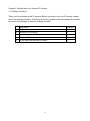
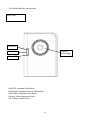
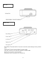
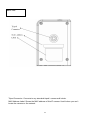
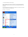
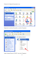
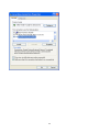
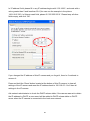
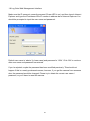
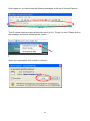


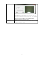
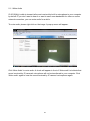
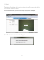
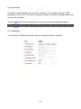

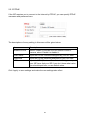

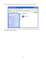
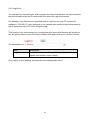
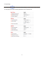
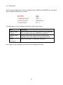

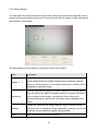
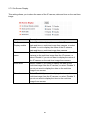
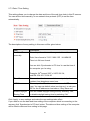
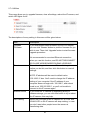

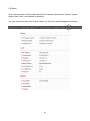
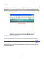

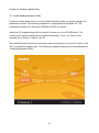

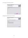
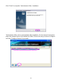
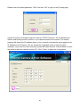
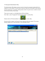
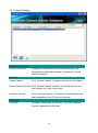
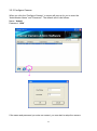
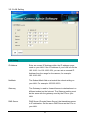
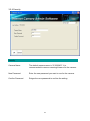

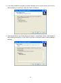
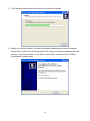


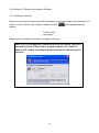
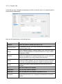

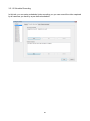

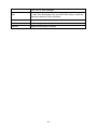

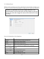
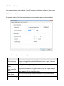

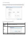


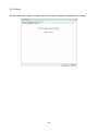
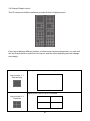
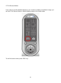
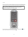
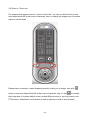
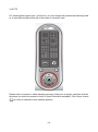
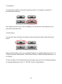
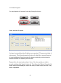


![Internet Camera - [ [ [ ANSEL ] ] ]](http://vs1.manualzilla.com/store/data/005837536_1-ce302c6b28431aa03d9b92e65549b72a-150x150.png)