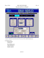
1
BAG/BOX MONITORS
MODEL BM-185D/285D/286D
OPERATION AND SERVICE MANUAL
Doc. #5016 Rev. A
August, 2006
Doc. # 5016
BM-185D/285D/286D
Operation and Service Manual
Rev. A
How to use this manual
Configuration tracking sheet: Record of system configuration, modifications, upgrades, etc.
Standard Warranty
Table of Contents
Section 1:
Provides a general description and specifications for the unit.
Section 2:
Inspection and installation (if required) instructions.
Section 3:
General operating and programming instructions.
Section 4:
Hardware theory of operation.
Section 5:
Calibration and periodic maintenance instructions.
Section 6:
Troubleshooting guide and diagnostic tools.
Glossary:
Definition of terms
Appendix A:
List of mathematical formulas that are used in TSA systems.
Parts Lists:
Detailed parts lists by subassembly including the manufacturer's
part numbers and instructions for ordering spare parts.
Drawings:
Drawings and schematic diagrams for the system.
Doc. # 5016
BM-185D/285D/286D
Operation and Service Manual
Rev. A
CONFIGURATION TRACKING SHEET
TSA MODEL NUMBER:______________ SERIAL NUMBER:_________________________
SOFTWARE VERSION:______________ DATE RECEIVED:_________________________
OPTIONS AND ACCESSORIES:__________________________________________________
_____________________________________________________________________________
SYSTEM MODIFICATIONS
MODIFICATION:_____________________________________________________________
____________________________________________________________________________
INSTALLED BY:_________________________________________
DATE:__________
MODIFICATION:_____________________________________________________________
____________________________________________________________________________
INSTALLED BY:_________________________________________
DATE:__________
MODIFICATION:_____________________________________________________________
____________________________________________________________________________
INSTALLED BY:_________________________________________
DATE:__________
MODIFICATION:_____________________________________________________________
____________________________________________________________________________
INSTALLED BY:_________________________________________
DATE:__________
Doc. # 5016
BM-185D/285D/286D
Operation and Service Manual
Rev. A
STANDARD WARRANTY FOR TSA SYSTEMS INSTRUMENTS
TSA Systems, Ltd. warrants this instrument to be free from defects in workmanship and
materials for a period of twelve months from the date of shipment, provided that the equipment
has been used in a proper manner and not subjected to abuse. At TSA's option, repairs or
replacements will be made on in-warranty instruments without charge at the TSA factory.
Warranty of sub-systems made by other manufacturers will be extended to TSA customers only
to the extent of the manufacturer's liability to TSA. TSA reserves the right to modify the design
of its product without incurring responsibility for modification of previously manufactured units.
Since installation conditions are beyond the company's control, TSA does not assume any risks
or liabilities associated with methods of installation or with installation results.
Every effort is made to keep the manuals up to date and accurate. However, because TSA
Systems is constantly improving and upgrading the product line, TSA can make no guarantee as
to the content of current manuals. No obligations are assumed for notice of change or future
manufacture of these instruments.
Manufactured by
TSA Systems, Ltd.
14000 Mead Street
Longmont, Colorado USA 80504-9698
Phone: +1.970.535.9949
FAX: +1.970.535.3285
Doc. # 5016
BM-185D/285D/286D
Operation and Service Manual
Rev. A
TABLE OF CONTENTS
1.0 INTRODUCTION........................................................................................................ 1
1.1 Scope and Purpose of Manual................................................................................1
1.2 General Description................................................................................................1
1.3 BM-285D/286D Specifications..............................................................................2
2.0 INSPECTION AND INSTALLATION.......................................................................3
2.1 Inspection...............................................................................................................3
2.1.1 Incoming Inspection......................................................................................3
2.1.2 Damage Claims.............................................................................................3
2.1.3 Storage...........................................................................................................3
2.1.4 Shipping.........................................................................................................3
2.2 Installation..............................................................................................................3
3.0 OPERATING INSTRUCTIONS................................................................................. 4
3.1 General Overview...................................................................................................4
3.2 Power-Up and Self-Tests........................................................................................5
3.2.1 Detector Detail..............................................................................................7
3.2.2 Tare Scale......................................................................................................8
3.2.3 Record Background.......................................................................................8
3.2.4 Update Background.......................................................................................8
3.2.5 Operator Log On...........................................................................................8
3.2.6 User Log Off.................................................................................................8
3.2.7 View MCA Scan...........................................................................................8
3.2.8 Set-up.............................................................................................................8
3.2.9 Utilities..........................................................................................................8
3.2.9 Set-up Waste Streams....................................................................................9
3.3 Normal Operation.................................................................................................10
Doc. # 5016
BM-185D/285D/286D
Operation and Service Manual
Rev. A
3.4 Programming the System.....................................................................................15
3.4.1 Set-Up Menu...............................................................................................16
3.4.1.1 Background Time............................................................................17
3.4.1.2 Background Method........................................................................17
3.4.1.3 Low Fault........................................................................................17
3.4.1.4 High Fault........................................................................................17
3.4.1.5 Variance Time.................................................................................17
3.4.1.6 Variance Trials................................................................................17
3.4.1.7 Units of Weight...............................................................................17
3.4.1.8 Minimum Weight............................................................................17
3.4.1.9 Reports.............................................................................................18
3.4.1.10 Report Type...................................................................................18
3.4.1.11 Label Printing................................................................................18
3.4.1.12 BM Identification..........................................................................18
3.4.1.13 User Waste Stream........................................................................18
3.4.1.14 Units..............................................................................................18
3.4.1.15 Force Background.........................................................................18
3.4.1.16 Notify User if SCALE Drifts.........................................................19
3.4.1.17 TARE Scale Type..........................................................................19
3.4.1.18 Intermec Printer Support...............................................................19
3.4.1.19 Notify User if SCALE Drifts.........................................................19
3.4.1.20 Prompt for Waste Item ID Before a Scan......................................19
3.4.1.21 Enable Scale Auto-TARE And Drift Alerts..................................19
3.4.1.22 Enable Two Energy Windows on Waste Streams.........................19
3.4.1.23 Disable Scale Controller and SPACT Alarm Logic......................19
3.4.1.24 Use MDA Calculator for Dynamic Alarm Levels.........................19
3.4.1.25 Print Sample Data button..............................................................20
3.4.2 Set-Up Waste Streams.................................................................................20
3.4.2.1 Name of Waste Stream....................................................................21
3.4.2.2 Count Time......................................................................................22
3.4.2.3 Count Display..................................................................................22
3.4.2.4 MCA Data.......................................................................................22
3.4.2.5 Alarm Message................................................................................22
3.4.2.6 Clean Message.................................................................................22
3.4.2.7 Alarm Type......................................................................................23
3.4.2.8 Efficiency........................................................................................23
3.4.2.9 Alarm Level.....................................................................................23
3.4.2.10 False Alarm Rate...........................................................................24
3.4.2.11 Confidence Level..........................................................................24
3.4.2.12 Maximum Weight..........................................................................24
3.4.3 Set Discriminators.......................................................................................25
Doc. # 5016
BM-185D/285D/286D
Operation and Service Manual
Rev. A
3.4.4 Variance.......................................................................................................26
3.4.5 Efficiency Check.........................................................................................27
3.5 Diagnostics and Utilities......................................................................................29
3.5.1 Operator Setup.............................................................................................29
3.5.2 Calibrate Electronics...................................................................................30
3.5.2.1 Calibration To Do List....................................................................30
3.5.2.2 Event Log........................................................................................30
3.5.2.3 Detector Information.......................................................................30
3.6 Reports..................................................................................................................31
3.7 Set-Up Checklist...................................................................................................32
3.8 BM-185D/285D/286D Waste Stream Set-Up Worksheet....................................33
4.0 THEORY OF OPERATION......................................................................................34
4.1 General Overview.................................................................................................34
4.2 Components..........................................................................................................34
4.2.1 Component Locations..................................................................................34
4.2.2 Computer and Power Supply.......................................................................35
4.2.3 Low Voltage Power Supply........................................................................35
5.0 MAINTENANCE........................................................................................................36
5.1 Operator Maintenance..........................................................................................36
5.2 Calibration............................................................................................................36
5.3 Discriminator Adjustment....................................................................................37
5.4 Weight Calibration...............................................................................................37
5.5 MCA Calibration (optional).................................................................................37
5.6 Calibration Checklist............................................................................................38
6.0 TROUBLESHOOTING............................................................................................. 39
6.1 Diagnostic Tools...................................................................................................39
6.1.1 Variance.......................................................................................................39
6.1.2 Efficiency Check.........................................................................................39
6.1.3 Com Port Setup...........................................................................................40
6.2 Fault Isolation.......................................................................................................41
6.3 Computer..............................................................................................................41
6.4 Signal Interface Assembly and Detectors............................................................41
6.5 Load Cell Central Calibration..............................................................................42
GLOSSARY......................................................................................................................43
APPENDIX A....................................................................................................................44
Spare Parts Ordering Information......................................................................................47
List of Drawings................................................................................................................. 49
Doc. # 5016
BM-185D/285D/286D
Operation and Service Manual
Rev. A
Doc. # 5016
BM-185D/285D/286D
Operation and Service Manual
Rev. A
1.0 INTRODUCTION
1.1 SCOPE AND PURPOSE OF MANUAL
This manual is designed to enable operating and service personnel to properly operate and care
for the BM-185D/285D/286D. Since applications are necessarily site-specific, operation
procedures are given in general terms. Service and repair are covered to the board level.
1.2 GENERAL DESCRIPTION
TSA's Barrel Monitor, Model BM-185D/285D/286D, is a large barrel monitoring device,
designed to screen bulky items of up to 1,000 pounds (454kg) for radioactive contamination. It
uses six plastic scintillation detectors, one on each side of the chamber. An optional sodium
iodide scintillation detector can be provided for spectral monitoring.
Operation of the instrument is controlled from a touch screen LCD monitor or optionally using
an external computer keyboard. All access is controlled by user-assigned password protection. A
printer can be connected for report printing or the printing of container data labels.
The instrument performs a self-test and acquires a new background count each time it is powered
up. It also monitors its own operation during normal use and indicates any failures. It runs
continuously, updating backgrounds whenever no weight is detected inside the chamber. A new
count is initiated every time a door open/door close sequence is detected.
The BM-185D/285D/286D displays the total activity, scaled to appropriate units (µCi, nCi, etc.)
and specific activity in pCi/gram or nCi/gram. These units are also included in reports and data
sample information that are created by the unit.
The unit operates on 100-240Vac, 50-60Hz power with circuit breaker protection.
PAGE 9
Doc. # 5016
BM-185D/285D/286D
Operation and Service Manual
Rev. A
1.3 BM-285D/286D SPECIFICATIONS
Input Power:
100-240Vac, 50-60 Hz, 6A
Detectors 285:
Detectors 286:
Two 12" x 19" x 1.5" (30.5cm x 48.2cm x 3.8cm) plus four 12" x
25" x 1.5" (30.5cm x 63.5cm x 3.8cm) plastic scintillation detectors
coupled to photo-multiplier tubes via light pipes.
Two 12" x 24" x 1.5" (30.5cm x 60.9cm x 3.8cm) plus four 12" x
35" x 1.5" (30.5cm x 88.9cm x 3.8cm) plastic scintillation detectors
coupled to photo-multiplier tubes via light pipes. Total detector volume is
3,384 in3 (55 liters)
Optional Detector:
One 3" x 3" NaI(Tl)
Sensitivity:
See Acceptance Data
Scan Time:
1 to 50,000 seconds, user-programmable
Background Time:
20 to 10,000 seconds, user-programmable
Sample Weight 285: 5 to 500lb (2.3 to 230kg)
Sample Weight 286: 5 to 1,000lb (2.3 to 455kg)
Serviceability:
May be repaired to the board/subassembly level in the field
Unit Weight 285:
Unit Weight 286:
10,000lb (4,545kg) with 1 3/4" lead shielding
12,000lb (5,455kg) with 1 3/4" lead shielding
Dimensions 285:
Dimensions 286:
61" high x 40" wide x 44" deep (154.9cm x 101.6cm x 110cm)
74" high x 44" wide x 45" deep (188cm x 110cm x 114.3cm)
Internal Cavity 285: 31" high x 24" wide x 27" deep (78.7cm x 60.9cm x 68.5cm)
Internal Cavity 286: 44" high x 28" wide x 28" deep (110cm x 70cm x 70cm)
Temperature Range: Operating:
Storage:
32 to 100°F (0 to 40°C)
0 to 120° F
PAGE 10
Doc. # 5016
BM-185D/285D/286D
Operation and Service Manual
Rev. A
2.0 INSPECTION AND INSTALLATION
2.1 INSPECTION
2.1.1 Incoming Inspection
Immediately inspect the system for mechanical damage, scratches, dents, or other defects. It
should be examined for evidence of concealed damage, as well as external disfigurement.
2.1.2 Damage Claims
If the system is damaged in transit or fails to meet specifications upon receipt, notify the carrier
and TSA Systems immediately. Shipping cartons, packing materials, waybills, and other such
documentation should be preserved for the carrier's inspection. TSA will assist in providing
repair or replacement of the system as necessary.
2.1.3 Storage
Care should always be taken to avoid subjecting the system to severe mechanical or electrical
shock. The system should be stored in a dry location and in a temperature range of 0 to 50°C.
2.1.4 Shipping
Before returning the system for any reason, notify TSA Systems of the difficulty encountered.
Please be prepared to give the model and serial numbers of the equipment. TSA will furnish
precise shipping instructions.
2.2 INSTALLATION
The system is complete and ready to operate when it is shipped. The tablet PC, stored inside the
chamber, must be mounted to the system. Mount the PC with the screws provided on the right
side and connect the following cables.
System AC
Speaker
PC AC
SC-770 Controller RS-485
The power cord located on the right of the unit plugs into a standard 100-240 volt, 47-63 Hz ac
receptacle provided on the controller enclosure. When the system is installed at its operating
location, perform the set-up described in section 3.1. General Overview should be performed.
PAGE 11
Doc. # 5016
BM-185D/285D/286D
Operation and Service Manual
Rev. A
3.0 OPERATING INSTRUCTIONS
3.1 GENERAL OVERVIEW
When the BM-185D/285D/286D is initially installed at its operating location, the operating
parameters must be adjusted to meet the local conditions and testing requirements. Most of the
adjustments are accessed via the software set-up mode.
A touch screen keyboard will appear any time you are required to enter data into the system.
Use of the provided stylus will help in accessing buttons and entering information.
A "Set-Up Checklist and a Waste Stream Programming Worksheet" can be found at the end of
this section. The Set-Up Checklist should be duplicated and filled in for each test source that will
be used with the system. A copy of the completed form should be kept in a convenient location
as a reference for identifying future problems. The Waste Stream Programming Worksheet
contains entries for each of the operating parameters in the individual waste streams. The system
permits up to 20 pre-programmed waste streams, and the form may be copied as required to
assist in programming these waste streams.
The set-up mode is password protected, with two levels of user access provided. Both level 0 and
level 1 operators have access to the normal operation of the BM-185D/285D/286D. Operators
with level 0 (administrative) access may change operating parameters and change discriminator
settings.
Determining the operating parameters is largely dependent on local requirements and conditions.
PAGE 12
Doc. # 5016
BM-185D/285D/286D
Operation and Service Manual
Rev. A
3.2 POWER-UP AND SELF-TESTS
The main power switch is located on the right side of the BM-185D/285D/286D.
When the system is turned on the computer performs a Power-On Self-Test (POST) which
checks and initializes the system hardware. At the end of this test, an audible 'beep' is sounded. If
the beep fails to sound during start-up, there may be a problem with audible alarms during
sample testing.
The operating system (Windows 2000) is then loaded from the hard disk. The program can be
run from the desktop shortcut, or directly from its location on the HDD. If the system fails to
power up correctly, try turning the power switch on the side of the controller module off for a
few seconds and then back on to re-initiate the tests.
Once the computer has successfully completed its tests and the program is executing, the system
will display the normal background collection screen. The detector windows should be gray, and
a pop-up window displaying the message "GETTING nn SECOND BACKGROUND" will
appear. The chronograph will show the remaining time of the count.
As soon as the background count is completed (the time is determined by the current entry in the
Set-Up Menu), the operator must log-on before any operations can be preformed. A scale tare is
recommended at this time. After the scale tare is complete, the blue "READY" window will
light, and the current background in counts per second will be displayed in black text on a blue
background. The detector windows are positioned graphically to indicate which detectors they
represent. If a background fault condition (either high or low) is detected the detector windows
will be displayed in black text on a magenta background. The errant detectors will display either
"**HI**" or "**LO**". The fault condition must be corrected before operation will be allowed.
PAGE 13
Doc. # 5016
BM-185D/285D/286D
Operation and Service Manual
A menu is displayed across the bottom of the screen. The available functions are:
Level One Access
Detector Detail
TARE Scale
Record Background
Update Background
Operator Log-On
Operator Log-Off
PAGE 14
Rev. A
Doc. # 5016
BM-185D/285D/286D
Operation and Service Manual
Rev. A
Level Zero Access (password protected)
View MCA Scan
Setup Menu
Utilities
Setup Waste Streams
3.2.1 Detector Detail
After a scan of an item in the chamber, this screen shown below will give the user the initial
background for the scan as well as the Net CPS, the Gross CPS, the Net Scan, or the Gross Scan
depending on which is selected in the Setup Waste Streams menu.
PAGE 15
Doc. # 5016
BM-185D/285D/286D
Operation and Service Manual
Rev. A
3.2.2 Tare Scale
Prompts the operator to verify that the chamber is empty and press the OK button to tare the
scale.
3.2.3 Record Background
For future use
3.2.4 Update Background
This button is used to force a background update of the system.
3.2.5 Operator Log On
Is used to log a new user onto the system. A user must be logged on to the system before any
samples are tested. The new user will be prompted for both name and badge number. Logging on
a new user automatically logs off the existing user.
For initial setup use: User name - TIM, Badge - 11, Password - OK. Delete this record after you
have entered your information.
3.2.6 Operator Log Off
Is used to log the current user off the system to prevent unauthorized access when the machine is
left unattended.
3.2.7 View MCA Scan
Opens a separate window that displays the spectrum if the unit is equipped with the optional
MCA. When the MCA is enabled it will accumulate data in the background during a scan.
3.2.8 Setup Menu
Allows the system's operating parameters to be examined or changed.
3.2.9 Utilities
Provides access to diagnostics, user setup and shut down utilities. Details of these functions are
provided in the appropriate sections of this manual.
PAGE 16
Doc. # 5016
BM-185D/285D/286D
Operation and Service Manual
3.2.10 Set-Up Waste Streams
Allows the operator to enter the parameters for the various waste streams.
PAGE 17
Rev. A
Doc. # 5016
BM-185D/285D/286D
Operation and Service Manual
Rev. A
3.3 NORMAL OPERATION
An operator must be "logged on" before the system can be operated. To Log On the operator
must press the Log On button and type the operator I.D. and press <Enter>, then type the badge
number and press <Enter>, and then type the password and press <Enter>.
NOTE: To prevent unauthorized use of the system, the operator must log off by pressing the log
off button whenever the unit is left unattended.
After the initial background has been collected and an operator has logged onto the system, the
monitor is ready for operation.
Place the container to be scanned on the weight scale platform and close the door to initiate a
scan. The monitor will read the scale when the door is closed.
If no weight (<5lb) is detected in the chamber, the monitor will return to background update
mode.
If the weight >5lb but less than the programmed minimum weight is detected, the screen will
display "Insufficient Weight". The operator must remove the weight from the chamber and press
OK to continue operation.
PAGE 18
Doc. # 5016
BM-185D/285D/286D
Operation and Service Manual
Rev. A
If the weight is ≥ the programmed minimum weight, the operator will be prompted to select the
appropriate waste stream from a menu. If an invalid waste stream is entered (e.g., no efficiency)
the operator will be given the opportunity to correct the entry. If a valid waste stream is entered
the item to be scanned will be compared to the maximum weight of the waste stream. If the item
is ≥ the maximum weight of the waste stream a dialog box will appear indicating the maximum
weight of the waste stream has been exceeded.
PAGE 19
Doc. # 5016
BM-185D/285D/286D
Operation and Service Manual
Rev. A
At this point the article may be removed or the operator may press OK as prompted by the
monitor and the waste stream menu will reappear.
After a valid waste stream is entered, the operator will be prompted for an Item I.D. A touch
screen keyboard will appear and the operator must type the I.D. or press <Enter> if no item I.D.
is required. The monitor will then scan the item and show the time to completion.
PAGE 20
Doc. # 5016
BM-185D/285D/286D
Operation and Service Manual
Rev. A
When the scan is complete, the unit will sound a "chime". If the activity measured is greater than
the alarm threshold, the alarm window at the top of the screen will turn red and a scan result box
will appear with the user-programmed alarm message in yellow letters on a blue background. If
the activity measured is less than the alarm threshold, the clear window at the top of the screen
will turn blue and a scan result box will appear with the user-programmed Clean message in
yellow letters on a blue background. The print button can be touched in the scan results box for a
print out of the scan data. The data includes waste stream name, date, time, waste item I.D., scan
message, activity in nCi, specific activity in (nCi/kg), kilogram weight, net counts per second,
and user information.
The screen will display the results of the scan, and hold this information until the door is opened.
When the door is opened, the scan information is cleared. The system is now ready for a new
sample.
PAGE 21
Doc. # 5016
BM-185D/285D/286D
Operation and Service Manual
PAGE 22
Rev. A
Doc. # 5016
BM-185D/285D/286D
Operation and Service Manual
Rev. A
3.4 PROGRAMMING THE SYSTEM
Programming the system can only be done by a "level 0 operator." The general set-up sets the
global system parameters, which are detailed in section 3.4.1. Set-Up Menu. Setting up waste
streams involves setting the parameters for the individual waste I.D.s; these parameters are
detailed in section 3.4.2, Set-Up Waste Streams.
When a large amount of data is to be entered we suggest you use an external keyboard.
PAGE 23
Doc. # 5016
BM-185D/285D/286D
Operation and Service Manual
3.4.1 Set-Up Menu
(Set-up is used to refer to the parameters that are common to all waste types.)
The menu will look something like this:
PAGE 24
Rev. A
Doc. # 5016
3.4.1.1
BM-185D/285D/286D
Operation and Service Manual
Rev. A
Background Time
Background time in seconds. Enter a value between 20 and 10,000.
3.4.1.2
Background Method
Two methods of background count are incorporated in the BM-185D/285D/286D. They are
selectable from the Set-Up Menu. The Rolling background method is the standard for TSA
products; for a count time of N seconds, the count is updated every N/10 seconds, and the sum of
the last 10 count periods are averaged to determine the current background. The Standard
background method simply counts for N seconds.
3.4.1.3
Low Fault
Low alarm level in CPS. The point at which the unit will generate a FAULT condition. Enter a
value between 0 and 1,000. The counts from each detector are compared to this value; if the
count from any detector falls below this value the unit will enter a FAULT mode.
3.4.1.4
High Fault
High alarm level in CPS. The point at which the unit will generate a FAULT condition. Enter a
value between 500 and 32,000. The counts from each detector are compared to this value; if the
count from any detector exceeds this value the unit will enter a FAULT mode.
3.4.1.5
Variance Time
Time per variance test in seconds. Enter a value between 10 and 100. Refer to section 3.4.4,
Variance, for details.
3.4.1.6
Variance Trials
Number of iterations for a Variance test. Enter a value between 3 and 10.
3.4.1.7
Units of Weight
Selects either pounds or kilograms as the unit of weight for display and report purposes.
If kilograms is selected then the Minimum Weight will be in kilograms. If pounds is selected the
Minimum Weight will be in pounds.
3.4.1.8
Minimum Weight
The minimum weight required before a scan may be initiated.
PAGE 25
Doc. # 5016
3.4.1.9
BM-185D/285D/286D
Operation and Service Manual
Rev. A
Reports
Enables writing a report to disk. Choose from three options, ALARM, ALL, or OFF. Refer to
section 3.6, Reports, for details.
3.4.1.10 Report Type
Enables the user to select either Text or CSV (comma separated value). CSV is useful if the data
is going into a spreadsheet.
3.4.1.11 Label Printing
If Manual is selected, each time the user requires a label they will be required to click on a print
button to print the label. If Automatic is selected, a label will be automatically printed after each
scan. The user will not be required to click on a print button.
3.4.1.12 BM Identification
This is the identification for the monitor. This ID will be included in the reports and data sample
information. Enter any combination of eight alpha-numeric characters.
3.4.1.13 User Waste Stream
This entry allows the system administrator to allow all operators access to any or all of 20
available waste streams. If this entry is set to "0", the operator must select the appropriate waste
stream for each item to be scanned. If set to 1 - 19, the operator will only be able to use the waste
stream selected by the system administrator. This is a global entry that applies to all operators.
3.4.1.14 Units
Allows the user to set the units to Curie (will autoscale to Ci, µCi, nCi, etc.), Bequerel, or
nanocurie.
3.4.1.15 Force Background
Background timeout so the unit will force a new background after a user-defined period of time.
If the unit is scanning a drum at the time, it will wait until the current scan is completed before
getting new background.
PAGE 26
Doc. # 5016
BM-185D/285D/286D
Operation and Service Manual
Rev. A
3.4.1.16 Notify User if SCALE Drifts
If enabled, allows the user to enter the amount of drift that is allowed by the monitor before it
informs the user that a hardware tare is recommended. A value of zero disables informing the
user about scale drift.
3.4.1.17 TARE Scale Type
Allows the user to select if a TARE is going to be done through Software or Hardware.
3.4.1.18 Intermec Printer Support
If enabled, will allow the printing of labels sized specifically for Intermec printers.
3.4.1.19 Display Negative Scan Results
When selected, all values whether positive or negative that are part of the Scan sum will be
displayed.
3.4.1.20 Prompt for Waste Item ID Before a Scan
If disabled, a "WASTE ITEM ID" prompt will not be displayed when performing scans.
3.4.1.21 Enable Scale Auto-TARE And Drift Alerts
When selected, this feature causes the scale to automatically TARE at startup and also activates
the user selectable amount of drift allowable before a Drift Alert is activated.
3.4.1.22 Enable Two Energy Windows on Waste Streams
Allows the user to adjust two sets of discriminators in order to establish both a low and a high
energy window.
3.4.1.23 Disable Scale Controller and SPACT Alarm Logic
If a BM-285D has no scale, selecting this feature will provide a way for the user to manually
start a Scan.
3.4.1.24 Use MDA Calculator for Dynamic Alarm Levels
Provides an automatic way for the system to calculate the minimum alarm threshold and adjust
for changing backgrounds.
PAGE 27
Doc. # 5016
BM-185D/285D/286D
Operation and Service Manual
Rev. A
3.4.1.25 Print Sample Data button
Provides a method to perform a printer test.
3.4.2 Setup Waste Streams
Clicking the Setup Waste Streams button will first bring up the screen shown below. This allows
the user to select the individual waste stream to be initially established or modified.
PAGE 28
Doc. # 5016
BM-185D/285D/286D
Operation and Service Manual
Rev. A
Selecting an individual waste stream will then cause the screen shown below to be displayed.
A detailed description of each entry follows:
3.4.2.1
Name of Waste Stream
Provides a description of the waste stream. The operator may program up to 16 alpha-numeric
characters to provide a unique reference for each waste stream. The existing I.D. will be
displayed.
PAGE 29
Doc. # 5016
3.4.2.2
BM-185D/285D/286D
Operation and Service Manual
Rev. A
Count Time
Scan time, in seconds. Enter a value between 1 and 10,000.
3.4.2.3
Count Display
Selects the method used for displaying counts on the screen and in the reports. The background
counts will always be displayed in counts/second. The count display options only control the
display after a scan. The available options are:
1.
Total counts per scan: Displays total counts per scan time.
2.
Net counts per scan: Displays counts per scan time above background.
3.
Total counts per second: Displays total counts per second.
4.
Net counts per second: Displays counts per second above background.
3.4.2.4
MCA Data
On/Off to enable or disable MCA data acquisition. This selection is only valid on units equipped
with the optional MCA and NaI(Tl) detector.
3.4.2.5
Alarm Message
The message that will be displayed if the alarm level is exceeded. This may be up to 22 alphanumeric characters. This message will be included on the data sample information and in the
reports.
3.4.2.6
Clean Message
The message that will be displayed if the alarm level is not exceeded. This may be up to 22
alpha-numeric characters. This message will be included on the data sample information and in
the reports.
PAGE 30
Doc. # 5016
3.4.2.7
BM-185D/285D/286D
Operation and Service Manual
Rev. A
Alarm Type
Selects method of generating a radiation alarm. The available options are:
1.
NSigma: ((N*√background) + background)
2.
nCi: nanoCuries above background
3.
SPACT: Specific Activity
3.4.2.8
Efficiency
The efficiency of the detectors, in percent, to the source activity. This value is used in calculating
the activity. This value may be either entered manually or automatically calculated by the
BM-185D/285D/286D. Press on the white box and enter a value, or press auto to allow the unit
to calculate the efficiency.
1.
Manual entry method: Enter efficiency in percent.
2.
Automatic calculation: The operator will be prompted for a count time (in
seconds) and the calibration source activity (in nanoCuries). Press BEGIN, at
which time a START button will appear. Press the START button and the unit
will then take an nn second background. The operator will be prompted to place
the source in the center of the chamber and press START to accumulate an nn
second count with the source in the chamber. The efficiency will be displayed in
the efficiency window.
3.4.2.9
Alarm Level
The operator will be prompted for the alarm level (depending on the alarm type selected above).
Enter the alarm level in the appropriate units. The previous value will be displayed, and will only
be accepted by entering it again or a new value may be entered.
1.
ACT: Activity is displayed in either nCi or Bq.
2.
N*Sigma: Radiation alarm level in N*Sigma (N*√background+background).
This is the count level that will generate a radiation alarm when N*Sigma alarm type is
selected. This value is used only when the Alarm Type is set to N*Sigma.
3.
SpAct: Radiation alarm level, above background, in pCi per kilogram or nCi per
kilogram.
PAGE 31
Doc. # 5016
BM-185D/285D/286D
Operation and Service Manual
Rev. A
3.4.2.10 False Alarm Rate
The factory default value is 1 in 100. Changing this value will change the MDA calculation and
will affect the sensitivity as well as the false alarm rate for the unit. Contact TSA for guidance in
adjusting this parameter.
3.4.2.11 Confidence Level
The factory default value is 95%. Contact TSA for guidance in adjusting this parameter.
3.4.2.12 Maximum Weight
Enter a maximum allowable weight, in pounds or kilograms. This value is used to determine if
the item to be scanned is within the waste stream weight limits. The maximum recommended
load for the BM-285 is 200 pounds (74.6 Kg) and the BM-286 is 1000 pounds (373.2 Kg.)
PAGE 32
Doc. # 5016
BM-185D/285D/286D
Operation and Service Manual
Rev. A
3.4.3 Set Discriminators
Clicking the Set Discriminators button will display the screen shown below. From this screen the
user can adjust the lower level discriminator (LLD) and upper level discriminator (ULD) to
achieve a detection window that will include the radiation energies that they need to detect while
blocking energies that they can ignore. Changing the LLD and the ULD will cause the Current
Detector Counts shown in the upper part of the screen to change as the energy window is
reduced or expanded.
PAGE 33
Doc. # 5016
BM-185D/285D/286D
Operation and Service Manual
Rev. A
3.4.4 Variance
The Variance program implements an algorithm to compute the statistical accuracy of counts
obtained from each of the six plastic detectors in the system. The number of passes run by the
program, and the sample time for each pass, are user selectable from the Set-Up Menu. (TSA
generally recommends three passes of 60 seconds each.)
At the end of each pass, four columns of information are displayed for each detector. The
columns contain, from left to right, the mean counts, the variance in counts (S2), the variance to
mean ratio, and the mean value of R. Readings in the third column (Var/Mean) should not
exceed 0.49. TSA's normal acceptance criterion is that, for the third pass, no detector should
show a mean value of R(Bar) (fourth column) greater than 0.30.
The results of each iteration are displayed and held until the results of the next iteration are
available. The results of the final iteration are held until the operator presses DONE.
PAGE 34
Doc. # 5016
BM-185D/285D/286D
Operation and Service Manual
Rev. A
3.4.5 Efficiency Check
The Calculation Setup box will appear and the operator will be prompted for a count time (in
seconds) and the calibration source activity (in nanoCuries). Then press BEGIN at which time a
START button will appear. Press the START button and the unit will then take an nn second
background. The operator will be prompted to place the source in the center of the chamber and
press START to accumulate an nn second count with the source in the chamber.
PAGE 35
Doc. # 5016
BM-185D/285D/286D
Operation and Service Manual
Rev. A
After nn second count, calculated efficiencies of the detectors and the overall efficiency of the
unit will be displayed, but not stored.
The overall efficiency is the sum of the efficiencies for the six plastic detectors as calculated with
a test source in the center of the counting chamber.
PAGE 36
Doc. # 5016
BM-185D/285D/286D
Operation and Service Manual
Rev. A
3.5 DIAGNOSTICS AND UTILITIES
When the operator presses the utilities button, he/she will be presented with the Utilities Menu.
Press the appropriate button from the menu above. The functions are as follows:
3.5.1 Operator Setup
Operators can be deleted or added by name, badge number, password and level of access
(Admin. or User). Be careful in selection of administrative access.
PAGE 37
Doc. # 5016
BM-185D/285D/286D
Operation and Service Manual
Rev. A
3.5.2 Calibrate Electronics
This button brings up the Detector recognition and calibration window shown below.
3.5.2.1
Calibration To Do List
Gives the user a method to determine where in the calibration cycle the system is.
3.5.2.2
Event Log
Documents the specific steps that are occurring for each item listed in the Calibration To Do
List. This gives the user the opportunity to review the results of each step.
3.5.2.3
Detector Information
This screen gives a graphic representation of each detector in the system. The individual detector
box will flash when it is time for its calibration and the information box will display what the
user is to do.
PAGE 38
Doc. # 5016
BM-185D/285D/286D
Operation and Service Manual
Rev. A
3.6 REPORTS
A file named Report_<current date>.txt is created and entries appended. A new file is
automatically created at midnight when the date changes. Text reports use the units from the
CSV main screen. Reports always use Bq/Kg or nCi/Kg.
The activity, specific activity, kilogram weight, and net cps are stored in float format.
The (Standard) Report output is controlled from the Set-Up Menu. Three options are offered:
None, Alarms, or All.
None disables report generation altogether.
Alarms generates a report only for samples that are found to be above the alarm level.
All causes a report to be generated and stored on disk every time a scan is completed.
PAGE 39
Doc. # 5016
BM-185D/285D/286D
Operation and Service Manual
Rev. A
3.7 SET-UP CHECKLIST
Plastic Detectors:
Background: __________Counts
Test Source:
Isotope: ___________ Activity: _________ nCi Serial No.:_______ Assay Date: ___________
No. of Counts:
Top: ____________ Bottom: ____________
Left: ____________ Right: ____________
Door: ____________ Rear: ____________ Overall: ____________
Efficiency:
Top: ____________ Bottom: ____________
Left: ____________ Right: ____________
Door: ____________ Rear: ____________ Overall: ____________
Upper Energy Window Discriminator Settings: LLD: _________ ULD: __________
Lower Energy Window Discriminator Settings: LLD: _________ ULD: __________
Set-Up Parameters:
Background Time: __________seconds
Background Method: [ ] Rolling
Variance Time: __________seconds
[ ] Standard
Number of Trials: __________
Low Alarm Level: __________counts/second
High Alarm Level: __________counts/second
Minimum Weight: __________pounds
Reports:
Units of Weight:
[ ] All [ ] Alarms
[ ] Lbs [ ] Kg
[ ] None
User Stream: ________
BM I.D.:____________________
Performed by: ______________________________________ Date: ____________________
PAGE 40
Doc. # 5016
BM-185D/285D/286D
Operation and Service Manual
Rev. A
3.8 BM-185D/285D/286D WASTE STREAM SET-UP WORKSHEET
Waste Stream number: ___________________________________
Waste I.D.:_______________________________________________ (16 characters max)
Count Time: _______________ seconds
MCA Data (Optional): [ ] On [ ] Off
Alarm Message: ___________________________________________ (22 characters max)
Clean Message: ____________________________________________ (22 characters max)
Maximum Weight: _____________________ pounds
Efficiency: _______________ %
Alarm Level: ___________________________ [ ] DPM [ ] N*Sigma [ ] pCi/g
PAGE 41
Doc. # 5016
BM-185D/285D/286D
Operation and Service Manual
Rev. A
4.0 THEORY OF OPERATION
4.1 GENERAL OVERVIEW
The BM-185D/285D/286D system is a self-contained Bag/Box monitor, operated by a PC. The
computer uses Windows 2000 operating system, with a touch screen, color LCD display to
monitor system operation. The system can be used with an external keyboard for operator input,
and a printer to generate reports, or labels. Operating parameters can be entered from the touch
screen or external keyboard via a password protected set-up menu.
The computer system continually monitors for fault conditions, and reports all errors on the
computer monitor. If the system detects a fault condition, it will not allow normal operation until
the fault condition is corrected.
4.2 COMPONENTS
4.2.1 Component Locations
Refer to Drawings 2 & 3.
Six plastic scintillation detector assemblies are contained within the walls and door of the main
assembly. An optional Sodium Iodide detector may also be included. A weight scale is in the
bottom of the enclosure. The scale controller is located in the top of the unit with the other
electronics.
PAGE 42
Doc. # 5016
BM-185D/285D/286D
Operation and Service Manual
Rev. A
4.2.2 Computer and Power Supply
Pentium® 4 Based Panel PC with Touch Screen display
• Panel mountable and VESA standard Arm mount
• Aluminum front panel meets NEMA 4 / IP65 standard
• 15" high brightness TFT LCD with LCD on/off switch
• Support Socket-478 base support Intel® Pentium 4 / Celeron up to 533 MHz FSB
• Resolution: 1024 x 768
• 200W Industrial ATX Power Supply
Dimensions: 16.15" x 12.17" x 4.03" (WxHxD)
4.2.3 Low Voltage Power Supply
Low voltage for the system is supplied by one open frame power supply which provides +12Vdc
for peripheral equipment.
PAGE 43
Doc. # 5016
BM-185D/285D/286D
Operation and Service Manual
Rev. A
5.0 MAINTENANCE
5.1 OPERATOR MAINTENANCE
The hinges and door latch do not require lubrication.
5.2 CALIBRATION
The detectors have been calibrated at the factory and the settings have been stored in the
controller. Because of the stability of the system there should be very little need to perform a
calibration in the field. If background readings are unusually high or low the user may wish to
perform a field calibration by using the following instructions.
Required items: a 137Cs source with a depreciated value from 1µCi to 10µCi.
If the user does not know the depreciated value of the calibration source but does know when the
source was manufactured, then the user can go to the TSA Systems web site (tsasystems.com)
and look under archives/software/ SourceDepr to determine the depreciated value.
The first thing the user must do is to select the Utilities button from the bottom of the main
screen. This will bring up the utilities menu. The user must then select the Calibrate Electronics
button to bring up the Detector Recognition and Calibration screen. To start the calibration the
user must select the Start Calibration button at the bottom of the screen.
The system controller will then take "roll call" to identify/verify the addresses of the DM-757s. If
the addresses haven't changed since the last time the unit was calibrated, it will continue with the
calibration. If it senses a conflict, the controller will instruct the DM-757 to pick random
addresses and will attempt to resolve the detector electronics. If communications fail after 3
attempts, the controller will tell the user which detector failed and halt operation. If detectors are
resolved successfully, calibration will continue.
After testing/resolving the detectors, the unit will flash the LEFT box associated with the left
detector that is now ready to be calibrated, then the user will be prompted:
Tape the source to the chamber liner wall as close to the middle of the LEFT detector as possible
and click “CONTINUE’ when ready
After the user places the source on the left detector and clicks the “CONTINUE” button the
controller will start the actual calibration.
PAGE 44
Doc. # 5016
BM-185D/285D/286D
Operation and Service Manual
Rev. A
NOTE:
When calibrating the bottom detector the source must be placed on the liner in the
center of the chamber not on the scale platform.
When the calibration for that detector is finished, the controller will flash the box on the screen
of the next detector to be calibrated. The user will move the source and click the “CONTINUE”
button again to start the next detectors calibration. This sequence will continue until all the
detectors have been calibrated.
At the conclusion of the calibration process the user should use the Calibration Checklist to log
all the HV DAC values now displayed in the detector boxes. This information will be useful for
identifying if there is a problem developing in either a detector or the detector electronics.
NOTE:
Clicking the Abort Calibration button will terminate the application.
If sometime during the calibration process a problem arises, the calibration process can be
stopped by clicking the Abort Calibration button. To ensure that the system is not left in an
unknown condition, the Restore Factory Calibration button should be clicked to return the
system to the factory calibration settings.
5.3 DISCRIMINATOR ADJUSTMENT
Settings for plastic Detectors
LLD = 0.073 volts = 16 keV
ULD = 5.0 volts = 1.1 MeV
NOTE: If either level is changed you must recalculate all of the waste stream efficiencies. The
unit will also acquire a new background when leaving the Utilities Menu. Always run a variance
after adjusting the levels.
5.4 WEIGHT CALIBRATION
The scale was calibrated at the factory and should not need calibration. If a problem occurs
contact TSA Systems for help.
5.5 MCA CALIBRATION (OPTIONAL)
Refer to the instruction manual for the MCA for its calibration procedures.
PAGE 45
Doc. # 5016
BM-185D/285D/286D
Operation and Service Manual
5.6 CALIBRATION CHECKLIST
HVDAC:
Left: _____________ Vdc Top: _____________ Vdc Right: _____________ Vdc
Door: _____________ Vdc Back: _____________ Vdc Bottom: _____________ Vdc
Variance (final readings only):
Number of trials: _____
Variance time: _____
Left: _______________ Top: _______________ Right: _______________
Door: _______________ Back: _______________ Bottom: _______________
Performed by: ______________________________
PAGE 46
Date: ____________
Rev. A
Doc. # 5016
BM-185D/285D/286D
Operation and Service Manual
Rev. A
6.0 TROUBLESHOOTING
6.1 DIAGNOSTIC TOOLS
There are several diagnostic tools available to help isolate problems in the unit. Access to the
diagnostics is available only to level 0 users with a valid password. The system administrator
normally controls the password access. Press Setup Waste Streams from the operating screen to
access the Waste Streams Menu. From the Waste Streams Menu, select the desired Waste
Stream. From that screen the following diagnostics may be selected:
6.1.1 Variance
Tests the statistics of the detector counts versus a Gaussian distribution. If periodic noise is being
counted the results of the variance test will approach 1.0. Light leaks will result in a variance
near 2.0. Refer to section 3.4.4 for details on the variance test.
6.1.2 Efficiency Check
Performs an efficiency calibration on the six plastic scintillation detectors. The results are only
displayed and are not written to disk.
Both the Variance and Efficiency are unique to each individual waste stream. Setting the
discriminators for one waste stream does not affect the discriminator settings for any other waste
stream. This gives the user the ability to fine tune each waste stream for optimal Variance and
Efficiency.
PAGE 47
Doc. # 5016
BM-185D/285D/286D
Operation and Service Manual
Rev. A
6.1.3 Com Port Setup
The BM-185D/285D/286D Com Port Setup menu allows the user to establish communications
links between the computer, the SC-770, and the Scale Controller. This operation should only be
necessary if communication has been lost from either one or both sources.
1.
Click on the Com Port Setup icon on the computer to bring up the screen.
2.
Click on the Scan Com Ports button.
3.
After both the SC-770 and the Scale Controller have been found a message will appear
telling you to save the comport settings. Click OK to clear this message.
4.
Click the Save Comport Settings button and then click the Cancel button to exit this screen.
5.
If at the end of the 10 trials the program does not find both the SC-770 and the Scale
Controller, close out the application and start the application again. If after a second set of
10 trials the computer has not found both sources contact TSA for assistance.
PAGE 48
Doc. # 5016
BM-185D/285D/286D
Operation and Service Manual
Rev. A
6.2 FAULT ISOLATION
When the program is executing on the PC there are two small dark green boxes in the lower left
hand of the display.
The SC-770 box should flash light green every second indicating that the SC-770 has sent data to
the PC.
The Scale box should flash light green upon receiving data from the scale controller. This occurs
when the door is closed.
If the system fails to operate properly, note all anomalies, and try to determine if or how they are
related. This will usually isolate the problem to some degree, and reduce the time required to
repair the system. Always perform a thorough visual inspection of the suspect assemblies,
looking for loose connectors, pinched and broken wires, burned components, and signs of
overheating. If nothing is found during the physical inspection, locate the problem area in the
following paragraphs, and isolate the defective assembly using the appropriate procedure.
NOTE: Always turn the power off when connecting or disconnecting components or cables.
6.3 COMPUTER
Use standard troubleshooting procedures on the PC.
6.4 SIGNAL INTERFACE ASSEMBLY AND DETECTORS
The detectors and detector electronics are located behind the chamber liner. This liner is very
heavy and awkward to remove and reinstall. It is recommended that TSA be contacted prior to
doing any liner removal.
PAGE 49
Doc. # 5016
BM-185D/285D/286D
Operation and Service Manual
Rev. A
6.5 LOAD CELL CENTRAL CALIBRATION
Front panel switches:
MENU (>): Pressing this will enter menu and advance to next menu item.
PEAK (>): Pressing this will select a menu item to allow adjusting parameters.
RESET (up arrow): Pressing this when adjusting parameters advances the parameter.
MENU (<) ALARMS: Pressing this will return to the previous menu item.
Field Calibration:
1.
Press MENU and "Lo In" is displayed. Make sure there is no weight on the platform.
2.
Press PEAK to take a Lo In reading. When value is displayed, press RESET to store the
value.
3.
Press MENU to advance to "Hi In". Place a known calibrated weight on the platform
before proceeding.
4.
Press PEAK to take a Hi In reading. When value is displayed, press RESET to store the
value.
NOTE: You can leave the weight on the platform to QC the calibration after the controller
resets.
5.
Press MENU, "Lo rd" is displayed. Press PEAK, Verify value is 00000. If value is
indeed 00000, then store the value by pressing MENU. If the value isn't 00000, make it so
and press RESET.
6.
Press MENU, "Hi rd" is displayed. Press PEAK and enter the weight that was on the
platform when "Hi In" was read. To do so, position the flashing digit over the number
requiring a change by pressing PEAK. Press RESET to increase the value of the digit.
When satisfied, press MENU to store the value. A 25lb weight would be entered as
025.00.
7.
Continue to press MENU until the unit resets.
8.
Verify the weight being displayed is the same as the weight that is on the platform.
PAGE 50
Doc. # 5016
BM-185D/285D/286D
Operation and Service Manual
Rev. A
GLOSSARY
ADC: Analog to Digital Converter, is an integrated circuit that converts an analog signal into a
binary number that can be used by the microprocessor.
CPS or cps: Counts Per Second
High Background Alarm/Fault: The condition that occurs if the counts exceed the programmed
high background level. This condition prevents further operation until the problem is corrected.
Normally set in cps.
LLD: The Lower Level Discriminator provides a threshold, usually adjustable, that determines
the lowest signal level that will be accepted as a nuclear pulse by the system's electronics. Some
systems have both upper and lower level discriminators that can be used to set a discriminator
window. The discriminator window can be used to effectively reduce the background counts, and
increase system sensitivity to certain isotopes.
Low Background Alarm/Fault: The condition that occurs if the counts fall below the
programmed high background level. This condition prevents further operation until the problem
is corrected. Normally set in cps.
POST: Power On Self Test
Rolling Background: This is the background accumulation method used in most of TSA's
instruments. Background accumulation is done in ten separate buffers, each buffer representing
1/10 of the total background time. As each buffer is filled, the background is updated. This
results in a background update at background time/10. Initial background accumulation requires
the full background time.
Standard Background: Standard background requires the full background time for the initial
background and updates.
ULD: The Upper Level Discriminator provides a threshold, usually adjustable, that determines
the highest signal level that will be accepted as a nuclear pulse by the system's electronics. Also
see LLD.
PAGE 51
Doc. # 5016
BM-185D/285D/286D
Operation and Service Manual
Rev. A
APPENDIX A
The following formulas are used in various systems manufactured by TSA Systems, Ltd. They
are provided to assist in verifying system operation and to give our customers a better
understanding of how the systems operate. This is a general list, but most systems use some of
these formulas.
ACTIVITY FROM COUNTS
Where:
Activity = Activity in nCi
Eff = Decimal efficiency (i.e. 10% = 0.10)
N = Net counts per second (cps - background cps)
37 = bq per nCi
EFFICIENCY
where:
N = cps with source - background cps
activity = test source activity in nCi
N*Sigma Alarm Level
Used to calculate the alarm level on instruments using n*sigma alarm algorithm. Most systems
that use n*sigma alarm levels operate in counts/second.
where:
bkg = Background counts
Sigma = 1bkg
N = N*Sigma value
PAGE 52
Doc. # 5016
BM-185D/285D/286D
Operation and Service Manual
Rev. A
RELIABLE DETECTABLE ACTIVITY (RDA) FORMULA
This formula calculates the minimum activity, in disintegrations per minute that can be reliably
detected under a given set of operational conditions.
BKG = total background counts per count time
CON = confidence sigma
CT = count time in seconds
E = Decimal efficiency (i.e. 10% = 0.10)
F = false alarm level in cps
FA = false alarm sigma
G = intermediate variance
RDA = reliable detectable activity in DPM
SIGNAL TO BACKGROUND RATIO
The following formula is helpful in determining the optimum discriminator settings. Always
perform a variance test at the final setting of the lower-level discriminator to ensure that system
noise is not being introduced into the amplifier stage.
S
Q = √B
where:
Q = Quality factor
S = Net signal (count with source - background)
B = Background count
Higher values of Q result in better sensitivity.
PAGE 53
Doc. # 5016
BM-185D/285D/286D
Operation and Service Manual
Rev. A
VARIANCE
The variance analyzer mode is used to check whether the counts seen by the controller are
actually from the proper distribution. If the distribution approaches normal, the resulting number
will approach 0. Any significant deviation from the normal distribution will result in a larger
number. The two most common problems resulting in variance failure are light leaks in the
detectors, and periodic noise in the electronics. Periodic noise will result in a number of about 1,
a light leak will usually result in a number larger than 2. The number displayed during a variance
test is the absolute value of the average of a number of these tests, with one test being performed
every nn seconds. The data is valid after three iterations of nn seconds. The pass/fail criteria vary
from unit to unit and are included in the variance section of the manual on most units.
where:
C = counts per sample time
_
C = mean counts
I = number of iterations
N = number of samples taken
R = sample variance modified to equal 0, rather than 1, for Gaussian distribution
_
R = mean variance, this term is referred to as variance in TSA’s manuals
S2 = sample variance
PAGE 54
Doc. # 5016
BM-185D/285D/286D
Operation and Service Manual
Rev. A
SPARE PARTS ORDERING INFORMATION
To facilitate the processing of spare parts orders the following information is required.
Product Number
Product Serial Number
TSA Stock number
Part description (from parts list)
When ordering programmed PROMs, the software version is required. This can be found on the
PROM label.
NOTE: MODEL NUMBER SUFFIXES ARE GENERALLY NOT INCLUDED IN THE
TEXT OF THE MANUAL. HOWEVER, THE SUFFIXES IN THE PARTS LISTS MUST
BE INCLUDED ON ORDERS FOR SPARE PARTS.
FOR ASSISTANCE CALL:
TSA Systems, Ltd.
14000 Mead Street
Longmont, Colorado USA 80504-9698
Phone: +1.970.535.9949
FAX: +1.970.535.3285
PAGE 55
Doc. # 5016
BM-185D/285D/286D
Operation and Service Manual
Rev. A
BM-185D/285D/286D
TSA #
DESCRIPTION
MANUFACTURER / SUPPLIER
0079A
0080
0401
LOAD CELL CONTROLLER
SCALE PLATFORM
COMPUTER
3226C
3227
6463B
7814A
8253
8674B
9411A
315927
315928
315925
315924
315923
315926
COMPUTER MOUNTING ARM
MSC, RELEASE LEVER
MSC, PULL HANDLE
POWER SUPPLY, 15V, 5A
SW, PROXIMITY SENSOR 3/4”
DM-757A DETECTOR MODULE
GHA-472B
SC-770 CONTROLLER
12 X 19 TOP DETECTOR
12 X 19 BOTTOM DETECTOR
12 X 25 LEFT DETECTOR
12 X 25 REAR DETECTOR
12 X 25 RIGHT DETECTOR
12 X 25 DOOR DETECTOR
LOAD CELL CENTRAL-VPI-SC
LOAD CELL CENTRAL CWP-24.5 X 19.5-200 LB
PPC150S478TSR Epicenter 15" TFT LCD Pentium® 4
Based Panel PC with Touch Screen Resistive
iBASE PPC-5150W-AL-R30/POS
TSA 3226C
TSA 3227B
MEAN WELL S-60-15
SENTROL 1078C
TSA-8253
TSA-8674B
TSA-9411A
TSA
TSA
TSA
TSA
TSA
TSA
PAGE 56
Doc. # 5016
BM-185D/285D/286D
Operation and Service Manual
Rev. A
LIST OF DRAWINGS
Title
Drawing
BM-285D Manual...................................................................................................................... 1
BM-285D Wiring Diagram.........................................................................................................2
BM-285D Panel PC Connections................................................................................................3
SC-770AS External View........................................................................................................... 4
SC-770AS Wiring Diagram........................................................................................................ 5
SC-770AS Internal View............................................................................................................ 6
TPM Detector Module DM-757 Sheet 1 of 2.............................................................................. 7
TPM Detector Module DM-757 Sheet 2 of 2.............................................................................. 8
DM-757 Board Component Designator...................................................................................... 9
GPRB-756 General Purpose Relay Board.................................................................................10
GPRB-756 Component Designator........................................................................................... 11
GHA-472A Neutron High Voltage Analog Schematic Diagram Sheet 1 of 2............................12
GHA-472A Neutron High Voltage Analog Schematic Diagram Sheet 2 of 2............................13
GHA-472A Neutron High Voltage Analog Schematic Diagram Sheet 3 of 3............................14
GHA-472A Board Component Designator..............................................................................15
Schematic Diagram – PCB Differential Transmitter...............................................................16
TRAN-1 Component Designator.............................................................................................17
Voltage Divider PMT R580/4.7M/Poly Cap...........................................................................18
PAGE 57