1
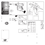
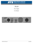
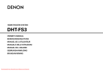
MODEL BP-325
Belt-pack Intercom Station
User Manual
I
II
9350-5690-00 Rev. M 8/2008
PROPRIETARY NOTICE
SHIPPING TO THE MANUFACTURER
The product information and design disclosed herein were originated by
and are the property of Telex Communications, Inc. Telex reserves all
patent, proprietary design, manufacturing, reproduction, use and sales
rights thereto, and to any article disclosed therein, except to the extent
rights are expressly granted to others.
All shipments of product should be made via UPS Ground, prepaid (you
may request from Factory Service a different shipment method). Any
shipment upgrades will be paid by the customer. The equipment should
be shipped in the original packing carton. If the original carton is not
available, use any suitable container that is rigid and of adequate size. If
a substitute container is used, the equipment should be wrapped in paper
and surrounded with at least four (4) inches of excelsior or similar
shock-absorbing material. All shipments must be sent to the following
address and must include the Proof of Purchase for warranty repair.
Upon completion of any repair the equipment will be returned via
United Parcel Service or specified shipper, collect.
COPYRIGHT NOTICE
Copyright 2007 by Telex Communications, Inc. All rights reserved.
Reproduction, in whole or in part, without prior written permission from
Telex is prohibited.
WARRANTY NOTICE
See the enclosed warranty card for further details.
CUSTOMER SUPPORT
Technical questions should be directed to:
Customer Service Department
RTS/Telex Communications, Inc.
12000 Portland Avenue South
Burnsville, MN 55337 USA
Telephone: 800-392-3497
Fax: 800-323-0498
Factory Service: 800-553-5992
RETURN SHIPPING INSTRUCTIONS
Customer Service Department
Telex Communications, Inc. (Lincoln, NE)
Telephone: 402-467-5321
Fax: 402-467-3279
Factory Service: 800-553-5992
Please include a note in the box which supplies the company name,
address, phone number, a person to contact regarding the repair, the type
and quantity of equipment, a description of the problem and the serial
number(s).
Factory Service Department
Telex Communications, Inc.
8601 East Cornhusker Hwy.
Lincoln, NE 68507 U.S.A.
Attn: Service
This package should include the following:
Qty
Description
Part No.
1
Final Assy, BP325, Gray
9010673800
Final Assy, BP325, Rev
2.0
9010673820
Final Assy, BP325, Black
9010673821
1
User Manual
9350569000
1
Warranty Statement
38110387
1
EMC & LVD Statement
38109675
Table
Of
Contents
Chapter 1 - Connections And Operation
Connections ................................................................................................................................................. 1
Headset ........................................................................................................................................................ 1
Intercom Channels ...................................................................................................................................... 1
Operation .................................................................................................................................................... 2
Programmable Options ............................................................................................................................... 3
Factory Settings .......................................................................................................................................... 3
Jumpers (W1-w7) ........................................................................................................................................ 4
Sidetone Adjustment .................................................................................................................................... 5
Alternate Powering Methods ...................................................................................................................... 5
General ........................................................................................................................................................ 5
Method One: One Channel Operation With A Non-rts Power Supply ....................................................... 5
Line Input Connector Wiring For 1-channel Operation With Non-rts Power Supply ................................ 6
Bottom View Of The Main Circuit Board ................................................................................................... 6
Line Loop Connector Wiring For 2-channel Operation With Non-rts Power Supply. ............................... 6
Line Input Connector Wiring For 2-channel Operation With Non-rts Power Supply ................................ 6
Method Two: Two Channel Operation With A Non-rts Power Supply ....................................................... 7
Chapter 2 - Replacement Parts
Where To Obtain Parts ............................................................................................................................... 9
Electrical Parts ......................................................................................................................................... 10
Chapter 3 - Specifications And Drawings
Specifications ............................................................................................................................................ 15
Drawings ................................................................................................................................................... 16
Front Panel Board Assembly, Bp325 ........................................................................................................ 17
Main Board, Bp325 ................................................................................................................................... 18
Rear Panel Assembly, Bp325 .................................................................................................................... 19
Rear Panel Assembly, Bp325 .................................................................................................................... 20
Final Assembly, Bp325 ............................................................................................................................. 21
Schematic Diagram, Front Panelcircuit Board ........................................................................................ 22
Schematic, Main Board Page 1 ................................................................................................................. 23
Schematic, Main Circuit Board Page 2 .................................................................................................... 24
Bp-325 Cable Assemblies .......................................................................................................................... 25
CHAPTER 1
CONNECTIONS AND OPERATION
This section describes operation of the BP325 as supplied from the factory. Use of an RTS power supply to power the intercom
system is assumed. For options and use of an alternate power source (See “PROGRAMMABLE OPTIONS” on page 3. and
See “ALTERNATE POWERING METHODS” on page 5..
CONNECTIONS
Headset
Connect a headset using one of the three headset connectors on the back panel. The MONO HEADSET and STEREO
HEADSET connectors are for monaural or stereo dynamic-mic headsets. The CARB-MIC HEADSET connector is for a
monaural carbon-mic headset. Refer to the specifications for pin-outs of these connectors if needed.
Intercom Channels
Connect the BP325 to the intercom system using the LINE INPUT connector on the back panel.
If desired, connect an additional intercom station to the intercom system using the LINE LOOP connector on the back panel.
1
CONNECTIONS AND OPERATION
BP325 PORTABLE HEADSET STATION
RTS SYSTEMS
1
2
1. Channel 1 talk button, indicator light and listen
volume control.
2. Channel 2 talk button, indicator light and listen
volume control.
T
A
L
K
T
A
L
K
3. Call button and indicator light.
C A L L
4. Carbon-mic headset jack. May also be used
for external mic switch. See "Programable Options".
5. Program volume control. Active only when using the
line loop connector for optional program input.
See "Programable Options".
3
6. Monaural dynamic-mic headset jack.
7. Intercom line loop connector for connection to
additional intercom stations. May also be used for
external program input, external mic switch, or a
non-standard power source. See "Programable Options"
and "Alternate Powering Methods".
4
5
8. Intercom line connector. For connection to intercom
system.
MONO LINE LOOP
HEADSET AUX I/O
9. Stereo dynamic-mic headset jack.
10. Rear cover removal to set options:
Loosen two screws (10a) and remove
one screw (10b).
CARB-MIC
HEADSET
LINE
INPUT
PGM
VOL
STEREO
HEADSET
10a
10a
REMOVE
COVER
6
7
10b
8
9
OPERATION
1.
Attach the BP325 to your belt or other convenient location using the belt clip on the rear panel.
2.
Put on the headset and adjust the listen volume controls while listening to the intercom channels.
3.
A TALK button may be activated in either of two ways:
Momentary Mode: Press and hold the TALK button, then speak into the microphone. The green talk
LED will remain lit while the TALK button is held. Release the TALK button when finished talking.
The talk LED will turn off.
Latching Mode for Hands-free Conversation: Tap the TALK button (do not press and hold). The
green talk LED will turn on and remain on. When finished talking, tap the TALK button again. The
talk LED will turn off.
4.
Calling an intercom channel:
a.Turn on the TALK button for the channel to be called (the green talk LED should be lit).
b.Press and hold the CALL button. The red call LED will light while the button is pressed, indicating
that a call signal is being sent. When a response is heard, release the CALL button and begin your
conversation.
c.Turn off the TALK button when finished with your conversation.
5.
2
Receiving a call:
FACTORY SETTINGS
a.When there is an incoming call on a channel, the red call LED will flash.
b.If a talk LED is also flashing, this indicates that you need to activate that TALK button to begin
your conversation.
c.If no talk LED is flashing, this indicates that the TALK button is already on; simply begin your conversation.
6.
Sending a Talk-off Signal: The BP325 can generate an inaudible signal which can be used to deactivate the talk buttons on
other intercom stations connected to an intercom channel. (May be used with models BP325, MCE325 and MRT327). This
feature is useful when an unattended intercom station has its microphone activated and is causing noise on an intercom
channel. To send a talk-off signal:
a.Turn off both TALK buttons on the BP325.
b.Tap the CALL button three quick taps. The red call LED will turn on for about 2 seconds.
c.While the red call LED is on, momentarily press the TALK button for the channel that has the
TALK button to be turned off. This will send the signal and turn off the remote TALK button.
PROGRAMMABLE OPTIONS
Several internal option switches and jumpers can modify the belt pack’s operation. The factory settings are summarized
below. To change any of the factory settings, remove the rear cover screws as shown in Figure 1. Jumper and switch locations
are shown on the label inside the rear cover.
FACTORY SETTINGS
SW 1 CALL SIGNAL DISABLE
TRS JACK FUNCTION
SW 2 MOMENTARY ONLY CH 2
EXT
MIC
SW
CARB
MIC
HOST
SW 3 TALK 2 DISABLE
SW 4 TALK 1 DISABLE
SW 5 MOMENTARY ONLY CH 1
SW 6 TALK OFF TRANSMIT ENABLE
SW 7 NOT USED
W7
SW 8 TALK OFF RECEIVE ENABLE
W1
THRU
W4
ON
ON
S1
BAL2
1
W4
W3
W2
W1
W5
W5
2
3
4
5
6
PGM RIGHT
PGM LEFT
7
8
R52
BAL1
CH 2 LISTEN
CH 1 LISTEN
MONO
R39
MONO 4-PIN
HEADSET
J2
1
STEREO 5-PIN
HEADSET
J3
1
J7
1
J6
1
INTERCOM
INPUT
INTERCOM
LOOP
REMOTE MIC SW/
LOCAL POWER
STEREO
J4
1
PGM INPUT
J5
TABLE 1. BP-325 Unit Jumper Settings - This equipment complies with the requirements in Part 15 of the FCC Rules for a
Class A computing device. Operation of this equipment in a residential area may cause unacceptable interference to radio
and TV reception requiring the operator to take whatever steps are necessary to correct the interference.
3
CONNECTIONS AND OPERATION
Jumpers (W1-W7)
No.
Setting
Factory
Default
Description
W1
CH 1 Intercom Audio Listena
ON
W2
CH 2 Intercom Audio Listen
a
ON
W3
Program input to left headphoneb
W4
Program input to right
OFF
OFF
headphoneb
W5
Stereo/Mono operationc
W6
Not Used
W7
CARB/MIC Jack Functiond
Stereo
Headset
DIP Switches (S1)
1
2
Call Signal Transmit Disable
Momentary Only Talk Button,
CH2e
OFF
OFF
3
CH2 Talk Disablef
OFF
4
CH1 Talk Disablef
OFF
5
Momentary Only Talk Button,
CH1e
OFF
6
Talk-off Transmit enableg
ON
7
Not Used
OFF
8
Talk-off Receive Enable
i
h
ON
a. Listen is factory set to be ON all the time on both
channels. Setting W1 to the OFF position will disable intercom listen audio on channel 1 (usually
the left headphone of a stereo headset). Setting W2
to the OFF position will disable intercom listen
audio on channel 2 (usually the right headphone of
a stereo headset). Listen disable could be used, for
example, when you want to use the left side of a
stereo headphone exclusively for program audio
input and the right side for a single channel of
intercom audio. In this case you would:
1. Set W1 to OFF to disable channel 1 intercom
audio listen to the left headphone.
2. Set DIP switch 4 to ON to disable channel 1
talk.
3. Setup the left channel for program input.
4
b. To use program audio input:
1. Unplug the LINE LOOP connector from J6, and
plug it into J5.
2. If you are using a stereo headset, set W3 and/or
W4 to ON to route the program audio to the left
headphone, right headphone or both headphones.
If you are using a mono headset, set both W3 and
W4 to ON.
3. Connect the program source to the LINE LOOP
connector using an XLR-3-32 female receptacle
wired as follows
Pin 1 - Common
Pin 2 - Program input high
Pin 3 - Program input low
4. Adjust program input volume using the PGM
VOL control on the back panel.
c. W5 applies to a stereo dynamic-mic headset connected to the STEREO HEADSET jack. With W5
set in the stereo position, intercom channel 1 will
be heard in the left headphone only, and channel 2
will be heard only in the right. In the mono position, both intercom channels (and program audio if
connected) will be heard in both headphones. If
you are using monaural headphones connected to
the MONO HEADSET jack, W5 may be left in the
stereo position.
d. The CARB-MIC connector may be used to connect either a headset or an external mic ON/OFF
switch. (If you are using a carbon-mic headset, but
still wish to use an external mic switch, the LINE
LOOP connector may alternatively be used for the
mic switch. See note X, below.) To use the CARBMIC connector for an external mic ON/OFF
switch:
1. Place jumper W7 in the “EXT MIC SW” position.
2. Use a stereo phone plug to connect the external
switch to the CARB-MIC HEADSET jack:
Tip: Remote Mic Switch Normal-open
Contact
Ring: No connection
Sleeve: Remote Mic Switch Common
3. To use the external mic switch, first set one or
both TALK buttons to the latched-on position.
Then, press the external mic switched turn the
TALK button(s) ON. Release the mic switch to
turn the TALK button(s) OFF. Note, the TALK
buttons may still be turned ON or OFF from the
BP-325; however, the external mic switch will not
work unless the TALK buttons are first turned ON
at the BP-325
CONNECTIONS AND OPERATION
e. As supplied, the TALK buttons feature a dualaction momentary/latching operation: press and
hold for momentary talk, then release when finished; or tap to latch ON for hands-free talk, and
tap again to turn OFF when finished talking. If
desired, the latching operation may be defeated,
and the TALK buttons may be operated in momentary mode only.
f. Setting DIP switch 3 to the ON position will disable the channel 2 TALK button. Setting DIP
switch 4 to the ON position will disable the channel 1 TALK button.
g. As supplied, the BP-325 can generate an inaudible
talk-off signal which can be used to deactivate the
talk buttons on other intercom stations connected
to an intercom channel. To turn this feature OFF,
set DIP switch 6 to the OFF position.
h. As supplied, other intercom stations can deactivate
the TALK buttons on the BP-325 using the TalkOff feature from their intercom stations. To disable
this feature, set DIP switch 8 in the OFF position.
i. Using the LINE LOOP connector for an external
mic ON/OFF switch:
1. Unplug the LINE LOOP connector from J6 on
the circuit board, and plug it into J4.
2. Connect the external mic switch to the LINE
LOOP connector using an SLR-3-32 female receptacle wired as follows:
Pin 1:
Remote Mic Switch Common
Pin 2:
No Connection
Pin 3:
Remote Mic Switch
Normal-open Contact
3. To use the external mic switch, first set one or
both TALK buttons to the latched-ON position.
Then, press the external mic switch to turn ON the
TALK button(s). Release the mic switch to turn off
the TALK button(s). Note, the TALK buttons may
still be turned ON or OFF from the BP-325; however, the external mic switch will not work unless
the TALK buttons are first turned on at the BP325.
ALTERNATE POWERING
METHODS
GENERAL
When using an RTS power supply to power the intercom
system, power is carried to the BP325 on pin 2 of the LINE
INPUT connector along with the channel 1 audio. Pin 1 is
the DC return. The unique design of RTS power supplies
permits power to be carried on an audio channel. RTS power
supplies also provide the proper terminating impedance for
each intercom channel. If a non-RTS power supply is used,
there are two alternatives for connecting power and intercom
audio.
The first method uses channel 1 only to connect the non-RTS
power supply. Audio on channel 1 will be unusable as the
power supply will look like a short circuit at audio
frequencies. Channel 2, however, will still be operational.
Also, channel 2 will require a terminating impedance, since
this is not supplied by the non-RTS power supply.
The second method allows the use of a non-RTS power
supply while still maintaining two audio channels. This
method requires an additional wire to the belt pack, and the
LINE LOOP connector will not be usable for connecting
another intercom station. Also, each intercom channel must
be properly terminated. The two methods are discussed
below.
METHOD ONE: ONE CHANNEL OPERATION
WITH A NON-RTS POWER SUPPLY
Using an XLR-3-32 female connector, connect the external
power source and the channel terminating components to the
LINE INPUT connector as
shown in Figure 2.
If desired, the LINE LOOP connector may be
used to connect power and audio to an additional
intercom station.
SIDETONE ADJUSTMENT
You can change the level of your own voice heard in your
headphones while talking on an intercom channel. Adjust
R39 to change your voice level when talking on channel 1.
Adjust R52 to change your voice level when talking on
channel 2.
5
CONNECTIONS AND OPERATION
Pin 3, Ch 2 +Audio
Pin 2, +18 TO +24 VDC
TO BP325
LINE INPUT
200 Ohms
TO INTERCOM
CHANNELS AND
POWER SUPPLY
+
10mF / 50V
Pin 1, Common
LINE INPUT Connector Wiring for 1-Channel
Operation with Non-RTS Power Supply
FIGURE 1.
CUT
TRACE
FIGURE 2.
Bottom View of the Main Circuit Board
Pin 3
No Connection
Pin 2
+18 to +24 VDC
Pin 1
Common
LINE LOOP Connector Wiring for 2-Channel
Operation with Non-RTS Power Supply.
FIGURE 3.
OPTIONAL CONNECTOR
TO ADDITIONAL
INTERCOM STATION
LINE INPUT
Pin 3, Ch 2 +Audio
Pin 2, Ch 1 +Audio
TO BP325
LINE INPUT
200 Ohms
200 Ohms
+
+
10mF / 50V
TO INTERCOM
CHANNELS
10mF / 50V
Pin 1, Common
FIGURE 4.
6
LINE INPUT Connector Wiring for 2-Channel Operation with Non-RTS Power Supply
CONNECTIONS AND OPERATION
METHOD TWO: TWO CHANNEL OPERATION
WITH A NON-RTS POWER SUPPLY
1.
Referring to Figure 1, remove all three screws (10a and
10b) on the back connector panel of the BP325. Remove
the rear cover/belt clip assembly.
2.
There are two connectors that connect the main circuit
board to the front panel circuit board. Pry the tabs on
these two connectors to disconnect them. Remove the
back connector panel and main circuit board from the belt
pack.
3.
On the bottom side of the main circuit board, cut the trace
as shown in Figure 3.
4.
Reassemble the main circuit board and rear connector
panel to the belt pack.
Note:
If the rear connector panel becomes separated from
the main circuit board at any time, make sure that
the shaft of the program volume control knob inserts
into the program volume control potentiometer on
the main circuit board during reassembly.
5.
Referring to the label on the inside of the rear cover,
unplug the LINE LOOP connector from J6 and plug it
into J4.
6.
Reassemble the rear cover.
7.
Using an XLR-3-32 female receptacle, connect the
external power source to the LINE LOOP connector as
shown in Figure 4. Connect +DC to pin 2 and connect
power supply common to pin 1.
Using an XLR-3-32 male plug, connect intercom channels
and termination components as shown in Figure 5. Plug this
connector into the LINE INPUT jack of the BP325.
7
CONNECTIONS AND OPERATION
8
CHAPTER 2
REPLACEMENT PARTS
WHERE TO OBTAIN PARTS
Parts may be obtained directly from RTS at:
TELEX/RTS SYSTEMS
Attn: Factory Service
8601 East Cornhusker Hwy.
Lincoln, NE 68507 U.S.A.
9
REPLACEMENT PARTS
MECHANICAL PARTS
Final Assembly
(Refer to Figure 5, “Final Assembly, BP325,” on page 21
drawing for Item No. locations)
Rear Panel Assy
(Refer to Figure 3, “Rear Panel Assembly, BP325,” on page 19
drawing for Item No. locations)
Item No.
Qty
Description
RTS Part No.
Item
No.
Qty
Description
RTS Part No.
1
1
Front/Top Panel Assy,
BP325
9020673700
1
1
Back Panel, Gray
9080563700
2
1
Front/Top Panel Assy,
BP325
9020673720
3
1
Back Panel Assy., BP325
9020673600
4
1
Bottom Case w/ Belt
Clip, BP325
9020563500
5
3
Screw, 4-40 X 3/4” LG
1008407600
6
1
Label, Serial, GM035260
3101001700
7
1
Front/Top Panel Assy.,
BP325, Black
8
1
9
1
9080563701
Release Lever, Blue
9160563701
3
Release Lever, Dark Gray
9160563711
1
Knob, Program Volume
9160677500
6
1
Connector Assy, Line Input
25026736000
7
1
Connector Assy, Line Loop
Aux I/O
25026736001
9020673721
8
1
Connector Assy, Mono
Headset
25026736002
Back Panel Assy., BP325.
Black
9020673621
9
1
Connector Assy, Stereo
Headset
25026736003
Bottm Case w/ belt clip,
BP325, Black
9020563521
10
1
Screw, M2.5 X 0.45 X 8MM
FST000023000
Qty
Description
RTS Part No.
1
1
Front Case, Gray
9020563601
2
1
PCB Assembly, BP325
90306634000
3
1
PC Board Assembly, BP325
6*90406635000
90306635000
4
3
Screw, #3-24 x 3/8” Pan Head
51856-035
5
1
Button Talk CH1 (FAM)
9160563603
6
1
Button Talk CH2 (FAM)
9160563604
7
1
Lens Call
9150563606
8
1
Button Call (FAM)
9160563605
9
2
Knob Boot
9160563602
10
2
Knob Body Nylon
9160563601
2
Pushnut Fastener
1005021100
13
1
PC Board Assy, BP325 Rev
2.0
90306635001
14
1
Front Case, Black
9020563602
15
1
Button, Talk, CH1, Dark Gray
9160563613
16
1
Button, Talk, CH2, Dark Gray
9160563614
17
1
11
10
Back Panel, Black
3
5
Item No.
18
1
3
4
Front/Top Panel Assy
(Refer to Figure 1, “Front Panel Board Assembly, BP325,” on
page 17 drawing for Item No. locations)
12
2
Button, Call, Dark Gray
9160563615
Loctite
BE753
REPLACEMENT PARTS
ELECTRICAL PARTS
ITEM
1
QTY REF
C12,C22,C23,C24,C26,
9
C30,C31,C32,C46
39
7
PART NUMBER VALUE
40
10
1099R2263GT
22UF
41
6
2200UF
2
1
C41
1502R2284E
3
1
U11
53266124
4
2
U13,U14
53281100
5
1
U8
53290000
6
4
J4,J5,J6,J7
59958103
7
1
U10
59631000
8
2
J2,J3
59958106
9
4
10
13
11
2
Q2,Q3,Q11,Q15
102210000
D1,D2,D3,D7,D8,D9,D10,
D11,D12,D13,D101,D102,D1 102252000
03
R4,R6
102404146
301
12
2
R62,R64
102404300
10K
13
4
R42,R43,R55,R56
102404329
20K
14
6
R40,R41,R53,R54,R61,R63
102404375
60.4K
15
3
R69,R128,R130
1025132R7
2.7
16
3
R27,R44,R57
102513101
100
17
6
R3,R8,R29,R31,R33,R49
102513102
1K
19
5
R25,R30,R66,R68,R70
102513103
10K
20
17
R11,R19,R21,R23,R28,R45,
R58,R59,R60,R67,R78,R79, 102513104
R85,R101,R102,R103,R104
100K
21
1
R71
102513112
1_1K
22
1
R24
102513153
15K
23
3
R18,R26,R77
102513201
200
24
9
R12,R13,R80,RR1,RR2,
RR3,RR4,RR5,RR6
102513220
22
34
R1,R2,R14,R20,R22,R34,
R36,R37,R38,R46,R48,R50,
R51,R73,R74,R75,R76,R82,
R83,R84,R106,R108,R109, 102513223
R110,R111,R124,R126,R129,
R131,R132,R133,R134,R135,
R136
25
27
1
28
6
29
22K
C4,C5,C14,C36,C37,C107,C1
102879216
12
C2,C18,C19,C20,C25,
102879204
C27,C28,C33,C39,C104
C15,C21,C29,C102,C103,C10
102879271
5
42
25
C6,C7,C8,C11,C17,C44,C45,
C106,C108,C109,C111,C113,
C114,CC1,CC2,CC3,CC4,
102880226
CC5,CC6,CC7,CC10,CC11,
CC12,CC13,CC14
43
1
C13
45
8
46
8
47
1
C1,C3,C110,C9,C115,C40,C4
102884215
2,C43
C16,C34,C35,C38,C100,C101
102884606
,C116,C117
U12
90157491010
48
1
U2
53266123
102881339
49
1
R65
1412100601
50
2
FB1,FB2
59180303
51
2
R39,R52
14090065SMT
53
1
D6
16010004SMT
54
2
D4,D5
16016481SMT
55
4
Q10,Q12,Q13,Q14
16025087SMT
56
1
Q1
16025484SMT
16030008SMS
57
1
U15
58
4
U3,U4,U6,U7
16030131SMT
59
1
U5
16030140SMS
60
1
U1
16030833SMT
61
1
SS1
19090002SMS
62
6
63
2
J8,J9
20070143SM
64
4
TP1,TP2,TP3,TP4
2017001400
65
1
Y100
33010009SM
66
1
67
1
68
2
RP1,RP2
1411220200
69
1
J1
2013004900
10PF
.1UF
.01UF
47UF
1.0UF_3
5V
50K
10K
19.6608
MHZ
4502001600
90406635000
2.2M
70
270K
71
1
W8
102513000
2
30
1
R122
3K
73
6
W1,W2,W3,W4,W5,W7
2515001500
31
5
R119,R120,R121,R125,R127 102513473
47K
74
1
1006004100
32
3
R116,R117,R118
102513474
470K
75
1
1007000700
33
3
R15,R16,R17
102513515
5.1M
76
1
1008402300
34
2
R9,R10
102513621
620
77
1
2703002900
35
2
R35,R47
102513683
68K
78
AR
51741000
36
1
R123
102513390
39
79
2
38
1
C10
102879212
470PF
102513302
100PF
2007009900
R112
102513225
R32,R105,R107,R113,R114,R
102513274
115
R72,R81
102513300
30
1000PF
R5,R7
102404246
22K
3.01K
11
REPLACEMENT PARTS
12
CHAPTER 3
Specifications and Drawings
Specifications
Program Input
Maximum Input Level: +20 dBu
Dimensions
5.00” High x 3.75” Wide x 2.05” Deep
(127mm x 96.3mm x 52.1mm)
Weight
Nominal Input Level: -10 to +8 dBu
Frequency Response: 100 Hz to 12 kHz,
+/-3 dB
Monaural Dynamic-mic Headset Connector
0.5 pounds (225 grams)
Exterior
Polystyrene and polycarbonate mix; gray textured main body
Power Requirements
Input DC Voltage
=18 to +35 volts DC, operating; -200 to +36 volts DC
without damage
DC Current
mA
Average talk + call light: 6 No Signal: 27 milliamperes.
Average talk (25 ohm headphones, 10dB below clipping): 43
0mA
Impedance Across Intercom Line
10,000 ohms typical
Ambient Temperature Range
Operating: 0°C to 50°C (32°F - 122°F)
Storage: -40°C to 125°C (-40°F to 257°F)
Noise Contribution to 200-Ohm Intercom Line
XLR-4-31 receptacle (J13)
Pin 1 - Microphone low
Pin 2 - Microphone high
Pin 3 - Common
Pin 4 - Headphone high
Stereo Dynamic-mic Headset Connector
XLR-5-31 receptacle (J14)
Pin 1 - Microphone low
Pin 2 - Microphone high
Pin 3 - Common
Pin 4 - Headphone left high
Pin 5 - Headphone right high
Carbon-mic Headset Connector (J1) - 1/4 inch, 3-conductor
Phone Jack
Used for Headset
Tip - Carbon microphone
Ring - Headphone
-75 dBu
Headphone Amplifier
Maximum Voltage Gain: 30dB
Frequency Response: 100 Hz to 8 kHz,
+/-3 dB
Headphone Impedance: 50 to 600 ohms
Output Power: 150 mW/50 ohms
Output Voltage Level: 8 volt peak-to-peak
Microphone Preamplifier
Maximum Voltage Gain: 54 dB
Frequency Response: 100 Hz to 8 kHz,
+/-3 dB
Input Impedance: 1,000 ohms, balanced
Limiter Range: 30 dB
15
Specifications and Drawings
Drawings
Drawing Number
Title
9030-6634-000
Front Panel Circuit Board Assemblyt
9030-6635-000
Main Board Layout
9020-6736-000
Rear Panel Assembly
9020-6737-000
Front/Top Panel Assembly
9010-6738-000
Final Assembly
9027-6635-000
Schematic Diagram, Main Circuit Board (pages 1 & 2)
2502-6736-000
Cable Assemblies
16
Figure 1: Front Panel Board Assembly, BP325
17
Figure 2: Main Board, BP325
18
Figure 3: Rear Panel Assembly, BP325
19
Figure 4: Front/Top Panel Assembly, BP325
20
Figure 5: Final Assembly, BP325
21
Figure 6: Schematic, Main Board page 1
22
Figure 7: Schematic, Main Circuit Board page 2
23
Figure 8: BP-325 Cable Assemblies
24