1
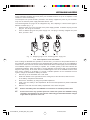
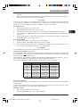
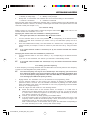
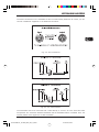
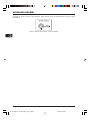
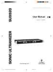
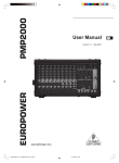
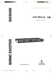
Version 1.0
August 2006
ULTRALINK
UL2000B
User’s manual
DATA-MANFULL_UL2000B_ENG_Rev_A.pmd 1
04.09.2006, 09:36
ULTRALINK UL2000B
IMPORTANT SAFETY INSTRUCTIONS
CAUTION:
To reduce the risk of electric shock, do
not remove the top cover (or the rear
section). No user serviceable parts
inside; refer servicing to qualified
personnel.
WARNING:
To reduce the risk of fire or electric
shock, do not expose this appliance
to rain and moisture. The apparatus
should not be exposed to dripping or
splashing and no objects filled with
liquids, such as vases, should be
placed on the apparatus.
This symbol, wherever it appears,
alerts you to the presence of
uninsulated dangerous voltage inside
the enclosure—voltage that may be
sufficient to constitute a risk of shock.
This symbol, wherever it appears,
alerts you to important operating and
maintenance instructions in the
accompanying literature. Please read
the manual.
DETAILED SAFETY INSTRUCTIONS:
1) Read these instructions.
2) Keep these instructions.
3) Heed all warnings.
4) Follow all instructions.
5) Do not use this apparatus near water.
6) Clean only with dry cloth.
7) Do not block any ventilation openings. Install in accordance with the manufacturer’s instructions.
8) Do not install near any heat sources such as radiators, heat registers, stoves, or other apparatus (including
amplifiers) that produce heat.
9) Protect the power cord from being walked on or pinched particularly at plugs, convenience receptacles,
and the point where they exit from the apparatus.
10) Only use attachments/accessories specified by the manufacturer.
11) Use only with the cart, stand, tripod, bracket, or table specified by the manufacturer, or sold with the
apparatus. When a cart is used, use caution when moving the cart/apparatus combination to avoid injury
from tipping over.
12) Unplug this apparatus during lightning storms or when unused for long periods of time.
13) Refer all servicing to qualified service personnel. Servicing is required when the apparatus has been
damaged in any way, such as power supply cord or plug is damaged, liquid has been spilled or objects have
fallen into the apparatus, the apparatus has been exposed to rain or moisture, does not operate normally, or
has been dropped.
14) CAUTION - These service instructions are for use by qualified service personnel only. To reduce the risk
of electric shock do not perform any servicing other than that contained in the operation instructions unless
you are qualified to do so.
SAFETY INSTRUCTIONS FOR THE WALL POWER SUPPLY:
1) The power supply can only be operated in the temperature range between 0° - 40°C (32 - 104 F).
2) Never use the unit near water or moisture.
3) Do not use the unit outdoors.
4) Do not expose the unit to high temperatures or direct sunlight for prolonged time.
5) Assure sufficient ventilation to avoid overheating.
6) Should the wall power unit get damaged or become defective, do not attempt to open it yourself. Repairs
should only be done by qualified personnel.
2
DATA-MANFULL_UL2000B_ENG_Rev_A.pmd 2
04.09.2006, 09:36
ULTRALINK UL2000B
TABLE OF CONTENTS
1. INTRODUCTION ......................................................................................................... 4
1.1 Before you get started ..........................................................................................................
1.1.1 Shipment ......................................................................................................................
1.1.2 Registration .................................................................................................................
1.1.3 Initial operation of the receiver ...................................................................................
1.1.4 Initial operation of the transmitter ................................................................................
1.1.5 Online-Registration ......................................................................................................
4
4
4
5
5
6
2. ULR2000 RECEIVER .................................................................................................. 6
2.1 Control elements and connections ........................................................................................ 6
2.1.1 The front ...................................................................................................................... 6
2.1.2 Display ......................................................................................................................... 7
2.1.3 The back ...................................................................................................................... 8
2.2 Menu items in detail ............................................................................................................... 8
2.2.1 TUNE ............................................................................................................................ 9
2.2.2 SCAN ........................................................................................................................... 9
2.2.3 SQUELCH .................................................................................................................... 9
2.2.4 AUTO MUTE ............................................................................................................... 10
2.2.5 DISPLAY .................................................................................................................... 10
2.2.6 LOCK .......................................................................................................................... 11
2.2.7 PRESET ....................................................................................................................... 11
3. ULB2000 TRANSMITTER ......................................................................................... 12
3.1 Control elements ..................................................................................................................
3.2 Operating the Transmitter ...................................................................................................
3.2.1 Turning the transmitter on .........................................................................................
3.2.2 Channel setting ..........................................................................................................
3.2.3 Setting your own frequency ....................................................................................
3.2.4 Preset ........................................................................................................................
3.2.5 Mic Gain .....................................................................................................................
3.2.6 Auto Mute ..................................................................................................................
3.2.7 Turning the transmitter off ........................................................................................
3.3 Status query ........................................................................................................................
3.3.1 Battery condition and transmission channel ............................................................
3.3.2 Transmission frequency ...........................................................................................
3.3.3 Preset ........................................................................................................................
3.3.4 Mic Gain .....................................................................................................................
3.3.5 Auto Mute ..................................................................................................................
3.5 ULB2000 level setting ..........................................................................................................
12
12
12
13
13
14
15
16
17
17
17
17
17
17
18
18
4. APPLICATION EXAMPLE ......................................................................................... 18
5. INSTALLATION ......................................................................................................... 19
5.1 Operating information ..........................................................................................................
5.1.1 Attach the transmitter ...............................................................................................
5.1.2 General information ...................................................................................................
5.2 Installation in a rack .............................................................................................................
5.3 Audio connections ..............................................................................................................
19
19
19
19
21
6. SPECIFICATIONS ..................................................................................................... 23
6.1 ULR2000 receiver ............................................................................................................... 23
6.2 ULB2000 transmitter ............................................................................................................ 24
FEDERAL COMMUNICATIONS COMMISSION COMPLIANCE INFORMATION ............. 25
MICROPHONE QUICK START GUIDE ........................................................................... 26
3
DATA-MANFULL_UL2000B_ENG_Rev_A.pmd 3
04.09.2006, 09:36
ULTRALINK UL2000B
1. INTRODUCTION
Thank you very much for expressing your confidence in the ULTRALINK Series by purchasing this
unit. With the UL2000B from BEHRINGER, you have acquired a modern, high-performance wireless
transmission system.
Due to its amazing set of features, you can use the ULB2000 in any situation that requires the
highest quality in sound and freedom of movement for live concerts, events and television productions.
Depending on your local wireless transmission regulations, you can use up to 20 systems
simultaneously.
The ULR2000 receiver uses two complete receiver channels, which are automatically tuned to the
same frequency. This function requires no attention from the user. This so-called True Diversity
technology enables outstanding disturbance-free signal transmission. This way, you can profit from
the greatest freedom of movement and can fully concentrate on what’s essential: your music.
The IRC compander system guarantees an extremely wide transmission dynamic range. Since
vocals benefit from this characteristic most, the UL2000B is ideal for such applications.
The headset is holds a high-grade Panasonic® capsule with a cardioid polar pattern. Therefore, it
primarily picks up the sound from the front and less from the sides. The sound that reaches the
backside of the microphone is suppressed as much as possible, allowing it to be less susceptible to
feedback in live situations.
The ULTRALINK Series equipment features 3 factory presets, each with 8 permanent, interferencefree channels. This allows you to use several systems in parallel without them influencing one
another. Additionally, you have the option of storing 8 of your own frequencies in a user preset, thus
individually addressing your own needs.
Determining which microphone is assigned to which receiver is done either by observing the
transmission channel in the display or by comparing the transmission frequency. In addition, the
ULTRALINK equipment from BEHRINGER leaves you the option to color-code your gear for easy
identification.
Beyond that, both units feature other useful functions, such as Scan and Auto Mute. This way, no
wishes are left open during practice or in live situations.
The following instructions are intended to familiarize you with the unit’s controls, so that
you can learn all of its functions. After having thoroughly read these instructions, store
them in a safe place for future reference.
1.1 Before you get started
1.1.1 Shipment
The UL2000B was carefully packed at the factory to assure secure transportation. Should the
condition of the cardboard box suggest that damage may have taken place, please inspect the unit
immediately and look for physical indications of damage.
Damaged units should NEVER be sent directly to us. Please inform the dealer from
whom you acquired the unit immediately as well as the transportation company from
which you took delivery of the unit. Otherwise, all claims for replacement/repair may be
rendered invalid.
Always use the original packaging to avoid damage due to storage or shipment.
Never leave children unsupervised with the unit or its packaging.
Please dispose of all packaging materials in an environmentally friendly manner.
1.1.2 Registration
Before powering up the unit for the first time, you have to register it with your local postal/
telecommunication authority! Additional information is available there.
4
DATA-MANFULL_UL2000B_ENG_Rev_A.pmd 4
1. INTRODUCTION
04.09.2006, 09:36
ULTRALINK UL2000B
1.1.3 Initial operation of the receiver
Assure adequate ventilation and never place your ULR2000 receiver on top of an amplifier or near
radiators to avoid overheating.
The wall power unit (model: E-SPS1) included in the delivery supplies the power to your ULR2000.
Only use the external power supply delivered with the unit!
The interchangeable AC plugs can be swapped at any time, adapting to various socket types in
different countries (Fig. 1.1).
1.
Keep the button (A) on the front side of the power supply pressed to release the plug. Pull the
plug out and let go of the button.
2.
Insert a different plug into the power supply unit. The plug is securely snapped into place
when you hear a click.
Fig. 1.1: Swapping plugs on the switching power supply unit
1.1.4 Initial operation of the transmitter
Prior to taking the ULB2000 into operation for the first time, you need to fit the provided antenna on
the transmitter. Connect the antenna to the designated plug located on the top of the ULB2000 by
means of the screw connector. Ensure that the antenna has been screwed tightly onto the transmitter.
The ULB2000 requires a 9-V battery to operate. The constant glowing of the LED indicates the
operational readiness. When the battery is nearly depleted, the STATUS LED on the transmitter
begins to flash quickly. At the same time, an inaudible signal is sent to the ULR2000 receiver which
then shows "LowBat" on its display. To ensure a reliable operation of the transmitter-receiver
system, change the transmitter's battery as follows:
1.
Hold the top of the transmitter with a free hand.
2.
Press both latches to the right and left of the casing and, at the same time, slide the cover
of the battery compartment downwards.
3.
Remove the old battery by using the provided implement.
4.
Insert a new 9-V battery in the compartment. Be sure that the implement is placed underneath
the battery.
5.
Slide the cover back onto the battery compartment until it locks into place.
Remove the battery when the ULB2000 is not used for an extended period of time.
Please ensure that only qualified personnel install and operate the ULB2000. During
installation and operation, the user must be sufficiently grounded. Electrostatic charges
might affect the operation of the unit.
1. INTRODUCTION
DATA-MANFULL_UL2000B_ENG_Rev_A.pmd 5
5
04.09.2006, 09:36
ULTRALINK UL2000B
1.1.5 Online-Registration
Please do remember to register your new BEHRINGER equipment right after your purchase by visiting
www.behringer.com (alternatively www.behringer.de) and kindly read the terms and conditions of our
warranty carefully.
Should your BEHRINGER product malfunction, our goal is to have it repaired as quickly as possible.
To arrange for warranty service, please contact the retailer from whom the equipment was purchased.
Should your BEHRINGER dealer not be located in your vicinity, you may directly contact one of our
subsidiaries. Corresponding contact information is included in the original equipment packaging
(Global Contact Information/European Contact Information). Should your country not be listed, please
contact the distributor nearest you. A list of distributors can be found in the support area of our website
(www.behringer.com).
Registering your purchase and equipment with us helps us process your repair claims quicker and more
efficiently.
Thank you for your cooperation!
2. ULR2000 RECEIVER
2.1 Control elements and connections
In this chapter, different control elements of your ULR2000 will be described, explained in detail,
and you will get useful information on how to use them.
2.1.1 The front
Fig. 2.1: ULR2000’s front side
POWER
To power the ULR2000 on or off, keep the POWER button pressed for at least 2 seconds. To
disconnect the unit from the mains, please unplug the power supply. Make sure the wall power
supply is easily accessible whenever you use the ULR2000. If you mount it in a rack, make sure
that you can easily unplug the wall power supply or an all-pole disconnect switch.
Please keep in mind: The POWER switch does not entirely separate the unit from the
mains. Please disconnect the power cord from the mains if you won’t be using the unit
for a while.
VOLUME
The output signal level of the receiver can be set using the VOLUME control. If you run the
ULR2000 in a setup with balanced connections, a maximum signal level of 12.5 dBu is
possible; in setups with unbalanced connections, the maximum signal level is 6.5 dBu.
We would like to point out that high volume levels may cause distortion and high signal
levels in other equipment to which your ULR2000 is connected (e.g. mixing console or
headphones). High volume levels may damage your hearing and/or your headphones/
speakers. Please turn the VOLUME control all the way to the left (very low output signal)
before turning the ULR2000 on. Always make sure that an appropriate volume is set.
6
DATA-MANFULL_UL2000B_ENG_Rev_A.pmd 6
2. ULR2000 RECEIVER
04.09.2006, 09:36
ULTRALINK UL2000B
DISPLAY
All important parameters are shown in the display (ch. 2.1.2).
SET
The SET button has 2 functions:
Press this button to bring up the menu.
To confirm the values you set in the menu, press the SET button.
UP and
DOWN
These two buttons let you navigate the menu and change the values shown in the display (e.g.
frequency, channel number, preset number).
If the ULR2000 is in the basic setting (menu not selected), pressing the
UP and the
DOWN
buttons changes the transmission channel within the selected preset.
The
UP and
DOWN buttons have a repeat functionality with many function (i.e. the action
is carried out perpetually if the button is kept pressed; for example, setting a carrier frequency
can be simplified this way).
COLOR CODE
Each BEHRINGER ULTRALINK transmitter can be color-coded using a color ring; this way you
can easily differentiate between multiple transmitters (set to different frequencies). To easily
match a transmitter to a receiver, you can also attach color-coded strips to each receiver.
ANTENNA
Two bar antennae can be connected to the ANTENNA 1 and ANTENNA 2 connectors.
2.1.2 Display
Fig. 2.2: Closeup of the ULR2000 display
(antenna symbol)
These two antenna symbols indicate which antenna signal is currently being processed. The
left symbol lights up when the signal from the left-hand antenna (ANTENNA 1) is stronger, and
the right symbol shows that the signal from the right-hand antenna (ANTENNA 2) is being
processed.
RF LEVEL
The 8-level RF LEVEL display shows the reception strength of the carrier frequency (Radio
Frequency) on the ULR2000.
If not a single bar is shown, the carrier frequency is not being received. Bad reception is
indicated with 1 - 3 bars; signal noise may be somewhat higher in this case. The more bars are
shown, the better the reception of the transmitter carrier frequency on the ULR2000.
AF
Similar to a distortion gauge on a mixer or an amplifier, the 8-level AF indicator shows how
loud the demodulated audio signal (Audio Frequency) is.
If the signal has no amplitude or if the amplitude is low, no bars are shown. The maximum
undistorted AF-level is received when 7 bars (and not 8!) light up.
Only when the audio signal is overdriving or when no RF signal can be received (the
receiver creates too much noise), 8 bars are shown in the LCD.
2. ULR2000 RECEIVER
DATA-MANFULL_UL2000B_ENG_Rev_A.pmd 7
7
04.09.2006, 09:36
ULTRALINK UL2000B
Alphanumeric display
All the values and letters relevant to the operation of your ULR2000 are shown in the 6-digit
alphanumeric display: for example, channel number, channel color, frequency and menu
items.
CHANNEL
If the ULR2000 is in the basic setting (menu not selected), pressing the
UP and
DOWN
buttons changes the transmission channel within the selected preset.
If CHANNEL is lit, the individual channel numbers are shown (CHAN1, CHAN2, ...).
Also, when storing a user-selected frequency in the user preset, a channel number is entered.
FREQ MHz
If FREQ MHz lights up, changing the transmission channel using the
buttons also displays the frequency of the selected channel.
UP and
DOWN
If neither CHANNEL nor FREQ MHz are lit, the display is indicating the channel color
(BLUE, RED, ...) of the set channel. When storing a user-selected frequency in the user
preset, you will be asked to enter a channel color.
MUTE
MUTE indicates that the ULR2000 ’s output is being muted.
If the received and demodulated AF starts getting weaker, the noise increases; the signal-tonoise ratio gets smaller.
The SQUELCH menu item lets you enter a threshold value (in dB) for the signal-to-noise ratio.
If this ratio gets smaller than the threshold value, the receiver automatically mutes the signal
(ch. 2.2.3).
2.1.3 The back
Fig. 2.3: ULR2000 ’s back
The power is supplied via a 12 V connector. A matching cable is included in the delivery.
If the power supply is interrupted (e.g. by removing the wall power supply), please wait
at least 10 seconds before restoring the power supply again. This avoids causing
possible damage to the unit.
Balanced XLR output.
Balanced TRS output.
GND
The unit can be earthed. Attach an earthing cable to the GND screw.
SERIAL NUMBER
2.2 Menu items in detail
Briefly pressing the SET button gets you into the ULR2000’s menu. There you have many different
options to individually configure the receiver.
By using the
UP and
DOWN buttons you can select various menu items (e.g. TUNE, SCAN).
Pressing the SET button once gets you into the respective submenu (e.g. submenu TUNE). By
pressing the
UP and
DOWN buttons, you can select different settings in the submenu. Pressing
the SET button again confirms your selection.
8
DATA-MANFULL_UL2000B_ENG_Rev_A.pmd 8
2. ULR2000 RECEIVER
04.09.2006, 09:36
ULTRALINK UL2000B
If menu is selected and you make no parameter changes for a while, the unit automatically
exits the menu.
2.2.1 TUNE
A freely selectable carrier frequency in the range between 798.100 - 805.900 MHz can be set in the
TUNE menu. This frequency is then stored in one of the 8 storage slots in the user preset (Preset 1).
Depending on the basic settings of your ULR2000 (ch. 2.2.5), when selecting a storage slot you will
be prompted to enter a channel number or a channel color.
The carrier frequency can only be set in 25-kHz increments.
1.
Press the SET button to get to the menu. TUNE is the first menu item.
2.
Press the SET button again to get to the TUNE submenu. The frequency value blinks.
3.
Using the
UP and
increments.
4.
If a valid frequency value is set, press the SET button again. In the display, you are asked to
enter where you want to save your settings. Depending on the basic settings (ch. 2.2.5), the
ULR2000 asks you to enter a channel color (BLUE, RED, ...) or a channel number (CHAN1,
CHAN2, ...).
5.
A storage location can be selected by pressing the
6.
Press the SET button again to store your frequency at the location you selected. T
h
e
procedure is now over, and the basic settings are shown in the display again (channel number,
channel frequency or channel color).
DOWN buttons, the “Frequency” parameter can be modified in 25-kHz
UP or
DOWN buttons.
A user-selected frequency is always stored in the user preset (Preset 1)! If necessary,
the unit automatically switches to this preset.
2.2.2 SCAN
Similar to a tuner in a radio or a TV set, the ULR2000 automatically searches for a transmitter when
in SCAN mode. For it to work, the transmitter (e.g. the ULB2000) must be turned on!
1.
Press the SET button to get to the menu.
2.
Press the
3.
Press the SET button again to get to the SCAN submenu. The display shows the current
frequency.
4.
Either press
UP or
DOWN. This way, you determine if the scan is going to be performed
in the ascending or descending direction. The scan begins.
5.
As soon as the ULR2000 recognizes the transmitter frequency, it is shown in the display.
If this frequency is not the frequency you were looking for, you can start a new scan by pressing
t
h
e
UP or
DOWN buttons.
6.
If the receiver found the correct frequency, press the SET button again. In the display, you are
asked to enter where you want to save your settings. Depending on the basic settings, the
ULR2000 asks you to enter a channel color (BLUE, RED, ...) or a channel number (CHAN1,
CHAN2, ...).
UP button once to get to SCAN.
7.
A storage location can be selected by pressing the
8.
Press the SET button again to store your frequency at the location you selected. T
procedure is now over, and the basic settings are shown in the display again.
UP or
DOWN buttons.
h
e
A scan can also be halted manually (e.g. in case the receiver is unable to locate a
transmitter). To do this, press the SET button; the scan is immediately interrupted. Now,
you can either start another scan (see lines 4 and 5), or the frequency shown can be
stored (see lines 6, 7 and 8).
2.2.3 SQUELCH
With wireless signal transmission, restricted reception conditions may cause the transmission of
additional noise and interference. The Squelch function lets you adjust if the ULR2000 is muted
under such conditions. You can also enter the noise level that will trigger the mute function:
2. ULR2000 RECEIVER
DATA-MANFULL_UL2000B_ENG_Rev_A.pmd 9
9
04.09.2006, 09:36
ULTRALINK UL2000B
0 dB:
the receiver is not muted
low dB value:
the receiver is muted only if substantial noise is transmitted with the signal
high dB value:
the receiver is muted even if the noise floor is low
Setting a Squelch value
1.
Press the SET button to get to the menu.
2.
Press the
3.
Press the SET button again to get to the SQELCH submenu. The display shows the current dB
value.
UP button twice to get to SQELCH.
4.
Press the
UP or the
DOWN buttons to adjust the dB value of the noise limiter. Values
between 0 and 40 dB can be selected in 5-dB increments.
If a squelch value of 0 dB is set, the receiver will not mute the signal no matter how
noise-saturated the incoming signal is.
5.
Press the SET button to store your dB value. The procedure is now over, and the basic settings
are shown in the display again.
2.2.4 AUTO MUTE
If the transmitter is turned on, off, or is switched to another channel without first muting the receiver,
or if the transmission drops out due to weak batteries, audible noise will result. Even if the noise
limiter is enabled on the receiver (ch. 2.2.3), it still requires some time to react, and such noise can
not be suppressed safely.
To bridge this latency time, the ULR2000 offers a practical Auto Mute function:
When the ULB2000 is being turned off, when you are switching channels or during low-battery
indication, an inaudible send signal is being transmitted.
The ULR2000 recognizes this signal and automatically mutes the output before the transmitter
is actually turned off, switched to another channel or before it powers down on its own due to
battery charge being too low.
For the Auto Mute function to work, it has to be activated on both the transmitter and the
receiver!
Activating/deactivating the Auto Mute function
1.
Press the SET button to get to the menu.
2.
Press the
3.
Press the SET button again to get to the A.MUTE submenu. Depending on the current setting,
the display shows ON or AMTOFF.
UP button three times to get to A.MUTE.
4.
Press the
5.
Press the SET button to save your settings. The procedure is now over, and the basic settings
are shown in the display again.
UP or the
DOWN buttons to turn the auto mute function on or off.
2.2.5 DISPLAY
When you power the ULR2000 on, its basic settings are loaded. That means that the channel you
selected last is shown; you can change this channel immediately without going to menu by using
the
UP
and
DOWN buttons.
There are 3 different ways to show the selected channel in the display. You can decide for yourself
which representation is the most appropriate for your applications:
The exact channel carrier frequency is shown (FREQU).
The channel number is shown in the display (CHANNL).
The color assigned to the channel is shown in the display (COLOR).
Changing the ULR2000’s basic settings
1.
Press the SET button to get to the menu.
2.
Press the
3.
Press the SET button again to get to the DISPL submenu. The display shows the current basic
parameter.
DOWN button three times to get to DISPL.
10
DATA-MANFULL_UL2000B_ENG_Rev_A.pmd 10
2. ULR2000 RECEIVER
04.09.2006, 09:36
ULTRALINK UL2000B
4.
Press the
COLOR).
UP and
DOWN buttons to set one of the 3 parameters (FREQU, CHANNL or
5.
Press the SET button to store the parameter for the basic setting. The procedure is now over,
and the new basic setting is shown in the display.
2.2.6 LOCK
To prevent your settings from accidentally being changed, you can activate the keylock function
(LOCK). With the exception of the SET button, all other buttons (including the Power button) are
locked. If one of those buttons is pressed, “LOCKED” is shown in the display.
Activating LOCK
1.
Press the SET button to get to the menu.
2.
Press the
3.
Press the SET button again to get to the LOCK submenu. The display shows LOCOFF.
DOWN button twice to get to LOCK.
4.
Press the
LOC ON.
5.
Press the SET button to activate the keylock function. The procedure is now over, and the basic
settings are shown in the display again.
UP and
DOWN buttons once to activate the keylock function. The display shows
Deactivating LOCK
1.
Press the SET button. LOC ON is shown in the display.
2.
Press the
3.
Press the SET button confirm, hence deactivating the keylock function. The procedure is now
over, and the basic settings are shown in the display again.
UP or
DOWN button once to select LOCOFF.
2.2.7 PRESET
The ULR2000 lets you work with 4 presets, each with 8 channels.
Factory presets (Presets 2, 3 and 4)
In the ULR2000, there are 3 factory presets (each with 8 interference-free channels). That means that
all 8 channels of one preset can run simultaneously with 8 different transmitters and receivers
without causing mutual interference.
The channels in the 3 factory presets are all assigned to different frequencies. This way, you can
always select a frequency range that assures the best signal transmission.
The following table shows which frequencies are stored in the factory presets.
CHANNEL
PRESET 2
PRESET 3
PRESET 4
1
798,700 MHz
798,400 MHz
798,100 MHz
2
799,950 MHz
798,950 MHz
798,650 MHz
3
800,650 MHz
799,800 MHz
799,500 MHz
4
801,050 MHz
801,450 MHz
801,150 MHz
5
802,850 MHz
803,250 MHz
802,950 MHz
6
804,500 MHz
803,650 MHz
803,350 MHz
7
805,350 MHz
804,350 MHz
804,050 MHz
8
805,900 MHz
805,600 MHz
805,300 MHz
Table 2.1: Factory preset frequencies (presets 2,3 and 4)
User preset (Preset 1)
Preset 1 is meant for the user. Frequencies of your own choice can be stored in the 8 storage slots
of this preset.
If you have not stored any of your own frequencies, the frequencies stored in the user preset
(Preset 1) are identical to the frequencies stored in Preset 3.
Loading a preset
1.
Press the SET button to get to the menu.
2.
Press the
DOWN button once to get to PRESET.
2. ULR2000 RECEIVER
DATA-MANFULL_UL2000B_ENG_Rev_A.pmd 11
11
04.09.2006, 09:36
ULTRALINK UL2000B
3.
Press the SET button again to get to the PRESET submenu. The display shows the currently
active preset.
4.
Press the
3 or 4).
5.
Press the SET button to load up the preset you selected. The procedure is now over, and the
basic setting is shown in the display again.
UP and
DOWN buttons to select the desired preset. The display shows PSET 1 (2,
3. ULB2000 TRANSMITTER
3.1 Control elements
In this chapter, different control elements of your ULB2000 will be described, explained in detail,
and you will get useful information on how to use them.
Fig. 3.1: Controls of the ULB2000
POWER
To power the hand-held transmitter on or off, keep the POWER button pressed for at least 2
seconds. Briefly pressing the POWER button confirms your choices when entering values
(refers to later chapters). Additionally, you can check the current transmitter settings (selected
channel and battery condition).
MUTE switch
Engaging the MUTE switch mutes the microphone. Additionally, the ULB2000 can be switched
to programming mode by selecting the digits 9 or 0; or, you can get a readout of a specific unit
setting.
SELECTION SWITCH
Using a screwdriver, you can select different values on the SELECTION SWITCH. For example,
you can select a channel number and the frequency.
STATUS LED
Through repeated blinking, the status LED gives the account of the current settings for all
parameters. We differentiate between 3 different blinking tempos:
The LED flashes slowly when exiting the programming mode, for example.
To give the account of the channel number or individual frequency values, the LED
blinks with medium tempo.
Rapid blinking indicates an error, for example an empty battery or a faulty entry.
The costant glowing of the LED indicates the operational readiness of the transmitter.
The SERIAL NUMBER is located on the transmitter battery compartment. To get to the serial
number, please open the battery compartment (see ch. 1.1.4).
3.2 Operating the Transmitter
A brief overview with the graphic representation on operating the transmitter is found on the last
page of this user manual (QUICK REFERENCE GUIDE).
3.2.1 Turning the transmitter on
1.
Press the transmitter’s POWER button for 2 seconds.
12
DATA-MANFULL_UL2000B_ENG_Rev_A.pmd 12
3. ULB2000 TRANSMITTER
04.09.2006, 09:36
ULTRALINK UL2000B
2.
3.
A blink code indicates the charge level of the battery:
1 = Battery is nearly empty . . . 5 = Battery is fully charged
Shortly after, a second blink code indicates the current channel setting for the transmitter:
1 = Channel 1 is selected
...
8 = Channel 8 is selected
When the blink codes have indicated the operating state, a constant glowing of the LED indicates the
operational readiness. However, the battery is discharged and needs to be replaced when the LED
continues to flash (see Chapter 1.1.4).
3.2.2 Channel setting
Within a preset, you can easily select a channel by using the select switch
relevant whether the transmitter is on or off.
. In this case, it is not
Changing the channel when the transmitter is already powered on
During this procedure, the transmitter may not be set to mute!
1.
Turn the selection switch to one of the positions 1 - 8, corresponding to the desired channel
number. If a valid value is selected (i.e. neither 9 nor 0), the LED blinks quickly once as a
confirmation.
2.
Press the POWER button briefly. The LED flashes at a medium rate, corresponding to the
channel number (for example, 5 times for channel 5) that has been set by using the select
switch.
If an invalid channel number is selected (0 or 9), the channel selected last remains
selected.
Changing the channel when the transmitter is powered off
1.
Turn the selection switch to one of the values (1 - 8), corresponding to the desired channel
number.
2.
If you turn on the transmitter, the channel you selected is automatically loaded.
If an invalid channel number was selected (0 or 9), the channel selected last remains
selected.
3.2.3 Setting your own frequency
A carrier frequency in the range between 798.1 and 805.9 MHz can be freely selected. This frequency
is stored in a self-assignable user preset (Preset 1).
The carrier frequency can only be set in 25-kHz steps. The frequency you select has to
be a multiple of 25 kHz. If you select a frequency that is not a multiple of 25 kHz or does
not lie in the frequency range between 798.1 and 805.9 MHz, the ULB2000 gives off an
error message (the LED blinks quickly 5 times).
1.
Engage MUTE. The transmitter can now be switched to the programming mode.
2.
Turn the selection switch to 9 and confirm your selection by keeping the POWER button
pressed for about 2 seconds. The LED indicates confirmation by blinking once with medium
tempo and blinking once slowly. The transmitter is now in the programming mode and awaits
the entry of a 6-digit frequency.
3.
Enter all 6 digits one after another in the following fashion:
Select the desired value on the selection switch, for example 4. If a valid value is
selected, the LED blinks quickly once as a confirmation. This way, you can be sure that
a correct value is entered (in regard to the frequency range and divisibility by 25 kHz)
even before confirming your selection.
Confirm your selection by briefly pressing the POWER button.
If the end frequency value you entered is valid, the LED blinks quickly once more. If the
frequency value is invalid, the LED blinks quickly 5 times, and the unit is no longer in the
programming mode. In this case, start anew with step 2.
After a brief interruption, a second blink code is given: the LED blinks corresponding to
the value selected (in this case, 4 times) with medium tempo.
3. ULB2000 TRANSMITTER
DATA-MANFULL_UL2000B_ENG_Rev_A.pmd 13
13
04.09.2006, 09:36
ULTRALINK UL2000B
The value 0 is indicated by a very short blink of the LED, and you will easily tell a
0 from a 1.
If no entry is made for more than 5 seconds (either on the selection switch or by
pressing the POWER button), the LED blinks quickly 5 times, and the programming
mode is aborted.
After entering the 6 digits for the frequency value, enter another value to indicate the channel
number under which the frequency will be stored.
4.
Select a desired channel number on the selection switch, for example channel 2 (possible
values: 1 - 8). If a valid value is selected, the LED blinks quickly once to confirm. This way, you
can be sure that a correct channel number is being entered even before confirming your
selection.
5.
Confirm your selection by briefly pressing the POWER button.
6.
When a valid value is selected, the LED blinks briefly again. When an invalid value is
selected, the LED blinks quickly 5 times and the unit is no longer in the programming mode.
In this case, start anew with step 2.
After a brief interruption, a second blink code is given: the LED blinks corresponding to the
value selected (in this case, 2 times) with medium tempo.
7.
After a second blink pause, an additional blink code is given as a confirmation:
A successfully stored frequency is signaled with 2 slow blinks. The transmitter leaves the
programming mode.
If the LED blinks quickly 5 times, the frequency was not stored. In this case, start anew with
step 2.
If no entry is made for more than 5 seconds (either on the selection switch or by
pressing the POWER button), the LED blinks quickly 5 times, and the programming
mode is aborted.
8.
Disengage the MUTE switch.
A user-assigned frequency is automatically stored in the user preset (Preset 1)!
3.2.4 Preset
The ULB2000 lets you work with 4 presets, each with 8 channels.
Factory presets (Presets 2, 3 and 4)
In the ULB2000, there are 3 factory presets (each with 8 interference-free channels). That means that
all 8 channels of one preset can run simultaneously with 8 different transmitters and receivers
without causing interference to one another.
The channels in the 3 factory presets are all assigned to different frequencies. This way, you can
always select a frequency range that assures the best signal transmission.
The following table shows which frequencies are stored in the factory presets.
CHANNEL
PRESET 2
PRESET 3
PRESET 4
1
798,700 MHz
798,400 MHz
798,100 MHz
2
799,950 MHz
798,950 MHz
798,650 MHz
3
800,650 MHz
799,800 MHz
799,500 MHz
4
801,050 MHz
801,450 MHz
801,150 MHz
5
802,850 MHz
803,250 MHz
802,950 MHz
6
804,500 MHz
803,650 MHz
803,350 MHz
7
805,350 MHz
804,350 MHz
804,050 MHz
8
805,900 MHz
805,600 MHz
805,300 MHz
Table 3.1: Factory preset frequencies (presets 2,3 and 4)
User preset (Preset 1)
Preset 1 is meant for the user. Frequencies of your own choice can be stored in the 8 storage slots
of this preset.
14
DATA-MANFULL_UL2000B_ENG_Rev_A.pmd 14
3. ULB2000 TRANSMITTER
04.09.2006, 09:36
ULTRALINK UL2000B
If you have not stored any of your own frequencies, the frequencies stored in the user preset
(Preset 1) are identical to the frequencies stored in Preset 3.
Loading a preset
1.
Engage MUTE. The transmitter can now be switched into the programming mode.
2.
Turn the selection switch to 0 and confirm your selection by keeping the POWER button
pressed for 2 seconds. As a confirmation, the LED blinks slowly once and then once again with
medium tempo. The transmitter is now in the programming mode and waits for you to enter a
one-digit number.
3.
Select the desired preset number on the selection switch, e.g. 3 (possible choices: 1 - 4). If a
valid selection is made, the LED blinks once quickly to confirm your selection. This way, you
can be sure that a correct value is entered (in regard to the selection of presets, Mic Gain and
Auto Mute) even before confirming your selection.
Selecting 5 or 6 changes the Mic Gain setting (ch. 3.2.5). Selecting 7 or 8 changes the
Auto Mute settings (ch. 3.2.6). Values 9 and 0 are invalid.
4.
Confirm your selection by briefly pressing the POWER button.
5.
If the selection you made is valid, the LED blinks quickly once again. An invalid selection is
indicated with 5 quick blinks, and the unit is immediately no longer in the programming mode.
In this case, start anew with step 2.
After a brief break, a second blink code is given: The LED blinks according to the value
selected (for example, in this case 3 times) with medium tempo.
If no entry is made for more than 5 seconds (either on the selection switch or by
pressing the POWER button), the LED blinks quickly 5 times, and the programming
mode is aborted.
6.
After a second brief blink break, an additional blink code is given as a confirmation:
7.
Successful loading of a preset is signaled with two slow blinks. The unit leaves the
programming mode.
If the preset could not be loaded, the LED blinks quickly 5 times. In this case, start anew
with step 2.
After setting the desired preset, disengage the MUTE switch.
3.2.5 Mic Gain
You have the option to adjust the ULB2000 to the level of the signal being transmitted. If you talk
very softly into the microphone, we recommend the “High Gain” setting; if the sound is loud, select
“Low Gain.” This way, optimal transmitter drive is achieved.
1.
Engage MUTE. The transmitter can now be switched into the programming mode.
2.
Turn the selection switch to 0 and confirm your selection by keeping the POWER button
pressed for 2 seconds. As a confirmation, the LED blinks slowly once and then once again with
medium tempo. The transmitter is now in the programming mode and waits for you to enter a
one-digit number.
3.
Select one of the following two digits on the selection switch:
Low Gain: select 5
High Gain: select 6
If a valid selection is made, the LED blinks quickly once to confirm your selection. This way,
you can be sure that a correct value is entered (in regard to preset, MicGain and Auto Mute
selection) even before confirming your selection.
Selecting the values 1 thru 4 changes the preset settings (ch. 3.2.4). Selecting 7 or 8
changes the Auto Mute settings (ch. 3.2.6). Values 9 and 0 are invalid.
4.
Confirm your selection by briefly pressing the POWER button.
5.
If the selection you made is valid, the LED blinks quickly once again. An invalid selection is
indicated with 5 quick blinks, and the unit is immediately no longer in the programming mode.
In this case, start anew with step 2.
After a brief break, a second blink code is given: The LED blinks according to the value
selected (for example, in this case 3 times) with medium tempo.
3. ULB2000 TRANSMITTER
DATA-MANFULL_UL2000B_ENG_Rev_A.pmd 15
15
04.09.2006, 09:36
ULTRALINK UL2000B
Low Gain: the LED blinks once with medium tempo.
High Gain: the LED blinks twice with medium tempo.
If no entry is made for more than 5 seconds (either on the selection switch or by
pressing the POWER button), the LED blinks quickly 5 times, and the programming
mode is aborted.
6.
After a second brief blink break, an additional blink code is given as a confirmation:
Successful loading of a preset is signaled with two slow blinks. The transmitter leaves the
programming mode.
If the setting for Mic Gain could not be stored, the LED blinks quickly 5 times. In this case,
start anew with step 2.
7.
Disengage MUTE.
3.2.6 Auto Mute
The receiver's incoming signal will contain audible noise and interference should the transmitter be
turned on, off or changed to another channel without having muted the microphone beforehand, or
if the transmission has been interrupted due to a drained battery in the transmitter. Even if the
squelch circuit is turned on at the receiver end, it still requires some time to react, and such noise
can not be suppressed safely.
To bridge this latency time, the ULB2000 offers a practical Auto Mute function:
When the ULB2000 is being turned off, when you are switching channels or during low-battery
indication, an inaudible send signal is being transmitted.
The ULR2000 recognizes this signal and automatically mutes the output before the transmitter
is actually turned off, switched to another channel or before it powers down on its own due to
battery charge being too low.
For the Auto Mute function to work, it has to be activated on both the transmitter and the
receiver!
Activating/deactivating the Auto Mute function
1.
Engage MUTE. The transmitter can now be switched into the programming mode.
2.
Turn the selection switch to 0 and confirm your selection by keeping the POWER switch
pressed for 2 seconds. As a confirmation, the LED blinks slowly once and then once again with
medium tempo. The transmitter is now in the programming mode and waits for you to enter a
one-digit number.
3.
Select one of the following two digits on the selection switch:
Activate Auto Mute: select 7
Deactivate Auto Mute: select 8
If a valid selection is made, the LED blinks quickly once to confirm your selection. This way,
you can be sure that a correct value is entered (in regard to preset, MicGain and Auto Mute
selection) even before confirming your selection.
Selecting the values 1 through 4 changes the preset settings (ch. 3.2.4). Selecting 5 or
6 changes the Mic Gain settings (ch. 3.2.5). Values 9 and 0 are invalid.
4.
Confirm your selection by briefly pressing the POWER button.
5.
If the selection you made is valid, the LED blinks quickly once again. An invalid selection is
indicated with 5 quick blinks, and the unit is immediately no longer in the programming mode.
In this case, start anew with step 2.
After a brief break, a second blink code is given:
Auto Mute activated: the LED blinks once at middle tempo.
Auto Mute engaged: the LED blinks twice at middle tempo.
If no entry is made for more than 5 seconds (either on the selection switch or by
pressing the POWER button), the LED blinks quickly 5 times, and the programming
mode is aborted.
16
DATA-MANFULL_UL2000B_ENG_Rev_A.pmd 16
3. ULB2000 TRANSMITTER
04.09.2006, 09:36
ULTRALINK UL2000B
6.
After a second brief blink break, an additional blink code is given as a confirmation:
Two slow blinks signal that the Auto Mute setting was changed. The transmitter leaves
the programming mode.
If the setting for Auto Mute could not be stored, the LED blinks quickly 5 times. In this
case, start anew with step 2.
7.
Disengage MUTE.
3.2.7 Turning the transmitter off
To turn off the transmitter, press the POWER button for 2 seconds. The LED flashes slowly to show
that the microphone is powering down.
The transmitter stores the frequency and the channel settings. These parameters are
restored to these same values the next time you turn the unit on.
3.3 Status query
During operation, the parameters "transmission channel", "battery condition", "transmission
frequency", "preset", "Mic Gain" and "Auto Mute" may need to be checked. The statuses can be
monitored without having to turn the transmitter off and back on.
3.3.1 Battery condition and transmission channel
1.
Turn the selection switch to 0. The position of the MUTE switch does not matter.
2.
Briefly press the POWER button.
3.
As is this case when turning the transmitter on, the blink codes flash at a medium rate
indicating the current status:
battery condition:
selcted channel:
1 = battery is nearly empty . . . 5 = battery is fully loaded
1 = channel 1 is selected. . .
8 = channel 8 is selected
If the receiver is not powered on, no status is indicated. Briefly pressing the POWER
button will neither turn the transmitter on nor off!
3.3.2 Transmission frequency
1.
Turn the selection switch to 9. The position of the MUTE switch is irrelevant.
2.
Briefly press the POWER button.
3.
Just like during programming, 6 blink medium-tempo codes indicate the individual digits that
make up the transmission frequency. Individual codes are separated from one another by brief
pauses.
The value 0 is signaled by a very short blink of the LED, and you will easily tell a
0 from a 1.
If the receiver is not powered on, no status is indicated. Briefly pressing the POWER
button will neither turn the transmitter on nor off!
3.3.3 Preset
1.
Make sure the transmitter is not muted (MUTE switch is set to OFF).
2.
Turn the selection switch to 1, 2, 3 or 4 and confirm your selection by briefly pressing the
POWER button.
3.
The LED indicates the preset number with the corresponding number of medium-tempo
blinks.
1.
Make sure the transmitter is not muted (MUTE switch is set to OFF).
2.
Turn the selection switch to 5 or 6 and confirm your selection by briefly pressing the POWER
button.
3.
The LED indicates the Mic Gain status with the corresponding number of medium-tempo
blinks:
3.3.4 Mic Gain
3. ULB2000 TRANSMITTER
DATA-MANFULL_UL2000B_ENG_Rev_A.pmd 17
17
04.09.2006, 09:36
ULTRALINK UL2000B
Low Gain: The LED blinks once with medium tempo.
High Gain: The LED blinks twice with medium tempo.
3.3.5 Auto Mute
1.
Make sure the transmitter is not muted (MUTE switch is set to OFF).
2.
Turn the selection switch to 7 or 8 and confirm your selection by briefly pressing the POWER
button.
3.
The LED indicates the Auto Mute status with the corresponding number of medium-tempo
blinks::
Auto Mute turned off: The LED blinks once with middle tempo.
Auto Mute turned on: The LED blinks twice with middle tempo.
3.5 ULB2000 level setting
To optimally set the level on your ULB2000, the High Gain or Low Gain setting has to be
set to the level of the signal being transmitted (ch. 3.2.5).
Adjust the gain control in the microphone channel of your mixing console so that the peak LED
lights up only occasionally or never at all. The EQ controls in the microphone channel should be set
to mid-travel position to start with. To get the sound you want, try changing the mic position relative
to the sound source or even move the microphone around in the recording room of your studio.
Adjusting the angle at which walls face the sound source can also be helpful. Only when the desired
basic sound has been achieved should you start to use equalizers and signal processors, if any at all
(remember: less is often more!)
4. APPLICATION EXAMPLE
Fig. 4.1 shows how easy it is to use the products from the BEHRINGER ULTRALINK Series.
Simply connect the balanced XLR output on the ULR2000 to the XLR input on your mixing console.
Of course, you can use the receiver’s TRS output to connect to the next device in the signal path.
Fig. 4.1: Wiring the ULR2000 receiver and the ULB2000 microphone
18
DATA-MANFULL_UL2000B_ENG_Rev_A.pmd 18
4. APPLICATION EXAMPLE
04.09.2006, 09:36
ULTRALINK UL2000B
5. INSTALLATION
5.1 Operating information
The quality of the wireless transmission depends on various local factors as well as the degree of
radiation and reception at transmitter and receiver, unlike the signal transmission over cable. To
minimize the risk of interference, take the following suggestions into account for a smooth operation
of the wireless system.
5.1.1 Attach the transmitter
For optimal operation of the transmitter, please observe the following when attaching the transmitter:
Use only the provided headset and ensure that the mini XLR-connector is fastened correctly.
Attach the transmitter to a belt by using the provided clip instead of simply placing it into a
pocket, for instance. The optimal freedom of movement is guaranteed by fastening the transmitter
to one's back or side.
Make sure the headset's cable is not wrapped around or comes into contact with the antenna; this
would result in an impairment of the transmission.
Avoid direct body contact with the antenna to attain a maximum range.
The headset's microphone capsule should be aligned towards the speaker at approximately 25 cm from the mouth. Ideally, the capsule should be kept off-centered to mouth and nose to
avoid the conveyance of breathing sounds.
5.1.2 General information
Always make sure that the devices are not operated in direct proximity of large metallic
surfaces (radiators, metal racks, reinforced concrete walls and similar).
The devices should always be at a height of at least 1 m (3 ft.) off the ground.
To assure good reception in many different positions, we advise against having the antennae
point at a 90-degree angle. Instead, antennae should be arranged at an angle of no more
than 40° in respect to one another.
To assure interference-free reception, ideally there should be no large objects placed between
the transmitter and the receiver. Not only the size but also the type of material play a role in
determining how strong signal interference will be!
Keep a minimum distance of 5 meters between transmitter and sender to avoid signal
overmodulation.
When using multiple transmitters, the distance between the transmitting units should be at least
20 cm to avoid crosstalk (i.e. intermodulation).
Replace used batteries ahead of time. A dropout would be unacceptable at a production,
hence, do not wait until the battery indicator warns you that the battery needs to be replaced.
Use the presets to guarantee an interference-free transmission of multiple transmitters and
receivers on up to 8 channels.
If you want to install your ULR2000 in a rack, please read the following chapter; there you can
find all the necessary information.
5.2 Installation in a rack
The ULR2000’s antennae are located in the front of the unit. This allows unproblematic installation
in a rack.
Each unit is delivered with a rack bracket and a connecting joint. This way, you can choose:
1.
If you wish to install only one unit in a rack, mount a rack bracket to one of the sides. In this
case, you will not need the included connecting joint. Now, install one side of the receiver into
the rack.
2.
To install 2 receivers in a rack, first connect the two receivers to one another at the bottom
using the connecting joint. Mount one rack bracket on the left side of one unit and one rack
bracket on the right side of the other unit. Now, both ULR2000s can be installed in a rack.
5. INSTALLATION
DATA-MANFULL_UL2000B_ENG_Rev_A.pmd 19
19
04.09.2006, 09:36
ULTRALINK UL2000B
To assure good reception, if possible, install the ULR2000 as high in a rack as possible,
so that the antennae protrude above the upper edge of the rack.
The ULR2000 requires one height unit (1 HE) for installation in a 19-inch rack. Please assure that
there are additional 10 cm (4 inches) of free space in the back for connecting cables.
For installation in a rack, use M6 machine screws and nuts.
Be sure that there is plenty of space around the unit for cooling and, to avoid overheating, please
do not place the ULR2000 on top of power amplifiers or other heat-emitting equipment.
If you wish to install more than 2 units in a rack, please make sure that there is enough space
between them (fig. 5.1). The lower unit’s antennae may not perturb against the upper unit’s antennae.
Otherwise, they could interfere with one another, causing a decrease in reception quality.
Fig. 5.1: Arrangement of multiple ULR2000s when installed on top of each other
20
DATA-MANFULL_UL2000B_ENG_Rev_A.pmd 20
5. INSTALLATION
04.09.2006, 09:36
ULTRALINK UL2000B
5.3 Audio connections
The audio connections on the ULR2000 are laid out electronically balanced. Of course, you can
connect unbalanced equipment to the balanced connectors.
Fig. 5.2: XLR connections
Fig. 5.3: 1/4" TS connector
Fig. 5.4: 1/4" TRS connector
The transmitter cannot be connected with a cable directly to a mixer, as is the case with wired
microphones. The connection between transmitter and the ULR2000 receiver is wireless. Then, the
receiver passes on the signal over a cable connection.
5. INSTALLATION
DATA-MANFULL_UL2000B_ENG_Rev_A.pmd 21
21
04.09.2006, 09:36
ULTRALINK UL2000B
A cable connection is required to connect the headset to the transmitter. The plug connection is
provided by means of mini XLR connectors, which ensure a secure operation due to their locking
mechanism.
Abb.5.5: Mini XLR connector of the ULB2000
22
DATA-MANFULL_UL2000B_ENG_Rev_A.pmd 22
5. INSTALLATION
04.09.2006, 09:36
ULTRALINK UL2000B
6. SPECIFICATIONS
6.1 ULR2000 receiver
RF characteristics
Receiver principle
Modulation
Frequency range
Receiving frequencies (for EU/US/CA)
Channels
Channel bandwidth
Channel spacing (min.)
Nominal/peak deviation
Frequency stability
Sensitivity (with compander)
Antenna inputs
Antenna input impedance
Range
True Diversity
wideband FM
794 - 810 MHz
320 frequencies, between 798.1 - 805.9 MHz,
adjustable in 25-kHz increments
8, freely programmable and switchable
< 200 kHz
400 kHz
± 32 kHz / ± 48 kHz
< ± 15 ppm
< 2.0 µV for 47 dB (A)eff SNR
2 BNC connectors
50 Ω
100 m (nominal), coupled with the ULB2000
transmitter under optimal environmental conditions
AF characteristics (coupled to ULB2000)
Noise reduction
high-performance IRC compander system, Pre-/Deemphase
AF frequency response
30 - 19000 Hz (-3dB)
THD (at nom. deviation and 1kHzNF)
0.4 %
SNR (at peak deviation)
> 105 dB (A)
Noise limiter switching threshold
0 - 125 µV, adjustable
Output voltage
(at nom./peak deviation, 1kHzNF)
9.5 dBu / 12.5 dBu balanced @ XLR and jack connector
Output voltage level adjustment
0 - 40 dB
Temperature range
14°F - 122°F (-10°C to +50°C)
In compliance with
ETS 300 445, ETS 300 422, FCC
Power supply
Adapter
Mains voltage
Rated Current
12 V DC adapter, model: E-SPS1
100 - 240 V~, 50 - 60 Hz
250 mA
Dimensions/Weight
Dimensions (W x H x D)
Weight
approx. 8 1/3" x 1 3/4" x 4 7/8" (211 mm x 44 mm x 124 mm)
approx. 1.3 lbs (0.650 kg)
6. SPECIFICATIONS
DATA-MANFULL_UL2000B_ENG_Rev_A.pmd 23
23
04.09.2006, 09:36
ULTRALINK UL2000B
6.2 ULB2000 transmitter
RF characteristics
Modulation
wideband FM
Frequency range
794 - 810 MHz
Transmission frequencies (for EU/US/CA) 320 frequencies, between 798.1 - 805.9 MHz,
adjustable in 25-kHz increments
Channels
8, freely programmable and switchable
Channel bandwidth
< 200 kHz
Channel spacing (min.)
400 kHz
Nominal/peak deviation
± 32 kHz / ± 48 kHz
Frequency stability
< ± 15 ppm
Antenna
External monopole antenna with screw connector
Operating range
80 m (nominal), when used with receiver ULR2000
under optimal conditions
AF characteristics (coupled to ULR2000)
Noise reduction
High-duty IRC compander system, pre/deemphasis
RF system AF frequency response
30 - 19000 Hz (-3dB)
THD (at nom. deviation and 1kHzNF)
< 0.4 %
SNR (at peak deviation)
> 105 dB (A)
Headset
Type
Pickup pattern
Sensitivity
Frequency resonse curve
Max. input sound pressure
SNR
Panasonic ® back electret condenser
with FET impendance converter
Unidirectional (cardioid)
-47 dB (0 dB = 1 V/Pa, 1 kHz)
100 - 18000 Hz
> 120 dB SPL
> 60 dB
Temperature range
14°F - 122°F (-10°C to +50°C)
In compliance with
ETS 300 445, ETS 300 422, FCC
Power supply
Power consumption
Standby current
Operating time
1 x 9 V alkaline battery (IEC 6LR61-PP3)
typ. 75 mA
typ. 31 mA
> 6 hours
Dimensions/Weight
Dimensions (W x H x D)
Weight
approx. 2 3/4" x 3 3/16" x 1 29/64"
(70 mm x 81 mm x 37 mm)
approx. 0.4 lbs
(0.185 kg)
BEHRINGER makes every effort to ensure the highest standards of quality. Necessary modifications are carried out without notice. Thus,
the specifications and design of the device may differ from the information given in this manual.
Technical specifications and appearance subject to change without notice. The information contained herein is correct at the time of printing. The
names of companies, institutions or publications pictured or mentioned and their respective logos are registered trademarks of their respective
owners. Their use neither constitutes a claim of the trademarks by BEHRINGER nor affiliation of the trademark owners with BEHRINGER.
BEHRINGER accepts no liability for any loss which may be suffered by any person who relies either wholly or in part upon any description,
photograph or statement contained herein. Colors and specification may vary slightly from product. Products are sold through our authorised
dealers only. Distributors and dealers are not agents of BEHRINGER and have absolutely no authority to bind BEHRINGER by any express or
implied undertaking or representation. No part of this manual may be reproduced or transmitted in any form or by any means, electronic or
mechanical, including photocopying and recording of any kind, for any purpose, without the express written permission of BEHRINGER International
GmbH. BEHRINGER® is a registered trademark.
ALL RIGHTS RESERVED. © 2006 BEHRINGER International GmbH,
Hanns-Martin-Schleyer-Str. 36-38, 47877 Willich-Münchheide II, Germany.
Tel. +49 2154 9206 0, Fax +49 2154 9206 4903
24
DATA-MANFULL_UL2000B_ENG_Rev_A.pmd 24
6. SPECIFICATIONS
04.09.2006, 09:36
FEDERAL COMMUNICATIONS COMMISSION
COMPLIANCE INFORMATION
ULTRALINK ULB2000/ULR2000
Responsible party name:
MUSIC Group Services USA, Inc.
Address:
18912 North Creek Parkway,
Suite 200 Bothell, WA 98011,
USA
Phone/Fax No.:
Phone: +1 425 672 0816
Fax: +1 425 673 7647
ULTRALINK ULB2000/ULR2000
complies with the FCC rules as mentioned in the following paragraph:
This equipment has been tested and found to comply with the limits for a Class B digital device, pursuant to part 15 of
the FCC Rules. These limits are designed to provide reasonable protection against harmful interference in a residential
installation. This equipment generates, uses and can radiate radio frequency energy and, if not installed and used
in accordance with the instructions, may cause harmful interference to radio communications. However, there is
no guarantee that interference will not occur in a particular installation. If this equipment does cause harmful
interference to radio or television reception, which can be determined by turning the equipment off and on, the user is
encouraged to try to correct the interference by one or more of the following measures:
• Reorient or relocate the receiving antenna.
• Increase the separation between the equipment and receiver.
• Connect the equipment into an outlet on a circuit different from that to which the receiver is connected.
• Consult the dealer or an experienced radio/TV technician for help.
This device complies with Part 15 of the FCC rules. Operation is subject to the following two conditions:
(1) this device may not cause harmful interference, and
(2) this device must accept any interference received, including interference that may cause undesired operation.
Important information:
Changes or modifications to the equipment not expressly approved by MUSIC Group can void the user’s authority to
use the equipment.
ULTRALINK UL2000B
MICROPHONE QUICK START GUIDE
26
MICROPHONE QUICK START GUIDE
DATA-MANFULL_UL2000B_ENG_Rev_A.pmd 26
04.09.2006, 09:36