1
ESIE03-01
SV
p<
p>
Service Manual
Sky Air R407C
L-series
ESIE03-01
SV
p<
p>
Service Manual
Sky Air R407C
L-series
ESIE03–01
Table of Contents
1
1
Introduction
1.1
1.2
About This Manual ..................................................................................
Combination Overview: Outdoor Units of the Sky Air L-Series ...............
1–ix
1–x
Part 1
System Outline
1
3
General Outline: Outdoor Units
1.1
1.2
1.3
1.4
1.5
2
What Is in This Chapter? ........................................................................
RP71L7V1, RP71L7W1, RYP71L7V1, RYP71L7W1..............................
RP100L7V1, RP100L7W1, RYP100L7V1, RYP100L7W1......................
RP125L7W1 and RYP125L7W1.............................................................
RP71L7V1, RP71L7W1, RP100L7V1, RP100L7W1, RP125L7W1,
RYP71L7V1, RYP71L7W1, RYP100L7V1, RYP100L7W1,
RYP125L7W1: Installation and Service Space.......................................
1–3
1–4
1–6
1–8
1–10
General Outline: Indoor Units
2.1
2.2
2.3
2.4
2.5
2.6
2.7
2.8
2.9
2.10
2.11
2.12
2.13
2.14
2.15
2.16
2.17
2.18
2.19
Table of Contents
What Is in This Chapter? ........................................................................
FHYCP35B7V1, FHYCP45B7V1, FHYCP60B7V1 and FHYCP71B7V1
FHYBP35B7V1 and FHYBP45B7V1 ......................................................
FHYBP60B7V1 and FHYBP71B7V1 ......................................................
FHYBP100B7V1 and FHYBP125B7V1 ..................................................
FHYCP100B7V1 and FHYCP125B7V1 ..................................................
FDYP125B7V1........................................................................................
FHYP35BV1 and FHYP45BV1 ...............................................................
FHYP60BV1 and FHYP71BV1 ...............................................................
FHYP100BV1..........................................................................................
FHYP125BV1..........................................................................................
FUYP71BV17..........................................................................................
FUYP100BV17 and FUYP125BV17 .......................................................
FAYP71LV1 ............................................................................................
FAYP100BV1..........................................................................................
FHYKP35BV17 and FHYKP45BV17 ......................................................
FHYKP60BV17 and FHYKP71BV17 ......................................................
FDYMP71~100L7V1 ...............................................................................
FDYMP125L7V1 .....................................................................................
1–13
1–14
1–16
1–17
1–18
1–19
1–21
1–22
1–24
1–26
1–28
1–30
1–32
1–34
1–36
1–38
1–40
1–42
1–44
i
4
5
ESIE03–01
1
3
3
3.1
3.2
3.3
3.4
3.5
3.6
3.7
3.8
3.9
3.10
3.11
4
5
5.6
5.7
5.8
5.9
5.10
5.11
5.12
5.13
What Is in This Chapter? .........................................................................
RP71L7, RP100L7 and RP125L7: Outdoor Unit .....................................
RYP71L7, RYP100L7 and RYP125L7: Outdoor Unit ..............................
FHYBP, FHYCP, FUYP, FAYP, FDYP, FHYP, FHYKP and FDYMP ......
Piping Components .................................................................................
1–63
1–64
1–68
1–72
1–75
What Is in This Chapter? .........................................................................
R(Y)P71-100L7V1 ...................................................................................
R(Y)P71~100L7W1..................................................................................
R(Y)P125L7W1........................................................................................
FHYCP35B7V1, FHYCP45B7V1, FHYCP60B7V1,
FHYCP71B7V1, FHYCP100B7V1 and FHYCP125B7V1 ........................
FHYBP35B7V1, FHYBP45B7V1, FHYBP60B7V1, FHYBP71B7V1,
FHYBP100B7V1 and FHYBP125B7V1 ...................................................
FDYP125B7V1 ........................................................................................
FHYP35BV1, FHYP45BV1, FHYP60BV1, FHYP71BV1,
FHYP100BV1 and FHYP125BV1 ............................................................
FUYP71BV17, FUYP100BV17 and FUYP125BV17................................
FAYP100BV1...........................................................................................
FAYP71LV1 .............................................................................................
FHYKP35BV1, FHYKP45BV1, FHYKP60BV1 and FHYKP71BV1..........
FDYMP71~125L7V1................................................................................
1–77
1–78
1–79
1–80
1–81
1–82
1–83
1–84
1–85
1–86
1–87
1–88
1–89
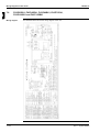
Wiring Diagrams: Outdoor Units
6.1
6.2
6.3
6.4
6.5
6.6
6.7
ii
1–47
1–48
1–50
1–52
1–55
1–56
1–57
1–58
1–59
1–60
1–61
Switch Box Layout
5.1
5.2
5.3
5.4
5.5
6
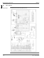
What Is in This Chapter? .........................................................................
RP71........................................................................................................
RP100 and RP125...................................................................................
RYP71, RYP100 and RYP125.................................................................
FHYCP.....................................................................................................
FHYBP.....................................................................................................
FDYP .......................................................................................................
FHYP .......................................................................................................
FUYP .......................................................................................................
FAYP and FHYKP ...................................................................................
FDYMP ....................................................................................................
Functional Diagrams
4.1
4.2
4.3
4.4
4.5
4
5
Specifications
What Is in This Chapter? .........................................................................
RP71-100L7V1 ........................................................................................
RP71-100L7W1 .......................................................................................
RP125L7W1 ............................................................................................
RYP71-100L7V1 ......................................................................................
RYP71-100L7W1 .....................................................................................
RYP125L7W1 ..........................................................................................
1–91
1–92
1–93
1–94
1–95
1–96
1–97
Table of Contents
ESIE03–01
7
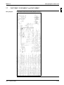
Wiring Diagrams: Indoor Units
7.1
7.2
7.3
7.4
7.7
7.8
7.9
7.10
7.11
What Is in This Chapter? ........................................................................
FHYBP35B7V1, FHYBP45B7V1, FHYBP60B7V1 and FHYBP71B7V1.
FHYBP100B7V1 and FHYBP125B7V1 ..................................................
FHYCP35B7V1, FHYCP45B7V1, FHYCP60B7V1,
FHYCP71B7V1, FHYCP100B7V1 and FHYCP125B7V1 .......................
FDYP125B7V1........................................................................................
FHYP35BV1, FHYP45BV1, FHYP60BV1, FHYP71BV1,
FHYP100BV1 and FHYP125BV1 ...........................................................
FUYP71BV17, FUYP100BV17 and FUYP125BV17 ...............................
FAYP100BV1..........................................................................................
FAYP71LV1 ............................................................................................
FHYKP35BV1, FHYKP45BV1, FHYKP60BV1 and FHYKP71BV1 .........
FDYMP71~125L7V .................................................................................
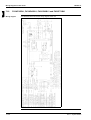
8.1
8.2
8.3
8.4
8.5
8.6
8.7
8.8
8.9
8.10
8.11
What Is in This Chapter? ........................................................................
R(Y)P71~125L7V1 and R(Y)P71~125L7W1 ..........................................
FHYCP35~125B7V1 ...............................................................................
FHYBP35~125B7V1 ...............................................................................
FDYP125~250B7V1................................................................................
FUYP71~125BV1(7) ...............................................................................
FHYKP35~71BV1 ...................................................................................
FHYP35~125BV1....................................................................................
FAYP100BV1..........................................................................................
FAYP71LV1 ............................................................................................
FDYMP71~125L7V1 ...............................................................................
7.5
7.6
8
1–99
1–100
1–101
1–102
1–103
1–104
1–105
1–106
1–107
1–108
1–109
3
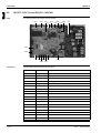
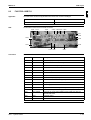
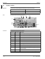
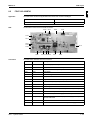
PCB Layout
1–111
1–112
1–113
1–114
1–115
1–116
1–117
1–118
1–119
1–120
1–121
Part 2
Functional Description
1
1
General Functionality
1.1
1.2
1.3
1.4
1.5
1.6
1.7
1.8
1.9
1.10
1.11
1.12
1.13
1.14
1.15
1.16
1.17
Table of Contents
What Is in This Chapter? ........................................................................
Functions of Thermistors ........................................................................
Operating Modes and Control Modes .....................................................
Forced Operating Mode (Emergency Operation)....................................
Outdoor Unit Identification Function........................................................
Thermostat Control .................................................................................
Forced Thermostat OFF .........................................................................
HPS and LPS Function ...........................................................................
Simulated Operation Function ................................................................
Discharge Pipe Temperature Control .....................................................
Gas Shortage Function ...........................................................................
Drain Pump Control ................................................................................
Fan and Flap Operations ........................................................................
Auto-Restart Function .............................................................................
Using Conditions for Remote Controller Thermostat ..............................
Overcurrent Protection Function .............................................................
Expansion Valve Control.........................................................................
2–3
2–4
2–6
2–7
2–10
2–11
2–13
2–14
2–15
2–16
2–17
2–18
2–20
2–21
2–22
2–23
2–24
iii
4
5
ESIE03–01
1
2
2.1
2.2
2.3
2.4
2.5
2.6
2.7
3
3
What Is in This Chapter? .........................................................................
Dry Keep Mode........................................................................................
Freeze-Up Function .................................................................................
Outdoor Fan Starting Control in Cooling or Dry Keep Mode....................
Normal Outdoor Fan Control in Cooling Operation..................................
High Pressure Protection Control in Cooling Operation...........................
Condensation Avoidance Control ............................................................
2–27
2–28
2–29
2–33
2–35
2–37
2–38
Overview of the heating mode functions
3.1
3.2
3.3
3.4
3.5
3.6
3.7
4
5
Overview of the cooling mode functions
What Is in This Chapter? .........................................................................
Defrost Control.........................................................................................
Draft Avoidance Control 1........................................................................
Draft Avoidance Control 2........................................................................
4-way Valve Control.................................................................................
Starting Outdoor Fan Control in Heating Mode .......................................
Normal Outdoor Fan Control in Heating Mode ........................................
2–39
2–40
2–43
2–45
2–46
2–47
2–49
What Is in This Chapter? .........................................................................
Overview of General Problems ................................................................
Emergency Operation and Checking with the Wired Remote Controller .
Procedure of Self-Diagnosis by Remote Controller .................................
Checking with the Wireless Remote Controller Display...........................
Self-Diagnosis by Wired Remote Controller ............................................
Remote Controller Display Malfunction Code and Contens.....................
Troubleshooting with the Indoor Unit LEDs and the Remote Controller ..
Troubleshooting with the Remote Controller: Outdoor Malfunctions .......
Troubleshooting with the Remote Controller: System Malfunctions ........
Overview of the Indoor Safety Devices....................................................
Overview of the Outdoor Safety Devices .................................................
Outdoor Safety Device: Thermal Protector Fan Motor.............................
Outdoor Safety Device: Reverse Phase Protector...................................
Outdoor Safety Device: High-Pressure Switch ........................................
Outdoor Safety Device: Low-Pressure Switch .........................................
3–3
3–4
3–6
3–7
3–8
3–12
3–13
3–15
3–16
3–17
3–18
3–19
3–20
3–21
3–22
3–23
Part 3
Troubleshooting
1
Troubleshooting
1.1
1.2
1.3
1.4
1.5
1.6
1.7
1.8
1.9
1.10
1.11
1.12
1.13
1.14
1.15
1.16
iv
Table of Contents
ESIE03–01
2
Error Codes: Indoor Units
2.1
2.2
2.3
2.4
2.5
2.6
2.7
2.8
3
3–25
3–26
3–27
3–29
3–31
3–32
3–34
3–36
Error Codes: Outdoor Units
3.1
3.2
3.3
3.4
3.5
3.6
3.7
3.8
3.9
3.10
3.11
3.12
3.13
3.14
3.15
4
What Is in This Chapter? ........................................................................
Malfunctioning Indoor PCB ..............................................................(A1)
Malfunctioning Drain Water Level System .......................................(A3)
Indoor Unit Fan Motor Lock .............................................................(A6)
Malfunctioning Drain System .......................................................... (AF)
Malfunctioning Capacity Setting .......................................................(AJ)
Thermistor Abnormality ..........................................................(C4 or C9)
Malfunctioning Remote Controller Air Thermistor ............................ (CJ)
What Is in This Chapter? ........................................................................
Activation of Safety Device .............................................................(EO)
Failure of Outdoor Unit PC Board .................................................... (E1)
Abnormal High Pressure (Detected by the HPS) .............................(E3)
Abnormal Low Pressure (Detected by the LPS) ..............................(E4)
Compressor Overcurrent .................................................................(E6)
Malfunctioning Electronic Expansion Valve .....................................(E9)
Malfunctioning in Discharge Pipe Temperature ...............................(F3)
Malfunctioning HPS ........................................................................ (H3)
Malfunctioning Outdoor Thermistor System .................................... (H9)
Malfunctioning Discharge Pipe Thermistor System ......................... (J3)
Malfunctioning Heat Exchanger Thermistor System ........................ (J6)
Abnormal Heat Exchanging Temperature ........................................(F6)
Malfunction of Current Sensor System ............................................ (J2)
Failure of Capacity Setting ...............................................................(PJ)
3–37
3–38
3–43
3–44
3–46
3–48
3–50
3–52
3–54
3–55
3–56
3–57
3–58
3–59
3–60
Error Codes: System Malfunctions
4.1
4.2
4.3
4.4
4.5
4.6
4.7
Table of Contents
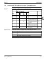
What Is in This Chapter? ........................................................................
Gas Shortage Detection ..................................................................(UO)
Reverse Phase ............................................................................... (U1)
Transmission Error between Indoor and Outdoor Unit ......... (U4 or UF)
Transmission Error between Indoor Unit and Remote Controller ... (U5)
Transmission Error between MAIN Remote Controller
and SUB Remote Controller
(U8)
Malfunctioning Field Setting Switch ................................................ (UA)
3–61
3–62
3–63
3–65
3–67
3–68
3–69
v
1
3
4
5
ESIE03–01
1
5
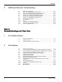
Additional Checks for Troubleshooting
5.1
5.2
5.3
5.4
5.5
5.6
5.7
5.8
5.9
5.10
5.11
5.12
5.13
3
4
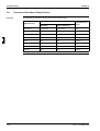
What Is in This Chapter? .........................................................................
Indoor Unit: Checking the Fan Motor Hall IC ...........................................
Indoor Unit: Checking the Power Supply Wave Form..............................
Outdoor Unit: Checking the Refrigerant System......................................
Outdoor unit: Checking the Installation Condition....................................
Outdoor Unit: Checking the Discharge Pressure .....................................
Outdoor Unit: Checking the Expansion Valve..........................................
Checking the Thermistors........................................................................
R1T and R2T ...........................................................................................
R3T ..........................................................................................................
Evaluation of abnormal high pressure .....................................................
Evaluation of abnormal low pressure.......................................................
Check for Clogged Points ........................................................................
3–71
3–72
3–73
3–74
3–75
3–76
3–77
3–78
3–79
3–80
3–81
3–82
3–83
Part 4
Commissioning and Test Run
1
Pre-Test Run Checks
5
2
1.1
1.2
1.3
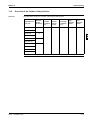
What Is in This Chapter? .........................................................................
Test Run Checks .....................................................................................
Setting the Wireless Remote Controller...................................................
4–3
4–4
4–5
2.1
2.2
2.3
2.4
2.5
2.6
2.7
2.8
2.9
2.10
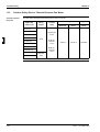
What Is in This Chapter? .........................................................................
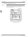
How to Change the Field Settings with the Wired Remote Controller .....
How to Change the Field Settings with the Wireless Remote Controller .
Overview of the Field Settings of the Indoor Units...................................
Overview of the Factory Settings of the Indoor Units...............................
Setting the Ceiling Height ........................................................................
Setting the Filter Counter.........................................................................
MAIN/SUB Setting when Using Two Remote Controllers........................
Setting the Centralized Group No. ...........................................................
Field settings when using a spare part PCB of Sky-Air L-series
outdoor unit..............................................................................................
The Field Setting Levels ..........................................................................
Overview of the Field Settings: R(Y)P71-125L ........................................
Jumpers ...................................................................................................
DIP switch DS1........................................................................................
DIP switch DS2........................................................................................
4–9
4–10
4–12
4–13
4–14
4–15
4–16
4–17
4–18
Field settings
2.11
2.12
2.13
2.14
2.15
vi
4–20
4–23
4–26
4–28
4–29
4–30
Table of Contents
ESIE03–01
3
Test Run and Operation Data
3.1
3.2
3.3
General Operation Data ..........................................................................
RP71L7V1, RP71L7W1, RP100L7V1, RP100L7W1 and RP125L7W1 ..
RYP71L7V1, RYP71L7W1, RYP100L7V1, RYP100L7W1
and RYP125L7W1 ..................................................................................
4–34
4–36
1
4–37
Part 5
Disassembly and Maintenance
1
1.1
1.2
1.3
1.4
1.5
1.6
1.7
2
3
Disassembly and Maintenance: Outdoor Units
What Is in This Chapter? ........................................................................
RP71L7V1, RP71L7W1 ..........................................................................
RYP71L7V1 and RYP71L7W1 ...............................................................
RP100L7V1, RP100L7W1 ......................................................................
RP125L7W1............................................................................................
RYP100L7V1, RYP100L7W1 .................................................................
RYP125L7W1 .........................................................................................
5–3
5–4
5–6
5–8
5–10
5–12
5–14
5
Disassembly and Maintenance: Indoor Units
2.1
2.2
2.3
2.4
2.5
2.6
2.7
2.8
2.9
2.10
2.11
2.12
Table of Contents
What Is in This Chapter? ........................................................................
FHYCP35B7V1, FHYCP45B7V1, FHYCP60B7V1 and FHYCP71B7V1
FHYBP35B7V1 and FHYBP45B7V1 ......................................................
FHYBP60B7V1 and FHYBP71B7V1 ......................................................
FHYBP100B7V1 and FHYBP125B7V1 ..................................................
FDYP125B7V1........................................................................................
FHYP35BV1 and FHYP45BV1 ...............................................................
FHYP60BV1 and FHYP71BV1 ...............................................................
FHYKP35BV1, FHYKP45BV1, FHYKP60BV1 and FHYKP71BV1 .........
FHYP100BV1 and FHYP125BV1 ...........................................................
FUYP71~125BV17..................................................................................
FAYP71LV1 ............................................................................................
4
5–17
5–18
5–20
5–22
5–24
5–26
5–28
5–30
5–32
5–34
5–47
5–63
vii
ESIE03–01
1
3
4
5
viii
Table of Contents
ESIE03–01
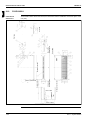
Introduction
Part 0
1
Introduction
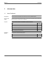
1.1
About This Manual
Target group
This service manual is intended for and should only be used by qualified engineers.
Purpose of this
manual
This service manual contains all the information you need to do the necessary repair and maintenance
tasks for the Sky Air L-series room air conditioners.
Five parts
This service manual consists of an introduction, five parts and an index:
Introduction
overview
Part
See page
Part 1–System Outline
1–1
Part 2–Functional Description
2–1
Part 3–Troubleshooting
3–1
Part 4–Commissioning and Test Run
4–1
Part 5–Disassembly and Maintenance
5–1
4
5
The introduction contains the following topics:
Topic
See page
1.2–Combination Overview: Outdoor Units of the Sky Air L-Series
x
3
ix
Introduction
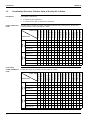
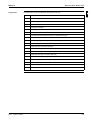
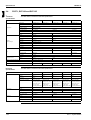
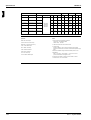
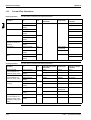
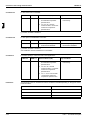
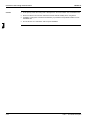
Combination Overview: Outdoor Units of the Sky Air L-Series
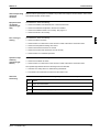
P
“P” stands for pair combination.
P
“T” stands for twin, triple or double twin combination.
FHYKP60BV17
FHYKP71BV17
FHYP35BV1
—
P
—
—
T
—
—
P
T
RP71L7W1
T
—
—
P
—
—
T
—
—
P
T
RP100L7V1
T
T
T
T
P
—
T
T
T
T
T
Large
c/o
RP100L7W1
T
T
T
T
P
—
T
T
T
T
RP125L7W1
T
T
T
T
—
P
T
T
T
RYP71L7V1
T
—
—
P
—
—
T
—
RYP71L7W1
T
—
—
P
—
—
T
Large
h/p
RYP100L7V1
T
T
T
T
P
—
RYP100L7W1
T
T
T
T
P
RYP125L7W1
T
T
T
T
—
—
—
—
P
—
—
T
T
T
P
—
T
T
T
T
P
—
T
T
T
T
T
—
P
—
P
T
—
—
P
—
—
—
—
P
T
—
P
—
—
T
T
T
T
T
T
T
T
P
—
—
T
T
T
T
T
T
T
T
P
—
P
T
T
T
T
T
T
T
T
—
P
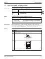
FAYP71LV1
FAYP71LV1
FAYP100BV1
FHYBP35B7V1
FHYBP45B7V1
FHYBP60B7V1
FHYBP71B7V1
FHYBP100B7V1
FHYBP125B7V1
FDYMP71L7V1
FDYMP100L7V1
FDYMP125L7V1
FDYP125B7V1
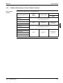
The table below contains the possible combinations between indoor units (FUYP, FAYP, FHYBP,
FDYMP and FDYP) and outdoor units of the Sky Air L-series.
RP71L7V1
P
—
—
P
P
—
T
—
—
P
—
—
P
—
—
—
RP71L7W1
P
—
—
P
P
—
T
—
—
P
—
—
P
—
—
—
RP100L7V1
T
P
—
T
T
P
T
T
T
T
P
—
T
P
—
—
RP100L7W1
T
P
—
T
T
P
T
T
T
T
P
—
T
P
—
—
RP125L7W1
T
—
P
T
T
—
T
T
T
T
—
P
T
—
P
P
RYP71L7V1
P
—
—
P
P
—
T
—
—
P
—
—
P
—
—
—
RYP71L7W1
P
—
—
P
P
—
T
—
—
P
—
—
P
—
—
—
RYP100L7V1
T
P
—
T
T
P
T
T
T
T
P
—
T
P
—
—
RYP100L7W1
T
P
—
T
T
P
T
T
T
T
P
—
T
P
—
—
RYP125L7W1
T
—
P
T
T
—
T
T
T
T
—
P
T
—
P
P
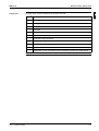
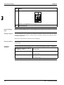
Indoor unit
Large
h/p
Large
c/o
Outdoor unit
x
P
FUYP125BV17
FUYP, FAYP,
FHYBP, FDYMP and
FDYP
—
FUYP100BV17
5
—
FUYP71BV17
4
FHYP125BV1
FHYKP45BV17
—
FHYP100BV1
FHYKP35BV17
T
Outdoor unit
FHYP71BV1
FHYCP125B7V1
3
FHYP60BV1
FHYCP100B7V1
RP71L7V1
Indoor unit
FHYP45BV1
FHYCP71B7V1
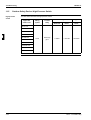
The table below contains the possible combinations between indoor units (FHYCP, FHYKP and
FHYP) and outdoor units of the Sky Air L-series.
FHYCP60B7V1
FHYCP, FHYKP and
FHYP
In the tables in this section:
FHYCP45B7V1
Introduction
FHYCP35B7V1
1
1.2
ESIE03–01
ESIE03–01
1
4
Part 1
System Outline
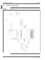
What is in this part?
Part 1 – System Outline
3
This part contains the following chapters:
Chapter
See page
1–General Outline: Outdoor Units
1–3
2–General Outline: Indoor Units
1–13
3–Specifications
1–47
4–Functional Diagrams
1–63
5–Switch Box Layout
1–77
6–Wiring Diagrams: Outdoor Units
1–91
7–Wiring Diagrams: Indoor Units
1–99
8–PCB Layout
1–111
4
5
1–1
ESIE03–01
11
3
5
1–2
Part 1 – System Outline
ESIE03–01
General Outline: Outdoor Units
Part 1
1
General Outline: Outdoor Units
1.1
What Is in This Chapter?
Introduction
General outline
Part 1 – System Outline
This chapter contains the following information on the outdoor units:
P
Outlook and dimensions
P
Installation and service space
P
Components.
1
3
This chapter contains the following general outlines:
General outline
See page
1.2–RP71L7V1, RP71L7W1, RYP71L7V1, RYP71L7W1
1–4
1.3–RP100L7V1, RP100L7W1, RYP100L7V1, RYP100L7W1
1–6
1.4–RP125L7W1 and RYP125L7W1
1–8
1.5–RP71L7V1, RP71L7W1, RP100L7V1, RP100L7W1, RP125L7W1,
RYP71L7V1, RYP71L7W1, RYP100L7V1, RYP100L7W1, RYP125L7W1:
Installation and Service Space
1–10
4
5
1–3
General Outline: Outdoor Units
11
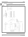
1.2
ESIE03–01
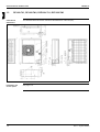
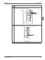
RP71L7V1, RP71L7W1, RYP71L7V1, RYP71L7W1
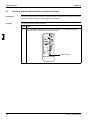
Outlook and
dimensions
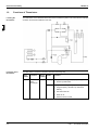
The illustration below shows the outlook and the dimensions of the unit (mm).
Installation and
service space
See page 1–10.
3
4
5
1–4
Part 1 – System Outline
ESIE03–01
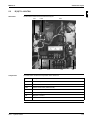
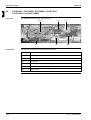
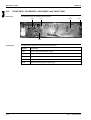
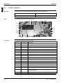
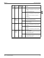
Components
General Outline: Outdoor Units
1
The table below contains the different components of the unit.
No.
Component
1
Gas pipe connection
2
Liquid pipe connection
3
Service port (inside the unit)
4
Grounding terminal M5 (inside the switch box)
5
Refrigerant piping intake
6
Power supply wiring intake
7
Control wiring intake
8
Drain outlet
3
4
5
Part 1 – System Outline
1–5
General Outline: Outdoor Units
11
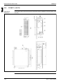
1.3
ESIE03–01
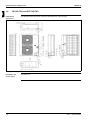
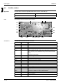
RP100L7V1, RP100L7W1, RYP100L7V1, RYP100L7W1
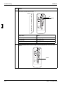
Outlook and
dimensions
The illustration below shows the outlook and the dimensions of the unit (mm).
Installation and
service space
See page 1–10.
3
4
5
1–6
Part 1 – System Outline
ESIE03–01
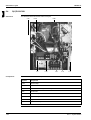
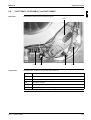
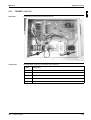
Components
General Outline: Outdoor Units
1
The table below contains the different components of the unit.
No.
Component
1
Gas pipe connection
2
Liquid pipe connection
3
Service port (inside the unit)
4
Grounding terminal M5 (inside the switch box)
5
Refrigerant piping intake
6
Power supply wiring intake
7
Control wiring intake
8
Drain outlet
3
4
5
Part 1 – System Outline
1–7
General Outline: Outdoor Units
11
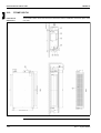
1.4
ESIE03–01
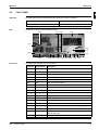
RP125L7W1 and RYP125L7W1
Outlook and
dimensions
The illustration below shows the outlook and the dimensions of the unit (mm).
Installation and
service space
See page 1–10.
3
4
5
.
1–8
Part 1 – System Outline
ESIE03–01
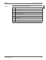
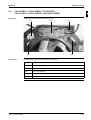
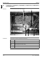
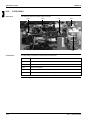
Components
General Outline: Outdoor Units
1
The table below contains the different components of the unit.
No.
Component
1
Gas pipe connection
2
Liquid pipe connection
3
Service port (inside the unit)
4
Grounding terminal M5 (inside the switch box)
5
Refrigerant piping intake
6
Power supply wiring intake
7
Control wiring intake
8
Drain outlet
3
4
5
Part 1 – System Outline
1–9
General Outline: Outdoor Units
11
1.5
ESIE03–01
RP71L7V1, RP71L7W1, RP100L7V1, RP100L7W1, RP125L7W1,
RYP71L7V1, RYP71L7W1, RYP100L7V1, RYP100L7W1, RYP125L7W1:
Installation and Service Space
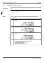
Non stacked
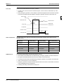
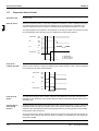
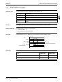
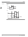
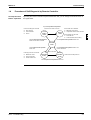
The illustrations and table below show the required installation and service space (mm). The values in
brackets are for the 100 and 125 class.
3
4
5
Suction side obstacle
1
In these cases, close the bottom
of the installation frame to
prevent discharged air from being
bypassed
2
In these cases, only 2 units can
be installed
Discharge side obstacle
Left side obstacle
Right side obstacle
This situation is not allowed
Top side obstacle
Obstacle is present
1–10
Part 1 – System Outline
ESIE03–01
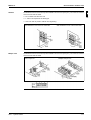
Stacked
General Outline: Outdoor Units
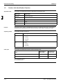
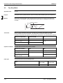
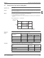
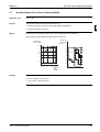
The illustration below shows the required installation and service space (mm). The values in brackets
are for the 100 and 125 class.
P
Do not stack more than one unit.
P
± 100 mm is required for the drain pipe.
P
Seal A in order to prevent outlet air from bypassing.
With obstacles in front of the air outlet side
1
With obstacles in front of the air inlet side
3
4
Multiple rows
The illustration below shows the required installation and service space (mm). The values in brackets
are for the 100 and 125 class.
One unit per row
5
Multiple units per row
installation impossible
Part 1 – System Outline
1–11
General Outline: Outdoor Units
ESIE03–01
11
3
4
5
1–12
Part 1 – System Outline
ESIE03–01
General Outline: Indoor Units
Part 1
2
General Outline: Indoor Units
2.1
What Is in This Chapter?
Introduction
General outline
Part 1 – System Outline
This chapter contains the following information on the indoor units:
P
Outlook and dimensions
P
Installation and service space
P
Components.
1
3
This chapter contains the following general outlines:
General outline
See page
2.2–FHYCP35B7V1, FHYCP45B7V1, FHYCP60B7V1 and FHYCP71B7V1
1–14
2.3–FHYBP35B7V1 and FHYBP45B7V1
1–16
2.4–FHYBP60B7V1 and FHYBP71B7V1
1–17
2.5–FHYBP100B7V1 and FHYBP125B7V1
1–18
2.6–FHYCP100B7V1 and FHYCP125B7V1
1–19
2.7–FDYP125B7V1
1–21
2.8–FHYP35BV1 and FHYP45BV1
1–22
2.8–FHYP35BV1 and FHYP45BV1
1–22
2.9–FHYP60BV1 and FHYP71BV1
1–24
2.10–FHYP100BV1
1–26
2.11–FHYP125BV1
1–28
2.12–FUYP71BV17
1–30
2.13–FUYP100BV17 and FUYP125BV17
1–32
2.14–FAYP71LV1
1–34
2.15–FAYP100BV1
1–36
2.16–FHYKP35BV17 and FHYKP45BV17
1–38
2.17–FHYKP60BV17 and FHYKP71BV17
1–40
2.18–FDYMP71~100L7V1
1–42
2.19–FDYMP125L7V1
1–44
4
5
1–13
General Outline: Indoor Units
11
2.2
ESIE03–01
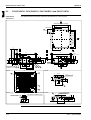
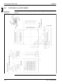
FHYCP35B7V1, FHYCP45B7V1, FHYCP60B7V1 and FHYCP71B7V1
Outlook and
dimensions
The illustration below shows the outlook and the dimensions of the unit (mm).
B
860~890 (Ceiling opening)
680 (Suspension position)
420
300 or less
780 Suspension position
860~890 Ceiling opening
10
3
420
3
C
55
840
55
55
840
55
30
295
5
4
260
4 x M8~M10
1
12
2
315
View A
160
95
240
150
125
150
95
40
350
350
8
85
110
80
2x100=200
110
80 2x100=200
80
20
Suspension bolt
12 x M4
295
200
750
10
230
160
A
View B
950
9
11
80
2X100=200
85
12 x M4
95
40
110
950
160
Prepared hole
350
6
12
7
80
80
Prepared hole
2x100=200
80
160
D75
12 x M4
12
95
Prepared hole
For fresh air intake kit connec- View D
tion (direct installation type)
110
60
4 x M4
165
View C
80
5
Adjustable (0~550)
4
D
350
1–14
Part 1 – System Outline
ESIE03–01
The illustration below shows the required installation and service space. When a discharge grille is
closed (e.g. 3-way blow application), the required space is 200 mm or more (mm).
15
15
00
or
mo
0
r
0o
mo
15
0
r
0o
mo
A
Part 1 – System Outline
00
or
mo
re
re
15
Components
1
re
re
3
4
1000 or more
Installation and
service space
General Outline: Indoor Units
5
The table below contains the different components of the unit.
No.
Component
1
Liquid pipe connection
2
Gas pipe connection
3
Drain pipe connection
4
Power supply connection
5
Transmission wiring connection
6
Air discharge grille
7
Air suction grille
8
Water supply intake
9
Corner decoration cover
10
Drain hose
11
In case a wireless remote controller is used, this position is a signal receiver.
12
Branch duct connection
1–15
General Outline: Indoor Units
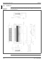
FHYBP35B7V1 and FHYBP45B7V1
The illustration below shows the outlook, the dimensions and the installation and service space of the
unit (mm).
60
25
595
1
8
3
10
130
67
135
2x65 =
150
215
245
300
3
315
Suspension bolt
195
65
C
800
50
9
3x150 =
450
A
57
45
B
46
2
485
350 or more
700
460
200
Outlook,
dimensions and
installation and
service space
150
11
2.3
ESIE03–01
6
4
5
300 or more
4
View A
View B
6x65 =
View C
390
160 P.C.D.
145
600
39
178
98
98
152
D125
14 x M4
Knock out hole
600
7
750
250
150
650
Suspension
position
Components
1–16
230
60 110
630
4x150 =
100
630
5
Fresh air intake
6 x M5
14 x M5
The table below contains the different components of the unit.
No.
Component
1
Liquid pipe connection
2
Gas pipe connection
3
Drain pipe connection (O.D. 32 mm, I.D. 25 mm)
4
Remote controller wiring connection
5
Power supply connection
6
Drain hole (O.D. 32 mm, I.D. 25 mm)
7
Air filter
8
Air suction side
9
Air discharge side
10
Name plate
Part 1 – System Outline
ESIE03–01
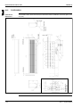
FHYBP60B7V1 and FHYBP71B7V1
The illustration below shows the outlook, the dimensions and the installation and service space of the
unit (mm).
60
25
50
Suspension bolt
315
3
10
8
195
130
1
2x65 =
150
215
245
135
67
65
300
800
595
9
5x150 =
750
A
57
45
46
2
785
6
4
350 or more
1000
760
C
1
200
Outlook,
dimensions and
installation and
service space
150
2.4
General Outline: Indoor Units
B
3
5
500 or more
View A
View B
View C
11x65 = 715
141.5 107 115.5 98
141.5 107 115.5
20 x M4
900
Components
Part 1 – System Outline
4
150
5
6 x M5
950
Suspension position
250
230
60 110
630
7
1050
600
D125
Knock out hole
930
6x150 =
Fresh air intake
100
145
160 P.C.D.
39
18 x M5
The table below contains the different components of the unit.
No.
Component
1
Liquid pipe connection
2
Gas pipe connection
3
Drain pipe connection (O.D. 32 mm, I.D. 25 mm)
4
Remote controller wiring connection
5
Power supply connection
6
Drain hole (O.D. 32 mm, I.D. 25 mm)
7
Air filter
8
Air suction side
9
Air discharge side
10
Name plate
1–17
General Outline: Indoor Units
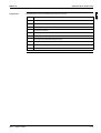
FHYBP100B7V1 and FHYBP125B7V1
The illustration below shows the outlook, the dimensions and the installation and service space of the
unit (mm).
60
25
595
Suspension bolt
3
8
3
195
130
10
9
7x150 =
1050
57
45
A
46
2
1185
6
4
5
B
500 or more
View A
View B
16x65 =
View C
1040
160 P.C.D.
145
98
98
98
178
98
98
152
D125
24 x M4
Knock out hole
1254
1350
150
230
250
7
6 x M5
1350
1450
5
152
100
178
9x150 =
60 110
630
Fresh air intake
600
39
Susp. position
4
315
1
2x65 =
150
215
245
300
135
67
65
C
800
50
350 or more
1400
1160
200
Outlook,
dimensions and
installation and
service space
150
11
2.5
ESIE03–01
24 x M5
Suspension position
Components
1–18
The table below contains the different components of the unit.
No.
Component
1
Liquid pipe connection
2
Gas pipe connection
3
Drain pipe connection (O.D. 32 mm, I.D. 25 mm)
4
Remote controller wiring connection
5
Power supply connection
6
Drain hole (O.D. 32 mm, I.D. 25 mm)
7
Air filter
8
Air suction side
9
Air discharge side
10
Name plate
Part 1 – System Outline
ESIE03–01
2.6
General Outline: Indoor Units
FHYCP100B7V1 and FHYCP125B7V1
Outlook and
dimensions
1
The illustration below shows the outlook and the dimensions of the unit (mm).
B
860~890 Ceiling opening
680 Suspension position
420
300 or less
780 Suspension position
860~890 Ceiling opening
10
420
12 x M4
3
D
4
C
3
12 x M4
55
298
150
150
125
194.5
165
155
200
10
288
20
30
40
5
85
190
80 2x100=200
40
80
750
80 2x100=200
55
840
155
55
12
165
840
295
50
55
40
350
Suspension bolt
4 x M8~M10
260
8
5
295
315
4
1
12
350
2
A
950
View A
View B
9
85 2x100=200
80
165
155
190
11
12 x M4
950
Prepared hole
40
350
6
12
7
80
80
D75
View D
12 x M4
12
80 2x100=200
Prepared hole
80
190
Prepared hole
For fresh air intake kit connection (direct inistallation type)
155
165
60
4 x M4
165
View C
350
Part 1 – System Outline
1–19
General Outline: Indoor Units
11
Installation and
service space
ESIE03–01
The illustration below shows the installation and service space (mm). When a discharge grille is closed
(e.g. 3-way blow application), the required space is 200 mm or more.
15
0
r
0o
mo
re
15
15
00
or
mo
00
or
mo
re
re
3
15
o
00
rm
ore
5
A
Components
1–20
1000 or more
4
The table below contains the different components of the unit.
No.
Component
1
Liquid pipe connection
2
Gas pipe connection
3
Drain pipe connection (O.D. 32 mm, I.D. 25 mm)
4
Power supply connection
5
Transmission wiring connection
6
Air discharge grille
7
Air suction grille
8
Water supply intake
9
Corner decoration cover
10
Drain hose (O.D. 32 mm)
11
In case a wireless remote controller is used, this position is a signal receiver.
12
Branch duct connection
Part 1 – System Outline
ESIE03–01
2.7
General Outline: Indoor Units
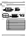
FDYP125B7V1
Outlook,
dimensions and
installation and
service space
1
The illustration below shows the outlook, the dimensions and the installation and service space of the
unit (mm).
82
96
131
662
331
220
174
30
4
20
350
55
A
3
≥ 350
5
2
3
1
39
1150
189
≥ 300
≥ 300
4
1400
202
26.5
View A
≥ 300
694
5
353
Service space
Components
Part 1 – System Outline
The table below contains the different components of the unit.
No.
Component
1
Power supply intake
2
Drain connection (O.D. 25 mm)
3
Gas pipe connection
4
Liquid pipe connection
5
Filter
1–21
General Outline: Indoor Units
11
2.8
ESIE03–01
FHYP35BV1 and FHYP45BV1
The illustration below shows the outlook, the dimensions and the installation and service space of the
unit (mm).
Front view
Outlook and
dimensions
Front view
3
Drain pipe connection
30 or more
Service space
Suspension bolt
Suspension position
5
Name plate
30 or more
Service space
4
Suspension position
Floor
Obstacle
300 or more
2500 or more
1–22
Part 1 – System Outline
ESIE03–01
Components
Part 1 – System Outline
General Outline: Indoor Units
1
The table below contains the different components of the unit.
No.
Component
1
Air discharge grille
2
Air suction grille
3
Air filter
4
Gas pipe connection
5
Liquid pipe connection
6
Drain pipe connection
7
Grounding terminal (inside the electric components box) M4
8
Suspension bracket
9
Backward piping and wiring connection opening lid
10
Upward piping and wiring connection opening lid
11
Right side pipe connection (slit hole)
12
Left back drain pipe connection (slit hole)
13
Left side drain pipe connection (slit hole)
14
Right side drain pipe connection (slit hole)
15
Wall hole for taking out in piping back (∅ 100 mm)
16
Upward drain pipe connection (∅ 60 mm)
17
Upward gas pipe connection (∅ 36 mm)
18
Upward liquid pipe connection (∅ 26 mm)
—
Name plate: In case of a wireless remote controller, this position is a signal receiver.
3
4
5
1–23
General Outline: Indoor Units
11
2.9
ESIE03–01
FHYP60BV1 and FHYP71BV1
The illustration below shows the outlook, the dimensions and the installation and service space of the
unit (mm).
Front view
Outlook and
dimensions
30 or more
Service space
4
Name plate
Front view
3
Drain pipe connection
30 or more
Service space
Suspension bolt
Suspension position
5
Suspension position
Floor
Obstacle
300 or more
2500 or more
1–24
Part 1 – System Outline
ESIE03–01
Components
Part 1 – System Outline
General Outline: Indoor Units
1
The table below contains the different components of the unit.
No.
Component
1
Air discharge grille
2
Air suction grille
3
Air filter
4
Gas pipe connection
5
Liquid pipe connection
6
Drain pipe connection
7
Grounding terminal (inside the electric components box) M4
8
Suspension bracket
9
Backward piping and wiring connection opening lid
10
Upward piping and wiring connection opening lid
11
Right side pipe connection (slit hole)
12
Left back drain pipe connection (slit hole)
13
Left side drain pipe connection (slit hole)
14
Right side drain pipe connection (slit hole)
15
Wall hole for taking out in piping back (∅ 100 mm)
16
Upward drain pipe connection (∅ 60 mm)
17
Upward gas pipe connection (∅ 36 mm)
18
Upward liquid pipe connection (∅ 26 mm)
—
Name plate: In case of a wireless remote controller, this position is a signal receiver.
3
4
5
1–25
General Outline: Indoor Units
11
2.10
ESIE03–01
FHYP100BV1
The illustration below shows the outlook, the dimensions and the installation and service space of the
unit (mm).
Front view
Outlook and
dimensions
30 or more
Service space
4
Name plate
Front view
3
Drain pipe connection
30 or more
Service space
Suspension bolt
Suspension position
5
Suspension position
Floor
Obstacle
300 or more
2500 or more
1–26
Part 1 – System Outline
ESIE03–01
Components
Part 1 – System Outline
General Outline: Indoor Units
1
The table below contains the different components of the unit.
No.
Component
1
Air discharge grille
2
Air suction grille
3
Air filter
4
Gas pipe connection
5
Liquid pipe connection
6
Drain pipe connection
7
Grounding terminal (inside the electric components box) M4
8
Suspension bracket
9
Backward piping and wiring connection opening lid
10
Upward piping and wiring connection opening lid
11
Right side pipe connection (slit hole)
12
Left back drain pipe connection (slit hole)
13
Left side drain pipe connection (slit hole)
14
Right side drain pipe connection (slit hole)
15
Wall hole for taking out in piping back (∅ 100 mm)
16
Upward drain pipe connection (∅ 60 mm)
17
Upward gas pipe connection (∅ 36 mm)
18
Upward liquid pipe connection (∅ 26 mm)
—
Name plate: In case of a wireless remote controller, this position is a signal receiver.
3
4
5
1–27
General Outline: Indoor Units
11
2.11
ESIE03–01
FHYP125BV1
The illustration below shows the outlook, the dimensions and the installation and service space of the
unit (mm).
Front view
Outlook and
dimensions
30 or more
Service space
Name plate
Front view
3
4
Suspension position
300 or more
Obstacle
Floor
Drain pipe connection
30 or more
Service space
Suspension bolt
Suspension position
5
2500 or more
1–28
Part 1 – System Outline
ESIE03–01
Components
Part 1 – System Outline
General Outline: Indoor Units
1
The table below contains the different components of the unit.
No.
Component
1
Air discharge grille
2
Air suction grille
3
Air filter
4
Gas pipe connection
5
Liquid pipe connection
6
Drain pipe connection
7
Grounding terminal (inside the electric components box) M4
8
Suspension bracket
9
Backward piping and wiring connection opening lid
10
Upward piping and wiring connection opening lid
11
Right side pipe connection (slit hole)
12
Left back drain pipe connection (slit hole)
13
Left side drain pipe connection (slit hole)
14
Right side drain pipe connection (slit hole)
15
Wall hole for taking out in piping back (∅ 100 mm)
16
Upward drain pipe connection (∅ 60 mm)
17
Upward gas pipe connection (∅ 36 mm)
18
Upward liquid pipe connection (∅ 26 mm)
—
Name plate: In case of a wireless remote controller, this position is a signal receiver.
3
4
5
1–29
General Outline: Indoor Units
11
2.12
ESIE03–01
FUYP71BV17
The illustration below shows the outlook, the dimensions and the installation and service space of the
unit (mm).
re
mo
or
00
15
790 Suspension position
Suspension bolt
0
15
790 Suspension position
4
Suspension bracket
15
re
mo
r
0o
3
1000 or more
o
00
rm
15
or e
00
or
mo
re
Outlook and
dimensions
1–30
Name plate
Upper piping
Drain connection location
Rear piping
5
Part 1 – System Outline
ESIE03–01
Components
General Outline: Indoor Units
1
The table below contains the different components of the unit.
No.
Component
1
Liquid pipe connection
2
Gas pipe connection
3
Drain pipe connection
4
Air outlet
5
Air suction grille
6
Corner decoration panel
7
Right pipe / wiring connection
8
Rear pipe / wiring connection
9
Pipe through cover
10
Accessory drain elbow
—
Name plate: In case of a wireless remote controller, this position is a signal receiver.
3
4
5
Part 1 – System Outline
1–31
General Outline: Indoor Units
11
2.13
ESIE03–01
FUYP100BV17 and FUYP125BV17
The illustration below shows the outlook, the dimensions and the installation and service space of the
unit (mm).
15
790 Suspension position
Suspension bolt
00
or
mo
re
15
0
790 Suspension position
4
Suspension bracket
15
0
r
0o
re
mo
r
0o
3
1000 or more
15
mo
re
00
or
mo
re
Outlook and
dimensions
1–32
Name plate
Upper piping
Drain connection location
Rear piping
5
Part 1 – System Outline
ESIE03–01
Components
General Outline: Indoor Units
1
The table below contains the different components of the unit.
No.
Component
1
Liquid pipe connection
2
Gas pipe connection
3
Drain pipe connection
4
Air outlet
5
Air suction grille
6
Corner decoration panel
7
Right pipe / wiring connection
8
Rear pipe / wiring connection
9
Pipe through cover
10
Accessory drain elbow
—
Name plate: In case of a wireless remote controller, this position is a signal receiver.
3
4
5
Part 1 – System Outline
1–33
General Outline: Indoor Units
11
2.14
ESIE03–01
FAYP71LV1
Outlook and
dimensions
The illustration below shows the outlook, the dimensions and the installation and service space of the
unit (mm).Components
3
4
5
1–34
Part 1 – System Outline
ESIE03–01
Components
General Outline: Indoor Units
The table below contains the different components of the unitThe table below contains the different
components of the unit.
No.
Component
1
Front panel
2
Front grill
3
Air outlet
4
Gas pipe
5
Liquid pipe
6
Drain hose
7
Grounding terminal
8
Right side pipe connection hole
9
Left side pipe connection hole
1
3
4
5
Part 1 – System Outline
1–35
General Outline: Indoor Units
11
2.15
ESIE03–01
FAYP100BV1
Outlook and
dimensions
The illustration below shows the outlook, the dimensions and the installation and service space of the
unit (mm).
Direction for air filter
draw out
250 or more
4
± 450
± 580
± 600
50 or more
50 or more
Piping
direction
Name plate
3
1–36
Mounting hole for
installation plate
Detail A
50 or more
5
Part 1 – System Outline
ESIE03–01
Components
General Outline: Indoor Units
1
The table below contains the different components of the unit.
No.
Component
1
Front grille
2
Air filter
3
Discharge outlet
4
Gas pipe connection
5
Liquid pipe connection
6
Drain pipe connection (O.D. 26 mm)
7
Grounding terminal M4 (inside the cover)
8
Slit hole for right piping connection
9
Slit hole for left piping connection
—
Name plate: In case of a wireless remote controller, this position is a signal receiver.
3
4
5
Part 1 – System Outline
1–37
General Outline: Indoor Units
FHYKP35BV17 and FHYKP45BV17
r
0o
20 re
mo
or
00
15 r e
mo
Required space
4
200 or
more
200 or
m
3
Hole
The illustration below shows the outlook, the dimensions and the installation and service space of the
unit (mm).
ore
Outlook and
dimensions
Fresh air intake position
11
2.16
ESIE03–01
Suspension bolt
Hole
Ceiling opening
Suspension position
1000 or more
Front discharge dust
connection postion
5
350 Suspension position
760 Ceiling opening
1–38
Part 1 – System Outline
ESIE03–01
Components
General Outline: Indoor Units
1
The table below contains the different components of the unit.
No.
Component
1
Liquid pipe connection
2
Gas pipe connection
3
Drain pipe connection
4
Wire intake
5
Wire intake for remote control
6
Grounding terminal M4 (inside the switch box)
7
Air discharge grille
8
Air suction grille
9
Air filter
10
Suspension bracket
3
4
5
Part 1 – System Outline
1–39
General Outline: Indoor Units
FHYKP60BV17 and FHYKP71BV17
Suspension bolt
Hole
Suspension position
Ceiling opening
Front discharge dust
connection postion
5
or
00
15 re
r
mo
0o
20 re
mo
Required space
4
200 or
more
200 or
more
3
Hole
The illustration below shows the outlook, the dimensions and the installation and service space of the
unit (mm).
Fresh air intake position
Outlook and
dimensions
1000 or more
11
2.17
ESIE03–01
350 Suspension position
760 Ceiling opening
1–40
Part 1 – System Outline
ESIE03–01
Components
General Outline: Indoor Units
1
The table below contains the different components of the unit.
No.
Component
1
Liquid pipe connection
2
Gas pipe connection
3
Drain pipe connection
4
Wire intake
5
Wire intake for remote control
6
Grounding terminal M4 (inside the switch box)
7
Air discharge grille
8
Air suction grille
9
Air filter
10
Suspension bracket
3
4
5
Part 1 – System Outline
1–41
General Outline: Indoor Units
11
2.18
ESIE03–01
FDYMP71~100L7V1
Outlook and
dimensions
The illustration below shows the outlook, the dimensions and the installation and service space of the
unit (mm).
3
4
5
1–42
Part 1 – System Outline
ESIE03–01
Components
General Outline: Indoor Units
1
The table below contains the different components of the unit.
No.
Component
1
Liquid pipe connection
2
Gas pipe connection
3
Remote controller wiring connection
4
Power supply connection
5
Drain pipe connection (O.D. 32 mm)
6
Air filter
7
Air suction side
8
Air discharge side
9
Nameplate
3
4
5
Part 1 – System Outline
1–43
General Outline: Indoor Units
11
2.19
ESIE03–01
FDYMP125L7V1
Outlook and
dimensions
The illustration below shows the outlook, the dimensions and the installation and service space of the
unit (mm).
3
4
5
1–44
Part 1 – System Outline
ESIE03–01
Components
General Outline: Indoor Units
1
The table below contains the different components of the unit.
No.
Component
1
Liquid pipe connection
2
Gas pipe connection
3
Remote controller wiring connection
4
Power supply connection
5
Drain pipe connection (O.D. 32 mm)
6
Air filter
7
Air suction side
8
Air discharge side
9
Nameplate
3
4
5
Part 1 – System Outline
1–45
General Outline: Indoor Units
ESIE03–01
11
3
4
5
1–46
Part 1 – System Outline
ESIE03–01
Specifications
Part 1
3
Specifications
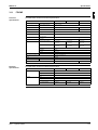
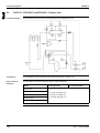
3.1
What Is in This Chapter?
Introduction
This chapter contains the following information:
P
Technical specifications
P
Electrical specifications.
Options
For possible options, refer to OHE03-2 or the installation manual.
Outdoor units
This chapter contains the following specifications:
Indoor units
Part 1 – System Outline
1
3
4
Specifications
See page
3.2–RP71
1–48
3.3–RP100 and RP125
1–50
3.4–RYP71, RYP100 and RYP125
1–52
5
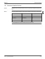
This chapter contains the following specifications:
Specifications
See page
3.5–FHYCP
1–55
3.6–FHYBP
1–56
3.7–FDYP
1–57
3.8–FHYP
1–58
3.9–FUYP
1–59
3.10–FAYP and FHYKP
1–60
3.11–FDYMP
1–61
1–47
Specifications
11
3.2
ESIE03–01
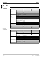
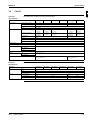
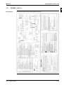
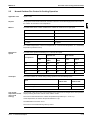
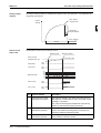
RP71
Technical
specifications
The table below contains the technical specifications.
Specification
Model x No.
Compressor
3
5
RP71L7W1
JT90FA-YE x 1
Type
Hermetically sealed scroll type
Refrigerant oil type
DAPHNE FVC68D
Speed
rpm
Oil charge
1200 cc
Length
859 mm
Rows x stages x fin pitch
2 x 34 x 2.0 mm
No of passes
6
Outdoor
Face area
0.634 m²
Heat exchanger
Tube type
HI-XSS Cooling tube
Fin type
Non sym. waffle louvre
Empty tubeplate hole
0
Fan
4
RP71L7V1
JT90FA-V1N x 1
No of fans
1
Nominal air flow (230V) cooling
48 m³/min
Fan motor model
P47L11S
Fan speed
3 steps
Type
R407C
Charge
2.8 kg
Refrigerant circuit
Electrical
specifications
Safety and functional devices
See page 1–63 and 3–19
Heat insulation
Both liquid and gas pipes
Weight
79 kg
78 kg
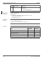
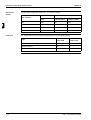
The table below contains the electrical specifications.
Specification
Unit
RP71L7V1
RP71L7W1
Phase
1~
3N~
Voltage
230 V
400 V
Frequency
50 Hz
No. of wire connections
3 wires for power supply
(including earth wire)
5 wires for power supply
(including earth wire)
4 wires for connection with indoor (including earth wire
Compressor
Fan motor
1–48
Power supply intake
Outdoor unit only
Phase
1~
3~
Voltage
230 V
400 V
Starting method
Direct
No. x motor output
1 x 2200 W
Phase
1~
Voltage
230 V
No. of motors x output
1 x 65W
Part 1 – System Outline
ESIE03–01
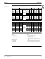
Electrical Data
Specifications
1
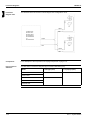
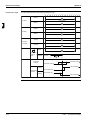
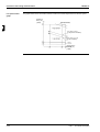
The table below contains the electrical specifications.
Unit combination
Power supply
Indoor unit
Outdoor unit
Hz-Volts
FHYCP71
RP71L7V1
FUYP71
RP71L7V1
Compressor
MCA
TOCA
MFA
50-230
15.1
23.2
50-230
15.0
23.2
FHYP71
RP71L7V1
50-230
FHYKP71
RP71L7V1
50-230
FAYP71
RP71L7V1
Voltage range
LRA
RLA
32
72
32
72
OFM
IFM
kW
FLA
kW
11.1
0.065
0.6
0.045
FLA
0.6
11.0
0.065
0.6
0.045
0.6
0.6
15.0
23.2
32
72
11.0
0.065
0.6
0.062
14.6
23.1
32
72
10.8
0.065
0.6
0.045
0.5
50-230
14.5
22.9
32
72
10.9
0.065
0.6
0.046
0.3
0.9
Max.50Hz-264V
Min.50Hz-198V
FHYBP71
RP71L7V1
50-230
15.1
23.5
32
72
10.9
0.065
0.6
0.125
FDYMP71
RP71L7V1
50-230
15.1
23.5
32
72
10.9
0.065
0.6
0.125
0.9
FHYCP71
RP71L7W1
50-400/230
6.6
11.2
16
37
4.3
0.065
0.6
0.045
0.6
FUYP71
RP71L7W1
50-400/230
6.6
11.2
16
37
4.3
0.065
0.6
0.045
0.6
FHYP71
RP71L7W1
50-400/230
6.6
11.2
16
37
4.3
0.065
0.6
0.062
0.6
FHYKP71
RP71L7W1
50-400/230
6.4
11.1
16
37
4.2
0.065
0.6
0.045
0.5
Max.50Hz440/253V
Min.50Hz360/197V
FAYP71
RP71L7W1
50-400/230
6.3
10.9
16
37
4.3
0.065
0.6
0.046
0.3
FHYBP71
RP71L7W1
50-400/230
6.8
11.5
16
37
4.2
0.065
0.6
0.125
0.9
FDYMP71
RP71L7W1
50-400/230
6.8
11.5
16
37
4.2
0.065
0.6
0.125
0.9
4
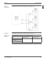
Symbols:
Notes:
MCA: Min. Circuit Amps
TOCA: Total Over-current Amps
1. RLA is based on the following conditions:
Indoor temp.: 27°CDB/19.5°CWB
Outdoor temp. : 35°CDB.
MFA: Max. Fuse Amps (see note 7)
2. TOCA means the total value of each OC set.
LRA : Locked Rotor Amps
OFM : Outdoor Fan Motor
3. Voltage range
Units are suitable for use on electrical systems where voltage
supplied to unit terminals is not below or above listed operation range
limits.
IFM : Indoor Fan Motor
4. Maximum allowable voltage unbalance between phases is 2%.
FLA : Full Load Amps
5. MCA/MFA
MCA = 1.25 x RLA + all FLA, MFA = < 2.25 x RLA + all FLA
(next lower standard fuse rating Min. 16A).
RLA : Rated Load Amps
kW : Fan Motor Rated Output
6. Select wire size based on the larger value of MCA or TOCA.
7. Instead of fuse, use circuit breaker.
Part 1 – System Outline
3
1–49
5
Specifications
11
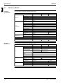
3.3
ESIE03–01
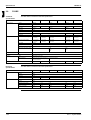
RP100 and RP125
Technical
specifications
The table below contains the technical specifications.
Specification
RP100L7V1
Rp100L7W1
Rp125L7W1
Model x No.
JT125FA-V1N x1
JT125FA-YE x 1
JT160FA-YE x 1
Type
Hermetically sealed scroll type
Crankcase heater
—
Refrigerant oil type
DAPHNE FVC68D
Speed
rpm
Oil charge
1500 cc
Length
859 mm
Compressor
3
4
Rows x stages x fin pitch
2 X 52 X 2.0 mm
No of passes
10
Outdoor
Face area
0.983 m²
Heat exchanger
Tube type
HI-XSS Cooling tube
Fin type
Non sym. waffle louvre
Empty tubeplate hole
0
Fan
No of fans
1
2
Nominal air flow (230V) cooling
55 m³/min
89 m³/min
Fan motor model
P47L11S
P47L11S x 2
Fan speed
3 steps
Type
R407C
Charge
3.7 kg
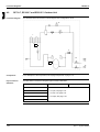
Refrigerant circuit
5
Electrical
specifications
Safety and functional devices
See page 1–63 and 3–19
Heat insulation
Both liquid and gas pipes
Weight
100 kg
99 kg
104 kg
Rp125L7W1
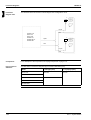
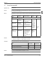
The table below contains the electrical specifications.
Specification
RP100L7V1
Rp100L7W1
Phase
1~
3N~
Voltage
230 V
400 V
Frequency
50 Hz
No. of wire connections
3 wires for power supply
(including earth wire)
Unit
5 wires for power supply
(including earth wire)
4 wires for connection with indoor (including earth wire)
Nominal running current
See electrical data
(cooling)
Max. running current
Compressor
Fan motor
1–50
See electrical data
Power supply intake
Outdoor unit only
Phase
1~
3~
Voltage
230 V
400 V
Starting method
Direct
No. x motor output
1 x 3000 W
Phase
1~
Voltage
230 V
No. of motors x output
90 W
1 x 3750 W
85 +65 W
Part 1 – System Outline
ESIE03–01
Electrical Data
Specifications
1
The table below contains the electrical specifications.
Unit combination
Power supply
Indoor unit
Outdoor unit
Hz-Volts
FHYCP100
RP100L7V1
FUYP100
Voltage range
Compressor
MCA
TOCA
MFA
50-230
22.7
34.8
RP100L7V1
50-230
22.4
FHYP100
RP100L7V1
50-230
FAYP100
RP100L7V1
50-230
Max.50Hz-264V
Min.50Hz-198V
LRA
RLA
40
97
34.8
40
22.5
34.5
21.7
34.2
OFM
IFM
kW
FLA
kW
FLA
16.7
0.090
0.8
0.090
1.0
97
16.5
0.090
0.8
0.090
1.0
40
97
16.8
0.090
0.8
0.130
0.7
40
97
16.4
0.090
0.8
0.049
0.4
1.0
FHYBP100
RP100L7V1
50-230
22.6
34.8
40
97
16.6
0.090
0.8
0.135
FDYMP100
RP100L7V1
50-230
22.4
34.8
40
97
16.5
0.090
0.8
0.135
1.0
FHYCP100
RP100L7W1
50-400/230
9.2
11.8
16
47
5.9
0.090
0.8
0.090
1.0
FUYP100
RP100L7W1
50-400/230
9.4
11.8
16
47
6.1
0.090
0.8
0.090
1.0
FHYP100
RP100L7W1
50-400/230
9.3
11.5
16
47
6.2
0.090
0.8
0.130
0.7
FAYP100
RP100L7W1
50-400/230
8.7
11.2
16
47
6.0
0.090
0.8
0.049
0.4
FHYBP100
RP100L7W1
50-400/230
9.3
11.8
16
47
6.0
0.090
0.8
0.135
1.0
FDYMP100
RP100L7W1
50-400/230
9.4
11.8
16
47
6.1
0.090
0.8
0.135
1.0
Unit combination
Max.50Hz440/253V
Min.50Hz360/197V
Power supply
Voltage range
Compressor
OFM
IFM
Indoor unit
Outdoor unit
Hz-Volts
MCA
TOCA
MFA
LRA
RLA
kW
FLA
kW
FLA
FHYCP125
RP125L7W1
50-400/230
11.6
15.3
20
59
7.4
0.065+
0.085
0.6+
07
0.09
1.0
FUYP125
RP125L7W1
50-400/230
11.6
15.3
20
59
7.4
0.065+
0.085
0.6+
0.7
0.09
1.0
FHYP125
RP125L7W1
50-400/230
11.4
15.0
20
59
7.5
0.065+
0.085
0.6+
0.7
0.13
0.7
FHYBP125
RP125L7W1
50-400/230
12.1
15.7
20
59
7.5
0.065+
0.085
0.6+
0.7
0.225
1.4
FDYMP125
RP125L7W1
50-400/230
12.1
15.7
20
59
7.5
0.065+
0.085
0.6+
0.7
0.225
1.4
FDYP125
RP125L7W1
50-400/230
14.9
18.5
20
59
7.5
0.065+
0.085
0.6+
0.7
0.5
4.2
Max.50Hz440/253V
Min.50Hz360/197V
Symbols:
Notes:
MCA: Min. Circuit Amps
TOCA: Total Over-current Amps
1. RLA is based on the following conditions:
Indoor temp.: 27°CDB/19.5°CWB
Outdoor temp. : 35°CDB.
MFA: Max. Fuse Amps (see note 7)
2. TOCA means the total value of each OC set.
LRA : Locked Rotor Amps
OFM : Outdoor Fan Motor
3. Voltage range
Units are suitable for use on electrical systems where voltage
supplied to unit terminals is not below or above listed operation range
limits.
IFM : Indoor Fan Motor
4. Maximum allowable voltage unbalance between phases is 2%.
FLA : Full Load Amps
5. MCA/MFA
MCA = 1.25 x RLA + all FLA, MFA = < 2.25 x RLA + all FLA
(next lower standard fuse rating Min. 16A).
RLA : Rated Load Amps
kW : Fan Motor Rated Output
6. Select wire size based on the larger value of MCA or TOCA.
7. Instead of fuse, use circuit breaker.
Part 1 – System Outline
1–51
3
4
5
Specifications
11
3.4
ESIE03–01
RYP71, RYP100 and RYP125
Technical
The table below contains the technical specifications.
specifications
Specification
Compressor
3
RYP71L7W1
RYP100L7V1
RYP100L7W1
RYP125L7W1
JT90FA-V1N x 1
JT90FA-YE x 1
JT125FA-V1N x 1
JT125FA-YE x 1
JT160FA-YE x 1
Type
Hermetically sealed scroll type
Crankcase heater
—
Refrigerant oil type
DAPHNE FVC68D
No. x motor output
1 x 2200 W
Speed
—
Oil charge
1200 cc
Length
859 mm
1 x 3000 W
1 x 3750 W
1500 cc
Rows x stages x fin pitch
2 x 34 x 2.0 mm
No of passes
6
10
Outdoor
Face area
0.364 m²
0.983 m²
Heat exchanger
Tube type
HI-XSS Cooling tube
Fin type
Non sym. waffle louvre
Empty tubeplate hole
0
No. of fans
1
Nominal air flow (230 V) cooling
48 m³/min
55 m³/min
89 m³/min
Nominal air flow (230 V) Heating
43 m³/min
50 m³/min
80 m³/min
4
Fan
5
RYP71L7V1
Model x No.
Fan motor model
P47L11S
Fan speed
3 steps
Type
R407C
Charge
2.8 kg
2 x 52 x 2.0 mm
2
P47L11S x 2
Refrigerant circuit
Safety and functional devices
3.7 kg
See page 1–63 and 3–19
Heat insulation
Both liquid and gas pipes
Weight
80 kg
Electrical
specifications
Compressor
Fan motor
1–52
102 kg
101 kg
106 kg
RYP125L7W1
The table below contains the electrical specifications.
Specification
Unit
79 kg
RYP71L7V1
RYP71L7W1
RYP100L7V1
RYP100L7W1
Phase
1~
3N~
1~
3N~
3N~
Voltage
230 V
400 V
230 V
400 V
400 V
Frequency
50 Hz
No. of wire connections
3 wires for power
5 wires for power
supply
supply
(including earth wire) (including earth wire)
3 wires for power
supply
(including earth wire)
5 wires for power
supply
(including earth wire)
5 wires for power
supply
(including earth wire)
4 wires for connec4 wires for connection with indoor
tion with indoor
(including earth wire) (including earth wire)
4 wires for connection with indoor
(including earth wire)
4 wires for connection with indoor
(including earth wire)
4 wires for connection with indoor
(including earth wire)
Power supply intake
Outdoor unit only
Phase
1~
3~
1~
3~
Voltage
230 V
400 V
230 V
400 V
Starting method
Direct
No. x motor output
1 x 2200 W
Phase
1~
Voltage
230 V
No. of motors x output
1 x 65 W
1 x 3000 W
1 x 3750 W
90 W
85 + 65 W
Part 1 – System Outline
ESIE03–01
Electrical Data
Specifications
Unit combination
Power supply
Indoor unit
Outdoor unit
Hz-Volts
FHYCP71
RYP71L7V1
FUYP71
RYP71L7V1
TOCA
MFA
50-230
15.1
23.2
50-230
14.7
23.2
FHYP71
RYP71L7V1
50-230
FHYKP71
RYP71L7V1
50-230
FAYP71
RYP71L7V1
Voltage range
Compressor
MCA
LRA
RLA
32
72
32
72
OFM
IFM
kW
FLA
kW
11.1
0.065
0.6
0.045
FLA
0.6
10.8
0.065
0.6
0.045
0.6
0.6
15.6
23.2
32
72
11.5
0.065
0.6
0.062
14.4
23.1
32
72
10.6
0.065
0.6
0.045
0.5
50-230
14.3
22.9
32
72
10.7
0.065
0.6
0.046
0.3
0.9
Max.50Hz-264V
Min.50Hz-198V
FHYBP71
RYP71L7V1
50-230
14.8
23.5
32
72
10.6
0.065
0.6
0.125
FDYMP71
RYP71L7V1
50-230
14.8
23.5
32
72
10.6
0.065
0.6
0.125
0.9
FHYCP71
RYP71L7W1
50-400/230
6.6
11.2
16
37
4.3
0.065
0.6
0.045
0.6
FUYP71
RYP71L7W1
50-400/230
6.5
11.2
16
37
4.2
0.065
0.6
0.045
0.6
FHYP71
RYP71L7W1
50-400/230
6.7
11.2
16
37
4.4
0.065
0.6
0.062
0.6
FHYKP71
RYP71L7W1
50-400/230
6.4
11.1
16
37
4.2
0.065
0.6
0.045
0.5
Max.50Hz440/253V
Min.50Hz360/197V
FAYP71
RYP71L7W1
50-400/230
6.2
10.9
16
37
4.2
0.065
0.6
0.046
0.3
FHYBP71
RYP71L7W1
50-400/230
6.8
11.5
16
37
4.2
0.065
0.6
0.125
0.9
FDYMP71
RYP71L7W1
50-400/230
6.8
11.5
16
37
4.2
0.065
0.6
0.125
0.9
Unit combination
Part 1 – System Outline
1
The table below contains the electrical specifications.
Power supply
Voltage range
Compressor
OFM
4
IFM
Indoor unit
Outdoor unit
Hz-Volts
MCA
TOCA
MFA
LRA
RLA
kW
FLA
kW
FLA
FHYCP100
RYP100L7V1
50-230
22.7
34.8
40
97
16.7
0.090
0.8
0.090
1.0
FUYP100
RYP100L7V1
50-230
22.3
34.8
40
97
16.4
0.090
0.8
0.090
1.0
FHYP100
RYP100L7V1
50-230
22.5
34.5
40
97
16.8
0.090
0.8
0.130
0.7
FAYP100
RYP100L7V1
50-230
22.1
34.2
40
97
16.7
0.090
0.8
0.049
0.4
FHYBP100
RYP100L7V1
50-230
22.3
34.8
40
97
16.4
0.090
0.8
0.135
1.0
FDYMP100
RYP100L7V1
50-230
22.4
34.8
40
97
16.5
0.090
0.8
0.135
1.0
Max.50Hz-264V
Min.50Hz-198V
FHYCP100
RYP100L7W1
50-400/230
9.3
11.8
16
47
6.0
0.090
0.8
0.090
1.0
FUYP100
RYP100L7W1
50-400/230
9.3
11.8
16
47
6.0
0.090
0.8
0.090
1.0
FHYP100
RYP100L7W1
50-400/230
9.3
11.5
16
47
6.2
0.090
0.8
0.130
0.7
FAYP100
RYP100L7W1
50-400/230
8.8
11.2
16
47
6.1
0.090
0.8
0.049
0.4
FHYBP100
RYP100L7W1
50-400/230
9.3
11.8
16
47
6.0
0.090
0.8
0.135
1.0
FDYMP100
RYP100L7W1
50-400/230
9.4
11.8
16
47
6.1
0.090
0.8
0.135
1.0
Max.50Hz440/253V
Min.50Hz360/197V
3
1–53
5
Specifications
11
ESIE03–01
Unit combination
Power supply
Voltage range
Compressor
OFM
IFM
Indoor unit
Outdoor unit
Hz-Volts
MCA
TOCA
MFA
LRA
RLA
kW
FLA
kW
FLA
FHYCP125
RY(E)P125L7W1
50-400/230
12.2
15.3
20
59
7.9
0.065+
0.085
0.6+
07
0.09
1.0
FUYP125
RY(E)P125L7W1
50-400/230
11.4
15.3
20
59
7.3
0.065+
0.085
0.6+
0.7
0.09
1.0
FHYP125
RY(E)P125L7W1
50-400/230
12.1
15.0
20
59
8.1
0.065+
0.085
0.6+
0.7
0.13
0.7
FHYBP125
RY(E)P125L7W1
50-400/230
12.0
15.7
20
59
7.4
0.065+
0.085
0.6+
0.7
0.225
1.4
FDYMP125
RY(E)P125L7W1
50-400/230
12.0
15.7
20
59
7.4
0.065+
0.085
0.6+
0.7
0.225
1.4
FDYP125
RY(E)P125L7W1
50-400/230
14.8
18.5
20
59
7.4
0.065+
0.085
0.6+
0.7
0.5
4.2
Max.50Hz440/253V
Min.50Hz360/197V
3
4
Symbols:
Notes:
MCA: Min. Circuit Amps
TOCA: Total Over-current Amps
1. RLA is based on the following conditions:
Indoor temp.: 27°CDB/19.5°CWB
Outdoor temp. : 35°CDB.
MFA: Max. Fuse Amps (see note 7)
2. TOCA means the total value of each OC set.
LRA : Locked Rotor Amps
OFM : Outdoor Fan Motor
3. Voltage range
Units are suitable for use on electrical systems where voltage
supplied to unit terminals is not below or above listed operation range
limits.
IFM : Indoor Fan Motor
4. Maximum allowable voltage unbalance between phases is 2%.
FLA : Full Load Amps
5. MCA/MFA
MCA = 1.25 x RLA + all FLA, MFA = < 2.25 x RLA + all FLA
(next lower standard fuse rating Min. 16A).
RLA : Rated Load Amps
kW : Fan Motor Rated Output
5
6. Select wire size based on the larger value of MCA or TOCA.
7. Instead of fuse, use circuit breaker.
1–54
Part 1 – System Outline
ESIE03–01
3.5
Specifications
FHYCP
1
Technical
specifications
The table below contains the technical specifications.
Specification
Heat exchanger
Fan
FHYCP35B7V1
Rows x stages x fin pitch
FHYCP71B7V1
FHYCP100B7V1
Face area
0.331 m²
0.497 m²
Tube type
Hi-XA
FHYCP125B7V1
Fin type
Cross fin coil
Nominal air flow (cooling)
H: 14 m³/min
H: 15 m³/min
H: 18 m³/min
H: 28 m³/min
H: 31 m³/min
L: 10 m³/min
L: 11 m³/min
L: 14 m³/min
L: 21 m³/min
L: 24 m³/min
H: 14 m³/min
H: 15 m³/min
H: 18 m³/min
H: 28 m³/min
H: 31 m³/min
L: 10 m³/min
L: 11 m³/min
L: 14 m³/min
L: 21 m³/min
L: 24 m³/min
Fan motor model
QTS46B14M
Fan speed
2 steps
QTS46A17M
Fan type
Turbo fan
Drive
Direct drive
Type
R407C
Filter class
Resin net (mold resistant)
Safety and functional devices
Air filter
FHYCP60B7V1
2 x 12 x 1.5 mm
Nominal air flow (heating)
Refrigerant circuit
FHYCP45B7V1
2 x 8 x 1.5 mm
See page 1–63 and 3–18
4
Max. temperature
Cleaning
Temperature control
Insulation
3
Computerized control
Heat
Foamed polystyrene
Sound absorbing
Weight
Electrical
specifications
Fan motor
Unit: 27 kg
Decoration panel: 5 kg
Decoration panel: 5 kg
5
The table below contains the electrical specifications.
Specification
Unit
Unit: 23 kg
FHYCP35B7V1
Phase
1~
Voltage
230 V
Frequency
50 Hz
FLA (Full Load Amps)
0.6 A
Power consumption
140 W
No. of motors x output
1 x 45 W
Part 1 – System Outline
FHYCP45B7V1
FHYCP60B7V1
FHYCP71B7V1
FHYCP100B7V1
FHYCP125B7V1
1.0 A
161 W
204 W
238 W
1 x 90 W
1–55
Specifications
11
3.6
ESIE03–01
FHYBP
Technical
specifications
The table below contains the technical specifications.
Specification
Heat exchanger
3
Fan
FHYBP35B7V1
Length
Rows x stages x fin pitch
3 x 14 x 1.75 mm
No. of passes
4
Face area
0.132 m²
Tube type
Hi-XA
Fin type
Fin Rhombus type
Empty tube hole
4
No. of fans
1
Nominal air flow (cooling)
H: 11.5 m³/min
L: 9 m³/min
Nominal air flow (heating)
4
FHYBP45B7V1
450 mm
6
FHYBP60B7V1
FHYBP71B7V1
FHYBP100B7V1
750 mm
1150 mm
7
10
0.221 m²
0.338 m²
0
FHYBP125B7V1
13
14
0
2
3
H: 14 m³/min
H: 19 m³/min
H: 27 m³/min
H: 35 m³/min
L: 10 m³/min
L: 14 m³/min
L: 20 m³/min
L: 24 m³/min
H: 11.5 m³/min
H: 14 m³/min
H: 19 m³/min
H: 27 m³/min
H: 35 m³/min
L: 9 m³/min
L: 10 m³/min
L: 14 m³/min
L: 20 m³/min
L: 24 m³/min
H: 88
H: 88
M: 49
M: 49
Fan speed
2 steps
Fan type
Sirocco fan
Drive
Direct drive
Static external pressure (50/60
Hz)
—
L: 20
Refrigerant circuit
Type
R407C
Heat
Both liquid and gas pipes
Sound absorbing
Flame and heat resistant foamed polyethylene, regular foamed polyethylene and foamed PU
Foamed polyurethane
30 kg
41 kg
Safety and functional devices
5
Insulation
See page 1–63 and 3–18
Weight
Electrical
specifications
Fan motor
1–56
51 kg
52 kg
FHYBP100B7V1
FHYBP125B7V1
The table below contains the electrical specifications.
Specification
Unit
31 kg
FHYBP35B7V1
Phase
1~
Voltage
230 V
Frequency
50 Hz
Recommended fuses
16 A
Phase
1~
Voltage
230 V
FHYBP45B7V1
FHYBP60B7V1
20 A
—
FHYBP71B7V1
Nominal running current
0.5 A
0.7 A
0.9 A
1.0 A
1.4 A
No. of motors x output
1 x 65 W
1 x 85 W
1 x 125 W
1 x 135 W
1 x 225 W
Power consumption
65 W
85 W
125 W
135 W
225 W
Part 1 – System Outline
ESIE03–01
3.7
Specifications
FDYP
Technical
specifications
1
The table below contains the technical specifications.
Specification
Heat exchanger
Fan
Refrigerant circuit
FDYP125B7V1
Rows x stages x fin pitch
0.338 m²
Tube type
Hi-XA
Fin type
MLH7 fin hydrophilia
Nominal air flow (cooling)
43 m³/min
Fan motor model
DPA216-178NB
Fan speed
3 steps
Drive
Direct drive
Static external pressure (50/60
Hz)
0-150 Pa
Type
R407C
Filter class
Eurovent 4/5 (EU2), EN
779 5G2)
Max. temperature
100°C
Cleaning
Hot water 30-40°C or
compressed air
Safety and functional devices
Air filter
Flame and heat resistant
foamed felt
59 kg
5
The table below contains the electrical specifications.
Specification
Unit
Fan motor
Part 1 – System Outline
4
Computerized control
Sound absorbing
Weight
Electrical
specifications
3
See page 1–63 and 3–18
Temperature control
Insulation
3 x 14 x 1.75 mm
Face area
FDYP125B7V1
Phase
1~
Voltage
230 V
Frequency
50 Hz
No. of motors x output
500 W
1–57
Specifications
11
3.8
ESIE03–01
FHYP
Technical
specifications
The table below contains the technical specifications.
Specification
Heat exchanger
3
4
Fan
FHYP35BV1
Length
2 x 12 x 1.75 mm
No. of passes
6
Face area
0.182 m²
Tube type
N-hiX tubes
Fin type
Cross fin coil (multi louvre fins)
Fan motor
1–58
3 x 12 x 1.75 mm
11
0.233 m²
0.293 m²
0.341 m²
0
H: 16m³/min
H: 17 m³/min
H: 24 m³/min
H: 30 m³/min
L: 10 m³/min
L: 13 m³/min
L: 14 m³/min
L: 20 m³/min
L: 25 m³/min
H: 13 m³/min
H: 16 m³/min
H: 17 m³/min
H: 24 m³/min
H: 30 m³/min
L: 10 m³/min
L: 13 m³/min
L: 14 m³/min
L: 20 m³/min
L: 25 m³/min
Fan motor model
3D12K1AA1
4D12K1AA1
3D12K2AA1
4D12K2AA1
Fan speed
2 steps
27 kg
32 kg
35 kg
FHYP60BV1
FHYP71BV1
FHYP100BV1
FHYP125BV1
115 W
117 W
135 W
144 W
Fan type
Sirroco fan
Type
R407C
Heat
Foamed polystyrene / foamed polyethylene
See page 1–63 and 3–18
Foamed polyurethane / glass wool
23 kg
24 kg
26 kg
The table below contains the electrical specifications.
Specification
Unit
FHYP125BV1
1352 mm
H: 13 m³/min
Sound absorbing
Electrical
specifications
FHYP100BV1
1162 mm
Nominal air flow (cooling)
Weight
5
FHYP71BV1
Empty tube hole
Safety and functional devices
Insulation
FHYP60BV1
922 mm
Rows x stages x fin pitch
Nominal air flow (heating)
Refrigerant circuit
FHYP45BV1
722 mm
FHYP35BV1
Phase
1~
Voltage
230 V
Frequency
50 Hz
Phase
1~
Voltage
230 V
Power consumption
111 W
FLA (Full Load Amps)
0.6 A
No. of motors x output
3 x 62 W
FHYP45BV1
0.7 A
4 x 62 W
3 x 130 W
4 x 130 W
Part 1 – System Outline
ESIE03–01
3.9
Specifications
FUYP
Technical
specifications
1
The table below contains the technical specifications.
Specification
Heat exchanger
Fan
FUYP71BV17
Length
Rows x stages x fin pitch
3 x 6 x 1.8 mm
No. of passes
8
Face area
0.265 m²
Tube type
N-hiX tubes
3 x 8 x 1.8 mm
12
0.353 m²
Cross fin coil (multi louvre fins)
Empty tube hole
0
4
0
Nominal air flow (cooling)
H: 19 m³/min
H: 29 m³/min
H: 32 m³/min
L: 14 m³/min
L: 21 m³/min
L: 23 m³/min
H: 19 m³/min
H: 29 m³/min
H: 32 m³/min
L: 14 m³/min
L: 21 m³/min
L: 23 m³/min
Fan motor model
QTS48A10M
QTS50B15M
Fan speed
2 steps
Fan type
Turbo fan
Type
R407C
Safety and functional devices
See page 1–63 and 3–18
Air filter
Resin net (with mold resistant)
Insulation
FUYP125BV17
Fin type
Nominal air flow (heating)
Refrigerant circuit
FUYP100BV17
2101 mm
Heat
3
4
Heat resistant foamed polyethylene
Regular foamed polyethylene
Weight
Electrical
specifications
25 kg
5
The table below contains the electrical specifications.
Specification
Unit
Fan motor
FUYP71BV17
Phase
1~
Voltage
230 V
Frequency
50 Hz
Phase
1~
Voltage
230 V
Power consumption
Part 1 – System Outline
31 kg
Cooling: 180 W
FUYP100BV17
FUYP125BV17
Cooling: 289 W
Heating: 160 W
Heating: 269 W
FLA (Full Load Amps)
0.6 A
1.0 A
No. of motors x output
1 x 45 W
1 x 90 W
1–59
Specifications
11
3.10
ESIE03–01
FAYP and FHYKP
Technical
specifications
The table below contains the technical specifications.
Specification
Heat exchanger
3
Fan
Length
5
Electrical
specifications
Fan motor
1–60
FHYKP60BV1
2 x 12 x 1.4 mm
2 x 11 x 1.75 mm
5
9
Face area
0.289 m²
0.332 m²
0.186 m²
0.226 m²
Tube type
Hi-XA tubes
N-hiX tubes
N-hiX tubes
Fin type
Cross fin coil (multi louvre fins)
Cross fin coil (multi louvre fins)
Empty tube hole
0
2
3
Nominal air flow (cooling)
H: 19 m³/min
H: 23 m³/min
H: 12 m³/min
H: 12 m³/min
H: 17 m³/min
L: 15 m³/min
L: 19 m³/min
L: 9 m³/min
L: 10 m³/min
L: 14 m³/min
H: 19 m³/min
H: 23 m³/min
H: 12 m³/min
H: 12 m³/min
H: 17 m³/min
L: 15 m³/min
L: 19 m³/min
L: 9 m³/min
L: 10 m³/min
L: 14 m³/min
QCL9686M
QCL1163MA and
QCL1163MAB
3D12H1AH1V1
3D12H1J1V1
4D12H1AG1V1
3 x 11 x 1.75 mm
Fan speed
2 steps
2 steps
Fan type
Cross flow fan
Sirocco fan
Type
R407C
R407C
See page 1–63 and 3–18
See page 1–63 and 3–18
Heat
Foamed polystyrene / foamed polyeth- Foamed polystyrene / foamed polyethylene
ylene
Model
—
13 kg
26 kg
30 kg
FHYKP71BV1
978 mm
9
31 kg
BYK45FJW1
33 kg
BYK71FJW1
Air filter
—
Resin net (with mold resistant)
Weight
—
8.5 kg
9.5 kg
The table below contains the electrical specifications.
Specification
Unit
FHYKP45BV1
2 x 16 x 1.4 mm
Weight
Decoration panel (option)
778 mm
4
Safety and functional devices
Insulation
FHYKP35BV1
1320 mm
No. of passes
Nominal air flow (heating)
Refrigerant circuit
FAYP100BV1
863 mm
Rows x stages x fin pitch
Fan motor model
4
FAYP71LV1
FAYP71LV1
FAYP100BV1
FHYKP35BV1
FHYKP45BV1
FHYKP60BV1
Cooling: 92 W
Cooling: 100 W
Cooling: 123 W
Heating: 59 W
Heating: 67 W
Heating: 90 W
Phase
1~
1~
Voltage
230 V
230 V
Frequency
50 Hz
50 Hz
Phase
1~
1~
Voltage
230 V
Power consumption
68 W
FHYKP71BV1
230 V
101 W
FLA (Full Load Amps)
0.4 A
0.4 A
0.2 A
0.3 A
0.5 A
No. of motors x output
1 x 43 W
1 x 49 W
1 x 20 W
1 x 25 W
1 x 45 W
Part 1 – System Outline
ESIE03–01
3.11
Specifications
FDYMP
Technical
specifications
1
The table below contains the technical specifications.
Specification
Heat exchanger
Fan
FDYMP71L7V1
Rows x stages x fin pitch
3 x 14 x 1.75 mm
No. of passes
7
13
Face area
0.226 m²
0.344 m²
Tube type
HI-XA Ø7
Fin type
Fin Rhombus type
Empty tube hole
0
No.of fans
2
Nominal air flow (cooling)
H: 19 m³/min
H: 27 m³/min
H: 35 m³/min
L: 14 m³/min
L: 20 m³/min
L: 24 m³/min
H: 19 m³/min
H: 27 m³/min
H: 35 m³/min
L: 14 m³/min
L: 20 m³/min
L: 24 m³/min
Fan motor model
—
Fan speed
3 steps
Fan type
Sirocco fan
Type
R407C
Safety and functional devices
See page 1–63 and 3–18
Air filter
Resin net
Insulation
Heat
Weight
Electrical
specifications
1.170 mm
3
3
4
Both liquid and gas pipes
38.1 kg
48.6 kg
5
The table below contains the electrical specifications.
Specification
Unit
Fan motor
Part 1 – System Outline
FDYMP125L7V1
0.770 mm
Nominal air flow (heating)
Refrigerant circuit
FDYMP100L7V1
Length
FDYMP71L7V1
Phase
1~
Voltage
230 V
Frequency
50 Hz
Phase
1~
Voltage
230 V
FDYMP100L7V1
FDYMP125L7V1
Power consumption
150 W
195 W
415 W
No. of motors x output
1 x 130 W
1 x 155 W
1 X 225 W
1–61
Specifications
ESIE03–01
11
3
4
5
1–62
Part 1 – System Outline
ESIE03–01
Functional Diagrams
Part 1
4
Functional Diagrams
4.1
What Is in This Chapter?
Introduction
Functional
diagrams
Part 1 – System Outline
This chapter contains the following information:
P
Functional diagrams
P
Pipe connection diameters.
1
3
This chapter contains the following functional diagrams:
Functional diagram
See page
4.2–RP71L7, RP100L7 and RP125L7: Outdoor Unit
1–64
4.3–RYP71L7, RYP100L7 and RYP125L7: Outdoor Unit
1–68
4.4–FHYBP, FHYCP, FUYP, FAYP, FDYP, FHYP, FHYKP and FDYMP
1–72
4.5–Piping Components
1–75
4
5
1–63
Functional Diagrams
11
4.2
ESIE03–01
RP71L7, RP100L7 and RP125L7: Outdoor Unit
Functional diagram
The illustration below shows the functional diagram of the refrigeration circuit.
18
8
7
6
10
3
R2T
4
8
2b
11
R1T
5
4
3
Components
For a description of the components, see ’Piping Components’ on page 1–75.
Pipe connection
diameters
The table below contains the refrigerant pipe connection diameters.
Model
∅ Gas pipe (flare)
Liquid
piping
12
Gas
piping
13
∅ Liquid pipe (flare)
RP71L7V1
RP71L7W1
P
For pair, see page 1-65.
RP100L7V1
P
For twin, see page 1-66.
RP100L7W1
P
For triple, see page 1-67.
RP125L7W1
1–64
Part 1 – System Outline
ESIE03–01
Functional
diagram: Pair
Functional Diagrams
1
The illustration below shows the functional diagram of the refrigeration circuit.
Outdoor unit:
RP71L7V1,
RP71L7W1,
RP100L7V1,
RP100L7W1
RP125L7W1
7
R2T
Liquid
8
3
Gas
Components
For a description of the components, see ’Piping Components’ on page 1–75.
Pipe connection
diameters
The table below contains the refrigerant pipe connection diameters (O.D.).
Model
∅ Gas pipe (flare)
∅ Liquid pipe (flare)
RP71L7V1
15.9 mm
9.5 mm
4
RP71L7W1
RP100L7V1
5
19.1 mm
RP100L7W1
RP125L7W1
Part 1 – System Outline
1–65
Functional Diagrams
11
Functional
diagram: Twin
ESIE03–01
The illustration below shows the functional diagram of the refrigeration circuit.
7
R2T
14
Liquid
Gas
Outdoor unit:
RP71L7V1,
RP71L7W1,
RP100L7V1,
RP100L7W1 or
RP125L7W1
3
7
Liquid
R2T
Gas
4
14
Liquid
Gas
5
Components
For a description of the components, see ’Piping Components’ on page 1–75.
Pipe connection
diameters
The table below contains the refrigerant pipe connection diameters (O.D.).
Model
∅ Gas pipe (flare)
∅ Liquid pipe (flare)
RP71L7V1
15.9 mm
9.5 mm
RP71L7V1
RP100L7V1
19.1 mm
RP100L7W1
RP125L7W1
1–66
Part 1 – System Outline
ESIE03–01
Functional
diagram: Triple
Functional Diagrams
1
The illustration below shows the functional diagram of the refrigeration circuit.
7
R2T
14
Liquid
Gas
7
Outdoor unit:
RP100L7V1,
RP100L7W1 or
RP125L7W1
3
R2T
Liquid
14
Liquid
4
Gas
Gas
7
R2T
5
14
Liquid
Gas
Components
For a description of the components, see ’Piping Components’ on page 1–75.
Pipe connection
diameters
The table below contains the refrigerant pipe connection diameters (O.D.).
Model
∅ Gas pipe (flare)
∅ Liquid pipe (flare)
RP100L7V1
19.1 mm
9.5 mm
RP100L7W1
RP125L7W1
Part 1 – System Outline
1–67
Functional Diagrams
11
4.3
ESIE03–01
RYP71L7, RYP100L7 and RYP125L7: Outdoor Unit
Functional diagram
The illustration below shows the functional diagram of the refrigeration circuit.
8
6
18
15a
15a
7
8
15a
15a
3
21
10
4
16
8
13
12
5
Gas
Liquid
piping piping
2b
11
3
4
Components
For a description of the components, see ’Piping Components’ on page 1–75.
Pipe connection
diameters
The table below contains the refrigerant pipe connection diameters.
Model
∅ Gas pipe (flare)
∅ Liquid pipe (flare)
RYP71L7V1
RYP71L7W1
P
For pair, see page 1-69.
RYP100L7V1
P
For twin, see page 1-70.
RYP100L7W1
P
For triple, see page 1-71.
RYP125L7W1
1–68
Part 1 – System Outline
ESIE03–01
Functional
diagram: Pair
Functional Diagrams
1
The illustration below shows the functional diagram of the refrigeration circuit.
7
Outdoor unit:
RYP71L7V1,
RYP71L7W1,
RYP100L7V1,
RYP100L7W1
or
RYP125L7W1
Liquid
8
Gas
3
Components
For a description of the components, see ’Piping Components’ on page 1–75.
Pipe connection
diameters
The table below contains the refrigerant pipe connection diameters (O.D.).
Model
∅ Gas pipe (flare)
∅ Liquid pipe (flare)
RYP71L7V1
15.9 mm
9.5 mm
4
5
RYP71L7W1
RYP100L7V1
19.1 mm
RYP100L7W1
RYP125L7W1
Part 1 – System Outline
1–69
Functional Diagrams
11
Functional
diagram: Twin
ESIE03–01
The illustration below shows the functional diagram of the refrigeration circuit.
7
14
Liquid
Outdoor unit:
RYP71L7V1,
RYP71L7W1,
RYP100L7V1,
RYP100L7W1
or
RYP125L7W1
3
4
Gas
7
Liquid
Gas
14
Liquid
Gas
5
Components
For a description of the components, see ’Piping Components’ on page 1–75.
Pipe connection
diameters
The table below contains the refrigerant pipe connection diameters (O.D.).
Model
∅ Gas pipe (flare)
∅ Liquid pipe (flare)
RYP71L7V1
15.9 mm
9.5 mm
RYP71L7W1
RYP100L7V1
19.1 mm
RYP100L7W1
RYP125L7W1
1–70
Part 1 – System Outline
ESIE03–01
Functional
diagram: Triple
Functional Diagrams
1
The illustration below shows the functional diagram of the refrigeration circuit.
7
14
Liquid
Gas
7
Outdoor unit:
RYP100L7V1,
RYP100L7W1
or
RYP125L7W1
3
Liquid
14
Liquid
4
Gas
Gas
7
5
14
Liquid
Gas
Components
For a description of the components, see ’Piping Components’ on page 1–75.
Pipe connection
diameters
The table below contains the refrigerant pipe connection diameters (O.D.).
Model
∅ Gas pipe (flare)
∅ Liquid pipe (flare)
RYP100L7V1
19.1 mm
9.5 mm
RYP100L7W1
RYP125L7W1
Part 1 – System Outline
1–71
Functional Diagrams
11
4.4
ESIE03–01
FHYBP, FHYCP, FUYP, FAYP, FDYP, FHYP, FHYKP and FDYMP
Functional diagram
The illustration below shows the functional diagram of the refrigeration circuit.
7
3
Cooling
1a
8
Heating
1a
4
5
Components
For a description of the components, see ’Piping Components’ on page 1–75.
Pipe connection
diameters
The table below contains the refrigerant pipe connection diameters.
Model
∅ Gas pipe (flare)
∅ Liquid pipe (flare)
FHYBP35B7V1
12.70 mm
6.35 mm
FHYBP45B7V1
15.90 mm
FHYBP60B7V1
9.52 mm
FHYBP71B7V1
FHYBP100B7V1
19.05
FHYBP125B7V1
FHYCP35B7V1
12.70 mm
FHYCP45B7V1
15.90 mm
FHYCP60B7V1
6.35 mm
9.52 mm
FHYCP71B7V1
FHYCP100B7V1
19.05 mm
FHYCP125B7V1
FUYP71BV17
15.90 mm
FUYP100BV17
19.05 mm
9.52 mm
FUYP125BV17
1–72
FAYP71BV1
15.90 mm
FAYP100BV1
19.05 mm
FDYP125B7V1
19.05 mm
9.52 mm
9.52 mm
Part 1 – System Outline
ESIE03–01
Functional Diagrams
Model
∅ Gas pipe (flare)
∅ Liquid pipe (flare)
FHYP35BV1
12.70 mm
6.35 mm
15.90 mm
9.52 mm
1
FHYP45BV1
FHYP60BV1
FHYP71BV1
FHYP100BV1
19.05 mm
FHYP125BV1
FHYKP35BV1
12.70 mm
6.35 mm
15.90 mm
9.52 mm
FDYMP71L7V1
12.0~12.4 mm
18.6~19.0 mm
FDYMP100L7V1
12.0~12.4 mm
22.9~23.3 mm
3
FHYKP45BV1
FHYKP60BV1
FHYKP71BV1
4
FDYMP125L7V1
5
Part 1 – System Outline
1–73
Functional Diagrams
ESIE03–01
11
3
4
5
1–74
Part 1 – System Outline
ESIE03–01
4.5
Components
The table below contains the different components of the functional diagrams.
No.
Component
Function / remark
1a
Flare connection
See pipe connection diameter.
1b
Flange connection
2a
Liquid stop valve
2b
Liquid stop valve
with service port
3
Gas stop valve with
service port
The gas stop valve is used as shut-off valve in case of a pump-down.
4
Compressor
The compressor can restart after 3 min from last stop.
5a
Capillary tube
The capillary tube allows pressure equalization during a compressor OFF-cycle.
5b
The liquid stop valve is used as shut-off valve in case of a pump-down.
The capillary tube expands the liquid to enable evaporation in the evaporator.
6
Electronic expansion valve
The expansion valve expands the liquid to enable evaporation in the evaporator. The opening
degree is controlled to obtain the optimum discharge temperature.
7
Heat exchanger
The heat exchanger is of the multi louvre fin type. Hi-X -tubes and coated waffle louvre fins are
used.
8
Filter
The filter is used to collect impurities, which may enter the system during installation and is also
used to avoid blockage of the capillaries and other fine mechanical parts of the unit.
9
Accumulator
The accumulator is used to separate the gas from the liquid in order to protect the compressor
against liquid pumping.
10
Liquid receiver
The liquid receiver is used to make sure only completely liquefied refrigerant is sent to the expansion valve. It is also used as a container in which surplus refrigerant is stored.
11
Check valve with
service port
The check valve allows you to connect a gauge.
12
Low-pressure switch
The low-pressure switch stops the operation of the unit when the pressure becomes abnormally
low.
13
High-pressure
switch
The high-pressure switch stops the operation of the unit when the pressure becomes abnormally
high.
14
Propeller fan and fan
motor
The propeller fan creates air displacement across the heat exhanger.
15a
One-way valve
The one-way valve is used to force the refrigerant liquid to flow through the receiver and the
expansion valve in the same direction both in cooling and heating.
15b
16
The one-way valve is used to release overpressure in the liquid receiver during stand-still.
4-way valve
The 4-way valve is used to select refrigerant flow in cooling or heating mode.
(reversing solenoid
valve)
When the 4-way valve switches from ON to OFF, a timer starts counting up to 150 as soon as the
cooling or defrosting operation is stopped. This delay time is to eliminate the switching sound.
17
Muffler
The muffler is used to absorb the refrigerant noise from the compressor.
18
Solenoid valve
P
Y1S: Capacity control solenoid valve
P
Y3S: Liquid injection solenoid valve
P
SV: Solenoid valve (Purge liquid receiver)
P
R1T: Air thermistor
P
R2T: Coil thermistor
P
R3T: Discharge pipe thermistor
19
20
Part 1 – System Outline
Part 1
Piping Components
Thermistor
Strainer
1–75
ESIE03–01
1–76
Part 1 – System Outline
ESIE03–01
Switch Box Layout
Part 1
5
Switch Box Layout
5.1
What Is in This Chapter?
Introduction
This chapter shows the switch box components.
Outdoor units
This chapter contains the following switch box layouts:
Indoor units
Part 1 – System Outline
1
3
Switch box layout
See page
5.2–R(Y)P71-100L7V1
1–78
5.3–R(Y)P71~100L7W1
1–79
5.4–R(Y)P125L7W1
1–80
4
This chapter contains the following switch box layouts:
Switch box layout
See page
5.5–FHYCP35B7V1, FHYCP45B7V1, FHYCP60B7V1, FHYCP71B7V1,
FHYCP100B7V1 and FHYCP125B7V1
1–81
5.6–FHYBP35B7V1, FHYBP45B7V1, FHYBP60B7V1, FHYBP71B7V1,
FHYBP100B7V1 and FHYBP125B7V1
1–82
5.7–FDYP125B7V1
1–83
5.8–FHYP35BV1, FHYP45BV1, FHYP60BV1, FHYP71BV1, FHYP100BV1 and
FHYP125BV1
1–84
5.9–FUYP71BV17, FUYP100BV17 and FUYP125BV17
1–85
5.10–FAYP100BV1
1–86
5.11–FAYP71LV1
1–87
5.12–FHYKP35BV1, FHYKP45BV1, FHYKP60BV1 and FHYKP71BV1
1–88
5.13–FDYMP71~125L7V1
1–89
1–77
5
Switch Box Layout
11
5.2
ESIE03–01
R(Y)P71-100L7V1
Switch box
The illustration below shows the switch box layout.
-
-
-
-
-
3
4
5
-
Components
1–78
-
-
The table below contains the components of the switch box.
Symbol
Component
T1R
Transformer
K1S
Starting contactor
C1R
Fan motor capacitor
K1M
Magnetic contactor
F1C
Overcurrent relay
X1M
Terminal strip
PCB1
Printed circuit board
PCB2
Printed circuit board (interlock PCB)
Part 1 – System Outline
ESIE03–01
5.3
Switch Box Layout
R(Y)P71~100L7W1
Switch box
1
The illustration below shows the switch box layout.
X1M
PCB1
PCB2
3
4
5
F1C
Components
Part 1 – System Outline
K1M
C1R
T1R
The table below contains the components of the switch box.
Symbol
Component
X1M
Terminal strip
PCB1
Printed circuit board
PCB2
Printed circuit board (interlock PCB)
T1R
Transformer
C1R
Fan motor capacitor
K1M
Magnetic contactor
F1C
Overcurrent relay
1–79
Switch Box Layout
11
5.4
ESIE03–01
R(Y)P125L7W1
Switch box
The illustration below shows the switch box layout.
X1M
PCB2
PCB1
3
4
5
F1C
Components
1–80
K1M
C2R
C1R
T1R
The table below contains the components of the switch box.
Symbol
Component
X1M
Terminal strip
PCB1
Printed circuit board
PCB2
Printed circuit board (interlock PCB)
T1R
Transformer
C1R
Fan motor capacitor 1
C2R
Fan motor capacitor 2
K1M
Magnetic contactor
F1C
Overcurrent relay
Part 1 – System Outline
ESIE03–01
5.5
Switch Box Layout
FHYCP35B7V1, FHYCP45B7V1, FHYCP60B7V1,
FHYCP71B7V1, FHYCP100B7V1 and FHYCP125B7V1
Switch box
1
The illustration below shows the switch box layout.
T1R
PCB1
C1R
3
4
X1M
Components
Part 1 – System Outline
X2M
5
The table below contains the components of the switch box.
Symbol
Component
T1R
Transformer
PCB1
Printed circuit board
C1R
Fan motor capacitor
X2M
Terminal strip (interconnection wiring)
X1M
Terminal strip (for remote controller P1/P2)
1–81
Switch Box Layout
11
5.6
ESIE03–01
FHYBP35B7V1, FHYBP45B7V1, FHYBP60B7V1, FHYBP71B7V1, FHYBP100B7V1
and FHYBP125B7V1
Switch box
The illustration below shows the switch box layout.
C1R
PCB1
3
4
5
T1R
Components
1–82
X1M
X2M
The table below contains the components of the switch box.
Symbol
Component
PCB1
Printed circuit board
C1R
Fan motor capacitor
X2M
Terminal strip (interconnection wiring)
X1M
Terminal strip (for remote controller P1/P2)
T1R
Transformer
Part 1 – System Outline
ESIE03–01
5.7
Switch Box Layout
FDYP125B7V1
Switch box
1
The illustration below shows the switch box layout.
PCB1
PCB2
K1F
3
4
5
T1R
Components
Part 1 – System Outline
X1M
The table below contains the components of the switch box.
Symbol
Component
PCB1
Printed circuit board
PCB2
Printed circuit board (interlock PCB)
K1F
Magnetic contactor
X1M
Terminal strip
T1R
Transformer
1–83
Switch Box Layout
11
5.8
ESIE03–01
FHYP35BV1, FHYP45BV1, FHYP60BV1, FHYP71BV1,
FHYP100BV1 and FHYP125BV1
Switch box
The illustration below shows the switch box layout.
PCB1
C1R
T1R
3
4
R1T
Components
5
1–84
X1M
X2M
The table below contains the components of the switch box.
Symbol
Component
PCB1
Printed circuit board
C1R
Fan motor capacitor
T1R
Transformer
X2M
Terminal strip (interconnection wiring)
X1M
Terminal strip (for remote controller P1/P2)
R1T
Air thermistor
Part 1 – System Outline
ESIE03–01
5.9
Switch Box Layout
FUYP71BV17, FUYP100BV17 and FUYP125BV17
Switch box
1
The illustration below shows the switch box layout.
PCB1
3
4
5
X2M
Components
Part 1 – System Outline
X1M
C1R
PCB2
The table below contains the components of the switch box.
Symbol
Component
PCB1
Printed circuit board
PCB2
Printed circuit board (power supply PCB)
C1R
Fan motor capacitor
X1M
Terminal strip (for remote controller P1/P2)
X2M
Terminal strip (interconnection wiring)
1–85
Switch Box Layout
11
5.10
ESIE03–01
FAYP100BV1
Switch box
The illustration below shows the switch box layout.
PCB2
PCB1
C1R
X1M
3
4
X2M
5
Components
1–86
The table below contains the components of the switch box.
Symbol
Component
PCB1
Printed circuit board
PCB2
Printed circuit board
C1R
Fan motor capacitor
X1M
Terminal strip (for remote controller P1/P2)
X2M
Terminal strip (for interconnection wiring)
Part 1 – System Outline
ESIE03–01
5.11
Switch Box Layout
FAYP71LV1
Switch box
1
The illustration below shows the switch box layout.
3
4
5
Components
The table below contains the components of the switch box.
Symbol
Part 1 – System Outline
Component
1–87
Switch Box Layout
11
5.12
ESIE03–01
FHYKP35BV1, FHYKP45BV1, FHYKP60BV1 and FHYKP71BV1
Switch box
The illustration below shows the switch box layout.
X2M
C1R
PCB1
X1M
3
PCB2
4
Components
5
1–88
The table below contains the components of the switch box.
Symbol
Component
X2M
Terminal strip (interconnection wiring)
C1R
Fan motor capacitor
PCB1
Printed circuit board
X1M
Terminal strip (for remote controller P1/P2)
PCB2
Printed circuit board (power supply PCB)
Part 1 – System Outline
ESIE03–01
5.13
Switch Box Layout
FDYMP71~125L7V1
Switch box
1
The illustration below shows the switch box layout.
3
4
5
Components
The table below contains the components of the switch box.
Symbol
Part 1 – System Outline
Component
1–89
Switch Box Layout
ESIE03–01
11
3
4
5
1–90
Part 1 – System Outline
ESIE03–01
Wiring Diagrams: Outdoor Units
Part 1
6
Wiring Diagrams: Outdoor Units
6.1
What Is in This Chapter?
Introduction
This chapter contains the wiring diagrams of the outdoor units.
Wiring diagrams
This chapter contains the following wiring diagrams:
Part 1 – System Outline
1
3
Wiring diagram
See page
6.2–RP71-100L7V1
1–92
6.3–RP71-100L7W1
1–93
6.4–RP125L7W1
1–94
6.5–RYP71-100L7V1
1–95
6.6–RYP71-100L7W1
1–96
6.7–RYP125L7W1
1–97
4
5
1–91
Wiring Diagrams: Outdoor Units
11
6.2
ESIE03–01
RP71-100L7V1
Wiring diagram
The illustration below shows the wiring diagram of the unit.
3
4
5
1–92
Part 1 – System Outline
ESIE03–01
6.3
Wiring Diagrams: Outdoor Units
RP71-100L7W1
Wiring diagram
1
The illustration below shows the wiring diagram of the unit.
3
4
5
Part 1 – System Outline
1–93
Wiring Diagrams: Outdoor Units
11
6.4
ESIE03–01
RP125L7W1
Wiring diagram
The illustration below shows the wiring diagram of the unit.
3
4
5
1–94
Part 1 – System Outline
ESIE03–01
6.5
Wiring Diagrams: Outdoor Units
RYP71-100L7V1
Wiring diagram
1
The illustration below shows the wiring diagram of the unit.
3
4
5
Part 1 – System Outline
1–95
Wiring Diagrams: Outdoor Units
11
6.6
ESIE03–01
RYP71-100L7W1
Wiring diagram
The illustration below shows the wiring diagram of the unit.
3
4
5
1–96
Part 1 – System Outline
ESIE03–01
6.7
Wiring Diagrams: Outdoor Units
RYP125L7W1
Wiring diagram
1
The illustration below shows the wiring diagram of the unit.
3
4
5
Part 1 – System Outline
1–97
Wiring Diagrams: Outdoor Units
ESIE03–01
11
3
4
5
1–98
Part 1 – System Outline
ESIE03–01
Wiring Diagrams: Indoor Units
Part 1
7
Wiring Diagrams: Indoor Units
7.1
What Is in This Chapter?
Introduction
This chapter contains the wiring diagrams of the indoor units.
Wiring diagrams
This chapter contains the following wiring diagrams:
Part 1 – System Outline
1
3
Wiring diagram
See page
7.2–FHYBP35B7V1, FHYBP45B7V1, FHYBP60B7V1 and FHYBP71B7V1
1–100
7.3–FHYBP100B7V1 and FHYBP125B7V1
1–101
7.4–FHYCP35B7V1, FHYCP45B7V1, FHYCP60B7V1, FHYCP71B7V1,
FHYCP100B7V1 and FHYCP125B7V1
1–102
7.5–FDYP125B7V1
1–103
7.6–FHYP35BV1, FHYP45BV1, FHYP60BV1, FHYP71BV1, FHYP100BV1 and
FHYP125BV1
1–104
7.7–FUYP71BV17, FUYP100BV17 and FUYP125BV17
1–105
7.8–FAYP100BV1
1–106
7.9–FAYP71LV1
1–107
7.10–FHYKP35BV1, FHYKP45BV1, FHYKP60BV1 and FHYKP71BV1
1–108
7.11–FDYMP71~125L7V
1–109
4
5
1–99
Wiring Diagrams: Indoor Units
11
7.2
ESIE03–01
FHYBP35B7V1, FHYBP45B7V1, FHYBP60B7V1 and FHYBP71B7V1
Wiring diagram
The illustration below shows the wiring diagram of the unit.
3
4
5
1–100
Part 1 – System Outline
ESIE03–01
7.3
Wiring Diagrams: Indoor Units
FHYBP100B7V1 and FHYBP125B7V1
Wiring diagram
1
The illustration below shows the wiring diagram of the unit.
3
4
5
Part 1 – System Outline
1–101
Wiring Diagrams: Indoor Units
11
7.4
ESIE03–01
FHYCP35B7V1, FHYCP45B7V1, FHYCP60B7V1,
FHYCP71B7V1, FHYCP100B7V1 and FHYCP125B7V1
Wiring diagram
The illustration below shows the wiring diagram of the unit.
3
4
5
1–102
Part 1 – System Outline
ESIE03–01
7.5
Wiring Diagrams: Indoor Units
FDYP125B7V1
Wiring diagram
1
The illustration below shows the wiring diagram of the unit.
3
4
5
Part 1 – System Outline
1–103
Wiring Diagrams: Indoor Units
11
7.6
ESIE03–01
FHYP35BV1, FHYP45BV1, FHYP60BV1, FHYP71BV1,
FHYP100BV1 and FHYP125BV1
Wiring diagram
The illustration below shows the wiring diagram of the unit.
3
4
5
1–104
Part 1 – System Outline
ESIE03–01
7.7
Wiring Diagrams: Indoor Units
FUYP71BV17, FUYP100BV17 and FUYP125BV17
Wiring diagram
1
The illustration below shows the wiring diagram of the unit.
3
4
5
Part 1 – System Outline
1–105
Wiring Diagrams: Indoor Units
11
7.8
ESIE03–01
FAYP100BV1
Wiring diagram
The illustration below shows the wiring diagram of the unit.
3
4
5
1–106
Part 1 – System Outline
ESIE03–01
7.9
Wiring Diagrams: Indoor Units
FAYP71LV1
Wiring diagram
1
The illustration below shows the wiring diagram of the unit.
3
4
5
Part 1 – System Outline
1–107
Wiring Diagrams: Indoor Units
11
7.10
ESIE03–01
FHYKP35BV1, FHYKP45BV1, FHYKP60BV1 and FHYKP71BV1
Wiring diagram
The illustration below shows the wiring diagram of the unit.
3
4
5
1–108
Part 1 – System Outline
ESIE03–01
7.11
Wiring Diagrams: Indoor Units
FDYMP71~125L7V
Wiring diagram
1
The illustration below shows the wiring diagram of the unit.
3
4
5
Part 1 – System Outline
1–109
Wiring Diagrams: Indoor Units
ESIE03–01
11
3
4
5
1–110
Part 1 – System Outline
ESIE03–01
PCB Layout
Part 1
8
PCB Layout
8.1
What Is in This Chapter?
Introduction
PCB layouts
Part 1 – System Outline
This chapter contains the following information:
P
It describes which unit uses which PCB types
P
It shows the PCB connectors.
1
3
This chapter contains the following PCB layouts:
PCB layout
See page
8.2–R(Y)P71~125L7V1 and R(Y)P71~125L7W1
1–112
8.3–FHYCP35~125B7V1
1–113
8.4–FHYBP35~125B7V1
1–114
8.5–FDYP125~250B7V1
1–115
8.6–FUYP71~125BV1(7)
1–116
8.7–FHYKP35~71BV1
1–117
8.8–FHYP35~125BV1
1–118
8.9–FAYP100BV1
1–119
8.11–FDYMP71~125L7V1
1–121
4
5
1–111
PCB Layout
11
8.2
ESIE03–01
R(Y)P71~125L7V1 and R(Y)P71~125L7W1
PCB
The illustration below shows the PCB connectors.
X14A
X15A
X9A
X25A
X22A
X11A
X12A
X8A
X27A
X7A
3
X24A
4
X40A
X2A
5
Connectors
1–112
X10A X6A
X4A
X26A X5A
X1A
The table below describes the PCB connectors.
Connector
Connected to
Description
X2A
—
?
X4A
R1T
Air thermistor
X5A
R2T
Coil thermistor
X6A
R3T
Discharge pipe thermistor
X7A-X1A
T1R
Transformer (220-240V/24,9V)
X8A
K1M
Magnetic contactor (M1C)
X9A
S1PH
High-pressure switch
X10A
S1PL
Low-pressure switch
X11A
Q1M
Thermo switch (M1F)
X12A
Q2M
Thermo switch (M2F)
X14A
M2F
Fan motor 2
X15A
M1F
Fan motor 1
X22A
Y1S
4-way valve
X24A
Y1E
Electronic expansion valves
X25A
E1HC
Crankcase heater
X26A
—
Connector for capacity setting adapter
X27A
Y2S
Solenoid valve
X40A
—
Connector for VRV service checker
Part 1 – System Outline
ESIE03–01
8.3
PCB Layout
FHYCP35~125B7V1
Applicable
PCB
1
The table below contains the applicable PCB number and unit of this PCB type.
PCB No.
Unit
EC0059
FHYCP35/45/60/71/100/125B7V1
The illustration below shows the PCB connectors.
X27A
X11A
X10A
X33A X19A X23A X30A
X5A
X35A
X20A
X24A
X15A
X25A
X18A X40A
Connectors
Part 1 – System Outline
X36A
3
4
The table below describes the PCB connectors.
5
Connector
Connected to
Description
X5A
X1M
Terminal strip (P1 and P2)
X10A
T1R
Transformer 230V/22V secundary
X11A
T1R
Transformer 230V/22V primary
X15A
33H
Float switch
X18A
R2T
Heat exchanger thermistor
X19A
R1T
Air thermistor
X20A
M2F
Fan motor
X23A
—
Connector to capacity adaptor
X24A
X2A on A2P
Receiver IR remote controller (option)
X25A
M3P
Drain pump motor
X27A
X2M
Power supply and communication to the outdoor unit
X30A
—
Connector to interface adaptor for Sky Air series (DTA102)
X33A
—
Connector to adaptor for wiring (option KRP1B)
X35A
X1A (KRP4)
Connector to group control adaptor power supply (16 VDC) for
optional PCB KRP4
X36A
M1A
Swing flap motor
X40A
—
Connector for EKRORO
1–113
PCB Layout
11
8.4
ESIE03–01
FHYBP35~125B7V1
Applicable
PCB
The table below contains the applicable PCB numbers and units of this PCB type.
PCB No.
Unit
EC0060A
FHYBP35/45/60/71B7V1
EC0061A (illustrated below)
FHYBP100/125B7V1
The illustration below shows the PCB connectors.
X33A X11A
3
X25A
X27A
X15A
4
X23A
X18A
X21A
X19A
5
X30A
Connectors
1–114
X35A X10A X50A
X5A
X40A
The table below describes the PCB connectors.
Connector
Connected to
Description
X5A
X1M
Terminal strip (P1 and P2)
X10A
T1R
Transformer 230V/22V secundary
X11A
T1R
Transformer 230V/22V primary
X15A
33H
Float switch
X18A
R2T
Heat exchanger thermistor
X19A
R1T
Air thermistor
X21A
M1F
Fan motor
X23A
—
Connector to capacity adaptor
X25A
M3P
Drain pump motor
X27A
X2M
Power supply and communication to the outdoor unit
X30A
—
Connector to interface adaptor for Sky Air series (DTA102)
X33A
—
Connector to adaptor for wiring (option KRP1B)
X35A
X1A (KRP4)
Connector to group control adaptor power supply (16 VDC) for
optional PCB KRP4
X40A
—
Connector for EKRORO
X50A
—
In case no transfo is used: Connector to power supply PCB
Part 1 – System Outline
ESIE03–01
8.5
PCB Layout
FDYP125~250B7V1
Applicable
PCB
1
The table below contains the applicable PCB number and unit of this PCB type.
PCB No.
Unit
EC0062A (illustrated below)
FDYP125/200/250B7V1
The illustration below shows the PCB connectors.
X33A
X11A
X25A
X27A
3
X15A
X31A
X23A
X18A
X21A
X19A
X30A
Connectors
Part 1 – System Outline
X35A X10A X50A
X5A
4
X40A
5
The table below describes the PCB connectors.
Connector
Connected to
Description
X5A
X1M
Terminal strip (P1 and P2)
X10A
T1R
Transformer 230V/22V secundary
X11A
T1R
Transformer 230V/22V primary
X15A
33H
Float switch
X18A
R2T
Heat exchanger thermistor
X19A
R1T
Air thermistor
X21A
K1F
Magnetic contactor for fan motor (M1F)
X23A
—
Connector to capacity adaptor
X25A
M3P
Drain pump motor
X27A
X2M
Power supply and communication to the outdoor unit
X30A
—
Connector to interface adaptor for Sky Air series (DTA102)
X31A
—
Connector to A3P (interlock PCB)
X33A
—
Connector to adaptor for wiring (option KRP1B)
X35A
X1A (KRP4)
Connector to group control adaptor power supply (16 VDC) for
optional PCB KRP4
X40A
—
Connector for EKRORO.
X50A
—
In case no transfo is used: Connector to power supply PCB
1–115
PCB Layout
11
8.6
ESIE03–01
FUYP71~125BV1(7)
Applicable
PCB
The table below contains the applicable PCB number and unit of this PCB type.
PCB No.
Unit
EC0065
FUYP71/100/125BV17
The illustration below shows the PCB connectors.
X33A
X11A
X27A
X14A
3
X15A
X40A
X20A
X23A
4
X29A
X18A
X25A
X19A
X35A
5
Connectors
1–116
X30A
X10A X5A
X24A
The table below describes the PCB connectors.
Connector
Connected to
Description
X5A
X1M
Terminal strip (P1 and P2)
X10A
X2A on A2P
PCB (transformer 230 V/16 VDC)
X11A
X1A on A2P
PCB (transformer 230 V/16 VDC)
X14A
33A
Limit switch (swing flap)
X15A
33H
Float switch
X18A
R2T
Heat exchanger thermistor
X19A
R1T
Air thermistor
X20A
M1F
Fan motor
X23A
—
Connector for capacity adaptor
X24A
X2A on A3P
Connected when the wireless remote controller kit is used
X25A
M1P
Drain pump motor
X27A
X2M
Power supply and communication to the outdoor unit
X29A
M1A
Swing flap motor
X30A
—
Connector to interface adaptor for Sky Air series (DTA102)
X33A
—
Connector to adaptor for wiring (option KRP1B)
X35A
X1A (KRP4)
Connector to group control adaptor power supply (16 VDC) for
optional PCB KRP4
X40A
—
Connector for EKRORO
Part 1 – System Outline
ESIE03–01
8.7
PCB Layout
FHYKP35~71BV1
Applicable
PCB
1
The table below contains the applicable PCB number and unit of this PCB type.
PCB No.
Unit
EC0063
FHYKP35/45/60/71BV1
The illustration below shows the PCB connectors.
X33A
X11A X29A X25A
X27A
X14A
3
X15A
X23A
X18A
X21A
X19A
X30A X35A
Connectors
Part 1 – System Outline
X10A
X5A
4
X40A
5
The table below describes the PCB connectors.
Connector
Connected to
Description
X5A
X1M
Terminal strip (P1 and P2)
X10A
X2A on A2P
PCB (transformer 230 V/16 VDC)
X11A
X1A on A2P
PCB (transformer 230 V/16 VDC)
X14A
33A
Limit switch (swing flap)
X15A
33H
Float switch
X18A
R2T
Heat exchanger thermistor
X19A
R1T
Air thermistor
X21A
—
Fan motor
X23A
—
Connector to capacity adaptor
X25A
M1P
Drain pump motor
X27A
X2M
Power supply and communication to the outdoor unit
X29A
M1A
Swing flap motor
X30A
—
Connector to interface adaptor for Sky Air series (DTA102)
X33A
—
Connector to adaptor for wiring (option KRP1B)
X35A
X1A (KRP4)
Connector to group control adaptor power supply (16 VDC) for
optional PCB KRP4
X40A
—
Connector for EKRORO
1–117
PCB Layout
11
8.8
ESIE03–01
FHYP35~125BV1
Applicable
PCB
The table below contains the applicable PCB number and unit of this PCB type.
PCB No.
Unit
EC0055
FHYP35/45/60/71/100/125BV1
The illustration below shows the PCB connectors.
X33A
X11A
X27A
X14A
3
X15A
X40A
X20A
X23A
X29A
X18A
4
X25A
X19A
X35A
5
Connectors
X30A
X10A X5A
X24A
X26A
The table below describes the PCB connectors.
Connector
Connected to
Description
X5A
X1M
Terminal strip (P1 and P2)
X10A
T1R
Transformer 230 V/22 V
X11A
T1R
Ttransformer 230 V/22 V
X14A
33A
Limit switch (swing flap)
X15A
—
When installing the drain pump, remove the jumper connector of
X15A and carry out the additional wiring for float switch and drain
pump.
Connector to float switch
1–118
X18A
R2T
Heat exchanger thermistor
X19A
R1T
Air thermistor
X20A
M1F
Fan motor
X23A
—
Connector for capacity adaptor
X24A
X2A on A3P
X24A is connected when the wireless remote controller kit is used
X25A
—
Connector to drain pump motor
X26A
M1F
Fan motor feedback cable
X27A
X2M
Power supply and communication to the outdoor unit
X29A
M1A
Swing flap motor
X30A
—
Connector to interface adaptor for Sky Air series (DTA102)
X33A
—
Connector to adaptor for wiring (option KRP1B)
X35A
X1A (KRP4)
Connector to group control adaptor power supply (16 VDC) for opitonal PCB KRP4
X40A
—
Connector for EKRORO
Part 1 – System Outline
ESIE03–01
8.9
PCB Layout
FAYP100BV1
Applicable
PCB
1
The table below contains the applicable PCB number and unit of this PCB type.
PCB No.
Unit
ECOO64
FAYP100BV1
The illustration below shows the PCB connectors.
X27A
X5A X10A
X23A
3
X11A
X18A
X19A
X98A
4
X40A
X20A
Connectors
Part 1 – System Outline
X25A X29A
X24A X35A X26A X30A X14A X15A
5
The table below describes the PCB connectors.
Connector
Connected to
Description
X5A
X1M
Terminal strip (P1 and P2)
X10A
X2A on A2P
Power supply PCB
X11A
X1A on A2P
Power supply PCB
X14A
33A
Limit switch (swing flap)
X15A
—
Float switch
X18A
R2T
Heat exchanger thermistor
X19A
R1T
Air thermistor
X20A
M1F
Fan motor power supply
X23A
—
Connector for capacity adaptor
X24A
X2A on A3P
X24A is connected when the wirelesss remote controller is used
X25A
—
Drain pump motor
X26A
M1F
Fan motor feedback cable
X27A
X2M
Power supply and communication to the outdoor unit
X29A
M1A
Swing flap motor
X30A
—
Connector to interface adaptor for Sky Air series (DTA102)
X40A
—
Connector for EKRORO
X35A
X1A (KRP4)
Connector to group control adaptor power supply (16 VDC) for
optional PCB KRP4
X98A
C1R
Capacitor (M1F)
1–119
PCB Layout
11
8.10
ESIE03–01
FAYP71LV1
Applicable
The table below contains the applicable PCB number and unit of this PCB type.
PCB No.
Unit
ECO109 set (No X40A on PCB)
FAYP71LV1 see PCB FAYP~L
PCB
The illustration below shows the PCB connectors.
Connectors
The table below describes the PCB connectors.
3
4
5
Connector
1–120
Connected to
Description
Part 1 – System Outline
ESIE03–01
8.11
PCB Layout
FDYMP71~125L7V1
Applicable
PCB
1
The table below contains the applicable PCB number and unit of this PCB type.
PCB No.
Unit
EW203
FDYMP71/100/125L7V1
The illustration below shows the PCB connectors.
3
4
5
Connectors
The table below describes the PCB connectors.
Connector
Part 1 – System Outline
Connected to
Description
1–121
PCB Layout
ESIE03–01
11
3
4
5
1–122
Part 1 – System Outline
ESIE03–01
4
Part 2
Functional Description
What is in this part?
2
3
This part contains the following chapters:
Chapter
See page
1–General Functionality
2–3
2–Overview of the cooling mode functions
2–27
3–Overview of the heating mode functions
2–39
4
5
Part 2 – Functional Description
2–1
ESIE03–01
1
2
3
5
2–2
Part 2 – Functional Description
ESIE03–01
General Functionality
Part 2
1
1
General Functionality
2
1.1
What Is in This Chapter?
Introduction
This chapter contains information on the functions used to control the system. Understanding these
functions is vital when diagnosing a malfunction that is related to the functional control.
Overview
This chapter contains the following topics:
Topic
See page
1.2–Functions of Thermistors
2–4
1.3–Operating Modes and Control Modes
2–6
1.4–Forced Operating Mode (Emergency Operation)
2–7
1.5–Outdoor Unit Identification Function
2–10
1.6–Thermostat Control
2–11
1.7–Forced Thermostat OFF
2–13
1.8–HPS and LPS Function
2–14
1.9–Simulated Operation Function
2–15
1.10–Discharge Pipe Temperature Control
2–16
1.11–Gas Shortage Function
2–17
1.12–Drain Pump Control
2–18
1.13–Fan and Flap Operations
2–20
1.14–Auto-Restart Function
2–21
1.15–Using Conditions for Remote Controller Thermostat
2–22
1.16–Overcurrent Protection Function
2–23
1.17–Expansion Valve Control
2–24
Part 2 – Functional Description
3
4
5
2–3
General Functionality
1
1.2
ESIE03–01
Functions of Thermistors
Locating the
thermistors
The thermistors on the illustration below are used to control the system. This control secures a proper
operation and prevents problems of the unit.
Functions of the
thermistors
The table below contains the thermistor functions of the large h/p.
2
3
4
5
Thermistor
1
Location
Indoor
heat
exchanger
Wiring
symbol
Mode
Function
R2T
Cooling
P
Optimise discharge temp. (evap. temp.)
P
Freeze-up thermostat
P
Optimise discharge temp. (cond. temp.)
P
Integral capacity calculation (to determine
defrost)
P
Hot start indoor fan
P
Peak cut-off
P
Outdoor unit fan control
Heating
2–4
Part 2 – Functional Description
ESIE03–01
General Functionality
Thermistor
2
Location
Indoor air
return
Mode
Function
R1T
Cooling
P
Thermostat control
P
Start-up control expansion valve and outdoor
unit fan
P
Outdoor fan speed control
P
Thermostat control
P
Start-up control expansion valve and outdoor
unit fan
P
Integral capacity calculation (to determine
defrost)
P
Peak cut-off
P
Optimise discharge temp. (cond. temp.)
P
Outdoor fan speed control (O.L.)
P
Optimise discharge temp. (evap. temp.)
P
Defrost start/stop
P
Outdoor fan speed control
P
Start-up control expansion valve and outdoor
unit fan
P
Integral capacity calculation (to determine
defrost)
P
Start-up control expansion valve and outdoor
unit fan
P
Cooling overload
P
Check refrigerant shortage/too much refrigerant
P
Expansion valve control
P
Heating overload
P
Check refrigerant shortage/too much refrigerant
P
Expansion valve control
Heating
3
Outdoor
heat
exchanger
R2T
Cooling
Heating
4
Outdoor
air return
R1T
Cooling
Heating
5
Discharge
pipe compressor
R3T
Cooling
Heating
Part 2 – Functional Description
1
Wiring
symbol
2
3
4
5
2–5
General Functionality
1
1.3
Operating Modes and Control Modes
Operating modes
2
ESIE03–01
Control modes
The two operating modes are:
P
Normal operating mode
P
Forced operating mode.
The table below contains the different control modes of the Sky Air B-series air conditioners.
Operating mode
Control mode
Normal operating mode
Cooling
3
Dry keep
Heating
Defrosting (automatic)
Freeze-up
4
Pump down
Stop mode
Forced operating mode
Forced cooling
Forced heating
5
Forced defrosting
2–6
Part 2 – Functional Description
ESIE03–01
1.4
General Functionality
Forced Operating Mode (Emergency Operation)
Applicable units
Purpose
The forced operating mode is applicable for the following units:
Model type
For this unit, you can go to...
RP71-125L
Forced cooling mode
RYP71-125L
P
Forced cooling mode
P
Forced heating mode
2
The table below describes the purpose of the forced operating mode.
If...
Before switching
1
3
Then...
P
Remocon is malfunctioning, or
P
Indoor PCB is off line, or
P
Outdoor PCB is off line
Forced operating mode can be used to go to cooling or heating. In forced operating mode, the compressor is forced to
operate until the malfunctioning indoor or outdoor PCB is
back online.
Before moving the switches to emergency operation, make sure to turn OFF the power firstly.
4
During emergency operation, do not attempt to operate the equipment from the remote controller. The
remote controller displays 88 while the emergency operation is active on the indoor unit.
Switching
5
To switch to forced operating mode, proceed as follows:
Step
Action
1
Turn OFF the power.
2
Switch ON the emergency switch (SS1) on the indoor PCB.
normal
emergency
(SS1)
3
Switch ON the emergency switch on the outdoor PCB.
ON COOL
ON
1
2
OFF HEAT
Switch 2 is not applicable for the c/o units.
Part 2 – Functional Description
2–7
General Functionality
1
ESIE03–01
Step
Action
4
Switch the emergency switch on the outdoor PCB to the forced mode you prefer.
ON COOL
ON
2
1
2
OFF HEAT
Switch 2 is not applicable for the c/o units.
3
4
5
Turn ON the power.
Before switching
back
Before moving the switches back to normal operating mode, make sure to turn OFF the power firstly.
Starting conditions
You can operate the system manually by changing the emergency switch on the indoor and outdoor
PCB from “normal” to “emergency”. However, when in emergency operation, the equipment cannot
control the temperature.
Make sure to set both indoor and outdoor unit to emergency.
5
Ending conditions
You can end the emergency operation by changing the emergency switch back to “normal” while the
power is OFF.
Emergency
operation
The table below describes what happens when you change the emergency switch to “emergency”.
Changing the emergency switch to
“emergency” for the...
Switches ON...
Indoor unit
P
Indoor fan
P
Drain pump
P
Compressor
P
Outdoor fan(s)
Outdoor unit
2–8
Part 2 – Functional Description
ESIE03–01
Time chart
General Functionality
The time chart below illustrates emergency operation.
P
In cooling, the unit runs for 20 min and then stops for 10 min in order to avoid freeze-up of the
indoor coil.
P
During emergency operation, do not attempt to operate the equipment from the remote controller.
The remote controller shows 88 while the emergency operation is active on the indoor unit.
1
2
Power supply
480
10 s
Motorized valve
Normal control
Heating: ON
Fully closed
4-way valve
3
Cooling: OFF
Compressor
Outdoor unit fan
60s
4
Solenoid valve
Active components
Additional info
The table below shows when the most important components are active in the different forced
operating modes.
Component
Forced cooling
Forced heating
Forced defrosting
Compressor
ON
ON
ON
4-way valve
RYP71-125L: OFF
RYP71-125L: ON
RYP71-125L: OFF
Outdoor unit fan
H fan speed
H fan speed
OFF
Indoor unit fan
H fan speed
H fan speed
H fan speed
Drain pump
ON
OFF
ON
5
To avoid misunderstandings, take the following into account:
P
If the PCB or the motorized valve is malfunctioning, emergency operation cannot be carried out.
P
No signal is transmitted between the indoor and outdoor units and remocon.
P
If a safety device should be activated during emergency operation, all actuators are turned OFF.
P
“Heat” cannot be set for c/o air conditioners.
P
Emergency operation uses (and switches ON) both indoor and outdoor control PCBs. The outdoor
control PCB determines the changeover.
P
In heating, defrosting is activated once every hour.
Part 2 – Functional Description
2–9
General Functionality
1
1.5
Outdoor Unit Identification Function
Applicable units
2
3
4
ESIE03–01
The outdoor unit identification function is applicable for the following units:
Model type
Model name
Cassette
FHYCP and FUYP
Corner
FHYKP
Ceiling
FUYP
Wall
FAYP
Duct
FDYP, FHYBP and FDYMP
Purpose
The purpose of the outdoor unit identification function is to enable the indoor unit to automatically
determine which operating mode has to be set in function of the outdoor unit type (c/o or h/p).
Operating modes
The possible operating modes are:
5
Outdoor unit
Operating modes
h/p
P
Fan
P
Cooling
P
Dry keep
P
Heating
P
Fan
P
Cooling
P
Dry keep
c/o
Used input
The outdoor unit identification function uses the following inputs:
Input
Connection on
indoor PCB
Connection on
outdoor PCB
Indoor PCB
TC & RC
—
Outdoor PCB
—
TC &RC
TC: Transmission circuit
RC: Receiving circuit
2–10
Part 2 – Functional Description
ESIE03–01
1.6
General Functionality
Thermostat Control
1
Applicable units
All units
Purpose
The purpose of thermostat control is to control the compressor operation, by sensing the suction air.
Preventing
thermostat OFF
conditions
The thermostat control prevents the thermostat from turning OFF in the following conditions:
∆Tr
Time chart
P
Initial operation for the first 2.5 min, or
P
Defrosting, or
P
Forced operating mode.
2
3
The table below shows how to calculate ∆Tr.
In...
∆Tr =
Remark
Cooling
Tr - Ts
P
Tr = indoor unit suction air temp.
Heating
Ts - Tr
P
Ts = temp. set by the remote controller
4
The time chart below illustrates the thermostat control.
¢Tr
5
1K
0K
ON
Thermostat
OFF
Thermostat
The table below describes when the thermostat turns ON and OFF.
When...
P
¢Tr ≥ 1 K
P
Guard timer of the compressor has counted down (3 min)
P
¢Tr ≤ 0 K
P
Thermostat is ON for min. 2 min
Part 2 – Functional Description
Then the thermostat turns...
ON
OFF
2–11
General Functionality
1
Preset temp. range
ESIE03–01
The table below illustrates the preset temperature range.
16
17
18
19
20
21
22
23
24
Display
26
27
28
29
30
31
32
33
34
25
Initial setting
Cooling
2
25
Setting
25
Display
25
Setting
25
Cooling
25
Heating
25
Heating
3
Remote
controller
4
A
Automatic
changeover
5
Wired
Wireless
25
Example
L
M
H
(19)
(21) (22) (23)
(25)
(When the display is “25” or “H”)
Cool/heat
selection
Automatic cooling
-2˚C
25
Automatic heating
+2˚C
Thermostat ON
Cooling
Thermostat OFF
Thermostat
ON/OFF
Heating
+1˚C
Thermostat ON
-1˚C
2–12
Thermostat OFF
Part 2 – Functional Description
ESIE03–01
1.7
General Functionality
Forced Thermostat OFF
1
Applicable units
All indoor units
Purpose
The outdoor unit independently turns its thermostat OFF by means of control other than thermostat
OFF commands from the indoor unit.
Method
The table below contains the different conditions for which the thermostat is turned OFF by the outdoor
unit.
Thermostat OFF
control
Indicator
Starting conditions
Result
Reset
3
Freeze-up function: See page 2–29.
Cooling overload
Remarks
Used input
Remark
Outdoor heat
exchanger
temperature Tc
Tc > 63°C for 90 s continuously
(min. 60 - max. 66°C for
practice function)
Heating overload
(peak cut-off)
Indoor heat
exchanger
temperature Tc
Tc > 62.5°C for 30 s continuously
(min. 59.5 - max. 65.5°C
for practice function)
Discharge pipe
high temperature
Only for
R(Y)P71-250L
Discharge pipe
temperature T2
Td > 125°C for 20 s continuously
Td disconnection
Only for
R(Y)P71-250L
Discharge pipe
thermistor T2
Td is determined to be
disconnected from the
piping 5 min after the
compressor starts.
Td < 55°C
Td < Ta + 10°C
∆Td ≤ 5 K within 5 min
after start
P
In case of O.L. operation, O.L. will be activated +1K next time.
P
In case of H.P. activation, O.L. will be activated -1K next time.
The thermostat is
turned OFF.
Next start,
initial opening E.V.:
+ 70 pulses
(cooling)
+ 80 pulses
(heating)
4
Remocon
OFF
Retry 6 x
until
final error
“F3”
The forced thermostat OFF control uses the following inputs:
P
Input
Connection on
indoor PCB
Connection on
outdoor PCB
Outdoor heat exchanger thermistor
—
R2T
Indoor heat exchanger thermistor
R2T
—
Discharge pipe thermistor
—
R3T
In case of twin/triple applications the highest Tc is used.
Part 2 – Functional Description
2
2–13
5
General Functionality
1
2
1.8
ESIE03–01
HPS and LPS Function
Applicable units
R(Y)P71-125L
Purpose
HPS (High-Pressure Switch)
If the pressure at the discharge side of the compressor becomes abnormally high, the HPS stops the
unit automatically in order to prevent it from breaking down.
LPS (Low-Pressure Switch)
If the pressure at the suction side of the compressor becomes abnormally low, the LPS stops the unit
automatically in order to prevent it from breaking down.
3
Method
4
The table below describes what happens in case of HPS or LPS activation.
If the... is activated
Then...
Remark
HPS
The compressor stops and
stands by for 3 min.
LPS
The compressor stops and
stands by for 3 min.
If this is activated an additional 6 times
from the first detection and before it is
turned OFF by the remote controller,
the operation stops due to malfunction.
20 sec’s are added after each restart.
However, depending on the
operating conditions, the compressor may not turn OFF.
5
Used input
2–14
The HPS and LPS detection function uses the following inputs:
Input
Connection on
indoor PCB
Connection on
outdoor PCB
High-pressure switch
—
X9A
Low-pressure switch
—
X10A
Part 2 – Functional Description
ESIE03–01
1.9
General Functionality
Simulated Operation Function
1
Applicable units
P
Purpose
The purpose of the simulated operation function is to avoid the unit from stopping if the heat exchanger
thermistor or air thermistor is malfunctioning.
Method
If the air thermistor (for all models listed) or the heat exchanger thermistor is malfunctioning (out of its
normal range), simulated operation is carried out while malfunction is displayed on the remote
controller. If the air or heat exchanger thermistor becomes normal again, the simulated operation
function is interrupted and the normal operation restarts. The malfunctioning error disappears.
Used input
The simulated operation function uses the following inputs:
Parameters
R(Y)P71-125L
3
Input
Connection on
indoor PCB
Connection on
outdoor PCB
Outdoor air thermistor
—
R1T-X4A
Outdoor heat exchanger thermistor
—
R2T-X5A
Indoor air thermistor
R1T-X19A
—
Indoor heat exchanger thermistor
R2T-X18A
—
P
Check sensor valve every 500 msec’s.
P
Abnormal values are sensor values out of below range :
4
5
Sensor
Lower than…
Higher than…
Indoor coil and air sensor
-23°C
120°C
Outdoor coil and air sensor
-40°C
127°C
20 sec’s
abnormal
Sensor
normal
malfunction confirmation
(remote controller error indication)
Part 2 – Functional Description
2
2–15
General Functionality
1
2
1.10
Discharge Pipe Temperature Control
Applicable units
R(Y)P71-125L
Purpose
The purpose of the discharge pipe temperature control is to prevent a discharge pipe temperature that
is too high or too low.
Low temp.
starting conditions
The table below contains the low temperature conditions to start the discharge pipe temperature
control.
3
Function
Description
Starting conditions
Wet operation
Prevents liquid suction to
the compressor.
P
Change in E.V. opening
< 50 pulses
P
Td < Tc + 10°C
P
Td < 55°C
P
After start-up + 5 min:
- ∆Td ≤ 5 K
Thermistor
out
4
5
ESIE03–01
Detects if the discharge
thermistor is not in the correct position.
F3-error occurs if
the conditions...
Are met for 15 min
continuously.
Are repeated 6
times.
- Td < Ta + 10°C
High temp.
starting conditions
Used input
2–16
The table below contains the high temperature conditions to start the discharge pipe temperature
control.
F3-error occurs if
the conditions...
Function / description
Starting conditions
Detects too high discharge gas
temperatures.
Td ≥ 125°C for 20 s continuously
Are repeated 6
times.
The discharge pipe temperature control uses the following inputs:
Input
Connection on
indoor PCB
Connection on
outdoor PCB
Outdoor discharge thermistor
—
R3T-X6A
Outdoor heat exchanger thermistor
—
R2T-X5A
Indoor heat exchanger thermistor
R2T-X18A
—
Part 2 – Functional Description
ESIE03–01
1.11
General Functionality
Gas Shortage Function
1
Purpose
The purpose of the gas shortage function is to detect refrigerant shortage before the unit stops due to
a discharge temperature that is too high.
Method
When the thermostat is turned OFF due to a discharge pipe temperature that is too high and the E.V.
opening is 450 pulses or more, the gas shortage error is activated. However, operation does not stop
due to gas shortage.
2
To check the gas shortage error (U0), see page 3–62.
Used input
The gas shortage function uses the following inputs:
Input
Connection on
indoor PCB
Connection on
outdoor PCB
Outdoor discharge thermistor
—
R3T-X6A
Outdoor expansion valve
—
Y1E-X24A
3
4
5
Part 2 – Functional Description
2–17
General Functionality
1
1.12
ESIE03–01
Drain Pump Control
Applicable units
The drain pump control is applicable for the following units:
2
3
Model type
Model name
Cassette
FHYCP (standard) and FUYP (standard)
Duct
FHYBP (standard) and FDYP (optional)
Corner
FHYKP (standard)
Ceiling
FHYP (optional)
Purpose
The purpose of the drain pump control is to control the water draining from the drain pan.
Starting conditions
The drain pump control starts the drain pump when one of the following conditions is fulfilled:
4
Method
P
The cooling operation is activated, or
P
The level in the drain pan becomes abnormally high, or
P
Freeze-up prevention is detected in cooling operation.
The float switch opens because an abnormal drain level is detected in the drain pan.
The table below describes the activation at open float switch.
5
Used input
2–18
Situation
Activation at open float switch
Thermostat ON
1. The thermostat is immediately turned OFF.
2. The drain pump continues to operate for minimum 10 min.
3. If the float switch closes again within 80 s, cooling can
restart after the 10 min recovery.
Thermostat OFF
1. The thermostat stays forced OFF.
2. The drain pump starts to operate for minimum 10 min.
3. If the float switch closes again within 80 s, cooling can
restart after the 10 min recovery.
Float switch opens each time the
drain pump stops.
After five retrials the error code “ AF ” flashes on the remote
controller.
The drain pump control uses the following inputs:
Input
Connection on
indoor PCB
Connection on
outdoor PCB
Float switch (33H)
X15A
—
Magnetic relay drain pump (RyP)
X25A
—
Part 2 – Functional Description
ESIE03–01
General Functionality
Detection system
All applicable units use a drain pan water level detection system of the float type.
Float type: During
start-up
The time chart below illustrates the drain pump control during start-up.
1
Water level
abnormality
2
Float switch
Normal
ON
Compressor
OFF
ON
3
Drain pump
OFF
5 min
Error processing
5s
5 min
Abnormal
Normal
1 min 20
Float type: During
operation (compr.
ON)
4
The time chart below illustrates the drain pump control during start-up.
Water level
abnormality
Float switch
Normal
5
ON
Compressor
OFF
ON
Drain pump
OFF
5 min
5s
5 min
Abnormal
Error processing
Part 2 – Functional Description
Normal
2–19
General Functionality
1
1.13
Fan and Flap Operations
Heating operation
Function
2
Hot start after defrost
Defrost
3
4
ESIE03–01
Thermostat OFF
The table below contains the fan and flap operations.
In...
Fan
Flap (FHYCP, FHYKP
and FHYP)
Flap (FAYP)
Remote controller
indication
Swing operation
OFF
Horizontal
Horizontal
Swing
Airflow direction
setting
Set position
Swing operation
Swing
Airflow direction
setting
Set position
Swing operation
LL
Swing
Airflow direction
setting
Set position
Hot start after thermostat OFF (cold air prevention)
Swing operation
Swing
Airflow direction
setting
Set position
Stop (error)
Swing operation
OFF
Fully closed
(horizontal)
Airflow direction
setting
5
Overload thermostat
OFF
Cooling operation
Swing operation
—
Fully closed
LL
Horizontal
Airflow direction
setting
Swing
Set position
The table below contains the fan and flap operations.
Function
In...
Fan
Flap (FHYCP, FHYKP
and FHYP)
Flap (FAYP)
Remote controller
indication
Thermostat ON
(microcomputer controlled dry keep mode)
Swing operation
L
Swing
Swing
Swing
Setting
Setting
Set position
Thermostat OFF
(microcomputer controlled dry keep mode)
Swing operation
Horizontal
Horizontal
Swing
Setting
Setting
Set position
Thermostat OFF
(cooling)
Swing operation
Horizontal
Horizontal
Swing
Setting
Setting
Set position
Stop (error)
Swing operation
Horizontal
Downward
(horizontal)
—
Setting
Downward
Horizontal
Horizontal
Swing
Setting
Setting
Set position
Airflow direction
setting
OFF
Airflow direction
setting
Setting
Airflow direction
setting
OFF
Airflow direction
setting
Freeze-up prevention
in microcomputer controlled dry keep mode
(including cooling operation)
2–20
Swing operation
Airflow direction
setting
L
Part 2 – Functional Description
ESIE03–01
1.14
General Functionality
Auto-Restart Function
1
Applicable units
All units
Purpose
The purpose of the auto-restart function is to resume the same operating mode after the power was
turned OFF as when the unit was operating.
Turning OFF power
When you have to turn OFF the power supply in order to carry out maintenance, make sure to turn the
remote controller’s ON/OFF switch OFF firstly.
If you turn OFF the power supply while the remote controller’s ON/OFF switch is still ON, the
“auto-restart function” automatically starts the indoor fan immediately or the outdoor unit fan starts
automatically 3 min after the power supply is turned back ON.
2
3
4
5
Part 2 – Functional Description
2–21
General Functionality
1
2
1.15
Using Conditions for Remote Controller Thermostat
Applicable units
All units
Wired remote
controllers
The remote controller thermostat is only available in wired remote controls.
Conditions in which
the rem. contr.
thermostat is not
used
Even when the “use remote controller thermostat” is selected in service mode, the remote controller
thermostat is not always used.
3
The table below contains the conditions in which the remote controller thermostat is not used.
Condition
4
5
ESIE03–01
Cooling
The remote controller thermostat is not
used when...
Except...
1
The remote controller thermostat malfunctions.
—
2
Group control is used
—
3
The set temp./air suction temp. combination
is out of range. See further in this section.
When the automatic operation is
selected. If so, the remote controller
can be used.
The diagram below shows the operation range of the set temperature/air suction temperature
combination.
ts: Set temp.
(°C)
Remote controller thermostat
operation range
Differential zone
th: Suction air temp.
(°C)
Heating
The diagram below shows the operation range of the set temperature/air suction temperature
combination.
ts: Set temp.
(°C)
Remote controller thermostat
operation range
Differential zone
th: Suction air temp.
(°C)
2–22
Part 2 – Functional Description
ESIE03–01
1.16
General Functionality
Overcurrent Protection Function
1
Purpose
The purpose of the “Overcurrent Protection Function” is to protect the unit against excessive current
drains.
Method
If the Current Transducer detects an overcurrent, the unit will trip on E6 error after 4 times detection.
Unit
Compressor
Current (A)
RYP71L7V1
JT90FA-V1N
25.3
RYP71L7W1
JT90FA-YE
11.5
RYP100L7V1
JT125FA-V1N
38
RYP100L7W1
JT125FA-YE
11.5
RYP125L7W1
JT160FA-YE
15
2
3
4
“J2” will be displayed if the overcurrent detection sensor has a malfunction.
5
Part 2 – Functional Description
2–23
General Functionality
1
2
1.17
ESIE03–01
Expansion Valve Control
Applicable units
R(Y)P71-125L
Start-up control
When the compressor starts, a pump down operation is carried out in order to avoid liquid pumping.
The liquid receiver fills up and a minimum refrigerant amount is passed to the compressor. This
minimum refrigerant amount is required to avoid discharge pipe temperatures that are too high.
The opening degree of the expansion valve depends on the start-up number. If the first start-up fails,
the opening degree of the following start-up is adapted by the self-learning function.
Thermostat
3
ON
OFF
ON
SV
OFF
480
EV
4
0
Compressor
ON
OFF
1
5
Pump down
residual operation
2
3
1. Equalisation
2. Start-up control
3. Normal control
The unit conducts a pump down residual operation after each compressor stop command. The
purpose of this function is to collect the refrigerant in the liquid receiver in order to prevent refrigerant
from remaining in the indoor heat exchanger.
Thermostat
ON
OFF
SV
ON
OFF
EV
Compressor
480
0
ON
OFF
Refrigerant
recuperation
Initial opening
degree
The initial opening degree of the outdoor expansion valve depends on the indoor and outdoor air
temperature. The calculation of the opening degree is made at a thermostat ON and at the end of a
defrosting cycle.
Opening degree:
Self-learning
function
When the system was stopped due to abnormal suction or discharge pressure, or due to a discharge
temperature that is too high, the expansion valve control tries to avoid the same breakdown. The
expansion valve increases the previous opening degree with 70 (in cooling mode) or 80 (in heating
mode) pulses at the next start-up.
There are maximum five start-up attempts. When the compressor stops again after the fifth start-up,
something is wrong with the unit and a unit check is necessary. The relevant error code appears on
the remote controller.
2–24
Part 2 – Functional Description
ESIE03–01
Normal control
General Functionality
1
The optimum discharge pipe temperature is calculated based on:
P
Indoor and outdoor heat exchanger temperature
P
Actual discharge pipe temperature
P
Outdoor ambient temperature.
The expansion valve is controlled in order for the discharge temperature to approach the optimum
temperature.
Used input
2
The motor operated valve control uses the following inputs:
Input
Connection on
indoor PCB
Connection on
outdoor PCB
Outdoor thermistor
—
R1T
Outdoor heat exchanger thermistor
—
R2T
Discharge pipe thermistor
—
R3T
Indoor heat exchanger thermistor
R2T
—
3
4
5
Part 2 – Functional Description
2–25
General Functionality
ESIE03–01
1
2
3
4
5
2–26
Part 2 – Functional Description
ESIE03–01
Overview of the cooling mode functions
Part 2
2
1
Overview of the cooling mode functions
2
2.1
What Is in This Chapter?
Introduction
This chapter contains information on the functions used to control the system when the system is in
cooling mode. Understanding these functions is vital when diagnosing a malfunction that is related to
the functional control.
Overview
This chapter contains the following topics:
Topic
See page
2.2–Dry Keep Mode
2–28
2.3–Freeze-Up Function
2–29
2.4–Outdoor Fan Starting Control in Cooling or Dry Keep Mode
2–33
2.5–Normal Outdoor Fan Control in Cooling Operation
2–35
2.6–High Pressure Protection Control in Cooling Operation
2–37
2.7–Condensation Avoidance Control
2–38
Part 2 – Functional Description
3
4
5
2–27
Overview of the cooling mode functions
1
2
2.2
Dry Keep Mode
Applicable units
All units
Purpose
The purpose of the dry keep mode is to remove humidity while maintaining the room temperature.
Method
The points of thermostat ON or OFF are determined according to the suction air temperature at
start-up of the unit operation. The set temperature and flow rate are not displayed on the remote
controller.
Suction air temp.
3
4
ESIE03–01
Thermostat
5
Operation condition
Operation start-up
Thermostat
ON
∆Tr
(Differential)
Thermostat
OFF
When dry keep is selected on the remote controller, the unit detects the ambient temperature. This
ambient temperature is then the setpoint. The thermostat is turned OFF when the air return
temperature drops below this setpoint. The thermostat is turned ON in one of the following conditions:
Suction air temperature
Thermostat ON
∆Tr
Tr ≥ 24°C
Tr
1.5°C
18°C ≤ Tr < 24°C
Tr
1.0°C
Tr < 18°C
18°C
The table below describes the operation condition.
Compressor condition
ON
OFF
Fan speed
L
OFF
Flap angle
Set angle
PoO
Setting indication
Air flow direction set with
remote controller
Used input
2–28
The dry keep function uses the following inputs:
Input
Connection on
indoor PCB
Connection on
outdoor PCB
indoor air temperature R1T
X19A
—
Part 2 – Functional Description
ESIE03–01
2.3
Overview of the cooling mode functions
Freeze-Up Function
Starting conditions
1
In order to avoid formation of ice on the indoor heat exchanger in cooling and dry mode, the system
automatically starts up a freeze-up cycle when some specific conditions are fulfilled.
2
Graph
3
4
Field settings
The table below contains the values of A, B, C, D, E and F in function of the DIP switch settings on the
outdoor PCB.
Position of DIP switch
Activation
decided by…
Trigger
conditions
Remarks
5
DSW 2-3
DSW 2-4
OFF
OFF
Outdoor or
Indoor
Conditions 1
Factory set conditions.
ON
(*)
Indoor only
Conditions 2
For use with EKRPER
OFF
ON
Outdoor only
Conditions 3
Increased capacity for technical
room applications. Only to be
used in low latent heat applications (applications with low relative humidity)
(*) Position of DSW2-4 irrelevant
Conditions 1
Factory settings
DSW 2-3
DSW 2-4
OFF
OFF
Part 2 – Functional Description
Start Conditions (OR)
P
Freeze-up start signal
received from indoor unit·
P
Te ≤ -1°C for 25 min
accumulated compressor
operation time·
P
Te ≤ A°C for 1 minute
continuous after = 8 minutes
continuous compressor
operation time·
P
Te ≤ -1°C for 1 minute after
≥ 20 minutes continuous
compressor operation time
Stop Conditions
P
Te > 10°C for 10 minutes
continuously
2–29
Overview of the cooling mode functions
1
Conditions 2a
ESIE03–01
In case indoor unit is connected:
DSW 2-3
DSW 2-4
ON
(*)
2
3
Start Conditions (OR)
P
Te ≤ -1°C for 40 minutes
accumulated compressor
operation time·
P
Te ≤ A°C for 1 minute
continuous after ≥ 8 minutes
continuous compressor
operation time
Stop Conditions
P
Te > 7°C for 10 minutes
continuously
(*) Position of DSW2-4 irrelevant
Conditions 2b
4
In case option box EKRPER is connected:
DSW 2-3
DSW 2-4
ON
(*)
Start Conditions (OR)
P
Freeze-up start signal
received from EKRPER
Stop Conditions
P
Freeze-up stop signal
received from EKRPER
(*) Position of DSW2-4 irrelevant
See installation manual of EKRPER for more details.
Conditions 3
5
Parameters
2–30
Increased capacity in case of low latent heat applications
DSW 2-3
DSW 2-4
OFF
ON
Start Conditions (OR)
P
Te ≤ -1°C for 25 min
accumulated compressor
operation time·
P
Te ≤ A°C for 1 minute
continuous after = 8 minutes
continuous compressor
operation time·
P
Te ≤ -1°C for 1 minute after
≥ 20 minutes continuous
compressor operation time
Stop Conditions
P
Te > 7°C for 3 minutes
continuously
The parameter value "A" mentioned in above conditions is decided depending on the type of indoor
model as follows:
Indoor unit
Value "A"
FAYP
-1°C
FHYP
-3°C
All other indoor models
-5°C
Part 2 – Functional Description
ESIE03–01
Target discharge
pipe temperature
control (Tk)
Overview of the cooling mode functions
1
When changing DS2-4 to ON, also the target discharge pipe temperature control (Tk control) is
changed
DS2-4 OFF (Factory set)
DS2-3 ON (Field set)
When Outdoor Ambient > 12°C : Factory set
condition is applicable (left figure).
When Outdoor Ambient ≤ 12°C :
2
3
By allowing a lower discharge pipe temperature, the expansion valve closing will be limited, hence
avoiding a drastic drop in Low Pressure.
Important remark
when using
"Condition 3"
By changing DS2-4 to ON the integrated capacity increases when the outdoor temperature drops
below 21°C as indicated in the table below :
Capacity at low temperature
DIP switch OFF (factory setting)
DIP switch ON
100 % (*)
150 ~ 200 %
5
(*) Relative comparison to indicate a capacity increase of 50~100 % with dip-switch setting ON.
The integrated capacity increases due to the reduction in stand still time after a freeze-up activation.
Careful attention should be taken related to the internal humidity when selecting "conditions 3".
Because of the reduced freeze-up reset conditions an increased risk of frost formation on the indoor
coil or water blowing out of the indoor unit is existing when the indoor humidity exceeds the limits
specified below :
Only use the swich DS2-4
in this area
Indoor
Part 2 – Functional Description
4
2–31
Overview of the cooling mode functions
1
Caution
ESIE03–01
P
Final capacity result when using DS2-4 will depend on the total condition of the installation site.
P
Be sure to take into account the restrictions towards internal humidity when using DS2-4
P
Possibility of using DS2-4 should be evaluated by a professional responsible installer for each
installation site.
P
Do not set DS2-4 in combination with the option EKRPER.
2
3
4
5
2–32
Part 2 – Functional Description
ESIE03–01
2.4
Overview of the cooling mode functions
Outdoor Fan Starting Control in Cooling or Dry Keep Mode
1
Applicable units
P
R(Y)P71-125L
Purpose
The purpose is to avoid that the discharge pressure would start to rise, and stop the unit.
Method:
R(Y)P71-125L
When the compressor starts, the fan keeps running for 3 min at starting fan speed. The starting fan
speed depends on the ambient temperature. The different fan speeds for the according outdoor air
temperatures are shown in the table below.
Operating mode
Outdoor air temp. Ta
Cooling mode,
dry keep mode
area 1: Ta < 3°C
Starting fan speed
See further in this
section...
Fan speed for
Ta < 3°C:
R(Y)P71-125L
area 2: 3°C ≤ Ta < 10°C
L speed
area 3: 10°C ≤ Ta < 23°C
L speed
area 4: Ta ≥ 23°C
HH speed
Different fan
speeds
2
3
4
(*) When cutting jumper J3, the 20 second timer is changed to 5 seconds
Fan speed for
Ta < 3°C:
R(Y)P71-125L
This fan starting control is made to be able to build up the compression ratio as soon as possible
because this has two advantages:
P
It is better for the compressor to increase the compression ratio because the lubrication must be
done by the pressure difference between low and high pressure.
P
The pressure difference is necessary for the h/p models to keep the 4-way valve in its correct
position.
Area 2~4:
10 sec
Outdoor fan:
OFF
ON
Compressor:
OFF
ON
Outdoor fan:
OFF
ON
Compressor:
OFF
ON
Area 1:
Part 2 – Functional Description
20 sec
2–33
5
Overview of the cooling mode functions
1
Different fan
speeds
ESIE03–01
The table below explains the meaning of L, H and HH fan speed.
71 and 100
125
1 fan
Upper fan (MF1)
Lower fan (MF2)
OFF
OFF
OFF
OFF
L
L
L
L
H
H
H
H
HH
HH
HH
HH
Fan operation
2
3
L-tap starting
compensation
When the outdoor fan is operated from OFF to L-tap, the fan motor does not turn, because of lack of
starting torque. To avoid this, the fan motor operates at H-tap for the first 5 s after start-up, before
changing to L-tap.
5s
H
L
4
OFF
Used input
5
2–34
The fan starting control in cooling or dry keep mode uses the following inputs:
Input
Connection on
indoor PCB
Connection on
outdoor PCB
Outdoor air temperature R1T
—
X4A
Part 2 – Functional Description
ESIE03–01
2.5
Overview of the cooling mode functions
Normal Outdoor Fan Control in Cooling Operation
1
Applicable units
R(Y)P71-125L
Purpose
The purpose of this normal outdoor fan control is to ensure a correct discharge pressure in function of
the outdoor air and indoor room temperature.
Method
The table below shows in which conditions the outdoor fan works at low or high speed.
Condition
Fan Speed
Ta < -7°C
OFF
Ta < 41.7 - 0.84 x Tr
L speed
Ta > 45.7 - 0.84 x Tr
H speed
Tc > 58°C
HH speed
3
Ta = ambient temperature = outdoor air temperature; Tr = room suction temperature; Tc = condensing
temperature (overload control)
Different fan
speeds
Low outside
temperature control
(Year round
cooling)
4
The table below explains the meaning of L, H and HH fan speed.
71
100 and 125
1 fan
Upper fan
(MF1)
Lower fan
(MF2)
Fan 1
Fan 2
OFF
OFF
OFF
OFF
OFF
OFF
L
L
L
L
H
OFF
H
H
H
H
H
H
HH
HH
HH
HH
H
H
Fan operation
Used input
2
200 and 250
5
The normal outdoor fan control during cooling operation uses the following inputs:
Input
Connection on
indoor PCB
Connection on
outdoor PCB
Indoor room temperature R1T
X19A
—
Outdoor air temperature R1T
—
X4A
The purpose of this control is to prevent freezing of the indoor heat exchanger due to a low pressure
drop by reducing the air flow volume of the outdoor unit fan.
The control is activated when the outdoor temperature drops below (41.7 - 0.84 x Tr).
At this temperature, the outdoor fan speed switches to L-tap.
The differential for the return is 4°K.
The control is not activated during start-up control.
Part 2 – Functional Description
2–35
Overview of the cooling mode functions
1
Fan speed control
graph
ESIE03–01
The graph below shows the relation between inside and outside temperature and the fan speed:.
Outside air
temp. (Ta)
(°CDB)
2
Ta < 36.5 - 0.5 Tr
(H tap return condition)
3
Ta > 33.5 - 0.5 Tr
(L tap condition)
Indoor suction
air temp. (Tr)
(°CDB)
4
5
2–36
Part 2 – Functional Description
ESIE03–01
2.6
Overview of the cooling mode functions
High Pressure Protection Control in Cooling Operation
1
Applicable units
R(Y)P71-125L
Purpose
The purpose of the high pressure protection is to prevent a shutdown due to an error.
Method
The thermostat turns OFF immediately before HPS activation according to the outdoor heat exchanger
temperature (Tc).
Outd. unit
heat exchanger
temp. (Tc)
Thermostat control
2
3
HPS retry
6th time: E3-error
Max.
Thermostat OFF
after 90 s
continuously
The temp. shifts:
+1°C for each therm. OFF operation
-1°C for each HPS activation
4
Min.
5
Part 2 – Functional Description
2–37
Overview of the cooling mode functions
1
2
2.7
ESIE03–01
Condensation Avoidance Control
Applicable units
FHYP
Operating modes
Regardless of whether the thermostat is ON or OFF, the condensation avoidance control can function
in the following operating modes:
Method
3
P
Cooling (automatic), or
P
Dry keep.
To avoid condensation on the swing flap, the condensation avoidance control is activated:
Stage
Description
1
The fan operates in cooling mode with the blade in downward position (set on the remote
controller).
2
After 30 min, the blade moves to a horizontal position.
3
After 1 h operation in horizontal position, the blade moves back to its downward position
for 30 min.
4
The unit operation is reset by:
4
5
2–38
P
Changing the operating mode into “heating” or “fan”, or
P
Changing the air flow direction, or
P
Turning the unit operation ON or OFF.
Part 2 – Functional Description
ESIE03–01
Overview of the heating mode functions
Part 2
3
1
Overview of the heating mode functions
2
3.1
What Is in This Chapter?
Introduction
This chapter contains information on the functions used to control the system during heating mode.
Understanding these functions is vital when diagnosing a malfunction that is related to the functional
control. This chapter is only applicable to h/p units.
Overview
This chapter contains the following topics:
Topic
See page
3.2–Defrost Control
2–40
3.3–Draft Avoidance Control 1
2–43
3.4–Draft Avoidance Control 2
2–45
3.5–4-way Valve Control
2–46
3.6–Starting Outdoor Fan Control in Heating Mode
2–47
3.7–Normal Outdoor Fan Control in Heating Mode
2–49
Part 2 – Functional Description
3
4
5
2–39
Overview of the heating mode functions
1
2
3.2
ESIE03–01
Defrost Control
Applicable units
P
RYP71-125L
Purpose
The purpose of the defrost control is to prevent frost on the outdoor heat exchanger coil. This frost
forms when the unit is in heating position.
Starting conditions:
RYP71-125L
The defrosting starts when either condition 1 or 2 has been realized.
Condition 1
3
Condition 2
The compressor has been running for a total of 25 min accumulated since the start of heating
operation or since the end of the previous defrosting.
P
Outdoor heat exchanger temp. ≤ -3°C, and
P
Outdoor heat exchanger temp. ≤ 0.4 x Ta - 5°C
Outdoor heat exchanger
temp. (Tc) (°CDB)
4
-15
-10
0
-5
5
-1
Outside air
temp. (°CDB)
-3
-5
5
-7
-9
P
Compressor ON ≥ 5 min continuously,
and integral heating capacity diminishes
(see further in this section), or
P
Ta > -5°C for 3 h accumulated
(if DS1-3 is ON, 40 min), or
P
Ta ≤ -5°C for 6 h accumulated
Outdoor fan is ON (not in O.L. control)
2–40
Defrost activation range
Above condition for 10 min accumulated.
Outdoor fan is OFF (O.L. control)
Part 2 – Functional Description
ESIE03–01
Heating integral
capacity
Overview of the heating mode functions
The integral heating capacity is calculated by using the indoor unit data (R2T - R1T) divided by the
compressor running time.
Max. integral
capacity value
Integral
capacity
2
Diminishing
integral capacity
3
Compr. ON time
Defrosting
Heating
Defrost control
RYP71-125L
4
The illustration below shows the defrost control.
Defrosting start
Outd. unit heat
exchager temp. (Tc)
ON
OFF
4-way valve
ON
OFF
Outd. unit fan
Ind. unit fan
Defrosting ending
10˚C
Compressor
Motorized valve
480
400
300
200
100
5
Note 2
Note 1
ON
OFF
Note 3
ON
OFF
Note 4
Note
Control and time
Description
1
Motorized valve control
during defrost operation
After a defrost activation, the defrost motorized valve is at
480 pulses for a certain amount of time, and is then closed
gradually to 100 pulses.
Only when the discharge pipe temperature is high during
defrost, the motorized valve opens at intervals.
2
Motorized valve control
after defrost operation
The motorized valve is controlled to an optimum opening
and the most suitable operating speed, according to the
operating conditions at defrost activation.
3
Outdoor unit fan
after defrost operation
The fan operates at optimum fan tap, according to the operating conditions at defrost activation.
Part 2 – Functional Description
1
2–41
Overview of the heating mode functions
1
2
Defrost ending
RYP71-125L
ESIE03–01
Note
Control and time
Description
4
Hot start after defrost
The unit remains in the hot start standby (indoor unit fan
OFF) mode for:
P
40 s after defrost ending, or
P
Until the indoor heat exchanger temperature increases.
The defrost operation ends:
P
After 10 min, or
P
As soon as one of the following conditions is met after 1 min or more:
- Outdoor heat exchanger temp. ≥ 10°C
3
- Discharge pipe temp. > 120°C.
Hot start after
defrosting
4
Used input
5
2–42
The hot start function is activated:
P
40 s after the defrosting ending, or
P
When Tc > 34°C (indoor heat exchanger temperature).
The defrost control uses the following inputs:
Input
Connection on
indoor PCB
Connection on
outdoor PCB
Outdoor thermistor
—
R1T
Outdoor heat exchanger thermistor
—
R2T
Discharge pipe thermistor
—
R3T
Defrosting start temperature changeover switch
—
DS1-2
Defrosting forced time changeover switch
—
DS2-1
Part 2 – Functional Description
ESIE03–01
3.3
Overview of the heating mode functions
Draft Avoidance Control 1
Applicable units
1
The draft avoidance control 1 is applicable for the following units:
Model type
Model name
Cassette
FHYCP and FUYP
Corner
FHYKP
Ceiling
FUYP
Wall
FAYP
2
Purpose
The purpose of the draft avoidance control 1 is to avoid draft, which is very uncomfortable for the end
users.
Method
The draft avoidance control 1 delays the moving of the flap setting to the Po0 position (= upper) for a
certain amount of time in the following conditions:
Heating mode and
thermostat OFF
P
In heating mode and thermostat OFF, or
P
In defrosting.
4
The time chart below illustrates the draft avoidance control 1 in heating mode and thermostat OFF.
Fan
Flap
Thermostat
5
When the flap starts to move, there can be
a draft. The fan speed decreases to LL
speed but it takes some time because of
its inertia.
Setting
LL
Setting
Po0
Po0
20 s
ON
Flap motor starts
to drive the flap.
OFF
Flap moves from
setting position to Po0
Defrosting
3
The time chart below illustrates the draft avoidance control 1 in defrosting.
Fan
Flap
When the flap starts to move, there can be
a draft. The fan speed decreases to LL
speed but it takes some time because of
its inertia.
Setting
Off
Setting
Po0
Po0
20 s
Defrosting
Yes
Flap motor starts
to drive the flap.
No
Flap moves from
setting position to Po0
Part 2 – Functional Description
2–43
Overview of the heating mode functions
1
Used inputs
2
ESIE03–01
The draft avoidance control 1 uses the following inputs:
Input
Connection on
indoor PCB
Connection on
outdoor PCB
Limit switch for flap
33S
—
No. of fan turns
X26A
—
Outdoor heat exchanger thermistor (start and end
defrosting)
—
R2T
3
4
5
2–44
Part 2 – Functional Description
ESIE03–01
3.4
Overview of the heating mode functions
Draft Avoidance Control 2
Applicable units
1
The draft avoidance control 2 is applicable for the following units:
Model type
Model name
Cassette
FHYCP and FUYP
Corner
FHYKP
Ceiling
FUYP
Wall
FAYP
2
Purpose
The purpose of the draft avoidance control 2 is to avoid draft when the flap is moving.
Starting conditions
The draft avoidance control 2 is activated when:
Time chart
P
Hot start is finished, or
P
Cold air prevention control is finished.
3
4
If the fan speed is set to “H”, the fan turns at low speed for a certain amount of time.
Fan
H
L
OFF/LL
Flap
Setting
T=
24 s (50Hz)
5 s (FH(Y)CP and FH(Y)KP)
Po0
Hot start, Finished
cold air prevention
Used input
T
Draft avoidance control 2 uses the following inputs:
Input
Connection on
indoor PCB
Connection on
outdoor PCB
Limit switch for flap
33S
—
No. of fan turns
X26A
—
Part 2 – Functional Description
2–45
5
Overview of the heating mode functions
1
2
3.5
4-way Valve Control
Applicable units
RYP71-125L
Purpose
The purpose of the 4-way valve control is to control how the superheated refrigerant passes through
the 4-way valve. The 4-way valve control carries out the changeover switching of the 4-way valve. This
changeover switching is only carried out during operation, because pressure difference is required to
move the internal cylinder.
3
Method
4
5
ESIE03–01
Time chart
When...
Then the 4-way valve connects the outlet of the compressor with...
Cooling
Outdoor heat exchanger.
Heating
Indoor heat exchanger.
The table below describes the 4-way valve control operation.
In...
The 4-way valve is...
Heating, except for defrosting
ON
P
Cooling
P
Dry keep
P
Defrosting
The time chart below illustrates the 4-way valve control.
Compressor
Used input
2–46
OFF
ON
OFF
Unit mode
Cooling / dry keep
Heating
Defrosting
ON
OFF
4-way valve
ON
OFF
3 min
The 4-way valve control uses the following inputs:
Input
Connection on
indoor PCB
Connection on
outdoor PCB
Indoor air temperature R1T (auto changeover)
X19A
—
Outdoor heat exchanger temperature R2T (defrost)
—
X5A
Part 2 – Functional Description
ESIE03–01
3.6
Overview of the heating mode functions
Starting Outdoor Fan Control in Heating Mode
1
Applicable units
RYP71-125L
Purpose
The purpose of the starting outdoor fan control is to control the fan speed in function of the indoor and
outdoor unit air temperature.
Method
The illustration below shows the fan starting control in heating mode.
P
LPS is not detected for 3 min after start-up.
P
The starting fan speed lasts 5 min. The fan speed stays at H for the first 5 s if it is switched from
OFF to L.
The fan operating areas 1 ~ 9 are indicated.
2
3
Outdoor unit air
temperature
OFF 4
9
H
4.5
-1
HH
7
9
OFF
2
OFF
5-1
H
5-2
H
8
17
Different fan
speeds
4
OFF 1
OFF 3
L
24
6
5
Indoor unit air
temperature
The table below explains the meaning of L, H and HH fan speed.
71 and 100
125
1 fan
Upper fan (MF1)
Lower fan (MF2)
OFF
OFF
OFF
OFF
L
L
L
L
H
H
H
H
HH
HH
HH
HH
Fan operation
Used input
The outdoor fan starting control in heating mode uses the following inputs:
Input
Connection on
indoor PCB
Connection on
outdoor PCB
Outdoor thermistor
—
R1T
Suction thermistor
R1T
—
Outdoor coil thermistor
—
R2T
Part 2 – Functional Description
2–47
Overview of the heating mode functions
1
ESIE03–01
Time charts
2
3
4
5
2–48
Part 2 – Functional Description
ESIE03–01
3.7
Overview of the heating mode functions
Normal Outdoor Fan Control in Heating Mode
Applicable units
RYP71-125L
Purpose
The purpose of the normal outdoor fan control is to:
Method
1
P
Reduce the chance of overload during high ambient temperature.
P
Reduce the chance of icing up.
2
Normal fan control operation is done after 5 min of starting fan control operation.
3
The operation range is divided into three areas (A, B and C).
Indoor heat
exchanger
temp.
Outdoor air
temp. (°CDB)
21
62.5
A
56.0
9
6
4,5
L
OFF
H
L
OFF
54.0
B
-1
53.0
52.3
H
50.3
-10
47.3
10
Example
4
55.0
17
24
30
Indoor air
temp.
(°CDB)
5
HH
L
A
B
For area A, the fans go:
P
From L speed to OFF at 52.3°C
P
From OFF to L speed at 50.3°C.
Part 2 – Functional Description
2–49
Overview of the heating mode functions
1
Different fan
speeds
ESIE03–01
The table below explains the meaning of L, H and HH fan speed.ì
71 and 100
125
1 fan
Upper fan (MF1)
Lower fan (MF2)
OFF
OFF
OFF
OFF
L
L
L
L
H
H
H
H
HH
HH
HH
HH
Fan operation
2
3
Used input
4
The normal outdoor fan control during heating operation uses the following inputs:
Input
Connection on
indoor PCB
Connection on
outdoor PCB
Outdoor thermistor
—
R1T
Suction thermistor
R1T
—
Indoor heat exchanger thermistor
R2T
—
5
2–50
Part 2 – Functional Description
ESIE03–01
4
Part 3
Troubleshooting
What is in this part?
33
This part contains the following chapters:
Chapter
See page
1–Troubleshooting
3–3
2–Error Codes: Indoor Units
3–25
3–Error Codes: Outdoor Units
3–37
4–Error Codes: System Malfunctions
3–61
5–Additional Checks for Troubleshooting
3–71
4
5
Part 3 – Troubleshooting
3–1
ESIE03–01
1
33
5
3–2
Part 3 – Troubleshooting
ESIE03–01
Troubleshooting
Part 3
1
Troubleshooting
1.1
What Is in This Chapter?
Introduction
When a problem occurs, you have to check all possible malfunctions. This chapter gives a general idea
of where to look for malfunctions.
Not all repair procedures are described. Some procedures are considered common practice.
Overview
Part 3 – Troubleshooting
1
33
This chapter contains the following topics:
Topic
See page
1.2–Overview of General Problems
3–4
1.3–Emergency Operation and Checking with the Wired Remote Controller
3–6
1.4–Procedure of Self-Diagnosis by Remote Controller
3–7
1.5–Checking with the Wireless Remote Controller Display
3–8
1.6–Self-Diagnosis by Wired Remote Controller
3–12
1.7–Remote Controller Display Malfunction Code and Contens
3–13
1.8–Troubleshooting with the Indoor Unit LEDs and the Remote Controller
3–15
1.9–Troubleshooting with the Remote Controller: Outdoor Malfunctions
3–16
1.10–Troubleshooting with the Remote Controller: System Malfunctions
3–17
1.11–Overview of the Indoor Safety Devices
3–18
1.12–Overview of the Outdoor Safety Devices
3–19
1.13–Outdoor Safety Device: Thermal Protector Fan Motor
3–20
1.14–Outdoor Safety Device: Reverse Phase Protector
3–21
1.15–Outdoor Safety Device: High-Pressure Switch
3–22
1.16–Outdoor Safety Device: Low-Pressure Switch
3–23
4
5
3–3
Troubleshooting
1
1.2
Overview of General Problems
Introduction
33
None of the indoor
units operates
4
5
Equipment
operates but stops
sometimes
Some indoor units
do not operate
(twin / triple)
Equipment
operates but is not
able to cool
3–4
ESIE03–01
The general problems are:
P
None of the indoor units operates
P
Equipment operates but stops sometimes
P
Some indoor units do not operate (twin / triple)
P
Equipment operates but is not able to cool
P
Abnormal operating noise and vibrations
P
Equipment does not operate (operation light OFF)
P
Poor cooling or heating
P
Operation stops suddenly (operation light flashes)
P
Abnormal functioning.
To troubleshoot, check the following:
P
Make sure the rated voltage is supplied.
P
Make sure the indoor unit type is compatible with the outdoor unit.
P
Troubleshoot with the indoor unit LEDs.
P
Make sure the address for the remote controller and indoor unit are set correctly. See page 4–5.
To troubleshoot, check the following:
P
A power failure of 2 to 10 sine wave cycles can stop air conditioner operation.
P
Cooling operation cannot be used when the outside temperature is below 0°C.
P
Troubleshoot with the indoor unit LEDs. See page 3–15.
To troubleshoot, check the following:
P
Make sure the indoor unit type is compatible with the outdoor unit.
P
Troubleshoot with the indoor unit LEDs. See page 3–15.
To troubleshoot, check the following:
P
Make sure the thermistor has not disconnected from the pipe holder.
P
Troubleshoot with the indoor unit LEDs. See page 3–15.
P
Check for gas shortage. See page 3–62.
Part 3 – Troubleshooting
ESIE03–01
Troubleshooting
Abnormal operating
noise and
vibrations
Make sure the required space for installation is provided. See chapters “General Outline: Indoor Units”
and “General Outline: Outdoor Units”.
Equipment does
not operate
(operation light
OFF)
To troubleshoot, check the following:
Poor cooling or
heating
Operation stops
suddenly
(operation light
flashes)
P
Check if the breaker has switched OFF or the fuse has blown.
P
Check if the batteries are placed in the remote controller.
P
Check if the address switch is set correctly. See page 4–5.
P
Check if the timer is set correctly.
33
To troubleshoot, check the following:
P
Check if the filters are clean.
P
Check if there is no obstruction of the air inlet or outlet of the indoor and outdoor units.
P
Check if the temperature settings are correct.
P
Check if all windows and doors are closed.
P
Check if the air flow and air direction are set correctly.
P
Check if there is no ventilation operation.
4
To troubleshoot, check the following:
P
Check if the air filters are clean.
P
Check if there is no obstruction of the air inlet or outlet of the indoor and outdoor units.
5
The operation light flashes when the following errors are detected:
Abnormal
functioning
Part 3 – Troubleshooting
1
P
Activation of a safety device or malfunctioning thermistors.
P
Transmission error between the indoor and the outdoor unit.
The air conditioner may malfunction due to lightning or radio waves. To check, proceed as follows:
Step
Action
1
Switch OFF the breaker.
2
Switch it back ON.
3
Check the operation by trying to operate with the remote controller.
3–5
Troubleshooting
1
1.3
ESIE03–01
Emergency Operation and Checking with the Wired Remote Controller
Emergency
operation
Checking with the
wired remote
controller
When the remote controller is not available or its battery is dead, you can use the emergency button
on the front panel of the indoor unit :
P
To start the automatic mode, press the emergency button.
P
To stop the automatic mode, press the button again.
If the operation stops due to a malfunction, the remote controller‘s operation LED flashes, and the
controller displays the error code. The error code helps you to troubleshoot. See page 3–15, 3–16 and
3–17.
33
4
5
3–6
Part 3 – Troubleshooting
ESIE03–01
1.4
Troubleshooting
Procedure of Self-Diagnosis by Remote Controller
The Inspection/Test
Button: explanation
1
By turning the remote controller’s inspection/test button ON, you can change the mode as shown in
the figure below.
Indoor unit settings can be made
P
Filter sign time
P
Air flow direction
P
Others
Depress Inspection/Test Operation
button for more than 4 seconds.
Local
setting
mode
Service
mode
Service data can be obtained.
P
Malfunciton code history
P
Temperature data of various sections
33
Service settings can be made.
P
Forced fan ON
P
Air flow direction/volume setting
Press Inspection/Test Operation button once.
Depress Inspection/Test Operation
button for more than 4 seconds.
Normal
mode
4
Press Inspection/Test Operation button once.
Or after 30 minutes.
Press Inspection/Test Operation
button once.
After 10 seconds
Following codes can be checked.
P
Malfunction codes
P
Indoor model code
P
Outdoor model code
Inspection
mode
Test
operation
mode
Thermostat is forcibly turned on.
5
Press Inspection/Test Operation button once.
Part 3 – Troubleshooting
3–7
Troubleshooting
1
1.5
ESIE03–01
Checking with the Wireless Remote Controller Display
Introduction
Contrary to the wired remote controller, the wireless remote controller does not display the error code.
Instead, the operation LED on the light reception section flashes.
Checking
To find the error code, proceed as follows:
Step
Action
1
Press the INSPECTION/TEST button to select “inspection”. The equipment enters the
inspection mode. “0” flashes in the UNIT No. display.
33
0
4
INSPECTION/TEST
5
3–8
Part 3 – Troubleshooting
ESIE03–01
Troubleshooting
Step
Action
2
Press the UP or DOWN button and change the UNIT No. until the receiver of the remote
controller starts to beep.
1
UP
DOWN
33
3
4
If you hear...
Then...
3 short beeps
Follow all steps below.
1 short beep
Follow steps 3 and 4. Continue the
operation in step 4 until you hear a continuous beep. This continuous beep
indicates that the error code is confirmed.
1 continuous beep
There is no abnormality.
5
Press the MODE selector button.The left “0” (upper digit) indication of the error code
flashes.’
MODE
Part 3 – Troubleshooting
3–9
Troubleshooting
1
ESIE03–01
Step
Action
4
Press the UP or DOWN button to change the error code upper digit until the receiver of
the remote controller starts to beep.
DOWN
UP
DOWN
33
4
UP
5
5
If you hear...
Then...
2 short beeps
The upper digit matches.
1 short beep
No digits match.
1 continuous beep
Both upper and lower digits match.
Press the MODE selector button.The right “0” (lower digit) indication of the error code
flashes.
MODE
3–10
Part 3 – Troubleshooting
ESIE03–01
Troubleshooting
Step
Action
6
Press the UP or DOWN button and change the error code lower digit until the receiver of
the remote controller generates a continuous beep.
1
DOWN
UP
DOWN
33
4
UP
7
Press the MODE button to return to normal status. If you do not press any button for at
least 1 min, the remote controller returns automatically to normal status.
5
MODE
Part 3 – Troubleshooting
3–11
Troubleshooting
1
1.6
ESIE03–01
Self-Diagnosis by Wired Remote Controller
Explanation
If operation stops due to malfunction, the remote controller’s operation LED blinks, and malfunction
code is displayed. (Even if stop operation is carried out, malfunction contents are displayed when
inspection mode is entered.) The malfunction code enables you to tell what kind of malfunction caused
operation to stop. See page 3-13 for malfunction code and malfunction contents.
<New Remote Controller> BRC1D527
Operation lamp
33
4
5
Inspection / test button
Inspection display
3–12
Indoor unit No. in which
a malfunction occurs
Malfunction code
Part 3 – Troubleshooting
ESIE03–01
1.7
Troubleshooting
Remote Controller Display Malfunction Code and Contens
Malfunction
Code
Contents/Processing
1
Remarks
A1
Failure of PC board ass'y for indoor unit
A3
Malfunction of water level system
A6
Indoor unit fan motor overload / overcurrent / lock
AF
Malfunction of water level system
Float switch is OFF during indoor unit stops.
AJ
Failure of capacity setting
Either capacity data is set incorrectly, or
capacityhas not been set for the data IC
C4
Malfunction of heat exchanger temperature sensor system
C9
Malfunction of suction air temperature sensor system
CJ
Malfunction of remote control temperature sensor system
E0
Actuation of safety device (outdoor unit)
E1
Outdoor P.C. board malfunction
E3
High pressure malfunction (outdoor unit)
E4
Low pressure malfunction (outdoor unit)
E6
Compressor overcurrent
E9
Malfunction of electronic expansion valve (outdoor unit)
F3
Discharge pipe temperature malfunction (outdoor unit)
F6
Heat exchanger temperature abnormal
H3
Failure of high pressure switch (outdoor unit)
H9
Malfunction of outdoor air temperature sensor system
(outdoor unit)
J2
Malfunction of current sensor system
J3
Malfunction of discharge pipe temperature sensor system
(outdoor unit)
J6
Malfunction of heat exchanger temperature sensor system
(outdoor unit)
(See Note below)
PJ
Failure of capacity setting (outdoor unit)
Either capacity data is set incorrectly, or
capacity has not been set for the data IC
U0
Malfunction of suction pipe temperature
U1
Reverse phase Switch R.S.T. of the 3-phase power supply.
Part 3 – Troubleshooting
33
The remote controller thermistor does not
function, but the system thermostat operation is possible.
4
5
(See Note below)
3–13
Troubleshooting
1
Malfunction
Code
U4 or UF
33
4
5
ESIE03–01
Contents/Processing
Failure of transmission (between indoor and outdoor unit)
Wrong wiring between indoor and outdoor
units or malfunction of the PC board
mounted on the indoor and the outdoor
units. If UF is shown, the wiring between the
indoor and outdoor units is not properly
wired. Therefore, immediately disconnect
the power supply and correct the wiring.
(The compressor and the fan mounted on
the outdoor unit may start operation independent of the remote controller operation.)
U5
Failure of transmission (between indoor unit and remote controller)
Transmission between indoor and remote
controller is not being correctly carried out.
U8
Failure of transmission (between "main" and "sub" remote
controller
Transmission between "main" and "sub"
remote controller is not being correctly carried out.
UA
Failure of field setting
System setting mistake for Twin system.
UC
Address duplication of central remote controller
P
Note
3–14
Remarks
In the case of the shaded error codes, "inspection" is not displayed. The system operates, but be
sure to inspect and repair it.
Operation when a malfunction occurs may differ according to the model.
Part 3 – Troubleshooting
ESIE03–01
1.8
Troubleshooting
Troubleshooting with the Indoor Unit LEDs and the Remote Controller
1
Shutdown
For some errors, the system only shuts down when the error occurs several times. This means that
you have to wait until the system shuts down to be able to see the flashing LED on the front panel and
the error code on the remote controller.
Malfunction
overview
The table below contains an overview of the indoor unit malfunctions.
If...
LED
front
panel
Then...
Indoor unit LED
H1P
(HAP)
H2P
(HBP)
x
c
c
c
c
w
c
x
w
—
x
—
c
c
Symbols and notes
Part 3 – Troubleshooting
Remote controller display
Location of the malfunction
Malfunction description
See page
—
Normal
—
—
{
Malfunctioning Indoor PCB (A1)
3–26
A3
—
Malfunctioning Drain Water Level System
(A3)
3–27
A6
Indoor Unit Fan Motor Lock (A6)
3–29
AF
{
Malfunctioning Drain System (AF)
3–31
AJ
{
Malfunctioning Capacity Setting (AJ)
3–32
C4 or C9
Thermistor Abnormality (C4 or C9)
3–34
CJ
{
Malfunctioning Remote Controller Air Thermistor (CJ)
3–36
Other
than PCB
PCB
ind. unit
Note 1
—
A1
4
5
The table below describes the symbols and notes used in the malfunction overview.
Symbol / note
Description
Note 1
Variety of circumstances
w
LED is ON
c
LED is flashing
x
LED is OFF
High probability of malfunction
{
Low probabiltiy of malfunction
No possibility of malfunction (do not replace)
33
3–15
Troubleshooting
1
1.9
ESIE03–01
Troubleshooting with the Remote Controller: Outdoor Malfunctions
Malfunction
overview
Outdoor
Unit Malfunctions
The table below contains an overview of the outdoor unit malfunctions.
Remote
Controller
Display
33
4
5
Symbols and notes
3–16
Location of Malfunction
Other
than PC
Board
Contents of Malfunction
PC Board
Outdoor
Unit
Indoor
unit
Remote
Contr.
Details of
Malfunction
(Reference
page)
E0
—
—
Actuation of safety device
E1
—
{
—
—
Outdoor P.C. board malfunc- 3–43
tion
E3
—
—
—
High pressure system
(HPS) malfunction
3–44
E4
—
—
—
Low pressure system (LPS)
malfunction
3–46
E6
—
—
Compressor Overcurrent
3–48
E9
—
—
Malfunction of electronic
expansion valve
3–50
F3
—
—
Discharge pipe temperature
malfunction
3–52
F6
—
—
—
Malfunction of heat
exchanger temperature
3–57
H3
—
—
Failure of high pressure
switch
3–54
H9
—
—
Malfunction of outdoor air
temperature sensor system
3–55
J2
—
{
—
—
Malfunction of current sensor system
3–59
J3
—
—
Malfunction of discharge
pipe temperature sensor
system
3–56
J6
—
—
Malfunction of heat
3–57
exchanger temperature sensor system
PJ
—
—
Failure of capacity setting
3–38
3–60
The table below describes the symbols and notes used in the malfunction overview.
Symbol / note
Description
High probability of malfunction
{
Low probabiltiy of malfunction
No possibility of malfunction (do not replace)
Part 3 – Troubleshooting
ESIE03–01
1.10
Troubleshooting
Troubleshooting with the Remote Controller: System Malfunctions
Malfunction
overview
1
The table below contains an overview of the system malfunctions.
If...
Then...
Location of the malfunction
Rem.
contr.
display
Symbols and notes
Part 3 – Troubleshooting
Malfunction description
See page
—
Gas Shortage Detection (UO)
3–62
—
—
Reverse Phase (U1)
3–63
{
{
—
Transmission Error between
Indoor and Outdoor Unit (U4
or UF)
3–65
—
{
{
Transmission Error between
Indoor Unit and Remote Controller (U5)
3–67
U8
—
{
{
Transmission Error between
MAIN Remote Controller and
SUB Remote Controller (U8)
3–68
UA
—
{
—
Malfunctioning Field Setting
Switch (UA)
3–69
Other
than PCB
PCB
outd.
unit
PCB
ind.
unit
Rem.
contr.
U0
—
—
U1
U4 or UF
U5
33
4
5
The table below describes the symbols and notes used in the malfunction overview.
Symbol / note
Description
High probability of malfunction
{
Low probabiltiy of malfunction
No possibility of malfunction (do not replace)
3–17
Troubleshooting
1
1.11
Overview
ESIE03–01
Overview of the Indoor Safety Devices
The table below contains an overview of the indoor safety devices.
Thermal protector fan motor
Applicable unit
33
4
Thermal fuse fan
motor
Abnormal
Reset (automatic)
FH(Y)C(P)
> 130 ± 5°C
< 83 ± 20°C
N.A.
FHYBP
N.A.
N.A.
> 152°C
FH(Y)(P)
> 130 ± 5°C
< 83 ± 20°C
N.A.
FUYP
> 130 ± 5°C
< 83 ± 20°C
N.A.
FDYP
N.A.
N.A.
> 160°C
FAYP
> 130 ± 5°C
< 83 ± 20°C
N.A.
FH(Y)K(P)
> 120 ± 5°C
< 105°C
N.A.
FDYMP
N.A.
N.A.
>152°C
5
3–18
Part 3 – Troubleshooting
ESIE03–01
1.12
Troubleshooting
Overview of the Outdoor Safety Devices
Overview
1
The table below contains an overview of the outdoor safety devices.
Applicable outdoor unit
RP71L7V1
Reverse
phase
protector
Overload
contact
compressor
—
—
Thermal
protector fan
motor
X
Overcurrent relay
compressor
Highpressure
switch
Lowpressure
switch
—
X
X
RYP71L7V1
RP71L7W1
X
33
RYP71L7W1
VRP100L7V1
—
RYP100L7V1
RP100L7W1
X
4
RYP100L7W1
RP125L7W1
RYP125L7W1
5
Part 3 – Troubleshooting
3–19
Troubleshooting
1
1.13
ESIE03–01
Outdoor Safety Device: Thermal Protector Fan Motor
Thermal protector
fan motor
The table below describes the thermal protector of the fan motor.
Applicable
outdoor unit
Wiring
symbol
Location
safety
Settings
Type
Abnormal
Reset
Reset
> 135±5°C
< 95±15°C
Automatic
RP71L7V1
RYP71L7V1
Outdoor fan
motor
RP71L7W1
33
RYP71L7W1
Q1M
RP100L7V1
RYP100L7V1
Q1M connected to
X11A
RP100L7W1
Q2M connected to
X12A
RYP100L7W1
4
RP125L7W1
RYP125L7W1
Q1M and
Q2M
5
3–20
Part 3 – Troubleshooting
ESIE03–01
1.14
Troubleshooting
Outdoor Safety Device: Reverse Phase Protector
Reverse phase
protector
1
The table below describes the reverse phase protector.
Applicable outdoor unit
Wiring
symbol
Type
Location safety
Reset
RP71L7V1
No reverse phase protector
RYP71L7V1
RP71L7W1
PRC
Switch Box
RYP71L7W1
Automatic and
power OFF
RP100L7V1
No reverse phase protector
33
RYP100L7V1
RP100L7W1
RYP100L7W1
PRC
RP125L7W1
Switch box
Automatic and
power OFF
4
RYP125L7W1
5
Part 3 – Troubleshooting
3–21
Troubleshooting
1
1.15
ESIE03–01
Outdoor Safety Device: High-Pressure Switch
High-pressure
switch
The table below describes the high-pressure switch.
Applicable
outdoor unit
Wiring
symbol
Location
safety
S1PH
Discharge
pipe
Settings
Type
Abnormal
Reset
Reset
> 33 Bar
< 25.5 Bar
Automatic
RP71L7V1
RYP71L7V1
RP71L7W1
33
RYP71L7W1
RP100L7V1
RYP100L7V1
RP100L7W1
RYP100L7W1
4
RP125L7W1
RYP125L7W1
5
3–22
Part 3 – Troubleshooting
ESIE03–01
1.16
Troubleshooting
Outdoor Safety Device: Low-Pressure Switch
Low-pressure
switch
1
The table below describes the low-pressure switch.
Applicable
outdoor unit
Wiring
symbol
Location
safety
S1LP
Low-pressure switch
located in
suction
pipe
Settings
Type
Abnormal
Reset
Reset
< -0.3 bar
> +0.5 bar
Automatic
RP71L7V1
RYP71L7V1
RP71L7W1
RYP71L7W1
RP100L7V1
RYP100L7V1
RP100L7W1
RYP100L7W1
33
4
RP125L7W1
RYP125L7W1
5
Part 3 – Troubleshooting
3–23
Troubleshooting
ESIE03–01
1
33
4
5
3–24
Part 3 – Troubleshooting