Download Chauvet Stepper User manual

Transcript
Stepper™
Snapshot
Ok on Dimmer
Outdoor OK
Sound Activated
DMX/Master/Slave
115V/230V Switch
Replaceable Fuse
User Serviceable
USER MANUAL
Chauvet, 3000 N 29th Ct, Hollywood, FL 33020 U.S.A.
(800) 762-1084 . (954) 929-1115
FAX (954) 929-5560
www.chauvetlighting.com
TABLE OF CONTENTS
1. BEFORE YOU BEGIN....................................................................................................................................................... 3
WHAT IS INCLUDED ................................................................................................................................................................................ 3
UNPACKING INSTRUCTIONS .................................................................................................................................................................... 3
AC POWER........................................................................................................................................................................................... 3
2. INTRODUCTION ............................................................................................................................................................... 4
FEATURES ............................................................................................................................................................................................ 4
DMX CHANNEL SUMMARY ..................................................................................................................................................................... 4
PRODUCT OVERVIEW ............................................................................................................................................................................ 5
3. SETUP ............................................................................................................................................................................... 6
LAMP ................................................................................................................................................................................................... 6
Lamp Replacement....................................................................................................................................................... 6
MOUNTING ........................................................................................................................................................................................... 7
FUSE REPLACEMENT ............................................................................................................................................................................. 7
4. OPERATING INSTRUCTIONS.......................................................................................................................................... 8
OPERATING MODES............................................................................................................................................................................... 8
Stand Alone .................................................................................................................................................................. 8
Master/Slave ................................................................................................................................................................. 8
MASTER/SLAVE SETTINGS............................................................................................................................................................................. 8
DMX Mode .................................................................................................................................................................... 8
SETTING THE STARTING ADDRESS.............................................................................................................................................................. 9
5. APPENDIX....................................................................................................................................................................... 10
DMX PRIMER ..................................................................................................................................................................................... 10
Fixture Linking .................................................................................................................................................................................................. 10
DMX QUICK REFERENCE CHART ......................................................................................................................................................... 11
DMX CHANNEL VALUES ...................................................................................................................................................................... 12
MAINTENANCE .................................................................................................................................................................................... 12
GENERAL TROUBLESHOOTING .............................................................................................................................................................. 13
TROUBLESHOOTING ............................................................................................................................................................................. 14
RETURNS PROCEDURE ........................................................................................................................................................................ 14
CLAIMS .............................................................................................................................................................................................. 14
TECHNICAL SPECIFICATIONS ................................................................................................................................................................ 15
Stepper User Manual
2
2006-12-12/09:53
1. Before You Begin
What is included
¾1 x Stepper™
¾Power cord
¾CH64535 120V 650W lamp or CH64540 230V 650W lamp
¾Warranty Card & Manual
Unpacking Instructions
Immediately upon receiving a fixture, carefully unpack the carton. Check the contents to ensure that all parts
are present, and have been received in good condition. Notify the shipper immediately and retain packing
material for inspection if any parts appear damaged from shipping or the carton itself shows signs of
mishandling. Save the carton and all packing materials. In the event that a fixture must be returned to the
factory, it is important that the fixture be returned in the original factory box and packing.
AC Power
To determine the power requirements for a particular fixture, see the label affixed to
Figure 1 - AC Voltage Switch
the back plate of the fixture or refer to the fixture’s specifications chart. A fixture’s
listed current rating is its average current draw under normal conditions. All fixtures
must be powered directly off a switched circuit and cannot be run off a rheostat
(variable resistor) or dimmer circuit, even if the rheostat or dimmer channel is used
solely for a 0% to 100% switch. Before applying power to a fixture, check that the
source voltage matches the fixture’s requirement. Check the fixture carefully to
make sure that the voltage selection switch is set to the correct line voltage you will
Not all fixtures have a voltage
select switch. Please be sure to
connect to the proper voltage.
use.
Warning!
Verify that the voltage select switch on your unit matches the line voltage applied.
All fixtures must be connected to circuits with a suitable Earth Ground.
Safety Instructions
x
x
x
x
x
x
x
Please keep this User Guide for future consultation. If
you sell the unit to another user, be sure that they also
receive this instruction booklet.
Always make sure that you are connecting to the proper
voltage and that the line voltage you are connecting to is
not higher than that stated on decal or rear panel of the
fixture.
To prevent risk of fire or shock, do not expose fixture to
rain or moisture. Make sure there are no flammable
materials close to the unit while operating.
The unit must be installed in a location with adequate
ventilation, at least 20 inches (50cm) from adjacent
surfaces. Be sure that no ventilation slots are blocked.
Always disconnect from power source before servicing
or replacing lamp or fuse and be sure to replace with
same lamp source.
Secure fixture to fastening device using a safety chain.
Never carry the fixture solely by its head. Use its
carrying handles.
Caution!
x
x
x
x
x
x
x
In the event of serious operating problem, stop using the
unit immediately. Never try to repair the unit by yourself.
Repairs carried out by unskilled people can lead to
damage or malfunction. Please contact the nearest
authorized technical assistance center. Always use the
same type spare parts.
Don’t connect the device to a dimmer pack.
Make sure power cord is never crimped or damaged.
Never disconnect the power cord by pulling or tugging
on the cord. Instead, grip the plug to remove it.
Do not look directly at the lamp while it is on.
Do not touch the fixture while it is in operation, as it may
become very hot.
Maximum ambient temperature (Ta) is 104°F (40°C). Do
not operate fixture at temperatures higher than this.
This product is intended for indoor use only!
There are no user serviceable parts inside the unit. Do not open the housing or
attempt any repairs yourself. In the unlikely event your unit may require service,
please contact CHAUVET at: 954-929-1115.
Stepper User Manual
3
2006-12-12/09:53
2. Introduction
Features
x
2-channel DMX-512 effect
x
DMX control over:
Blackout/strobing
Speed, stuttering and direction of rotation
Pre-programs
Sound-activation
x
Built-in automated programs via master/slave or DMX
x
Built-in sound activated programs via master/slave or DMX
Additional Features
x
40 white lenses with a 4-color drum that rotates and shakes
x
Linkable with Kinta™ & Oceana™
x
Automatically enters stand-alone when no DMX signal is present
x
Fan cooled
DMX Channel Summary
Channel Function
1
Rotate
2
Strobe
Stepper User Manual
4
2006-12-12/09:53
Product Overview
Lamp Access
Safety Hook
Hanging Bracket
DMX Channel Select
AC Voltage Switch
DMX Input
Connector
DMX Output
Connector
Sound
Sensitivity
Wired
Remote
Built-in
Microphone
Chassis
Ground
IEC Power Connector
& Fuse Compartment
Stepper User Manual
5
2006-12-12/09:53
3. Setup
Lamp
This fixture comes with a 650 watt lamp, which must be installed prior to the first operation of the
fixture.
Warning!
When replacing the lamp, please wait 15 minutes after powering down to allow the
unit to cool down! Always disconnect from main power prior to lamp replacement.
Do not touch the envelope (glass area) of the bulb with bare hands. If this happens, clean the lamp
with alcohol and wipe it with a lint-free cloth before installation. Failure to clean the lamp after
handling with bare hands may result in premature lamp failure or fire.
Lamp Cover Screws
Lamp Replacement
1)
Remove the two lamp cover screws located on the top of the
2)
Place the lamp base plate on the fixture as indicated in Figure 2.
3)
The lamp is held in place by tension provided by springs inside of
fixture as indicated in Figure 1.
the ceramic socket. It is important to proceed with lamp removal
and replacement very delicately.
4)
Hold lamp with a napkin as indicated in Figure 3, and pull directly
5)
Hold new lamp with a lint-free cloth and insert directly into socket.
6)
Replace top cover.
away from the base plate.
Figure 1
Figure 2
Stepper User Manual
Figure 3
6
2006-12-12/09:53
Mounting
ORIENTATION
This fixture may be mounted in any position provided there is adequate room for ventilation.
RIGGING
It is important to never obstruct the fan or vents’ pathway. Mount the fixture using a
suitable “C” or “O” type clamp. Adjust the angle of the fixture by loosening both knobs
Hanging Clamp
(sold separately)
and tilting the fixture. After finding the desired position, retighten both knobs.
x When selecting the installation location, take into consideration lamp replacement
access and routine maintenance.
x Safety cables should always be used.
x Never mount in places where the fixture will be exposed to rain, high humidity,
extreme temperature changes or restricted ventilation.
Fuse Replacement
1)
Disconnect the power cord.
2)
With a flat head screwdriver, wedge the fuse
3)
Remove the damaged fuse from its holder and
holder out of its housing.
replace with the exact same type of fuse.
Note: a spare fuse is included with this fixture in
the fuse compartment.
4)
Insert the fuse holder back in its place.
5)
Reconnect the power cord.
Stepper User Manual
7
2006-12-12/09:53
4. Operating Instructions
Operating Modes
x
A stand-alone mode will listen to sound and run through its range of built-in programs. An optional
CH-X wired controller provides remote blackout control.
x
x
Master/Slave mode will allow the use of up to 32 units in a synchronized light show.
DMX control mode will provide the greatest flexibility and creativity. Each fixture trait can be controlled
individually using any universal DMX-512 controller.
Stand Alone
The Stand Alone mode is activated automatically when no DMX signal is sensed, or a controller is not
connected. The Stepper will run through its built in programs as it listens to the sound. The optional CH-X wired
controller also provides a blackout function.
Master/Slave
The Master/Slave mode will allow you to link up to 32 units in a daisy chain fashion. In this mode, the first unit in
the daisy chain will automatically command all other units following. An optional CH-X controller connected to
the first unit in the chain will allow a blackout function for the entire chain. Connecting the Stepper™ for
(Master/Slave) operation does not require any menu or setting selections. Simply connect each unit in a daisy
like fashion using qualified 3-pin DMX cables as described below.
M A S T ER /SL A V E S ET T IN G S
1)
Connect the male 3-pin connector side of the DMX cable to the output (female) 3-pin connector of the first
fixture.
2)
Connect the female end of the cable coming from the first fixture to the male input connector of the next
fixture. Then, proceed to connect from the output as stated above to the input of the following fixture as
illustrated below. Repeat this process until all lights are connected.
Note!
For additional information on linking fixtures read under section “DMX Primer”
DMX Mode
Operating in DMX Control mode gives the user the greatest flexibility when it comes to customizing or creating
a show. You can tailor your programming to suit a specific event. Whether it is a wedding where a spot light
may be required, or a lead singer requiring a color solo, the opportunities are endless. In this mode you will be
able to control each individual trait of the fixture independently
Note!
Enable DMX control on the Stepper™ by setting dipswitch 1-9 with the desired starting address.
Stepper User Manual
8
2006-12-12/09:53
SETTING THE STARTING ADDRESS
This DMX mode enables the use of a universal DMX controller device. Each fixture requires a "start address"
from 1 to 511. A fixture requiring one or more channels for control begins to read the data on the channel
indicated by the start address. For example, a fixture that uses 6 DMX channels and was addressed to start on
DMX channel 100, would read data from channels: 100, 101, 102, 103, 104, and 105. Choose start addresses
so that the channels used do not overlap, and note the start address selected for future reference.
If this is your first time addressing a fixture using the DMX-512 control protocol, we suggest jumping to the
Appendix Section and reading the heading “DMX Primer”. It contains very useful information that will help you
understand its use.
Set the start address using the group of DIP switches located usually on bottom of the fixture. Each dip switch
has an associated value. Adding the value of each switch in the ON position will provide the start address.
Figuring out which switches to toggle ON given a specific start address can be accomplished by determining
which switch values will add up to the address value, and turning these switches on. Do so by doing the
following:
1)
Determine the largest value switch that is less than the start address. Turn this switch on.
2)
Subtract the value of the switch you just turned on from the starting address number.
3)
Determine the largest value switch that is less than the remainder from the previous subtraction. Turn this
switch on.
4)
Subtract the value of the switch you just turned on from the remainder of the previous subtraction.
5)
Repeat steps three and four until you have a remainder of zero.
EXAMPLE STARTING ADDRESS
1
2
4
233 – (128) = 105, Turn ON Dip # 8
105 – (64) = 41, Turn ON Dip # 7
41 – (32) = 9, Turn ON Dip # 6
9 – (8) = 1, Turn ON Dip # 4
1 – (1) = 0, Turn ON Dip # 1
9
3 2 1
DIP SWITCH
1
2
3
4
5
6
7
8
9
ON
OFF
1
6 5 4
2
4
Stepper User Manual
7
8
Address 233
8
Resolving address
using simple math.
9 8
16
= 24
16
=8
Total
3 2 1
32
= 16
Pin # 4
6 5 4
64
Pin # 5
9 8 7
128
Address 24
32
= 10
64
=2
Total
128
=8
Pin # 2
256
Pin # 4
256
Address 10
ON
OFF
(DMX VALUE)
1
2
4
8
16
32
64
128
256
2006-12-12/09:53
5. Appendix
DMX Primer
There are up to 512 channels in a DMX-512 connection. Channels may be assigned in any manner. A fixture
capable of receiving DMX-512 will require one or a number of sequential channels. The user must assign a
starting address on the fixture that indicates the first channel reserved in the controller. There are many different
types of DMX-controllable fixtures and they all may vary in the total number of channels required. Choosing a
start address should be planned in advance. Channels should never overlap. If they do, this will result in erratic
operation of the fixtures whose starting address is set incorrectly. You can, however, control multiple fixtures of
the same type using the same starting address as long as the intended result is that of unison movement or
operation. In other words, the fixtures will be slaved together and all respond exactly the same.
DMX fixtures are designed to receive data through a serial Daisy Chain. A Daisy Chain connection is where the
DATA OUT of one fixture connects to the DATA IN of the next fixture. The order in which the fixtures are
connected is not important and has no effect on how a controller communicates to each fixture. Use an order
that provides for the easiest and most direct cabling. Connect fixtures using shielded two-conductor twisted-pair
cable with 3-pin XLR male-to-female connectors. The shield connection is pin 1, while pin 2 is Data Negative
(S-) and pin 3 is Data positive (S+). CHAUVET carries 3-pin XLR DMX compliant cables: DMX-10 (33’), DMX4.5 (15’) and DMX-1.5 (5’)
FIXTURE LINKING
Figure 2 - DMX connector
configuration
1
3
2
COMMON
1
INPUT
1
3
2
DMX +
3
2
OUTPUT
DMX -
Note!
Resistance 120 ohm
1/4w between pin 2
(DMX -) and pin 3
(DMX +) of the last
fixture.
Termination reduces signal errors and to
avoid signal transmission problems and
interference, it is always advisable to connect
a DMX signal terminator.
If you use a controller with a 5 pin DMX output connector, you will need to use a 5
pin to 3 pin adapter. CHAUVET Model No: DMX5M.
The chart below details a proper cable conversion:
3 PIN TO 5 PIN CONVERSION CHART
CONDUCTOR
3 Pin Female (output)
5 Pin Male (Input)
GROUND/SHIELD
Pin 1
Pin 1
DATA ( - )SIGNAL
Pin 2
Pin 2
DATA ( + ) SIGNAL
Pin 3
Pin 3
DO NOT USE
Do not use
DO NOT USE
Do not use
Stepper User Manual
10
2006-12-12/09:53
DMX Quick Reference Chart
DMX Address Quick Reference Chart
Dip Switch Position
DMX DIP
#9
SWITCH SET
0=OFF
#8
1=ON
#7
X=OFF or ON #6
#1 #2 #3 #4 #5
0 0 0 0 0
1 0 0 0 0
0 1 0 0 0
1 1 0 0 0
0 0 1 0 0
1 0 1 0 0
0 1 1 0 0
1 1 1 0 0
0 0 0 1 0
1 0 0 1 0
0 1 0 1 0
1 1 0 1 0
0 0 1 1 0
1 0 1 1 0
0 1 1 1 0
1 1 1 1 0
0 0 0 0 1
1 0 0 0 1
0 1 0 0 1
1 1 0 0 1
0 0 1 0 1
1 0 1 0 1
0 1 1 0 1
1 1 1 0 1
0 0 0 1 1
1 0 0 1 1
0 1 0 1 1
1 1 0 1 1
0 0 1 1 1
1 0 1 1 1
0 1 1 1 1
1 1 1 1 1
Dip Switch Position
Stepper User Manual
0
0
0
0
0
0
0
0
1
1
1
1
1
1
1
1
0
0
0
0
0
1
0
1
0
0
1
1
1
0
0
1
0
1
1
1
0
1
1
1
0
0
0
0
0
1
0
1
0
0
1
1
1
0
0
1
0
1
1
1
0
1
1
1
1
2
3
4
5
6
7
8
9
10
11
12
13
14
15
16
17
18
19
20
21
22
23
24
25
26
27
28
29
30
31
32
33
34
35
36
37
38
39
40
41
42
43
44
45
46
47
48
49
50
51
52
53
54
55
56
57
58
59
60
61
62
63
64
65
66
67
68
69
70
71
72
73
74
75
76
77
78
79
80
81
82
83
84
85
86
87
88
89
90
91
92
93
94
95
96
97
98
99
100
101
102
103
104
105
106
107
108
109
110
111
112
113
114
115
116
117
118
119
120
121
122
123
124
125
126
127
128
129
130
131
132
133
134
135
136
137
138
139
140
141
142
143
144
145
146
147
148
149
150
151
152
153
154
155
156
157
158
159
160
161
162
163
164
165
166
167
168
169
170
171
172
173
174
175
176
177
178
179
180
181
182
183
184
185
186
187
188
189
190
191
192
193
194
195
196
197
198
199
200
201
202
203
204
205
206
207
208
209
210
211
212
213
214
215
216
217
218
219
220
221
222
223
DMX
288
289
290
291
292
293
294
295
296
297
298
299
300
301
302
303
304
305
306
307
308
309
310
311
312
313
314
315
316
317
318
319
320
321
322
323
324
325
326
327
328
329
330
331
332
333
334
335
336
337
338
339
340
341
342
343
344
345
346
347
348
349
350
351
352
353
354
355
356
357
358
359
360
361
362
363
364
365
366
367
368
369
370
371
372
373
374
375
376
377
378
379
380
381
382
383
384
385
386
387
388
389
390
391
392
393
394
395
396
397
398
399
400
401
402
403
404
405
406
407
408
409
410
411
412
413
414
415
416
417
418
419
420
421
422
423
424
425
426
427
428
429
430
431
432
433
434
435
436
437
438
439
440
441
442
443
444
445
446
447
448
449
450
451
452
453
454
455
456
457
458
459
460
461
462
463
464
465
466
467
468
469
470
471
472
473
474
475
476
477
478
479
480
481
482
483
484
485
486
487
488
489
490
491
492
493
494
495
496
497
498
499
500
501
502
503
504
505
506
507
508
509
510
511
11
224 256
225 257
226 258
227 259
228 260
229 261
230 262
231 263
232 264
233 265
234 266
235 267
236 268
237 269
238 270
239 271
240 272
241 273
242 274
243 275
244 276
245 277
246 278
247 279
248 280
249 281
250 282
251 283
252 284
253 285
254 286
255 287
Address
2006-12-12/09:53
DMX Channel Values
Channel
1
2
Value
0-19
20-59
60-119
120-139
140-199
200-249
250-255
0-19
20-59
60-99
100-255
Function
Stop
Rotate Down (fast to slow)
Stutter Down (fast to slow)
Stop
Stutter Up (slow to fast)
Rotate Up (slow to fast)
Music Trigger
Turn Off
No Function
Turn On
Strobe (slow to fast)
Maintenance
To maintain optimum performance and minimize wear, fixtures should be cleaned frequently. Usage and
environment are contributing factors in determining frequency. As a general rule, fixtures should be cleaned at
least twice a month. Dust build up reduces light output and can cause overheating. This can lead to reduced
lamp life and increased mechanical wear. Be sure to power off fixture before conducting maintenance.
Unplug fixture from power. Use a vacuum or air compressor and a soft brush to remove dust collected on
external vents and internal components. Clean all glass when the fixture is cold with a mild solution of glass
cleaner or Isopropyl Alcohol and a soft lint free cotton cloth or lens tissue. Apply solution to the cloth or tissue
and drag dirt and grime to the outside of the lens. Gently polish optical surfaces until they are free of haze and
lint. Do not to touch the lamp glass when cleaning fixture. Oil and dirt can cause damage and premature aging
of the lamp. In the event that the lamp is touched or becomes dirty, clean the lamps with an alcohol wipe.
The cleaning of internal and external optical lenses and/or mirrors must be carried out periodically to optimize
light output. Cleaning frequency depends on the environment in which the fixture operates: damp, smoky or
particularly dirty surroundings can cause greater accumulation of dirt on the unit’s optics. Clean with soft cloth
using normal glass cleaning fluid. Always dry the parts carefully. Clean the external optics at least every 20
days. Clean the internal optics at least every 30-60 days.
Stepper User Manual
12
2006-12-12/09:53
Appendix
General Troubleshooting
Applies to
Foggers
& Snow
Dimmers
& Chaser
Symptom
Solution(s)
Lights
Auto shut off
Check fan thermal switch reset
9
Beam is very dim
or not bright
Breaker/Fuse
keeps blowing
Chase is too slow
Clean optical system or replace lamp
Check 220/110v switch for proper setting
Check total load placed on device
9
Check users manual for speed adjustment
9
9
9
9
9
9
9
9
9
9
Moves slow
Check for power on Mains.
Check device’s fuse. (internal and/or external)
Check DMX Dip switch settings for correct
addressing
Check DMX cables
Check polarity switch settings
Make sure you have the correct audio mode on
the control switches. If audio provided via ¼”
jack, make sure a live audio signal exists
Adjust sound sensitivity knob
Possible bad lamp or fixture is overheating.
Lamp may be at end of its life.
Some discharge lamps require a cooling off
period before the electronics in the fixture can
kick start it again, wait 5 to 10 minutes before
powering up
Use only DMX cables
Install terminator
Note: Keep DMX cables separated from power
cables or black lights.
Check 220/110v switch for proper setting
No flash
Re-install bulb, may have shifted in shipping
No laser output
Bounce mirror motor may have shifted during
shipping, readjust
Check slip ring & brushes for contact
Install bulb
Call service technician
Check reset switch
Check cable connections
Make sure connector is firmly connected to
device
All Chauvet lighting fixtures featuring standalone functions do not require additional
settings, simply power the fixture and it will
automatically enter into this mode
Device has no
power
Fixture is not
responding
Fixture is on but
there is no
movement to the
audio
Lamps cuts off
sporadically
Light will not come
on after power
failure
Loss of signal
No light output
Relay will not work
Remote does not
work
Stand alone mode
Stepper User Manual
13
Controllers
9
9
9
9
9
9
9
9
9
9
9
9
9
9
9
2006-12-12/09:53
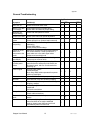
Troubleshooting
Please refer to the troubleshooting chart on page 13. If you still have a problem after trying those
solutions, please contact Chauvet Technical Support at (954) 929-1115 (press 4), or e-mail:
[email protected].
Returns Procedure
Returned merchandise must be sent prepaid and in the original packing, call tags will not be issued.
Package must be clearly labeled with a Return Authorization Number (RA #). Products returned
without an RA # will be refused. Call CHAUVET and request an RA # prior to shipping the fixture. Be
prepared to provide the model number, serial number and a brief description of the cause for the
return. Be sure to properly pack fixture, any shipping damage resulting from inadequate packaging is
the customer’s responsibility. CHAUVET reserves the right to use its own discretion to repair or
replace product(s). As a suggestion, proper UPS packing or double-boxing is always a safe method
to use.
Note:
If you are given an RA #, please include the following information on a piece of paper
inside the box:
1)
Your name
2)
Your address
3)
Your phone number
4)
The RA #
5)
A brief description of the symptoms
Claims
Damage incurred in shipping is the responsibility of the shipper; therefore the damage must be reported to the
carrier upon receipt of merchandise. It is the customer's responsibility to notify and submit claims with the
shipper in the event that a fixture is damaged due to shipping. Any other claim for items such as a missing
component/part, damage not related to shipping, and concealed damage, must be made within seven (7) days
of receiving merchandise.
Stepper User Manual
14
2006-12-12/09:53
Technical Specifications
WEIGHT & DIMENSIONS
Length.............................................................................................................................................. 15 in (381 mm)
Width................................................................................................................................................ 15 in (381 mm)
Height .............................................................................................................................................. 12 in (305 mm)
Weight.............................................................................................................................................11.5 lbs (5.2 kg)
POWER
Switch-selectable power ................................................................................................115V 60 Hz or 230V 50 Hz
AC input ......................................................................................................... 3-prong IEC 60320 C14 male socket
Power consumption ................................................................................................................ 592W peak @ 120V)
Inrush current................................................................................................................................ 1,276W @ 120V)
LAMP
CH64535................................................................................................................................................650W 120V
CH64540................................................................................................................................................650W 230V
THERMAL
Maximum ambient temperature ..........................................................................................................104° F (40°C)
FUSE
Main ......................................................................................................................20mm Glass 7A Fast Blow 250V
CONTROL & PROGRAMMING
Data input ................................................................................................................ locking 3-pin XLR male socket
Data output .......................................................................................................... locking 3-pin XLR female socket
Data pin configuration................................................................................ pin 1 shield (ground), pin 2 (-), pin 3 (+)
Protocols........................................................................................................................................ DMX-512 USITT
DMX Channels........................................................................................................................................................2
ORDERING INFORMATION
Stepper ....................................................................................................................................................STEPPER
Blackout Controller ..........................................................................................................................................CH-X
Stepper User Manual
15
2006-12-12/09:53