1
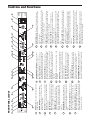
S Class Signal Processors
STEREO/MONO CROSSOVER
Safety Instructions/Consignes de sécurité/Sicherheitsvorkehrungen/Instrucciones de seguridad
WARNING: To reduce the risk of fire or electric shock, do not expose this unit to
rain or moisture. To reduce the hazard of electrical shock, do not remove cover or
back. No user serviceable parts inside. Please refer all servicing to qualified personnel.The lightning flash with an arrowhead symbol within an equilateral triangle,
is intended to alert the user to the presence of uninsulated "dangerous voltage"
within the products enclosure that may be of sufficient magnitude to constitute a
risk of electric shock to persons. The exclamation point within an equilateral triangle is intended to alert the user to the presence of important operating and maintenance (servicing) instructions in the literature accompanying the product.
Important Safety Instructions
1. Please read all instructions before operating the unit.
2. Keep these instructions for future reference.
3. Please heed all safety warnings.
4. Follow manufacturers instructions.
5. Do not use this unit near water or moisture.
6. Clean only with a damp cloth.
7. Do not block any of the ventilation openings. Install in accordance with the
manufacturers instructions.
8. Do not install near any heat sources such as radiators, heat registers, stoves,
or other apparatus (including amplifiers) that produce heat.
9. Do not defeat the safety purpose of the polarized or grounding-type plug. A
polarized plug has two blades with one wider than the other. A grounding type
plug has two blades and a third grounding prong. The wide blade or third
prong is provided for your safety. When the provided plug does not fit your
outlet, consult an electrician for replacement of the obsolete outlet.
10. Protect the power cord from being walked on and pinched particularly at
plugs, convenience receptacles and at the point at which they exit from the
unit.
11. Unplug this unit during lightning storms or when unused for long periods of
time.
12. Refer all servicing to qualified personnel. Servicing is required when the unit
has been damaged in any way, such as power supply cord or plug damage, or
if liquid has been spilled or objects have fallen into the unit, the unit has been
exposed to rain or moisture, does not operate normally, or has been dropped.
ATTENTION: Pour éviter tout risque d’électrocution ou d’incendie, ne pas
exposer cet appareil à la pluie ou à l’humidité. Pour éviter tout risque d’électrocution, ne pas ôter le couvercle ou le dos du boîtier. Cet appareil ne contient aucune
pièce remplaçable par l'utilisateur. Confiez toutes les réparations à un personnel qualifié. Le signe avec un éclair dans un triangle prévient l’utilisateur de la
présence d’une tension dangereuse et non isolée dans l’appareil. Cette tension
constitue un risque d’électrocution. Le signe avec un point d’exclamation dans
un triangle prévient l’utilisateur d’instructions importantes relatives à l’utilisation
et à la maintenance du produit.
Consignes de sécurité importantes
1. Veuillez lire toutes les instructions avant d’utiliser l’appareil.
2. Conserver ces instructions pour toute lecture ultérieure.
3. Lisez avec attention toutes les consignes de sécurité.
4. Suivez les instructions du fabricant.
5. Ne pas utiliser cet appareil près d’une source liquide ou dans un lieu
humide.
6. Nettoyez l’appareil uniquement avec un tissu humide.
7. Veillez à ne pas obstruer les fentes prévues pour la ventilation de l’appareil.
Installez l’appareil selon les instructions du fabricant.
8. Ne pas installer près d’une source de chaleur (radiateurs, etc.) ou de tout
équipement susceptible de générer de la chaleur (amplificateurs de puissance par exemple).
9. Ne pas retirer la terre du cordon secteur ou de la prise murale. Les fiches
canadiennes avec polarisation (avec une lame plus large) ne doivent pas
être modifiées. Si votre prise murale ne correspond pas au modèle fourni,
consultez votre électricien.
10. Protégez le cordon secteur contre tous les dommages possibles (pincement, tension, torsion,, etc.). Veillez à ce que le cordon secteur soit libre,
en particulier à sa sortie du boîtier.
11. Déconnectez l’appareil du secteur en présence d’orage ou lors de périodes
d’inutilisation prolongées.
12. Consultez un service de réparation qualifié pour tout dysfonctionnement
(dommage sur le cordon secteur, baisse de performances, exposition à la
pluie, projection liquide dans l’appareil, introduction d’un objet dans le boîtier, etc.).
ACHTUNG: Um die Gefahr eines Brandes oder Stromschlags zu verringern, sollten Sie dieses Gerät weder Regen noch Feuchtigkeit aussetzen.Um die Gefahr
eines Stromschlags zu verringern, sollten Sie weder Deckel noch Rückwand des
Geräts entfernen. Im Innern befinden sich keine Teile, die vom Anwender
gewartet werden können. Überlassen Sie die Wartung qualifiziertem
PRECAUCION: Para reducir el riesgo de incendios o descargas, no permita que
este aparato quede expuesto a la lluvia o la humedad. Para reducir el riesgo de
descarga eléctrica, nunca quite la tapa ni el chasis. Dentro del aparato no hay
piezas susceptibles de ser reparadas por el usuario. Dirija cualquier reparación al
servicio técnico oficial. El símbolo del relámpago dentro del triángulo equilátero
pretende advertir al usuario de la presencia de “voltajes peligrosos” no aislados
dentro de la carcasa del producto, que pueden ser de la magnitud suficiente como
para constituir un riesgo de descarga eléctrica a las personas. El símbolo de exclamación dentro del triángulo equilátero quiere advertirle de la existencia de importantes instrucciones de manejo y mantenimiento (reparaciones) en los documentos
que se adjuntan con este aparato.
Instrucciones importantes de seguridad
1.
Lea todo este manual de instrucciones antes de comenzar a usar la unidad.
2.
Conserve estas instrucciones para cualquier consulta en el futuro.
3.
Cumpla con todo lo indicado en las precauciones de seguridad.
4.
Observe y siga todas las instrucciones del fabricante.
5.
Nunca utilice este aparato cerca del agua o en lugares húmedos.
6.
Limpie este aparato solo con un trapo suave y ligeramente humedecido.
7.
No bloquee ninguna de las aberturas de ventilación. Instale este aparato de
acuerdo a las instrucciones del fabricante.
8.
No instale este aparato cerca de fuentes de calor como radiadores, calentadores, hornos u otros aparatos (incluyendo amplificadores) que produzcan
calor.
9.
No anule el sistema de seguridad del enchufe de tipo polarizado o con toma
de tierra. Un enchufe polarizado tiene dos bornes, uno más ancho que el
otro. Uno con toma de tierra tiene dos bornes normales y un tercero para la
conexión a tierra. El borne ancho o el tercero se incluyen como medida de
seguridad. Cuando el enchufe no encaje en su salida de corriente, llame a un
electricista para que le cambie su salida anticuada.
10. Evite que el cable de corriente quede en una posición en la que pueda ser
pisado o aplastado, especialmente en los enchufes, receptáculos y en el
punto en el que salen de la unidad.
11. Desconecte de la corriente este aparato durante las tormentas eléctricas o
cuando no lo vaya a usar durante un periodo de tiempo largo.
12. Dirija cualquier posible reparación solo al servicio técnico oficial. Deberá
hacer que su aparato sea reparado cuando esté dañado de alguna forma,
como si el cable de corriente o el enchufe están dañados, o si se han derramado líquidos o se ha introducido algún objeto dentro de la unidad, si esta ha
quedado expuesta a la lluvia o la humedad, si no funciona normalmente o si
ha caído al suelo.
Fachpersonal.Der Blitz mit Pfeilspitze im gleichseitigen Dreieck soll den Anwender
vor nichtisolierter “gefährlicher Spannung” im Geräteinnern warnen. Diese
Spannung kann so hoch sein, dass die Gefahr eines Stromschlags besteht. Das
Ausrufezeichen im gleichseitigen Dreieck soll den Anwender auf wichtige
Bedienungs- und Wartungsanleitungen aufmerksam machen, die im mitgelieferten
Informationsmaterial näher beschrieben werden.
Wichtige Sicherheitsvorkehrungen
1. Lesen Sie alle Anleitungen, bevor Sie das Gerät in Betrieb nehmen.
2. Bewahren Sie diese Anleitungen für den späteren Gebrauch gut auf.
3. Bitte treffen Sie alle beschriebenen Sicherheitsvorkehrungen.
4. Befolgen Sie die Anleitungen des Herstellers.
5. Benutzen Sie das Gerät nicht in der Nähe von Wasser oder Feuchtigkeit.
6. Verwenden Sie zur Reinigung des Geräts nur ein feuchtes Tuch.
7. Blockieren Sie keine Belüftungsöffnungen. Nehmen Sie den Einbau des
Geräts nur entsprechend den Anweisungen des Herstellers vor.
8. Bauen Sie das Gerät nicht in der Nähe von Wärmequellen wie Heizkörpern,
Wärmeklappen, Öfen oder anderen Geräten (inklusive Verstärkern) ein, die
Hitze erzeugen.
9. Setzen Sie die Sicherheitsfunktion des polarisierten oder geerdeten Steckers
nicht außer Kraft. Ein polarisierter Stecker hat zwei flache, unterschiedlich breite Pole. Ein geerdeter Stecker hat zwei flache Pole und einen dritten
Erdungsstift. Der breitere Pol oder der dritte Stift dient Ihrer Sicherheit. Wenn
der vorhandene Stecker nicht in Ihre Steckdose passt, lassen Sie die veraltete
Steckdose von einem Elektriker ersetzen.
10. Schützen Sie das Netzkabel dahingehend, dass niemand darüber laufen und
es nicht geknickt werden kann. Achten Sie hierbei besonders auf Netzstecker,
Mehrfachsteckdosen und den Kabelanschluss am Gerät.
11. Ziehen Sie den Netzstecker des Geräts bei Gewittern oder längeren
Betriebspausen aus der Steckdose.
12. Überlassen Sie die Wartung qualifiziertem Fachpersonal. Eine Wartung ist
notwendig, wenn das Gerät auf irgendeine Weise, beispielsweise am Kabel
oder Netzstecker beschädigt wurde, oder wenn Flüssigkeiten oder Objekte in
das Gerät gelangt sind, es Regen oder Feuchtigkeit ausgesetzt war, nicht
mehr wie gewohnt betrieben werden kann oder fallen gelassen wurde.
-
Table of Contents
Introduction
2
S•2-way Features
3
Controls and Functions
Front Panel Layout
Rear Panel Layout
4
5
Operating the S•2-Way
Setting Up the S•2-way
Setting up the S•2-way for Stereo 2-way Operation
S•2-way Controls
S 2•Way System Set-Ups
Mono 3-way Operation
SETTING UP THE S 2-way USING A REAL TIME ANALYZER
6
7-8
9
10
11 - 12
S•2-way Connections
13
Block Diagram
14
Specifications
15
Notes
16
s
Copyright 2003, Samson Technologies Corp.
Printed February, 2004
Samson Technologies Corp.
575 Underhill Blvd.
P.O. Box 9031
Syosset, NY 11791-9031
Phone: 1-800-3-SAMSON (1-800-372-6766)
Fax: 516-364-3888
www.samsontech.com
Introduction
Thank you for purchasing the Samson S 2-way electronic crossover. The Samson S 2-way is
a one rack-space, dual channel electronic signal processor capable of managing frequency
crossover for stereo 2-way and mono 3-way speaker systems. The S 2-way is an ideal
crossover solution for small and large PA systems, live sound venues, commercial installations, recording studio monitors and DJ set-ups. The S 2-way is easy to configure for stereo or
mono operation by using the front panel mode switch. In addition to its flexibility in configuring
to different sound systems, the S 2-way has advanced features such as Delay control for time
aligning speakers plus individual Phase and Mute switches for each frequency band. S 2way’s convenient meters and back-lit switches provide instant status of levels and important
speaker management settings. Perhaps the best attribute of the S 2-way is its clean and transparent signal path, thanks to the advanced electronic design and the use of high quality components. The S 2-way is a complete electronic crossover solution, which will give you precise
control and superior sound from your loudspeaker system.
In these pages, you’ll find a detailed description of the features of the S 2-way electronic
crossover, as well as a guided tour through its front and rear panels, step-by-step instructions
for its setup and use, and full specifications. You’ll also find a warranty card enclosed—please
don’t forget to fill it out and mail it in so that you can receive online technical support and so
we can send you updated information about these and other Samson products in the future.
With proper care and adequate air circulation, your S 2-way will operate trouble free for many
years. We recommend you record your serial number in the space provided below for future
reference.
Serial number:
Date of purchase:
Should your unit ever require servicing, a Return Authorization number (RA) must be obtained
before shipping your unit to Samson. Without this number, the unit will not be accepted.
Please call Samson at 1-800-3SAMSON (1-800-372-6766) for a Return Authorization number
prior to shipping your unit. Please retain the original packing materials and if possible, return
the unit in the original carton and packing materials.
2
S 2-way Features
The Samson S 2-way electronic crossover utilizes the latest technology in crossover filters and speaker
management design. Here are some of its main features:
•
Full featured, Stereo 2-way, Mono 3-way electronic crossover.
•
Precision Linkwitz-Riley, 24 dB/Octave filters.
•
Each channel incorporates a High Pass Filter, Butterworth 25 Hz, 12 dB/Octave, to help you
reduce stage rumble and the engery loss from sub-sonic frequencies.
•
For time aligning speaker stacks, each Low Frequency output can be delayed for phase correction by using the adjustable Delay control located on the front panel.
•
The X10 Range switch allows to adjust frequency range of the filter, allowing you to change
from mid-band to high-band.
•
The four segment LED Input Gain meter allows you to monitor the signal level and make easy
gain adjustment.
•
In the Master Control Section, there is a Mute switch for each of the individual outputs, allowing
you to listen to the different sections of the speaker systems seperately.
•
Phase Switches are included in the Master Control Section to invert the phase of the individual
outputs.
•
Servo balanced inputs and outputs on XLR connectors.
•
Pristine audio quality thanks to the advanced circuit design, utilizing low noise operational
amplifiers and high quality VCAs.
•
High quality metal shaft pots and backlit switches.
•
The stylish, electric blue, alluminum front-panel is as easy to read as it is to look at.
•
Three-year extended warranty.
3
DELAY (CH 1) – This control is used to adjust the
delay line from 0 to 2ms, for time aligning the low
frequency output.
LOW GAIN (CH 1) - Adjusts the output level of the
LOW frequency band for the left in stereo 2-way
mode, or for the LOW band in mono 3-way mode.
FREQUENCY (CH 1) - This control sets the
crossover point dividing the frequency bands
from low-to-high in stereo 2-way mode, or from
low-to-mid when you are operating in mono 3way mode.
HIGH GAIN (CH 1) - Adjusts the output level of
the HIGH frequency band for Channel 1 in stereo
2-way mode, or for the MID band in mono 3-way
mode.
PHASE Switch (MID / HIGH CH1) - Used to invert
the phase on the left HIGH output in stereo 2-way
mode, or the MID output in mono 3-way mode.
MUTE Switch (MID / HIGH CH 1) - This switch is
used to defeat the output for the HIGH frequency
output when operating in stereo 2-way mode, or
to defeat the MID frequency output when operating in mono 3-way mode.
4
5
6
7
8
20
6
3
5
INPUT METER (CH 1) – Four-segment LED VU
meter displays the amount of level present at the
Channel 1, or left, input.
4
2
3
INPUT GAIN - Used to adjust the input gain from
–12dB to +12dB.
19
STEREO/MONO
CROSSOVER
2
1
1
FRONT PANEL LAYOUT
9
MASTER CONTROLS
23
10
11
24
4
INPUT GAIN - Used to adjust the input level from –12dB
to +12dB.
DELAY (CH 2) – This control is used to adjust the delay
line, from 0 to 2ms, for time aligning the channel 2 low
frequency output. This control has no effect when operating in stereo 3-way mode.
LOW GAIN CONTROL (CH 2) - Adjusts the output level
of the LOW frequency band for right in stereo 2-way
mode. This control has no effect when operating in
stereo 3-way mode.
FREQUENCY CONTROL (CH 2) - This control sets the
crossover point dividing the frequency bands from lowto-high in stereo 2-way mode, or from mid-to-high
when you are operating in mono 3-way mode.
HIGH GAIN CONTROL (CH 2) - Adjusts the output level
of the HIGH frequency band for Channel 2 in stereo 2way mode, or for the HIGH band in mono 3-way mode.
14
15
16
17
INPUT METER (CH 2) – Four-segment LED VU meter displays the amount of level present at the Channel 2, or
lright input.
12
13
MUTE Switch (HIGH CH 2) - This switch is used to
defeat the output for the HIGH frequency output when
operating in stereo 2-way mode, or to defeat the HIGH
frequency output when operating in mono 3-way mode
PHASE Switch (HIGH CH2) - Used to invert the phase
on the right HIGH output in stereo 2-way mode, or the
HIGH output when operating in mono 3-way mode.
OPERATING MODE SELECTOR - Selects one of the 2
operating modes, 2-way stereo or 3-way mono.
22
8
11
10
9
21
7
MUTE Switch (LOW CH1) - This switch is used to defeat the LOW
frequency output when operating in stereo 2-way mode, or to
defeat the LOW frequency output when operating in mono 3-way
mode.
PHASE Switch (LOW CH2) - Used to invert the phase on the right
LOW output in stereo 2-way mode. This control has no effect when
operating in stereo 3-way mode.
MUTE Switch (LOW CH 2) - This switch is used to defeat the output for the right LOW frequency output when operating in stereo
2-way mode. This control has no effect when operating in stereo 3way mode.
HPF Switch (CH2) - Engages the High Pass Filter, or low cut, rolling
off the low frequencies at 25Hz, by12 dB per octave, helping to
reduce unwanted low frequency rumble. This control has no effect
when operating in stereo 3-way mode.
RANGE Switch (CH 2)– This switch is used to change the frequency range of the crossover filter from 35 Hz to 800 Hz, or from 350
Hz to 8 kHz when the switch is engaged.
22
23
24
25
26
PHASE Switch (LOW CH1) - Used to invert the phase on the
leftLOW output in stereo 2-way mode, or the LOW output when
operating in mono 3-way mode.
21
18
RANGE Switch (CH 1)– This switch is used to change the frequency range of the crossover filter from 35 Hz to 800 Hz, or from 350
Hz to 8 kHz when the switch is engaged.
17
20
26
16
HPF Switch (CH1) - Engages the High Pass Filter, or low cut, rolling
off the low frequencies at 25Hz, by12 dB per octave, helping to
reduce unwanted low frequency rumble.
15
19
14
MAIN POWER Switch - When this switch is engaged, the green
LED will illuminate indicating that the S 2-way is powered up and
ready for operation.
25
13
18
12
Controls and Functions
5
D
C
B
A
CHANNEL 2 INPUT - XLR balanced line INput.
output.
CHANNEL 2 LOW OUTPUT - XLR balanced line
PUT - XLR balanced line output.
CHANNEL 2 HIGH OUTPUT?MONO HIGH OUT-
tor with external fuse.
AC INLET - IEC standard ac power cable connec-
REAR PANEL LAYOUT
G
F
E
anced line
input.
CHANNEL 1 INPUT/MONO INPUT - XLR bal-
PUT - XLR balanced line output.
CHANNEL 1 LOW OUTPUT/MONO LOW OUT-
PUT - XLR balanced line output.
CHANNEL 1 HIGH OUTPUT/MONO MID OUT-
Controls and Functions
Operating the S 2-way
SETTING UP THE S 2-way
Whether you are an experienced audio engineer or just starting out, the following sections of this manual will help
you get going with your S 2-way. Now that you have unpacked the unit and have become a bit familiar with the
front panel controls, you can follow the next sections of this manual to begin to set-up and operate your new
crossover. Further on in this manual, you will find detailed wiring diagrams of various speaker system set-ups.
For detailed diagrams of connector and cable wiring, see page 13 in this manual.
MODE SWITCH
The S 2-way can be configured to operate in two modes including Stereo 2-way and Mono 3-way. The Mode Switch, located in
the center section of the unit, is used to select one of the two
operating modes. Notice that the outlined box around the ledged
“3W” highlights the 3-way Mono position. If you operate the unit
in 3-way mono mode, you will find that some of the functions
change the band that the control. The 3-way parameters for
these switches and control knobs are indicated by the outlined
box.
MONO 3-WAY INDICATORS
Because the S 2-way can be configured to operate in either stereo 2-way or mono 3-way, the channel 1
crossover controls may be adjusted for the frequency division between low and high, or low and mid depending
on the mode. On some crossovers, it is very difficult to get a quick visualization as to what controls are controlling
what function. The S 2-way solves this problem by highlighting the function with the outlined box around the legend over Frequency and Gain controls. You will see the same indication for the Phase and Mute switches in the
master section. These provide quick identification of the frequency band that is under control. In the diagram
below, you can see what functions are under control when operating in mono 3-way mode.
Channel One
1 FREQ
2
3
4
5
L/M
MID
MID
MONO 3W
Channel Two
6 M/H
7 FREQ
Times 10 Frequencies
(when RANGE switch is
engaged).
Crossover Low to Mid
Mid Frequency GAIN control
PHASE switch
Operating mode switch
Crossover Mid to High
Times 10 Frequencies (when
RANGE switch is engaged).
6
6
7
Operating the S 2-way
SETTING UP THE S 2-way FOR STEREO 2-way OPERATION
The following operating example is for a Stereo 2-way system using a 15" low frequency driver and a 1" compression driver on both the left and right sides.
CAUTION: Before you apply power to your speaker system amplifiers, be certain to set the frequency controls to
the manufacturers recommended crossover points for the drivers or enclosures you are using.
NOTE: LAST ON / FIRST OFF
When running a loudspeaker system with one or multiple power amplifiers, it is highly recommended that you follow the LAST ON / FIRST OFF rule. When powering up your sound system, turn your power amplifier on last.
When you power down your system, turn your power amplifiers off first. This will prevent any switching spikes
you may get from other gear in your system, and help prevent unnecessary pops that can sometimes cause
speaker damage.
•
Connect both sets of inputs and outputs to the designated connectors on the rear panel. For a detailed
cable-wiring diagram see page 13.
*
Set the controls to the following positions:
INPUT GAIN
DELAY
LOW GAIN
LOW/MID FREQUENCY
RANGE SWITCH
HIGH GAIN
MODE SWITCH
HIGH PHASE
LOW PHASE
HIGH MUTE
LOW MUTE
-12
0
-6
2.6 kHz
IN
-6
ST 2W
OUT
OUT
IN
IN
•
Set the controls for the S 2-way’s Channel 2 to the same positions.
•
Set the Power Switch to the ON position.
•
Connect the mixer’s left output to the S 2-way’s CH1 (Left) input and the mixer’s right output to the S 2way’s CH2 (Right) input. Next, connect the S 2-way’s CH1 (Left) Low Output to the left input of the
power amp operating the low frequency drivers, and then, connect the CH1 High Output to the left input
of the power amp operating the High frequency drivers. Now, make the same connections for the S 2way’s CH2(Right) and amplifiers right side.
7
Operating the S 2-way
Once you have your system wired-up, follow the steps below:
•
Set the mode switch to the ST 2 W position. Notice the silkscreen
BAND INDICATORs showing the frequencies that are now under
control by the associated GAIN or FREQUENCY knobs.
•
Use the FREQUENCY control on Channel 1 and 2 to set the desired
crossover point.
•
Lower your power amplifier outputs to all the way off. Turn on all
your power amplifiers. Run an audio signal (like some music from a
CD) through your mixer and raise the output faders until you see the
Input Meter LED’s begin to light.
•
Slowly raise the S 2-way’s Input Gains until the Input Meters read
0dB.
•
Now raise your power amps to their normal operating level.
•
Slowly raise the S 2-way’s Ch1 (Left) Low Gain to 0 and then raise
CH2 (Right) Low Gain to 0.
•
Slowly raise the S 2-way’s Ch1 (Left) High Gain to 0 and then raise
CH2 (Right) HIGH Gain 0.
•
Now use an RTA (Real Time Analyzer), or an even more sophisticated piece of test gear, your ears, to adjust the balance between
the low, (mid) and high end. You can continue to raise the Gain
controls as you fine-tune the system. Watch the Peak Meters on
your power amplifiers to ensure that you’re running a clean signal.
8
Operating the S 2-way
S 2-way Controls
The Samson S 2-way features a variety of control functions that offer the sound engineer advanced control over a
speaker system. The next section is a description of the control functions and how they are used to improve the
overall sound of a sound reinforcement system.
HIGH PASS FILTER
The S 2-way incorporates a HPF (High Pass Filter) which when engaged,
activates a low frequency roll off at 25 Hz. By using the HPF, you eliminate the sub-sonic frequencies sent to the low frequency power amplifier.
Since the amplifier will try to reproduce these frequencies when the HPF is
off, in most cases the result is simply wasted energy. By using the S 2way HPF you send just the frequencies you want to reproduce to your low
frequency amplifiers and speakers.
DELAY
The S 2-way features a delay that can be set for up to two milliseconds of
delay time for time aligning speaker stacks.
PHASE SWITCHES
The S 2-way incorporates individual PHASE reversal switches
on each frequency band. When engaged, the LED illuminates
indicating that the selected output is now 180 degrees out of
phase.
MUTE SWITCHES
The S 2-way features Mute switches on each frequency band.
When engaged, the LED illuminates and that channel output
is turned off. The MUTE switches are convenient for trouble
shooting or for simply listening to each speaker section separately.
9
S 2-way System Set-Ups
MONO THREE WAY OPERATION
If you’re operating your PA system Mono 3-way, wire your system as shown in the system diagram below.
Once you have your system wired-up, follow the steps below:
•
Locate the MODE switch in the master section and set it to the MONO 3 W position.
•
Notice the outlined boxes showing the frequencies that are now under control by the associated GAIN or
FREQUENCY knobs.
•
Now, use the first crossover FREQ on Channel 1 to set the desired
frequency dividing the low and mid frequencies.
•
Next, set the frequency point dividing the mid and high by using
Channel 2’s crossover FREQ control.
•
Now, adjust the first gain control on Channel 1 to set the level of the
LOW frequency output.
•
Next, adjust the second gain control on Channel 1 to set the level of
the MID frequency output.
•
Next, adjust the second gain control on Channel 2 to set the level of
the HIGH frequency output.
•
You can use an RTA (Real Time Analyzer), or an even more sophisticated piece of test gear, your ears,
to adjust the balance between the low, (mid) and high end. You can continue to raise the Gain controls
as you fine-tune the system. Watch the Peak Meters on your power amplifiers to ensure that you’re running a clean signal.
10
SETTING UP THE S 2-way USING A REAL TIME ANALYZER
SETTING UP THE S•2-way USING A REAL TIME ANALYZER
A REAL TIME ANALYZER (RTA) is an especially useful tool for setting up your crossover, as it will enable you
to set parameters like DELAY and LEVEL more accurately. Some Audio Engineers can use their ears to tune a
loudspeaker system. Some will even use the crossover to create the over-all system curve by using the
crossover like an equalizer. For the rest of us, an accurately set crossover with a flat response is the best way
to start and using a RTA, like the Samson D1500, is the best way to get there.
Using the RTA to Set DELAY Time.
In the real world, no single or multiple speaker system is perfect. If there were such a perfect system, it would
more than likely be comprised of a single transducer that alone could faithfully reproduce the entire frequency
spectrum. Because no such system exists, we have to deal with the problems associated with multiple transducers. The first problem that you will encounter, whether you know it or not, is time travel. That’s when the S
2-way’s delay circuit becomes especially useful.
Ideally, the sound reproduced by each driver in the loudspeaker system would be traveling through the air ultimately reaching the listeners at the same time. To accomplish this in a system using multiple drivers or enclosures, the voice coils of all the drivers would have to be lined up on the same vertical axis. This is very difficult
to achieve in many cases because of the physical size of the different components, and the position of the drivers in their enclosures. It is not uncommon to have a physical distance of 2” to 24" or more between the low
and high frequency drivers. For example, front loaded low frequency drivers and compression drivers mounted
on a large horn. With no correction, the low frequency signal can be traveling through the air 2" to 24" in front of
the high frequencies and thereby reaching the listeners at different times. Although the delay time between the
low and high frequency signal may be relatively small, the negative effects can be substantial. The problem is
that both drivers are reproducing frequencies at and around the crossover point, which arrive at the listeners at
different times. Typically, the resulting problem is comb filtering or cancellations at the crossover frequencies.
Using delay greatly helps to improve phasing problems (especially with low frequency drivers) and will help you
achieve a tighter, punchy low end response.
The S 2-way features a DELAY control allowing you to dial up to 2 milliseconds of delay. By using an RTA
and the S 2-way’s DELAY, you can time align the drivers in your system and minimize the possibilities of comb
filtering. Now follow these steps, separately, for both the left and rights sides of your loudspeaker:
•
Set the crossover to the desired frequencies and press all the Mute switches to the ON position, turning
all of the S 2-ways outputs off. Position your measurement microphone approximately 15 feet from
your loudspeaker array, halfway between the low and high frequency drivers. Now turn all the GAIN
controls to the fully counter clockwise position.
•
Play a sine wave tuned to the crossover frequency, or connect a pink noise generator to your loudspeaker system either from your mixer or in the S 2-way’s input. Now turn off the Low Frequency Mute
switch and adjust the S 2-way’s INPUT GAIN to "0”. Adjust the LOW GAIN control so that the signal is
playing at a loud, but not too painful level. Make sure you only hear sound from the low frequency driver.
•
Adjust the level control of the RTA until it reads OdB at the crossover frequency. Now press the LOW
MUTE switch turning off the low frequency output.
11
SETTING UP THE S 2-way USING A REAL TIME ANALYZER
•
Turn off the High Frequency MUTE switch and turn up the High Frequency Level control until the RTA
reads 0dB at the crossover frequency.
•
Now, press the LOW MUTE switch again turning on the low frequency output. Notice the reading on the
RTA at the crossover frequency. If the reading is 0dB, there is no need to adjust the delay time and you
can assume that the speakers are in phase. If the RTA reads less than +3dB you’ll need to delay the low
frequency.
•
While watching the RTA display, slowly turn the DELAY control counter-clockwise until the display reads
as close to +0dB as possible.
Setting the GAIN Controls Using a RTA
It is critical to set the GAIN output controls so that all the frequency bands combine to create an over-all flat system response. Using an RTA to set the GAIN control will make it much easier for you to accomplish a flat system
response. Follow the steps below, separately for each side of your system, to set the GAIN controls using an
RTA.
•
With the crossover set to the desired frequencies, press all the Mute switches to the ON position, turning
all of the S 2-way’s outputs off. Be sure that all of the PHASE switches are out (LED’s off). Position your
measurement microphone approximately 15 feet from your loudspeaker array at a level ranging from
your chest to your ear. Now turn all the GAIN controls to the fully counter clockwise position.
•
Play a sine wave tuned to the crossover frequency, or connect the signal from a pink noise generator to
your loudspeaker system, either from your mixer or directly in the S 2-way’s input. Now turn off the Low
Frequency Mute switch and adjust the S 2-way’s INPUT GAIN to "0’.
•
Adjust the LOW GAIN control until the RTA has an average reading of -3dB at and below the frequency
of the LOW crossover point.
•
Engage the LOW Mute.
•
Next, play a sine wave tuned to the crossover frequency, or connect the signal from a pink noise generator to your loudspeaker system, either from your mixer or directly in the S 2-way’s input. Now turn off the
HIGH Frequency Mute switch.
•
Adjust the HIGH GAIN control until the RTA has an average reading of -3dB at and above the frequency
of the HIGH crossover point.
•
Engage the HIGH mute and turn off the mute in the LOW frequency output. Check to see if the RTA is
still showing -3dB at the crossover point. Remember the High frequency output is also set for -3dB out
put, and since both the high and low frequency outputs are set to a level of -3dB at the crossover point,
the summed signal level will be 0dB.
Note: If you have trouble making the measurements as described above, be sure to check the position of
the PHASE switches, and also, check your balanced wiring for proper phase. For a detailed cable-wiring
diagram see page 13.
At this point all of the frequency bands will be at the same level and your system will have a flat response. After
setting the levels you can use a graphic equalizer, like the Samson S curve 231 or D 2500, if you want set a particular response curve to tune the speaker system for a specific sound.
12
Connections
Unbalanced 1/4” Connector
Balanced TRS 1/4” Connector
XLR Balanced Wiring Guide
13
Block Diagram
14
Specifications
Inputs
Female Balanced XLR
Impedance Balanced
Max. Input level
>15k Ohms
+26dBu balanced
Outputs
Male Balanced XLR
Impedance Balanced
Max. Output Level
100 Ohms
+26 dBu
Global Specifications
Frequency Response
<10 Hz to >90 kHz, +0/-3 dB
Signal to Noise
(Ref +4 dBu), 22 Hz to 22 kHz, un-weighted 90dB high out, mid 90dB, low 94dB, all outs >100dB muted
CMRR
Min.40dB, >55 dB @ 1 kHz
Crossover
Crossover Type
Crossover 1 Channel 1
Linkwitz-Riley, 24 dB/Octave
35 to 800Hz
350 to 8kHz / with 10X multiplier
Crossover 1 Channel 2
35 to 800Hz
350 to 8kHz / with 10X multiplier
Function Switches
Front Panel
High Pass Filter
Mute
Phase
-3dB @ 25Hz 2 pole, 12dB/Octave
For individual outputs
Inverts the phase of the individual output
Power Supply
Mains Voltages USA/Canada
Mains Voltages Europe
Power Consumption
Power Inlet
105-125 VAC ~, 60 Hz
215 – 254 VAC~,50Hz
14 Watts
Standard IEC receptacle / with Fuse
Physical
Dimensions
Net Weight
Shipping Weight
1 3/4" (44,5 mm) * 19" (482,6 mm) * 8 1/2" (217 mm)
6.6lbs., (3 kg)
9.4lbs., (4,3 kg)
15
Notes
16
Samson Technologies Corp.
575 Underhill Blvd.
P.O. Box 9031
Syosset, NY 11791-9031
Phone: 1-800-3-SAMSON (1-800-372-6766)
Fax: 516-364-3888
www.samsontech.com