1
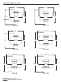
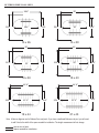
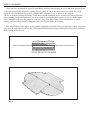
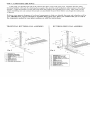
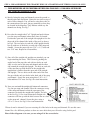
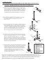
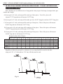
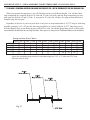
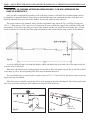
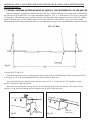
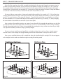
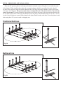
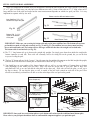
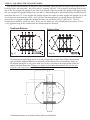
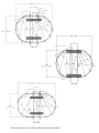
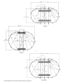
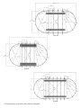
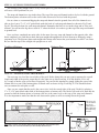
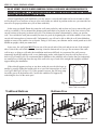
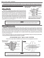
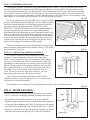
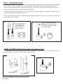
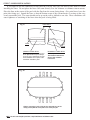
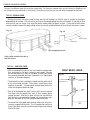
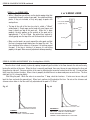
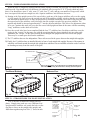
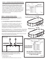
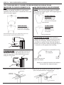
P /N 95-0444 02-06
Above Ground Pool Assembly & Installation
OVAL POOL INSTRUCTIONS
Buttress Free and Traditional Buttress
WA R N I N G :
THIS POOL IS NOT DESIGNED FOR DIVING OR JUMPING.
DANGEROUS INJURY CAN RESULT-SHALLOW WATER!!!
Follow All Safety and Maintenance Instructions
Your pool is designed for years of pleasurable, safe family fun. But, when
used incorrectly, a swimming pool can be dangerous. To insure your pool is
used safely you must observe the following safety precautions:
Do not dive!-Do not jump!- No rough play!- No running or pushing!
Do not walk on the top rail. It can be slippery and is not a walkway.
Be sure to install all safety labels provided with your pool according to the
instructions.
Keep a safety rope 1/4” by 50’ with a flotation buoy with an outside diameter of
15”. Have accessible in a prominent area by your pool.
Post near all entrances to pool area; a list of telephone numbers of the:
• Nearest available police
• Nearest ambulance service
• Nearest available fire department
• Nearest available hospital
• Nearest available rescue unit
• Nearest available physician
• 911 emergency number if available
Provide fencing or enclosure which is independent of the house as a closure
around the entire pool area. The fencing must be made of durable material, a
minimum of 4’ in height from ground level and with closures with self-latching
locks, to make pool inaccessible to toddlers and uninvited guests. Make sure
gate is always closed. Be sure to follow local building code requirements for load
capacity and fencing if using an aftermarket or homebuilt deck. You must make
sure all fence and barriers are in working order so that pool is always protected.
Check with your local town for any special laws in your locale.
Never drink alcoholic beverages or use any intoxicants which could hinder your
judgment and reflexes.
Never use pool alone. All children must be supervised continuously.
Do not use pool if bottom is not clearly visible: At night, sufficient lighting must
be available. It is the pool owners sole responsibility to provide adequate
lighting for pool bottom, safety signs and walkways, which exceeds minimum
standards of the IES of North America.
Do not climb, stand or sit on any pool structure or the filter system. Components
such as the filtration system, pumps and heater must be positioned so as to
prevent their being used as a means of access to the pool by young children.
Be sure that all toys, chairs and tables or similar objects that a young child could
climb on be at least four feet (4’) from pool.
Do not use pool during electrical or rain storms.
See available National Spa and Pool Institute (NSPI), publications for more tips on pool safety.
IMPORTANT NOTICE!
READ BEFORE INSTALLATION
WA R N I N G :
ENCLOSED IN FRAME CARTON IS SAFETY
ENVELOPE. THE SAFETY STICKERS MUST
DO NOT AFFIX
BE INSTALLED AS PER FOLLOWING
ANY OTHER PRODUCTS
INSTALL WARNING LABELS WILL VOID
MADE BY OTHERS
TO YOUR POOL
SUCH AS,
BUT NOT LIMITED TO,
DECKS AND SLIDES!
INSTRUCTIONS. FAILURE TO PROPERLY
WARRANTY. FAILURE TO MOUNT THESE
SAFETY LABELS MAY SUBJECT YOU TO
SUBSTANTIAL LIABILITY IN CASE OF INJURY.
THESE WARNINGS ARE NOT TO
BE REMOVED UNDER ANY CIRCUMSTANCES! IF THEY BECOME
DISCOLORED OR FALL OFF,
PLEASE REQUEST REPLACEMENTS WHICH WILL BE SENT AT
NO CHARGE.
SIGN MUST BE PLACED
ON WALL NEXT TO ENTRY
TO POOL
SIGN TO BE PLACED ON
LINER ABOVE WATER LINE
OPPOSITE ENTRY TO POOL
BUTTRESS-FREE POOL SIZES
19'
17'6"
15' 4"
15' 6"
10' 2"
17'
22' 4.5"
20'
17'
18'
12'
17'
20' 4.5"
12 x 18
12 x 20
25'10.5"
28'6"
23'10.5"
12 x 24
Actual size of pool.
Space needed for installation.
12'
12 x 17
10 x 16
17'
17'
12'
20'4"
26'6"
15 x 24
12'
15'2
BUTTRESS-FREE POOL SIZES
32'
28'6"
20'4"
23'4"
26'6"
15'2
20'4"
15 x 26
15 x 30
35'
42'
33'
18'2"
23'4"
18 x 44
18'2"
23'4"
42' 6"
21 x 43
Note: All above diagrams are for Buttress-Free oval pools. If you have a traditional Buttress oval pool, you will need
to add 3 feet to the width of the space needed for installation. The length measurement will not change.
Actual size of pool.
Space needed for installation.
18'2"
44' 6"
45' 6"
43' 6"
40'
15'2"
18 x 40
18 x 33
23'4"
30'
18'2"
INTRODUCTION:
Congratulations on becoming the owner of a new above ground swimming pool. This is the instruction packet
for installing your swimming pool. The following are some helpful hints that you should take into consideration
before installing your pool.
1) Read through the entire instruction booklet before you begin. This will enable you to find out exactly what is
involved with installing your swimming pool before you begin. While you are going through the instructions,
please be aware that all of the diagrams are representative of a 15' x 30'/18' x 33' pool. If you have a different
size pool you will find that your pool has a different number of uprights than the ones in the diagrams.
2) DO NOT ATTEMPT INSTALLATION IN WINDY OR GUSTY WEATHER. This will not only make
installation more difficult, it may result in damage to your pool before it is completely installed.
3) Although we have broken down the installation into many simple steps, you will probably find that steps one
and two will be the most labor intensive and time consuming steps. Once you have completed those two steps
you should find that the rest of the installation moves along much more quickly.
4) Please be sure to review all safety material and local codes before beginning your installation. There is a yellow
safety envelope packed with your pool. This envelope contains safety material and warning stickers to be
placed on your pool. If you are missing any of these items please contact your dealer or the factory to obtain it.
The warranty is void if all safety precautions are not followed.
5) In the event that you need to make a warranty claim, it is important to know the size and model of your
swimming pool in order to expedite the handling of your claim. Please fill in the information below and keep
for your records. All of this information can be found on the labels attached to the cartons your pool is packed in.
NAME OF POOL:
SIZE OF POOL:
DATE OF PURCHASE:
NAME OF POOL WALL:
NAME OF LINER:
6) Make sure you have the necessary tools and materials before beginning your installation.
Below is a list of the tools and materials needed.
-Shovel
-Carpenters level and/or transit (Optional)
-Tape measure
-Patio Blocks (2" x 8" x 16")
-Phillips head screwdriver
-Box cutter (Razor blade)
-Duct tape
-Tamp
-Sand
-5/16" wrench
-Filter
-1/4" wrench
-Skimmer/Return fitting
POOL LOCATION:
Do not locate pool over underground lines,
septic tanks, under electrical lines, near hazardous
structures, or out of local code restrictions. It is
essential that the area selected for your pool has
a level and firm base. Do not assemble your pool
on asphalt, tar or oil base surfaces. Avoid areas
with sharp objects, or ground treated with weed
killer or other chemicals. Also avoid areas where
nut grass, Bermuda grass or bamboo grass grows,
as they can grow through your liner. Grass must
be removed. Do not place components such as
filters, pumps, and heaters in a way that they can
be used as a means of access to pool by young
children. Be sure to follow all local building codes
and obtain all building permits required for your area.
*BE SURE TO AVOID:
-All electrical wires
-All gas lines
-Septic tanks
-Cesspools
-Dry wells
-Tree roots/stumps
-buried debris(trees,
building material, etc.)
-sudden slopes within 6’
of pool area
e
l
p
am
S
Fig. 1
STEP 1 – PREPARING THE SITE:
Refer to the "True Size" diagram on the second page to see the dimensions of your swimming pool. Once you
have these measurements and have chosen a site to install your pool, mark or outline the ground where the pool
will be going using spray paint or some other marking agent. Please keep in mind that you will need some extra
room to work. Be sure to account for the space that the side supports extend out on each side of an oval pool.
The strap end channel extends out 37" from the wall of the pool on each of the two straight sides of a Traditional
Buttress oval. If you have a Buttress-Free oval pool system, the strap end channel extends only 19" out from the
wall on each side. Refer to the "Actual Size" chart for further clarification.
For example, a 15x30 oval should have the following space in order to install the pool.
Traditional Buttress Oval:
Buttress-Free Oval:
32'
23'4"
Fig. 2
30'
15 x 30
32'
15'2"
20'4"
Fig. 2A
30'
15'2"
15 x 30
*Once you have the appropriate area marked out, remove any sod that is in the area. Also be sure to avoid all electrical wires,
gas lines, septic tanks, cesspools, dry wells, tree roots, stumps, buried debris, and sudden slopes within 6’ of the pool area.
STEP 2 – LEVELING:
Once you have designated the space for installation, and have cleared away the sod in that area, you can begin
to level the ground. The ideal tool for doing this is a transit. If you do not have access to a transit, use a long
board (be sure that the board is perfectly straight) and a carpenters level, as shown in the diagram.
The key to properly leveling the surface for an above ground swimming pool is to start at the lowest point and
dig everything else down to that level. You do not want to build up the lower areas to be level with the higher
areas. Doing this will cause the ground to settle once the pool is full of water. If the ground settles it could
destroy your pool, which could be dangerous and is not covered under the warranty.
Remove soil and grass to this level.
}
}
You will probably not be able to get the ground completely level until you lay out the frame, but the closer you
get it now the easier the job will be later. We recommend that you do not proceed until the entire site is within an
inch of being perfectly level.
Remove grass only from low areas.
* DO NOT ADD DIRT TO LOW AREAS.
Fig. 3
Fig. 4
STEP 4 - PRE-ASSEMBLING THE STRAIGHT SIDES OF A TRADITIONAL BUTTRESS OVAL POOL ONLY:
*** THESE INSTRUCTIONS ARE FOR TRADITIONAL BUTTRESS OVAL POOLS ONLY!!! IF YOU HAVE A BUTTRESS-FREE
OVAL PLEASE USE ALTERNATE STEP FOUR.
A) Start by laying the strap end channels out on the ground so
that the open ends face down. Notice the two slots on top of
each of these channels. You will not be using these slots in
the construction of the pool, but pay attention to where they
are located in the diagrams. They indicate which way the
channels are facing. See Fig.7
Fig. 7
B) Now take the straight side 4"x4" Upright and push it down
over the strap end channel where those slots are located.
Position the open end of the straight side upright to face the
short end of the channel (the inside of the pool) as shown
in Fig.8. The two holes on each side of the upright should
line up with two of the holes on each side of the strap end
channel. Secure the parts with two 5/16" x 4 ½" bolts and
two 5/16" nuts. Repeat for all assemblies.
Fig. 8
C) Once all of the straight side uprights are attached, you can
begin attaching the struts. This is done by pushing the
angled end of the strut (the end with two holes on each
side) over the end of the strap end channel and the other
side around the straight side upright. The hole on each side
of the strut lines up with the hole in the straight side
upright that is farthest from the open end of the straight
side upright. The two holes on the other end of the strut
line up with the only two holes in the back end of the strap
end channel. Secure the struts using three 5/16" x 4 ½"
bolts and three 5/16" nuts. See Fig.9 for visual instructions.
D) Now you can install the straight side bottom rail connectors.
Use one per strap end channel. Place the connector on top
of the strap end channel so that the open part of the
connector sits inside the straight side upright. The hole
in the See Fig. 10 for visual instructions straight side
connector will line up with the hole between the two slots
on the strap end channel. Secure the piece using a
Fig. 10
#12 x ¾" screw. See Fig.10 for visual instructions.
Fig. 9
PA RT I D E N T I F I E R
*Please do not be alarmed if you are not using all of the holes in the strap end channels. We use this same
channel for a few different products so there are some holes that you will not be using for this pool.
Please follow diagrams to be sure you are using all of the correct holes.
ALTERNATE STEP 4 PRE-ASSEMBLING THE STRAIGHT SIDES OF A BUTTRESS-FREE OVAL POOL ONLY:
*** IF YOU HAVE A TRADITIONAL BUTTRESS OVAL PLEASE REFER TO THE PREVIOUS STEP 4!
A) Start by laying out the under box channels so that the open
sides of each under box channel is facing up. Then slide the
strap end channel over the top of the under box channels so
that they form a tube. Be sure that the holes in both channels
are aligned, but do not bolt them together yet. See Fig. 11
Fig. 11
B) Now slide the straight side 4"x4" uprights over the strap
end channels making sure that the holes line up as
shown in Fig.12.
Fig. 12
C) Once the straight side 4"x4" uprights are attached, apply the
left and right side gussets on each. The pieces are marked
"L" and "R". The gussets are applied under the channels and
around the straight side upright. Once you have them in
place screw the left and right gussets to each other using
three #10 screws. See Fig.13 for visual instructions.
D) All holes should be lined up at this point. Bolt the components
together as shown in the diagram. Use 5/16" x 5" long bolts
and 5/16" nuts for the channels, and 5/16" x 4 ½" long
stainless steel bolts for connecting the gussets to the uprights.
Remember to include the three-hole washer at the fronts of
the gussets. If these washers are left off your pool will break!
See Fig.14 for visual instructions.
Fig. 13
4 1/2" long
ss bolts
5" long bolts
16
15
Fig. 14
11
PA RT I D E N T I F I E R
E) Once all of the 5" long bolts have been tightened, install the
straight side bottom connectors. This is done by placing the
connector on top of the strap end channel just inside the
straight side upright. The hole in the connector should line
up with the hole in the strap end channel. Secure the
connector to the channel using a single # 12 x ¾" screw
for each as shown in Fig.15.
Fig. 15
*Please do not be alarmed if you are not using all of the holes in the strap end channels. We use this same
channel for a few different products so there are some holes that you will not be using for this pool. You will
also have 3 extra 5/16" x 4 1/2" stainless steel bolts per upright when installing the Butress-Free system.
Please follow diagrams to be sure you are using all of the correct holes and hardware.
STEP 5 - STRAP ASSEMBLY FOR Traditional Buttress OVAL POOL ONLY:
*** USE THIS STEP FOR TRADITIONAL BUTTRESS OVAL INSTALLATION ONLY! IF YOU HAVE A BUTTRESS-FREE OVAL
PLEASE SEE ALTERNATE STEP 5.
Notice that there are two different sizes of strap packed with your pool. Each strap is stamped with a part
number and a length.
A) If your pool is 10' wide, each strap will be made up of three pieces. Two of the pieces will
measure 27.25" long and one will measure 39.275" long.
B) If your pool is 12' wide, each strap will be made up of two 41.025" long pieces and one 39.275" long piece.
C) If your pool is 15' wide, each strap will be made up of four pieces. Three of the pieces will measure
40.683" long and one will measure 39.275" long.
D) If your pool is 18' wide, each strap will be made up of four pieces. Three of the pieces will measure
52.6875" long and one piece will measure 39.275" long.
E) If your pool is 21' wide, each strap will be made up of four pieces. Three of the pieces will measure
48.984" long and one will measure 39.275" long.
St r a p Section S ize C hart:
27.25”
39.275”
40.683”
41.025”
41.984”
52.6875”
10'x16'
4
2
12'x17'
12'x18'
12'x20'
12'x24' 15'x24'
2
2
2
3
4
4
4
6
2
6
15'x26'
15'x30'
18'x33'
18'x40'
18'x44'
21'x43'
3
9
4
12
4
6
7
7
28
12
18
21
Regardless of what size your pool is, each piece of every strap should be secured to the other
using two 5/16" x ½" bolts and two 5/16" nuts. All holes must be used.
Fig. 16
ALTERNATE STEP 5 – STRAP ASSEMBLY FOR BUTTRESS-FREE OVAL POOLS ONLY:
***IF YOU HAVE A TRADITIONAL BUTTRESS OVAL DO NOT USE THIS STEP FIVE. USE THE PREVIOUS STEP FIVE FOR YOUR OVAL POOL.
When you separate the strap pieces, you will find that you have two different lengths. You will have three
strap components per complete strap for 10' wide and 12' wide oval pools, and four strap components per complete strap for all pools 15' and 18' wide. If your pool is 21' wide, you will have five strap sections that form a
complete strap for your pool.
Regardless of the size of your oval pool, there is one piece of strap material that is 39.275" long for each strap
assembly (example: a 15' x 30' pool has four strap assemblies so it comes with four 39.275" long strap pieces.)
With the Buttress-Free system that strap piece will NOT be used. You should discard these pieces so that you do
not accidentally include them in your strap assembly. Those pieces are only used on Traditional Buttress oval assemblies.
St r a p S ection S ize C hart:
27.25”
40.683”
41.025”
41.984”
52.6875”
10'x16'
4
12'x17'
12'x18'
12'x20'
12'x24' 15'x24'
6
4
4
4
15'x26'
15'x30'
9
12
18'x33'
18'x40'
18'x44'
12
18
21
21'x43'
6
28
Secure the remaining strap sections to each other using two 5/16" x ½" bolts and 5/16" nuts.
All holes must be used.
Fig. 17
STEP 6 - ATTACHING STRAPS TO STRAP END CHANNELS ON A TRADITIONAL BUTTRESS OVAL
POOL ONLY:
***USE THIS STEP FOR TRADITIONAL BUTTRESS OVAL INSTALLATION ONLY! IF YOU HAVE A BUTTRESS-FREE OVAL
PLEASE SEE ALTERNATE STEP 6.
After you have completed the assembly of all of the strap sections, each end of the assembled straps need to
be attached to a strap end channel. Please keep in mind that the strap runs underneath the liner of the pool, so it
should be attached to the open end of the channel, not the side where the strut connects.
The straps connect to the channels, along with the end channel caps, shown in Fig.19 and Fig.20 using two
5/16" x ½" bolts and two 5/16" nuts at every connection. Be sure to attach the straps to the underside of the strap
end channels. The heads of the bolts go on top of the channel, and the nuts should be on the under side. Always
use the two holes closest to the end of the strap end channels when connecting the strap sections to the channel.
Fig. 18
As you are bolting the strap to the strap end channels, add the end channel caps to the under side of the straps at each end
as shown in Fig.19 and Fig.20
When these end channel caps are lined up properly, the two holes in these end channel caps will line up with the two holes
in the straps, as well as, the corresponding holes in the strap end channels themselves.
These end channel caps are secured in place using the same two 5/16" x ½" bolts and 5/16" nuts that are used to secure the
straps to the strap end channels.
When these parts are installed correctly they will cover the openings at the ends of the channels. This will prevent the sand
base of your pool from washing into these channels once the pool is filled with water.
Fig. 19
strap end
channel cap
Fig. 20
strap end
channel cap
ALTERNATE STEP 6 -ATTACHING STRAPS TO STRAP END CHANNELS FOR A BUTTRESS-FREE
OVAL POOL ONLY:
***IF YOU HAVE A TRADITIONAL BUTTRESS OVAL DO NOT USE THIS STEP 6. USE THE PREVIOUS STEP 6 FOR YOUR OVAL POOL.
When the straps are completely assembled (as shown in Fig.21) attach each end of the straps, and an end channel
cap (shown in Fig.22 and Fig.23) to a strap end channel using two 5/16" x ½" bolts and two 5/16" nuts at each point
of connection. Note that the strap should be attached to the underside of the channels (as shown in Fig.21) with the
heads of the bolts on top of the channel and the nuts on the underside of the channel. Always use the two holes
closest to the end of the strap end channel when you are connecting the straps to the strap end channels (as shown in Fig.23).
Fig. 21
As you are bolting the strap to the strap end channels, add the end channel caps to the underside of the straps at each end
as shown in Fig.22 and Fig.23.
When these end channel caps are lined up properly, the two holes in these end channel caps will line up with the two holes
in the straps, as well as, the corresponding holes in the strap end channels themselves.
These end channel caps are secured in place using the same two 5/16" x ½" bolts and two 5/16" nuts that are used to
secure the straps to the strap end channels.
When these parts are installed correctly they will cover the openings at the ends of the channels. This will prevent the
sand base of your pool from washing into these channels once the pool is filled with water.
Fig. 22
strap end
channel cap
Fig. 23
strap end
channel cap
STEP 7 - STRAIGHT SIDE LAYOUT
After all of the straps have been fully assembled and attached to the strap end channels you can now start to
set them up in their final positions. If your pool has an odd number of straps (for example a 12' X 24' pool has
three straps) find the center point of the site you leveled earlier and put the first strap and straight side upright
assembly there. You then place one assembly 42", from center of strap end channel to center of strap end channel,
on each side of that first assembly. Continue like this until all assemblies are used.
If your pool has an even number of straps and straight side assemblies (for example a 15' x 30' pool has four,
which is pictured below) find your center point, mark it on the ground, and put an assembly on each side of that
mark 21" away to the center of the strap end channels. If your pool has more than two assemblies you will put
the next assemblies 42" on center from the previous assembly, as shown in Fig. 26 and Fig. 27, always keeping
the same number of assemblies on each side of your center point.
Once you have all assemblies in place you want to be sure that all of the straight side uprights on one side line
up with each other. This can be done fairly accurately by eye but we recommend that you use a string extending
from the first upright to the last. If there are any uprights not touching the string, or that cause the string to bulge
out, adjust that assembly so that the string is perfectly straight.
If you are trying to install your pool parallel to an already existing object such as a fence, simply measure
from the fence to each straight side upright making sure that the measurement is exactly the same for each.
Once you are confident that one side is straight the other side should already be straight. If it does not appear
to be straight, check to make sure that the straps are setting flat on the ground.
Traditional Buttress
Fig. 24
Fig. 26
Buttress-Free
Fig. 25
Fig. 27
STEP 8 – PRESSURE PLATE INSTALLATION:
Place one 44" pressure plate on each strap end channel so that the center of the plate is even with the center
of the channel. When installing these plates the corrugation bumps should be up and the flat surface should
be down. One edge has a larger flat surface than the other. The larger flat surface should be closer to the center
of the pool. (See diagram). The pressure plate must extend past the end of the channel about 1"towards the
center of your pool. If you have done this correctly the two holes in the center of the pressure plate line up with
the two holes in the center of the strap end channel. Secure the plates to the channels using two #12 X ¾" screws
in each. Once all plates are secured to the channels, the plates should overlap each other. Secure the plates to each
other using three #12 screws in each overlapping area.
Traditional Buttress
Fig. 28
Buttress-Free
Fig. 29
STEP 9 - BOTTOM RAIL ASSEMBLY:
When you unpacked the bottom rails you should have noticed the three different size rails (except if you have a
12' x 17' pool, in which case you only have two different size rails.) Some of the rails are 37 ½" long, some are39"
long, and the rest of the rails are longer but the exact measurement depends on which size pool you have. It is very
important to separate rails by size now.
Please note the different bottom tracks.
Inner Stabilizer 5/8” x 5/8”.
Used on the top of the pool.
Fig. 31
Resin Bottom Track
Fig. 32
Metal Bottom Track
Fig. 30
Bottom Rail 1” x 5/8”.
Used on the bottom
of the pool.
*IMPORTANT: Make sure you are using the bottom rails and not the inner stabilizer bars. The bottom rails on some
pool models are made of resin and not metal (see Fig. 31 and Fig.32). The stabilizer bars are always metal and they
have a male and female end. The bottom rails are the larger width rails that have the straight cuts on both ends.
The bottom rails do not interlock (see Fig. 30).
A) The 37 ½" long bottom rails go in between the straight side uprights. You simply press them down inside the straight side
bottom connector on each side. These rails will eventually need to be sitting flat on the ground, but you can do that
as you are leveling the pool.
B) The four 39" bottom rails are for the "corners." One side snaps into the straight side connector on the final straight side upright,
while the other side slides into a bottom plate or bottom cuff as shown in Fig.33 or Fig.34.
C) You should have an even number of the longest bottom rails, as well as, an even number of bottom plates or bottom
cuffs (depending on the model pool you have.) These will form the curved ends of your pool. Half of these rails
and plates/cuffs will go on one end and the other half on the other end. Slide each rail into the plate, or cuff, up to
the stop as shown. Be sure that the plate, or cuff, is outside of the half circle created on each side of the pool. Once
all rails are assembled, you should now be able to see the entire shape of the oval pool on the ground.
The bottom rail is inserted up
to the dimple only.
The bottom rail is inserted up
to the dimple only.
Traditional Buttress
Fig. 35
Buttress-Free
Fig. 33
Fig. 34
Straight Side
Bottom
Rail 37 1/2
Corner Bottom Rail 39"
Fig. 36
Curved Side Bottom Rail
IMPORTANT: Some pools have resin bottom plates or resin bottom cuffs rather than the traditional metal bottom plate.
Please refer to your pool parts breakdown sheet to confirm which component applies to you particular pool.
STEP 10 – SQUARING THE STRAIGHT SIDES:
Now that the bottom structure of the pool is fully assembled, make sure that the straight sides of the pool are
perfectly in line with each other. We refer to this as "squaring" the pool. This is done by measuring from the outside of the first straight side upright on one side, to the outside of the last straight side upright on the opposite side
(the two straight side uprights farthest from each other.) When making these measurements they should always be
taken from the lower 12" of the straight side uprights because the higher up on the straight side upright you go, the
less accurate the measurements will be. Once you have that measurement, you should measure the distance
between the two opposite straight side uprights the same way (as shown in Fig.37 and Fig.38.) The two
measurements should be exactly the same. If they are not, adjust one entire straight side as necessary. This is
a very important step, do not continue until the measurements are identical.
Traditional Buttress
Fig. 37
Buttress-Free
Fig. 38
The following are detailed diagrams for every size oval pool that we make. Most of these measurements
apply to both the Traditional Buttress oval assemblies and the Buttress-Free oval assemblies. Please use
the diagram that applies to your pool to make sure you have everything in its proper position before proceeding with these instructions. Taking a few minutes to check these measurements now can save you
major time and efforts down the road if something is not correct.
10 x 16
*All measurements are in inches unless otherwise identified.
12 x 17
12 x 18
12 x 20
*All measurements are in inches unless otherwise identified.
12 x 24
15 x 24
15 x 26-6
*All measurements are in inches unless otherwise identified.
15 x 30
18 x 33
18 x 40
*All measurements are in inches unless otherwise identified.
18 x 44
21 x 43
*All measurements are in inches unless otherwise identified.
STEP 11 – LEVELING THE STRAIGHT SIDES:
The leveling of the straight sides is a very crucial part of a good installation. If this is not done accurately it
will cause a lot of problems for you.
The strap end channels are two inches deep. The top of the strap end channel needs to be level with the ground.
The bottom plates or bottom cuffs on the curved sides also need to be level with the ground.
One at a time we recommend digging the strap end channels into the ground. Once all of the channels on a
side are level, put a 2" x 8" x 16" patio block under the back of each strap end channel as shown in Fig.39 and
Fig.40. This must be done for each strap end channel. Remember the block is two inches deep and so is the end
channel. You will need to dig down a total of 4” where the block is in order to get the top of the strap end channel
to ground level.
Once you have completed one entire side, do the same for every strap end channel on the opposite side. After
that is complete it is a good idea to check that your straight side uprights are all level from top to bottom by using a
carpenters level. The pressure plates and straight side bottom rails ensure that your bottoms are still 42" on center
Be sure that the tops of the straight side uprights are as well.
Buttress-Free
Traditional Buttress
Fig. 40
Fig. 39
STEP 12 – LEVELING THE CURVED SIDES:
The next step is to level the curved sides of the pool. Before doing this you may want to measure the overall
length and width of the pool to ensure that it is the same size as shown on step 10 of this booklet. If it is off
by a couple of inches your wall will not fit properly. You can fix this situation by simply sliding the curved side
bottom rails in or out of the bottom plates or bottom cuffs as shown in Fig.42 and Fig.43. This should be done
an even amount for each plate or cuff.
Once you are certain that the pool is the correct size, level the curved sides of the pool. Do this by placing a
2" x 8" x 16" patio block under each of the bottom plates or bottom cuffs. The blocks will need to be sunk into the
ground so that the bottom plates or bottom cuffs are at the same level as the tops of the strap end channels.
It is also important to make sure that the rails between the plates or cuffs are resting flat on the ground.
Rails can be slid
in or out from the
stops on the
bottom plates or
cuffs to adjust for
wall length being
a little off.
Fig. 41
Fig. 42
NOTE: Check for levelness in all directions. When placing patio blocks under curved side bottom plates
or bottom cuffs, leave 1" of the block inside the pool and 6" showing outside of the pool.
Fig. 43
STEP 13 – WALL INSTALLATION:
*** DO NOT ATTEMPT THIS STEP IN WINDY CONDITIONS. THE WALL IS VERY HEAVY AND EXTREMELY DIFFICULT TO
MANAGE ON A WINDY DAY. IF THE WIND DOES CATCH THE WALL DURING INSTALLATION IT CAN CREATE DANGEROUS
SITUATIONS AND/OR CAUSE DAMAGE TO THE POOL.
Before beginning the wall installation, you may remove a curved side bottom rail to cart in sand or sifted
soil for the pool cove and base as long as your curved sides are staked in position (make sure you return the bottom rail to its proper position once you are done with this.)
In this step you should flatten the carton the wall came packed in, and use that as a base to unravel the pool
wall as you install it. We recommend the skimmer and return hole to be placed at one of the four corners of the
curved sections of the pool (as shown in Fig.44). The skimmer location is determined by where you start the
wall. You can hide the wall joint assembly on most size pools by beginning the wall in the middle of one of the
curved side bottom plates or bottom cuffs. Unfortunately, you will not be able to hide the wall joints behind an
upright on some of the smaller size oval pools. Doing so will cause your skimmer and/or return punch out to fall
behind an upright, which you cannot have.
In any case, the wall joints MUST be on one of the curved ends of the pool and not on one of the straight
sides. Unravel the wall a little at a time, inserting it into the bottom rails as you go. Do not unravel the entire
wall at once, as doing so will make the installation much more difficult. As you unravel the wall you may
temporarily install the stabilizer rails, or use landscaping stakes with clamps to keep the wall in place (as we
show in Fig.45 and Fig.46). We recommend that in addition to the stabilizer rails or stakes that you temporarily
use small pieces of duct tape from the top of the wall to the top of each of the straight side uprights as added
support during the installation.
If the sidewall appears too long or too short, make the curved sides larger or
smaller by equally sliding the bottom rails in or out of the bottom plates or cuffs
(see Fig.42 and Fig.43 in step # 12). If the ground is uneven, the wall may jump
out of the groove in the bottom rails. Correct this condition if it happens by
rechecking the level of the entire pool.
Fig. 44
X
X
X
X
X = Suggested
skimmer and return location.
Traditional Buttress
Fig. 45
Use stakes to support wall
Buttress-Free
Use stakes to support wall
Fig. 46
STEP 14: WALL JOINT ASSEMBLY
We manufacture two different kinds of wall joint assemblies. One has a single row of bolts with pre-attached aluminum wall
bars, and the other is a staggered double row pattern where the aluminum wall bars are not pre-attached. Please check which
design your pool has and follow the appropriate instructions below.
Pre-Attached
*Wall bars must not
inside wall bar
touch each other
Fig. 47
Type #1 Single Row
IMPORTANT – This operation must be done carefully! When joining the sidewall, make sure that the pre-attached aluminum strips do not touch each other.
One bar must be inside the pool (the bolts will touch this bar) and one bar must be
outside the pool (the nuts will touch this bar). Insert the bolts with the bolt head
to the inside and the nuts to the outside of the pool. Do not tighten until all bolts
have been inserted. If your screwdriver slips and scratches the head of the bolt,
file the scratch smooth so that it cannot puncture the liner. It is recommended that
you cover the heads of the bolts, on the inside of the wall, with three layers of duct
tape. If the insertion of the wall in the bottom rail is tight at the point where the wall
is joined together, insert a screwdriver and twist to make enough room, again being
sure not to scratch the wall or the bottom rail.
Nut goes to
outside of pool
Side wall
Pre-Attached
outside wall bar
Inside of pool
Outside of pool
• If you are missing any hardware, do not leave
empty holes in the wall joint assembly. Doing so will
cause your pool to break! See your pool dealer for
additional hardware in the case of a shortage.
REMEMBER:
ALL NUTS SHOULD BE AS TIGHT AS POSSIBLE USING HAND TOOLS. BARS MUST NOT TOUCH EACH OTHER. EVERY HOLE FROM TOP TO BOTTOM OF THE
WALL/WALL BAR SYSTEM MUST HAVE A SECURELY TIGHTENED NUT AND BOLT. IF THIS IS DONE INCORRECTLY YOUR POOL WILL BREAK!
Type #2 Staggered Bolt Pattern
IMPORTANT – This operation must be done carefully! When joining the sidewall, make sure that the aluminum strips do not touch
each other. One bar must be inside the pool (the bolts will touch this bar) and one bar must be outside the pool (the nuts will touch this bar).
Insert the bolts with the bolt head to the inside and the nuts to the outside of the pool. Do not tighten until all bolts have been inserted.
If your screwdriver slips and scratches the head of the bolt, file the scratch smooth so that it cannot puncture the liner. It is recommended that you cover the heads of the bolts, on the inside of the wall, with three layers of duct tape. If the insertion of the wall in the bottom
rail is tight at the point where the wall is joined together, insert a screwdriver and twist to make enough room, again being sure not to
scratch the wall or the bottom rail.
• If you are missing any hardware, do not leave empty holes in the wall joint assembly. Doing so will cause your pool to break!
See your pool dealer for additional hardware in the case of a shortage.
STAGGERED BOLT WALL BAR SYSTEM
* Every hole from top to bottom of wall/Wall bar system must have a securely tightened nut and bolt. *
*Wall bars must not
touch each other
Side Wall
Inside wall bar
Fig. 48
Fig. 49
Top View
Inside of pool
3/4” Bolts
Nut goes to
outside of
pool
Wall bar
Pool wall
Outside wall bar
Pool wall
Inside of pool
Wall bar
Outside of pool
1/4” Nuts
Outside of pool
REMEMBER:
ALL NUTS SHOULD BE AS TIGHT AS POSSIBLE USING HAND TOOLS. BARS MUST NOT TOUCH EACH OTHER. EVERY HOLE FROM TOP TO BOTTOM OF THE
WALL/WALL BAR SYSTEM MUST HAVE A SECURELY TIGHTENED NUT AND BOLT. IF THIS IS DONE INCORRECTLY YOUR POOL WILL BREAK!
STEP 15 – PREPARING THE COVE:
Using neutral alkalinity sifted earth or fine sand without pebbles, build a 2" base over the entire pool area to
protect the liner. Make sure that the straps and the pressure plates are covered entirely. If the base does not fully
cover the metal components, they will show through and will damage the liner. If using vermiculite or foam base,
you must have at least two inches of soil or sand on top of the straps and pressure plates. Vermiculite alone will
not properly cover these metal components, possibly allowing damage to the liner. Do not use any substance with
high alkaline or acid content, such as peat moss. It will cause the pool to corrode.
Fig. 50
Next, using sifted earth or fine sand, build a 6" to 8" pool cove inside
the metal wall along the entire circumference. The cove will prevent the
liner from creeping under the wall and will also protect the liner from
any metal corners of the pool framework. THIS STEP IS NOT
OPTIONAL – IT MUST BE DONE! Since earth containing chemicals
can cause discoloration or corrosion, it is suggested that you place
8”
polyethylene plastic sheeting under the cove around the perimeter of the
wall, so no earth comes in contact with the metal. Since the presence of
such chemicals is beyond the control of the manufacturer, such damage
2”
is not covered by the warranty. The plastic sheeting will not prevent a
washout in the event that your liner is damaged. The plastic is only to
8”
protect the metal framework of the pool from corrosion.
After the cove and base are in place, rake and tamp the entire pool area.
Make sure that no sand remains on the wall above the cove. This could
cause pinholes in your liner.
STEP 16 – CURVED END UPRIGHT ASSEMBLY:
It is easiest to line up all of the uprights next to each other.
It helps to lean them up against a fence or some other sturdy
object. On most models, the top of the upright can be determined
by either an extra hole in the center, or an extra hole on each side
(depending on which model pool you have) for the decorator caps.
Place the metal top plate on the upright making sure that the holes
line up and the hooked part of the plate is facing the open side of
the upright. Now screw only the center hole using a #10 x ½"
screw. Do not screw the two side holes until later. This will
make things easier and more efficient down the line.
Fig. 51
Top Plate
Put front
screw of
top plate in
Upright
Now is the time to install the fence post holders onto the
uprights if you have a fence for the pool. Please see separate fence
instructions for details on doing this.
Install uprights on curved ends, refer to the appropriate step below for your particular pool.
Fig. 52
TYPE #1 - BOTTOM PLATE POOLS:
• Models with metal or resin bottom plates will require one, two, or three
#10 x ½" screws for each upright, depending on which model you have.
• The top plates can remain unsecured for now, but they should be
temporarily clipped over the wall to prevent them from falling backward.
Upright
#10 Screw
• If your pool has an additional resin "boot" for the bottom of the upright,
secure them to the uprights at this point using two more #10 x ½" screws.
• Check curved ends of the pool for roundness again, making sure that the
stakes have not been moved and your pool is still a true oval shape.
Bottom Plate
#10 Screw
TYPE #2 - BOTTOM CUFF POOLS:·
• Models with resin bottom cuffs, instead of bottom plates, do not require hardware in order to secure the upright
at the bottom. Simply line up holes in the lower portion of the upright with the corresponding clips in the
bottom cuff and push them down until they lock in place. When this is done properly the upright will not be
able to be pulled up without bringing the bottom cuff with it.
• The metal top plates can remain unsecured for the time being, but they should be temporarily clipped over the
wall to prevent them from falling backward.
• Check curved ends of the pool for roundness again, making sure that the stakes have not been moved and your
pool is still a true oval shape.
Fig. 53
Fig. 54
Be sure that the holes in the
upright line up with the clips in
the boot, and that they snap
securely in place.
Be sure that the holes
in the upright line up
with the clips in the
boot, and that snap
securely in place.
ACCENT CLIP INSTALLATION (Not applicable to all models of pools):
Some bottom cuffs and/or uprights have separate accent clips. This is a good time to snap those pieces on if
your pool has these. Below are some examples of accent clips.
Fig. 55
Fig. 56
1/4”
1/16”
Please note the difference of the accent clips for the resin
boot and the steel Upright. For proper fit be sure to use the
correct clips.
STEP 17: LINER INSTALLATION
If you opted to use the stabilizers to help hold the wall up, then you will need to take them off while
installing the liner. Do not place the liner wall seam directly over the skimmer or skimmer return cutouts.
Place the liner at the center of the pool with the flap from the seams facing down. (For print liners, leave the
print side facing up.) Spread the liner so that the bottom seam of the circumference is resting on the cove
evenly around the pool. The seam should not be up on the wall or shifted to one side. These conditions will
cause tightness or stretching of the liner when the pool is being filled.
Fig. 57
POOL WALL
COVE
COVE
CORRECT LINER SEAM
Resting evenly on or near the cove
of the pool. Seam may not always
lie on the cove as pictured, so your
focus should be to keep the seam
consistent around the pool.
INCORRECT LINER SEAM
Shifted up wall.
This should not be done.
Correct this situation
if it occurs.
Fig. 58
*Find the center point of each end of your liner and make sure you line
that up perfectly with the center point of each end of your pool.
*NOTE: Line wall seam straight up and down, away from skimmer and skimmer return.
STEP 18: HANGING LINER
There are a few different types of liners on the market today. The three most common liners are the Overlap, the Snap Bead, and
the V-Bead liners (Also referred to as J-Bead liners). Please be sure which one you have and follow the appropriate step below:
TYPE #1 – OVERLAP LINER:
Starting at the liner wall seam, hang the liner over the wall making sure that the seam is straight up and down,
perpendicular to the floor. This will assure you that the liner begins going over the wall straight. As you put the liner
over the wall you can secure it by using the plastic coping strips to keep it in place. If you end up with excess
material, continue around the pool, pulling excess liner evenly, and distribute over the wall until the excess is gone.
Fig. 59
Fig. 60
Plastic coping
Outside
pool wall
Liner overlap
Liner overlapping pool wall
Plastic coping installed at this time to
hold liner in place
TYPE # 2 – SNAP BEAD LINER:
• With a snap bead liner you will not use the plastic coping strips
that are packed in the parts carton of many pools. You can
discard those pieces (if they are included). Instead, you should
have received a beaded liner track (referred to as a “coping bead
receiver” in the below diagram).
• The beaded liner track should be installed onto the pool wall all
of the way around the pool. These pieces should be as close
together as possible. Leaving spaces between bead tracks can
cause liner problems down the road.
• Once all of the beaded liner track is on the wall, you can snap the
liner bead into the beaded liner track at four random points
around the pool. After that is done, and you are satisfied with
how the liner is situated within the pool, you can continue snapping the remainder of the liner into place around the pool.
• Go around the entire pool again making certain that the liner is
securely snapped into the track. This is important to confirm so
that the liner does not pull out while under the pressure of being
filled with water.
SNAP BEAD LINER
Fig. 61
Inner Stabilizer Rail
(supplied with pool)
Coping Bead
Receiver
Beaded
Liner
Pool Wall
Pool
Water
STEP 18: HANGING LINER continued
TYPE # 3 – J or V-BEAD LINER:
• With a V-Bead liner you will not use the plastic coping strips that
are packed in the parts carton of your pool. You can discard those
pieces, if they are included, as they only apply to pools with
overlap liners.
• The top of the wall of the liner has what is called a “V-Bead”
welded onto it. Simply open up the bead with your fingers and
hang it directly on top of the pool wall. When this is done
properly, the only portion on the outside of the pool wall is
approximately 1” of the V-Bead. No printed liner material is
actually going over the top of the wall to the outside of the wall.
J or V-BEAD LINER
Fig. 62
Inner Stabilizer Rail
(supplied with pool)
V-Bead
Liner
Pool Wall
• Make sure the bead is on evenly around the entire pool, and that
the liner is hanging straight down from the top of the wall. The
liner should not have creases in it because it is twisting around
the pool. If the liner is twisting, it is because it is not sitting
properly in the pool. Make necessary adjustments before proceeding.
Pool
Water
STEP 19: LINER ADJUSTMENT (For Overlap liners ONLY)
Once the liner is held securely in place by coping, temporarily pull wrinkles in the floor towards the side wall evenly,
leaving the wrinkles at the cove. When the liner is correctly positioned, there must be no air space between the liner and
the ground or side wall. Remove wrinkles at the cove by adjusting the amount of material over the wall. Do not pull too
tight- leave the slack on the sides. When a liner is properly installed there is no downward pressure on the liner. The liner
could pull in if it is hung too tightly.
Start filling the pool. When the water is no more than 1” deep, check for levelness. If water runs to one side, pull
back the liner and make the ground level. When level, continue to fill and adjust the liner. Do not cut the skimmer and
skimmer return holes in the liner until fully adjusted and the pool is 1/3 filled.
Fig. 63
Fig. 64
CORRECT
NO AIR SPACE BETWEEN
LINER AND POOL - SLACK ON SIDES.
INCORRECT!
DO NOT LEAVE A GAP BETWEEN LINER
AND COVE. THIS WILL CAUSE DOWNWARD PRESSURE ON THE LINER.
CORRECT THIS CONDITION IF IT OCCURS.
STEP 20 – INNER STABILIZER INSTALLATION:
When the liner is completely adjusted and the plastic coping is secured, the next step is to install the inner
stabilizer rails. You should have four different size stabilizer rails (except for 12' X 17' pools which only have
three). You should have some 8" rails, some 33" rails, four 37" rails, and an even number of longer rails which
have one tapered side and one straight cut side. Separate stabilizers into different sizes now.
A) Starting at the first upright on one of the curved sides, push one of the longest stabilizer rails over the coping
so it fits snugly. Be sure to leave the straight cut end of the stabilizer slightly raised so that the next stabilizer
can interlock as shown below. As they are progressively installed around the curved side of the pool note that
the tapered end of the stabilizer easily telescopes into the straight cut end of the previous stabilizer. The
tapered end should be inserted approximately 1" into the adjacent stabilizer. This allows for adjustment either
in or out. Continue this until you get to the last curved side upright and then do the same with the remaining
“long” stabilizers on the other curved side.
B) Once the curved sides have been completed find the four 37" stabilizer bars. Push these stabilizers over the
coping in the “corners” in the same way with the exception that they do not interlock into any other rails.
Remember, the “corners” are the space between the last straight side upright and the first curved side upright.
There may be a small space between the stabilizers.
C) The 33" stabilizer bars are also independent. These rails are used in the spaces between the straight side uprights.
D) Finally, the 8" stabilizer bars are installed directly in front of each straight side upright. Because of the manner in
which the wall bends around the straight side upright these stabilizer bars are installed so that the ends of each bar
are bending out away from the center of the pool.
Inner Stabilizer Rail
Plastic Coping or
beaded liner track
Liner
Fig. 65
*Roll liner up inward to hide excess underneath top rail. (Rolling inward will prevent
water from collecting in flap.) Do not trim excess - this may cause liner to pull in!
Traditional Buttress
Buttress-Free
Fig. 66
Fig. 67
STEP 21 – STRAIGHT SIDE TOP PLATE INSTALLATION:
Now is the time to install the straight side top
plates. Simply place each one over a different oval
upright and the stabilizer rail, match the holes on the
top plate to those on the straight side upright, and
fasten them together using four #10 x ½" screws in each.
Straight side top
plate drops
inside straight
side upright
& is attached
on sides with
2-#10 screws
Straight side
top plate
#10 screw
#10 screw
Straight side
upright
Fig. 68
STEP 22 – SECURING THE CURVED SIDEUPRIGHTS::
For the uprights on the curved ends of the pool, you can now
pull the front of the top plate (the hooked part) over the
stabilizer bar and, after you are positive that the upright is
level, you can now add the final two screws necessary to
secure the uprights to the pool. If the uprights are not level, it
will be very difficult to get the top rails to fit together. It is a
good idea to use a carpenter's level to check that the upright
is standing perfectly straight. If the upright is leaning left or
right this is easy to correct before putting the final two
screws into the top plate.
STEP 23 – TOP RAIL INSTALLATION:
Your pool either has metal top rails, or resin top rails.
Please notice the different hardware that is necessary for
the resin top rail pools.
*Sample Top Plate - Yours may look a little different
Top Rail
*Top Plate
Lift back of top plate
up slightly to snap
over the stabilizer rail
Put front screw of
top plate in loosely
Fig. 69
Upright
Pool Wall
Traditional Buttress
You should have two people while installing the top
rails. If a top rail falls in the pool it can cut your liner.·
• You should have two different length top rails with your
oval pool. The 41 ¼" long top rails (measured from
longest point to longest point) are for the straight sides
of the pool. Note, the four rails that connect the curved
side uprights to the straight side uprights are 41 ¼" rails.
Fig. 70
• Install all straight side rails (41 ¼") first by placing them on the top plates,
lining up the holes in the top rail with the holes in the top plates, and
secure them down using four #10 screws for each top rail. All screws
should be put on loose and tightened after all rails are on.
Buttress-Free
• Once all of the straight side rails are done, install the longer rails on the
curved sides of the pool in the same fashion.
RESIN TOP RAIL
INSTALLATION
#10 x 1"
with
washer
#10 x 1"
with
washer
Fig. 71
TOP RAIL
Resin Top Rail
Resin Top Rail
#10 x ½"
#10 x ½"
Metal
Top Plate
Fig. 72
TOP PLATE
DO NOT TIGHTEN UNTIL
ALL OF THE TOP RAILS
HAVE BEEN INSTALLED.
Pool Upright
RESIN TOP RAIL INSTALLATION
When a resin top rail pool is assembled, you must use special
hardware to attach the resin top rail to the metal top plate. Please
see the diagram to the left for assembly.
The special hardware is:
a) A #10 screw that is 1" long.
b) A washer with the screw to distribute the pressure more evenly.
*USE TWO PEOPLE FOR INSTALLATION.
IF A TOP RAIL FALLS INTO THE POOL,
IT CAN CUT THE LINER.
Fig. 73
STEP 24 – TOP COVER INSTALLATION:
*ON 6” TOP RAIL POOLS WITH 2 PC. TOP COVERS, THE CURVED AND STRAIGHT SIDE COVERS ARE THE SAME.
TWO PIECE RESIN TOP COVER WITH ATTACHMENTS ON THE
SIDES: There is a straight support with a square cutout
to fit the oval upright, instead of an angle support
supplied for the curved ends. It attaches the exact same
way as the angle support.
LARGE TWO PIECE RESIN TOP COVER WITH ATTACHMENT
IN FRONT: (DOES NOT INCLUDE 6” TOP RAIL
POOLS.) The curved end angle support is slightly
larger than the straight support. The straight support is
not filled in the back.
TOP VIEW OF CURVED SIDE
ANGLE SUPPORT:
Larger than straight side
support. Has back wall.
Use on curved end uprights.
CURVED SIDE ANGLE SUPPORT:
Use on curved end upright.
Back wall
TOP VIEW OF STRAIGHT
SIDE SUPPORT:
Smaller piece that is
open in back. Use on
oval uprights.
STRAIGHT SIDE SUPPORT:
Used on the straight side of
the pool-notice the square
cutout. Use on oval uprights.
Fasten bottom half of top cap to upright using #10 screws.
Secure top half to bottom half using #12 screws.
No back wall
ONE PIECE RESIN CLIP-ON COVER: This installation
requires no hardware. Simply hook the back end of
the top cover into place, and use your fingers or a
screwdriver to gently flex the front tabs enough to
hook the cover in place. Make sure that the top cover
is centered over the upright when installing.
#12
#10
2 PC RESIN TOP COVER: Center small half over hole in
the top plate as shown and attach with a #12 screw.
Slide the large half over the small half and secure
using two #10 screws.
#12
Side view of top
cover and top rail
#2
Hook this
end first.
Swing this end around and
gently flex tab into place.
Bullnose rail is used for the illustration, but installation is
the same for all 1 pc. clip-on resin covers.
#10
1) Attach the inner top cap using a #12 Screw into hole #2.
#12 screw
2) Attach the resin outer Top Cap using a #12 screw into hole. Put the
grill over the screw when finished. See Diagram below.
#12 x 3/4” screw
Small Half
Inner Cap
Top Cap Grill
Curved and Top Cap
Important Pool Safety & Maintenance
Keep your pool wall and frame clean. Always wash away any deposits of pool chemicals which land on the frame of your pool. Wash periodically with a
mild soap solution (no abrasives). At least once a year use a clear non-yellowing household wax on all metal components.
Your pool and liner must be inspected regularly for leaks, corrosion, scratches, and punctures. If any problem is found IMMEDIATE CORRECTIVE ACTION
MUST BE TAKEN. Small repairs and punctures in your liner may be easily repaired using repair kits available at your local dealer. Scratches on your pool
wall & frame must be touched up with anti-rust enamel. Wire brush all rust and add a coat of enamel primer followed by a coat of color matching paint.
Pool water is full of various caustic chemicals, which will corrode metal parts. If any corrosion is allowed to continue, failure of the pool structure may
occur which could result in excessive property damage as well as bodily harm.
The skimmer area and below it are particular areas that must be carefully and regularly inspected. If this area is wet, and remains wet for any length
of time, it usually means there is a small leak. Skimmer/skimmer return gaskets must be replaced when they become defective. Water must not be
permitted to continually run down the wall, if neglected pool will break. If proper skimmer/skimmer return gasket care is not
maintained, your warranty will be void!
Be sure to follow all local and state safety regulations when installing any accessory to your pool. Any decks, and all entries, must be carefully monitored for safety and access to pool. Installing any other manufacturer's deck or slide is strictly forbidden!
Winterizing Your Pool
During the winter your pool is subject to more stress than in the summer, and any breakage that is caused by incorrect winter procedures is not subject
to any warranty with this company.
All of our pools and liners are designed to be left up all winter, but nonetheless are subject to the warranty of the liner being purchased. Continue to chlorinate and filter until the pool is closed down.
Before closing down your pool for the winter you must make a complete inspection of the pool.
• Check all the connections to make sure everything is tight and in good condition
• Check to see that the liner is snugly held in place over the wall.
• Check for any indication of rust or deterioration in any part.
IF ANY OF THE ABOVE IS FAULTY YOU MUST CORRECT THE SITUATION IMMEDIATELY.
Lower the level of water to about one foot below the skimmer intake and return holes. Throughout the winter you must continually check this level, as it
must not reach the skimmer holes at any time during the winter.
During the winter the pool requires the use of an equalizer to allow for the expansion and contraction that occurs when ice is formed and to hold cover
up. This can be a product manufactured for this express purpose and is available at your swimming pool dealer.
The use of a winterizing agent will simplify the start up of your pool next season.
A cover designed for winter use is also recommended to keep pressure on the equalizer so it is forces into the water, keep dirt out, and at the same time,
serve as a safety cover.
If your skimmer is supplied with a winter plate and cap you must still follow the same steps as above. It is essential that no water be allowed to run down
the wall for any period of time. If your skimmer did not come with the winter plate it is available at a nominal charge at your dealer and is recommended.
Important Winter Rules
After your pool has been winterized and all steps carefully followed, the following checks and procedures must be strictly followed during fall, winter, and spring seasons.
Your pool warranty will be invalid if pool has been improperly winterized and the following procedures not strictly adhered to. Pools that have
been incorrectly winterized have been known to collapse under the tremendous pressures exerted by ice and snow.
A pool that is left up during the freezing temperatures must not be allowed to leak. It is not uncommon for a leak to develop during rigorous summer usage and go
undetected. What is thought to be water loss due to evaporation or spillage may be caused by a small leak. Persistent wet area around pools should be inspected. To
determine if your pool is leaking, mark the liner at the water level and closely observe the water level in the pool for a period of 10 – 12 days after pool is closed for
the season. Any rain during this period may compensate for any undetected water leakage. Therefore observation period must be extended to find any leaks.
Maintain a strict leak inspection schedule throughout fall, winter, and spring months. Spring thawing which frequently leads to ground heaving can be especially dangerous if care is not taken
Maintain a strict inspection of the inwall skimmer housing to see that water is not leaking at the gasket. If skimmer was not removed water should not be allowed to
collect in the skimmer housing as the water will freeze and crack the housing and cause possible damage to the wall.
Should ice, or anything else, cut your pool liner allowing the pool to empty, be sure to release the cover thereby removing the weight from the top of your pool. Failing
to do so can cause your pool to collapse.
Consult your pool dealer for the proper winter chemicals for quick spring start up.
During the course of the winter the liner may pull out of it’s coping due to no fault of the manufacturer or the pool installer. Due to freezing and thawing of the ground,
the ground sometimes sinks and the liner with the weight of ice or water will sink also, thusly pulling the liner out of it’s coping.
Be sure to pull off all excess snow and ice from winter cover.
Do not permit ice skating or horseplay during the winter as this can cause pool and liner damage, as well as, serious injuries.