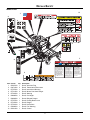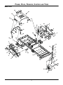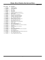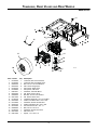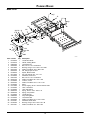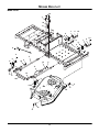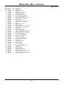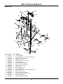
1
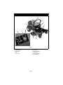
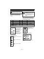
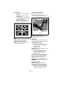
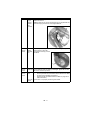
Zoom®
Owner/Operator Manual
Manuel Du Propriétaire/Utilisateur
Models
915131 – 1334
ENGLISH
FRANÇAIS
03770600A 2/09
Printed in USA
TABLE OF CONTENTS
SAFETY . . . . . . . . . . . . . . . . . . . . . . . . . 4
STORAGE . . . . . . . . . . . . . . . . . . . . . . 26
ASSEMBLY. . . . . . . . . . . . . . . . . . . . . . 10
TROUBLESHOOTING . . . . . . . . . . . . . 26
CONTROLS AND FEATURES . . . . . . . 12
SERVICE PARTS . . . . . . . . . . . . . . . . . 28
OPERATION . . . . . . . . . . . . . . . . . . . . . 13
ACCESSORIES . . . . . . . . . . . . . . . . . . 28
MAINTENANCE SCHEDULE . . . . . . . . 16
SPECIFICATIONS . . . . . . . . . . . . . . . . 29
SERVICE AND ADJUSTMENTS . . . . . 18
WARRANTY . . . . . . . . . . . . . . . . . . . . . 30
INTRODUCTION
NON-ENGLISH MANUALS
THE MANUAL
Manuals in languages other than
English may be obtained from your
Dealer. Visit your dealer or
www.ariens.com for a list of
languages available for your
equipment.
Manuals printed in languages other
than English are also available as a
free download on our website:
Before operation of unit, carefully and
completely read your manuals. The contents
will provide you with an understanding of
safety instructions and controls during normal
operation and maintenance.
All reference to left, right, front, or rear are
given from operator seated in operation
position and facing the direction of forward
travel.
http://www.ariens.com
MODEL AND SERIAL NUMBERS
MANUALES EN IDIOMAS
DIFERENTES DEL INGLES
Puede obtener manuales en
idiomas diferentes del inglés en su
distribuidor. Visite a su distribuidor
o vaya a www.ariens.com para
obtener una lista de idiomas
disponibles para su equipo.
También puede imprimir manuales
en idiomas diferentes del inglés
descargándolos gratuitamente de
nuestra página Web:
When ordering replacement parts or making
service inquiries, know the Model and Serial
numbers of your unit and engine.
Numbers are located on the product
registration form in the unit literature
package. They are printed on a serial number
label, located on the frame of your unit under
the seat (figure 1).
http://www.ariens.com
Manuels non anglais
Des manuels dans différentes
langues sont disponibles chez
votre revendeur. Rendez-vous
chez votre revendeur ou allez sur
le site www.ariens.com pour
consulter la liste des langues
disponibles pour votre équipement.
Les manuels imprimés dans des
langues différentes de l’anglais
sont également disponibles en
téléchargement gratuit sur notre
site Web :
Unit Serial Number
Label
Figure 1
http://www.ariens.com
GB - 2
•
•
Record Unit Model and Serial
numbers here.
Before Attempting to Operate Your
Unit:
1. Make sure all assembly has been
properly completed.
2. Understand all Safety Precautions
provided in the manuals.
3. Review control functions and operation
of the unit. Do not operate the unit
unless all controls function as described
in this manual.
4. Review recommended lubrication,
maintenance and adjustments.
5. Review Limited Warranty Policy.
6. Fill out a product registration card and
return the card to the Ariens Company or
go to www.ariens.com.
Record Engine Model and Serial
numbers here.
PRODUCT REGISTRATION
The Ariens dealer must register the product
at the time of purchase. Registering the
product will help the company process
warranty claims or contact you with the latest
service information. All claims meeting
requirements during the limited warranty
period will be honored, whether or not the
product registration card is returned. Keep a
proof of purchase if you do not register your
unit.
Customer Note: If the Dealer does not
register your product, please fill out, sign and
return the product registration card to Ariens
or go to www.ariens.com on the internet
UNAUTHORIZED REPLACEMENT
PARTS
DISCLAIMER
Ariens reserves the right to discontinue,
change, and improve its products at any time
without notice or obligation to the purchaser.
The descriptions and specifications contained
in this manual were in effect at printing.
Equipment described within this manual may
be optional. Some illustrations may not be
applicable to your unit.
Use only Ariens replacement parts. The
replacement of any part on this unit with
anything other than an Ariens authorized
replacement part may adversely affect the
performance, durability, and safety of this unit
and may void the warranty. Ariens disclaims
liability for any claims or damages, whether
warranty, property damage, personal injury or
death arising out of the use of unauthorized
replacement parts.
NOTE: A complete Parts manual may be
download from www.ariens.com on the
internet
DELIVERY
Customer Note: If you have purchased this
product without complete assembly and
instruction by your retailer, it is your
responsibility to:
• Read and understand all assembly
instructions in this manual. If you do
not understand or have difficulty
following the instructions, contact your
nearest Ariens Dealer for assistance.
NOTE: To locate your nearest Ariens Dealer,
go to www.ariens.com on the internet.
WARNING: Improper assembly
or adjustments can cause serious
injury.
GB - 3
SAFETY
CAUTION: POTENTIALLY
HAZARDOUS SITUATION! If not
avoided, MAY RESULT in minor
or moderate injury. It may also be
used to alert against unsafe
practices.
WARNING: This cutting machine
is capable of amputating hands
and feet and throwing objects.
Failure to observe the safety
instructions in the manuals and on
decals could result in serious
injury or death.
Slopes are a major factor related
to loss-of-control and tip-over
accidents. Operation on all slopes
requires extra caution.
Tragic accidents can occur if the
operator is not alert to the
presence of children. Never
assume that children will remain
where you last saw them.
Gasoline is extremely flammable
and the vapors are explosive,
handle with care.
Disengage attachment, stop unit
and engine, remove key, engage
parking brake, and allow moving
parts to stop before leaving
operator’s position.
NOTATIONS
NOTE: General reference information for
proper operation and maintenance practices.
IMPORTANT: Specific procedures or
information required to prevent damage to
unit or attachment.
SAFETY DECALS AND
LOCATIONS
ALWAYS replace missing or damaged Safety
Decals. Refer to figure 2 for Safety Decal
locations.
SAFETY ALERTS
Look for these symbols to point
out important safety
precautions. They mean:
• Attention!
• Personal Safety Is
Involved!
• Become Alert!
• Obey The Message!
The safety alert symbol is used in decals and
with this manual. Understand the safety
message. It contains important information
about personal safety.
WARNING: POTENTIALLY
HAZARDOUS SITUATION! If not
avoided, COULD RESULT in
death or serious injury.
DANGER: IMMINENTLY
HAZARDOUS SITUATION! If not
avoided, WILL RESULT in death
or serious injury.
GB - 4
2
1
7
3
6
4
3
5
Figure 2
1.DANGER!
3.DANGER!
Always keep feet and hands
away from rotating parts.
Avoid injury - Stay clear of
rotating parts.
OL1816
OL1809
2.CAUTION
Always stand clear of discharge
area. Do not direct discharge
toward other people.
OL1810
No smoking.
Keep people away from unit
while operating.
OL18111
Do not overfill.
Fill fuel tank to below bottom of
filler neck.
•
•
Shut off engine, remove key,
and read manual before you
adjust or repair unit.
OL1812
Never fill fuel tank when engine is
running, hot or unit is indoors. Never
overfill fuel tank.
Replace fuel cap securely and clean
up spilled fuel.
NO STEP! Always keep feet
away from rotating parts.
OL1813
GB - 5
4.DANGER! TO AVOID SERIOUS
INJURY OR DEATH
5.WARNING!
Read the operator’s manual.
Always stand clear of discharge
area.
OL1814
OL1801
Keep children and others away
from unit while operating.
Do not operate mower unless
bagger is attached or guards
are in operating position.
OL1815
OL1802
Never direct discharge toward
other people. Thrown objects
can cause injury.
6.DANGER!
OL1803
Keep hands and feet away.
Look down and behind before
and while backing.
OL1804
Do not operate mower unless
guards are in operating position
or bagger is attached.
OL1805
Never carry children.
7.HOT SURFACES!
OL1806
10
MAX
OL1807
Go up and down slopes, not
across.
DO NOT operate on slopes
over 10°.
•
If machine stops going uphill, stop
blade and back down slowly.
•
Avoid sudden turns.
•
Keep safety devices (guards,
shields, switches, etc.) in place and
working.
•
Check interlock system per manual
before use.
•
Understand location and function of
all controls.
•
Never allow operation by untrained
persons.
•
Disengage PTO, stop unit and
engine, set parking brake and
remove key before making any
inspections, repairs, etc.
OL1801
DO NOT touch parts which are
hot from operation. ALWAYS
allow parts to cool.
EMISSION CONTROL SYSTEM
CERTIFICATION LABEL
Tampering with emission controls and
components by unauthorized personnel may
result in severe fines or penalties. Emission
controls and components can only be
adjusted by EPA and/or CARB authorized
service centers. Contact your Ariens
Equipment Retailer concerning emission
controls and component questions.
SAFETY RULES
If unit is to be used by someone other than
original purchaser; loaned, rented or sold,
ALWAYS provide this manual and any
needed safety training before operation.
Only the user can prevent and is responsible
for accidents or injuries occurring to
themselves, other people or property.
Read, understand, and follow all safety
practices in Owner/Operator Manual before
assembling, using or working on this mower.
GB - 6
ALWAYS remove key from ignition and wire
from spark plug before assembly, or working
on this unit.
Inspect unit before each use for: missing or
damaged decals and shields, correctly
operating safety interlock system, and
deterioration of grass catchers. Replace or
repair as needed.
ALWAYS check overhead and side
clearances carefully before operation.
ALWAYS be aware of traffic when crossing or
operating along streets or curbs.
Keep children, people, and pets away. Be
alert and shut off unit if anyone enters work
area. Keep children under watchful care of a
responsible adult.
NEVER allow children to operate or play on
or near unit.
Keep area of operation clear of all toys, and
debris. Thrown objects can cause injury.
Stay alert for hidden hazards, holes, and ruts.
Avoid uneven or rough terrain. DO NOT
operate near drop-offs, ditches, or
embankments. Unit can suddenly turn over if
a wheel is over the edge of a cliff or ditch, or if
an edge caves in.
Dust, fog, etc. can reduce vision and cause
an accident. Operate unit only when there is
good visibility and light.
Data indicates that operators, age 60 and
above, are involved in a larger percentage of
riding mower related injuries. These
operators should evaluate their ability to
operate the riding mower safely enough to
protect themselves and others from serious
injury.
Only trained adults may operate unit. Training
includes being familiar with controls and
actual operation.
NEVER operate unit after or during the use of
medication, drugs or alcohol.
NEVER allow anyone to operate this unit
when their alertness or coordination is
impaired.
Wear adequate safety gear, sturdy shoes,
and protective gloves.
DO NOT wear loose clothing or jewelry and
tie back hair that may get caught in rotating
parts.
Protect eyes, face and head from objects that
may be thrown from unit. Wear appropriate
hearing protection. Always wear safety
goggles or safety glasses with side shields
when operating mower.
Avoid sharp edges. Sharp edges can cut.
Moving parts can cut off fingers or a hand.
ALWAYS keep hands and feet away from all
rotating parts during operation. Rotating parts
can cut off body parts.
ALWAYS keep hands away from all pinch
points.
Start and operate unit only when seated in
operator’s position. Steering control levers
must be in neutral, PTO disengaged and
parking brake set when starting engine.
ALWAYS keep body and hands away from
pin holes or nozzles which eject hydraulic
fluid under pressure.
DO NOT touch unit parts which might be hot
from operation. Allow parts to cool before
attempting to maintain, adjust or service.
NEVER place your hands or any part of your
body or clothing inside or near any moving
part while unit is running.
NEVER direct discharge towards persons or
property. Thrown objects may ricochet back
towards operator. ALWAYS stand clear of the
discharge area.
ALWAYS disengage attachment, stop unit
and engine, remove key, engage parking
brake, and allow moving parts to stop before
leaving operator’s position.
Use extreme caution on gravel surfaces.
Disengage PTO when attachment is not in
use and when crossing gravel surfaces.
DO NOT operate unit if safety interlock
system is damaged or disabled. Check safety
interlock before each use.
ALWAYS remove key to prevent unauthorized
use.
DO NOT operate at too fast a rate. Slow
down before turning.
Stop engine before removing grass catcher or
unclogging chute.
DO NOT mow on wet grass. Reduced
traction could cause sliding.
DO NOT try to stabilize the machine by
putting your foot on the ground.
Know the weight of loads. Limit loads to those
you can safely control and the unit can safely
handle.
ALWAYS keep protective structures, guards
and panels in good repair, in place and
securely fastened.
Do not operate without either entire grass
catcher or the discharge guard in place.
DO NOT operate in reverse unless absolutely
necessary. ALWAYS look down and behind
before and while backing; especially for
children.
GB - 7
Follow the manufacturer’s recommendations
for wheel weights or counterweights to
improve stability when using attachments.
NEVER carry passengers–especially
children–even with blades off.
Use extra care when approaching blind
corners or objects that may obscure vision of
hidden obstacles and children.
If you cannot back up a slope or you feel
uneasy on it, do not mow it.
Mow up and down slopes, not across them.
Use slow speed on any slope. Tires may lose
traction on slopes even though the brakes are
functioning properly.
Keep all movements on the slope slow and
gradual. DO NOT make sudden changes in
speed or direction.
Use extra care while operating machines with
grass catcher or other attachments. They can
affect stability of the machine.
Avoid starting, stopping, or turning on a
slope. If tires lose traction, disengage the
blades and proceed slowly straight down the
slope.
DO NOT operate on slopes over 10°.
DO NOT park on slopes unless necessary. If
unit is parked on a slope, ALWAYS chock or
block wheels and set parking brake.
DO NOT disengage or bypass transmission
and coast downhill.
Tow only with a machine that has a hitch
designed for towing. Do not attach towed
equipment except at the hitch point.
Follow the manufacturer’s recommendations
for weight limits for towed equipment and
towing on slopes.
Maximum Tongue weight: 30 lbs.
Maximum Trailer weight: 300 lbs.
Do not use hitch with bagger attached.
Do not use on steep hills or slopes.
Do not park on hills when trailer is attached.
Do not use with any ground engaging
equipment.
NEVER allow children or others in or on
towed equipment.
On slopes, the weight of the towed equipment
may cause loss of traction and loss of control.
Travel slowly and allow extra distance to stop.
Use extra care when loading or unloading
unit onto trailer or truck.
Secure unit chassis to transport vehicle.
NEVER secure from rods or linkages that
could be damaged.
DO NOT transport machine while engine is
running.
ALWAYS turn off power to attachment and
shut off fuel when transporting unit.
Keep unit free of grass clippings, leaves, and
other debris. Clean up oil or fuel spills.
This product is equipped with an internal
combustion type engine. DO NOT use unit on
or near any unimproved, forest-covered or
brush covered land unless exhaust system is
equipped with a spark arrester meeting
applicable local, state or federal laws. A spark
arrester, if it is used, must be maintained in
effective working order by operator.
Fuel is highly flammable and its vapors are
explosive. Handle with care. Use an
approved fuel container.
NO smoking, NO sparks, NO flames.
ALWAYS allow engine to cool before
servicing.
NEVER fill fuel tank when engine is running
or hot from operation.
NEVER fill or drain fuel tank indoors.
NEVER overfill fuel tank.
Replace fuel cap securely and clean up
spilled fuel.
NEVER fill containers inside a vehicle or on a
truck or trailer bed with a plastic liner. Always
place containers on the ground away from
your vehicle before filling.
When practical, remove gas-powered
equipment from the truck or trailer and refuel
it on the ground. If this is not possible, then
refuel such equipment on a trailer with a
portable container, rather than from a
gasoline dispenser nozzle.
Keep the nozzle in contact with the rim of the
fuel tank or container opening at all times until
fueling is complete. Do not use a nozzle lockopen device.
If fuel is spilled on clothing, change clothing
immediately.
Avoid Electric Shock. Objects contacting both
battery terminals at the same time may result
in injury and unit damage. DO NOT reverse
battery connections.
Explosive Gases from battery can cause
death or serious injury. Poisonous battery
fluid contains sulfuric acid and its contact with
skin, eyes or clothing can cause severe
chemical burns.
NO flames, NO sparks, NO smoking near
battery.
ALWAYS wear safety glasses and protective
gear near battery. Use insulated tools.
GB - 8
DO NOT TIP battery beyond a 45° angle in
any direction.
ALWAYS keep batteries out of reach of
children.
Battery posts, terminals and related
accessories contain lead and lead
compounds, chemicals known to the State of
California to cause cancer and reproductive
harm. Wash hands after handling.
Reverse connections may result in sparks
which can cause serious injury. Always
connect positive (+) lead of charger to
positive (+) terminal, and negative (-) lead to
negative (-) terminal.
ALWAYS disconnect negative (-) cable FIRST
and positive (+) cable SECOND. ALWAYS
connect positive (+) cable FIRST, and
negative (-) cable SECOND.
A frozen battery can explode and result in
death or serious injury. DO NOT charge or
jump start a battery containing frozen fluid.
Thaw the battery before putting on a charger
or jump starting.
ALWAYS keep protective structures, guards,
and panels in good repair, in place and
securely fastened. NEVER modify or remove
safety devices.
DO NOT change engine governor settings or
over-speed engine.
Fumes from engine exhaust can cause injury
or death. DO NOT run engine in an enclosed
area. Always provide good ventilation.
ALWAYS maintain unit in safe operating
condition. Damaged or worn out muffler can
cause fire or explosion.
Stop and inspect equipment if you strike an
object or if there is an unusual vibration.
Repair, if necessary, before restarting. Never
make adjustments or repairs with the engine
running.
Mower blades are sharp and can cut you.
Wrap the blade(s) or wear gloves, and use
extra caution when servicing them. NEVER
weld or straighten mower blades.
Rotation of one blade may cause rotation of
the other blades.
Check brake operation frequently. Adjust and
service as required.
Keep all hardware properly tightened.
Stored energy in springs can cause injury.
Maintain or replace safety and instruction
labels, as necessary.
Never store the machine or fuel container
inside a building where there is an open
flame, such as a water heater.
Shut off fuel (if provided) and allow engine to
cool completely before storing in closed area
or covering unit.
Clean grass and debris from unit, especially
from around muffler and engine, to help
prevent fires.
For extended storage, clean unit thoroughly.
See Engine Manual for proper storage.
Use only attachments or accessories
designed for your unit.
Check attachment components frequently. If
worn or damaged, replace with
manufacturer’s recommended parts.
GB - 9
ASSEMBLY
WARNING: AVOID INJURY.
Read and understand the entire
Safety section before proceeding.
1
Tools Required
•
•
Adjustable wrench
Petroleum jelly or dielectric grease.
Unpack Unit
Remove unit and all other components from
the shipping container. Engage transmission
bypass lever (see MOVING UNIT
MANUALLY on page 15). Push unit from
container onto a level surface. Disengage
transmission bypass lever.
2
Connect Battery
3
See Battery Removal and Installation on
page 22 and perform steps 2 and 3 in the
installation section.
Place Unit in Operating Position
(Figure 3):
1
NOTE: The seat is shipped with the seat
positioned as far back as possible.
1. Tip seat forward and adjust the seat as
needed (see TIPPING SEAT
FORWARD on page 18 and SEAT
ADJUSTMENT on page 18).
2. Remove eccentric spacers and rotate
steering levers to the operating position.
Reinstall spacers. Do not tighten.
3. Adjust steering levers (see ADJUSTING
STEERING LEVERS on page 23).
1. Steering Lever
2. Seat
3. Eccentric
Spacer
Figure 3
Check Engine Oil Level
Refer to Engine Manual.
GB - 10
Check Tire Pressure
CAUTION: Avoid injury!
Explosive separation of tire and
rim parts is possible when they
are serviced incorrectly:
• Do not attempt to mount a
tire without the proper
equipment and experience
to perform the job.
• Do not inflate the tires
above the recommended
pressure.
• Do not weld or heat a
wheel and tire assembly.
Heat can cause an
increase in air pressure
resulting in an explosion.
Welding can structurally
weaken or deform the
wheel.
• Do not stand in front or
over the tire assembly
when inflating. Use a clipon chuck and extension
hose long enough to allow
you to stand to one side.
Level Mower Deck
See LEVELLING AND ADJUSTING PITCH
OF MOWER DECK on page 20.
Fill Fuel Tank
See FILLING FUEL TANK on page 14.
Check Safety Interlock System
WARNING: Safety interlock
failure and improper operation of
unit can result in death or serious
injury. Check system before each
use to make sure it is functioning
properly.
See Safety Interlock System on page 13.
Check function of all controls
See OPERATION on page 13.
See SPECIFICATIONS on page 29.
GB - 11
CONTROLS AND FEATURES
6
4
7
5
11
8
1
2
3
10
9
Figure 4
1. Throttle/Choke Lever
2. Ignition Switch
3. PTO Switch
4. Seat
5. Fuel Level
6. Steering Levers
7. Fuel Tank
8. Mower Lift Pedal
9. Mower Deck
10. Discharge Chute
11. Parking Brake
GB - 12
OPERATION
Safety Interlock System
WARNING: AVOID INJURY.
Read and understand the entire
Safety section before proceeding.
WARNING: Safety interlock failure
and improper operation of unit can
result in death or serious injury.
Check system before each use to
make sure it is functioning
properly.
CONTROLS AND FEATURES
See figure 4 for all controls and features
locations.
Perform the following tests to ensure the
safety interlock system is working properly. If
the unit does not perform as stated contact
your Ariens dealer for repairs.
Test
Steering Lever
1
Neutral Position
2
Neutral Position
3
Neutral Position
4*+
Out of Neutral Position
5*+
Neutral Position
* Test with engine running.
+ Operator lifts off seat.
PTO
Off
On
Off
Off
On
Ignition Switch
Parking Brake
Engaged
Engaged
Disengaged
Disengaged
Engaged
Engine
Starts
Doesn’t Start
Doesn’t Start
Shuts Off
Shuts Off
Parking Brake
Operate ignition switch
with a removable key.
Ignition switch has three
positions: Stop (1),
Run (2), Start (3). See
STARTING AND
SHUTTING OFF
ENGINE on page 14 for
detailed instructions on
how to start engine.
1
Engages (2) and
disengages (1) parking
brake.
2
Power Take-Off (PTO) Switch
1
Throttle/Choke Lever
Choke (1) – Use to start a cold
engine.
1
2
2
Fast (2) – Increases engine
speed.
Engages (2) and disengages (1) mower
blades.
Slow (3) – Decreases engine
speed.
3
OE0002
GB - 13
Steering Levers
•
•
•
•
1
3
Mower Lift Pedal (Figure 5)
Reverse (1) – Pull both steering levers
backward.
Forward (2) – Push both steering
levers forward.
Left (3) – Pull left steering lever back
or push right steering lever forward or
a combination of both.
Right (4) – Pull right steering lever
back or push left steering lever
forward or a combination of both.
Raises and lowers mower deck.
Press mower lift pedal and install adjustment
pin in the desired adjustment hole.
3
1
2
2
1. Mower Lift
Pedal
2. Adjustment
Hole
3. Adjustment Pin
4
Figure 5
NOTE: To stop, return both steering levers to
neutral.
NOTE: The steering levers must be in the
neutral position to start the engine.
NOTE: The parking brake must be
disengaged prior to moving the steering
levers from the neutral position.
NOTE: The adjustment pin is used to set the
height of the mower deck. See
SPECIFICATIONS on page 29 for cutting
height dimensions.
Fuel Level
Slot in seat plate shows the fuel level in the
tank. Refill when level gets to bottom of slot.
FILLING FUEL TANK
1. Clean fuel cap and surrounding area to
prevent dust, dirt, and debris from
entering fuel tanks.
2. Remove fuel cap.
IMPORTANT: See Engine Manual for correct
type and grade of fuel.
3. Fill fuel tank to below bottom of filler
neck. See SPECIFICATIONS on
page 29 for capacity of fuel tanks.
4. Replace fuel cap.
STOPPING IN AN EMERGENCY
Bring steering levers back to neutral, set
parking brake, and turn off engine.
STARTING AND SHUTTING OFF
ENGINE
Starting the Engine
NOTE: Disengage the PTO, place the
steering levers in neutral, and engage the
parking brake prior to starting the engine.
1. If the engine is cold, move the choke
control to the On position. If the engine
is warm or hot, do not use choke.
GB - 14
IMPORTANT: DO NOT operate starter for
more than 10 seconds per minute as damage
can occur.
2. Put the ignition key in the switch and
turn it to the Start position.
3. As soon as the engine starts, release the
key.
4. Move the choke control to the Off
position from the Choke position. Wait
until the engine is running smoothly
before operation.
IMPORTANT: Let the engine warm up
several seconds to several minutes
depending on outside temperature.
Stopping the Engine
1. Stop unit.
2. Disengage PTO.
3. Set throttle lever to slow.
4. Turn ignition switch to off position and
remove key.
5. Set parking brake.
Vary cutting pattern with each mowing.
Do not allow grass or debris to collect inside
of mower deck. Clean after each use.
MOVING UNIT MANUALLY
WARNING: DO NOT disengage
or bypass transmission and coast
downhill.
Pull the bypass lever out and lock it in place,
and then release the parking brake to push
the unit by hand.
Push the lever in to drive the unit normally.
NOTE: There are two bypass levers; one on
each side of the unit.
1
OPERATING MOWER
1. Start engine.
2. Set throttle lever to fast.
IMPORTANT: Never engage PTO if mower is
plugged with grass or other material.
3. Engage PTO to start mower blades. It
will take 2–3 seconds for the blades to
engage.
NOTE: The parking brake must be
disengaged prior to moving the steering
levers from the neutral lockout position.
4. Release parking brake.
5. Use steering levers to move the unit.
6. Disengage PTO to stop mower blades.
TRANSPORTING UNIT
ALWAYS shut off engine, set parking brake,
remove key, and drain fuel when transporting
unit on a truck or trailer. Tie unit down
securely. Do not tie down by linkages,
guards, cables or other parts that may be
damaged.
2
FOR BEST PERFORMANCE
Cut grass when it is dry.
Keep mower blades sharp.
Keep mower deck properly leveled.
Do not set height of cut too low. For very tall
grass, mow twice.
Do not travel too fast.
Mow with the engine set at full throttle.
When mulching, only remove 1/3 of grass
length per cutting.
Discharge clippings into areas already cut.
GB - 15
1. Bypass lever pulled out to push
the unit by hand.
2. Bypass lever pushed in to drive
the unit.
Figure 6
MAINTENANCE SCHEDULE
WARNING: AVOID INJURY. Read
and understand the entire Safety
section before proceeding.
Interval
Task
Each Use
Check
Safety
Interlock
System
IMPORTANT: Proper maintenance can
prolong the life of unit. The following chart
shows the recommended service schedule.
Refer to the maintenance instructions in the
Engine Manual for additional information.
NOTE: To have full access to the engine, the
seat must be tipped forward (see TIPPING
SEAT FORWARD on page 18) and the hood
opened (see MOWER DECK REMOVAL
AND INSTALLATION on page 18).
Action
WARNING: Safety interlock system failure and improper
operation of unit can result in death or serious injury. Test
this system each time the unit is operated. If this system
does not function as described, do not operate until repairs
are made (see Safety Interlock System on page 13).
Check
Engage parking brake and engage transmission bypass lever (see
Parking
MOVING UNIT MANUALLY on page 15). Push unit. If unit rolls, contact
Brake
your Ariens Dealer.
Clean Unit Clean engine, battery, seat, mower deck, etc. of all dirt and debris. Do
not use solvents, hard cleaners, or abrasives.
NOTE: Protect painted surfaces with automotive type wax.
Check
See SPECIFICATIONS on page 29 for correct tire pressure.
Tires
CAUTION: Avoid injury! Explosive separation of tire and rim
parts is possible when they are serviced incorrectly:
•Do not attempt to mount a tire without the proper equipment
and experience to perform the job.
• Do not inflate the tires above the recommended pressure.
• Do not weld or heat a wheel and tire assembly. Heat can cause
an increase in air pressure resulting in an explosion. Welding
can structurally weaken or deform the wheel.
• Do not stand in front or over the tire assembly when inflating.
Use a clip-on chuck and extension hose long enough to allow
you to stand to one side.
Check
Check for worn or damaged mower blades (see SHARPENING
Mower
MOWER BLADE on page 21).
Blades
GB - 16
Interval
Task
Action
Each Use
Follow
Engine
Manual
Maintenance
Schedule
Perform scheduled engine maintenance. Refer to Engine Manual for
detailed instructions.
NOTE: To drain the oil, use the oil drain petcock (1) supplied with unit,
not the drain plug that is shown in the Engine Manual.
Check
Battery
Lubricate
Unit
Keep battery and battery terminals clean (see Cleaning Battery and
Battery Cables on page 22).
Apply grease to zerk (1) on each
front wheel
25 Hours
or Every
Season
1
1
50 Hours
or Every
Season
100 Hours
or Every
Season
Check
Check mower blade mounting hardware and all other fasteners.
Fasteners Replace fasteners that are missing or damaged. Tighten all nuts and
bolts to the correct torque value.
Check All Replace worn or deteriorated belts.
Belts
• Check hydrostatic belt (see REPLACING HYDROSTATIC BELT
on page 25 for hydrostatic belt location).
• Check PTO belt (see REPLACING PTO BELT on page 24 for
PTO belt location).
Check All Replace worn or improperly functioning PTO cables.
Cables
GB - 17
SERVICE AND ADJUSTMENTS
WARNING: AVOID INJURY.
Read and understand the entire
Safety section before proceeding.
MOWER DECK REMOVAL AND
INSTALLATION
Remove (Figure 9)
1. Remove PTO belt from the engine drive
pulley (see REPLACING PTO BELT on
page 24).
2. Disconnect PTO actuator cable from the
cable anchor and deck idler arm.
TIPPING SEAT FORWARD
Put steering levers up and tip seat forward
(figure 7).
2
3
2
1
1. Cable Anchor
2. PTO Actuator Cable
3. Idler Arm
1. Seat Tipped Forward
2. Mounting Hardware
1
Figure 7
SEAT ADJUSTMENT
1. Tip the seat forward.
2. Loosen mounting hardware and slide
seat forward or backward to desired
position. Tighten mounting hardware
(figure 7).
3. Tip seat back.
Figure 8
NOTE: Perform steps 3 and 4 for the right
and left side of unit.
3. Disconnect drag link from the front deck
bracket.
4. Disconnect front and rear trunnions from
the lift arms.
5. Slide mower deck out from under unit.
GB - 18
Install (Figure 9)
5. Install PTO belt on the engine drive
pulley (see REPLACING PTO BELT on
page 24).
NOTE: Make sure the cable is taut, but not
tight. The cable needs a slight amount of
slack for the pulley brake to work correctly.
6. Level and adjust pitch of mower deck
(see LEVELLING AND ADJUSTING
PITCH OF MOWER DECK on page 20).
1. Slide mower deck under unit.
NOTE: Perform step 2 and 3 for the right and
left side of unit.
2. Connect drag link to front deck bracket.
3. Connect front and rear trunnions to lift
arms.
4. Connect the PTO actuator cable to the
deck idler arm and cable anchor.
3
1
4
2
5
6
7
1.
2.
3.
4.
PTO Actuator Cable
Drag Link
Front Deck Bracket
Front Trunnion
5. Deck Lift Arm
6. Mower Deck
7. Rear Trunnion
Figure 9
GB - 19
5
LEVELLING AND ADJUSTING
PITCH OF MOWER DECK
The Forward Pitch Of The Mower
Blades (Figure 11):
NOTE: Adjust on a level surface, with the
tires inflated to the correct air pressure (see
SPECIFICATIONS on page 29).
Three measurements are required to level
and adjust the pitch of the mower deck.
1. The distance from the mower blades to
the ground.
2. The forward pitch of the mower blades.
3. The pitch of the mower blades from
side-to-side.
•
Should be 0.0 in. (0.0 mm) to 1/4 in.
(6.35 mm) pitched forward.
NOTE: This measurement must be taken
when the mower blades ends point forward.
Forward Pitch of Mower Blades
3
1
2
The Distance From The Mower
Blades To The Ground (Figure 10):
•
•
In the lowest cutting position should be
1.5. in. + 1/4 in. (3.8 cm + 0.64 cm).
In the highest cutting position should
be 4.5 in. + 1/4 in. (11.4 cm + 0.64
cm).
Lowest Cutting Position
3
1
2
Forward Pitch = 0.0 in. (0.0 mm) to
1/4 in. (6.35 mm)
Front of Mower
Deck
1. Mower Deck
2. Mower Blade
3. Ground
Figure 11
The Pitch Of The Mower Blades From
Side-To-Side (Figure 12):
•
Should be within 1/4 in. (6.35 mm) as
measured on each side of the mower
deck.
NOTE: This measurement must be taken
when the mower blade ends point left and
right.
1.50 in. + 1/4 in. (3.8 cm + 0.64 cm)
Highest Cutting Position
Side-To-Side Pitch
3
1
2
3
1
2
4.50 in. + 1/4 in. (11.4 cm + 0.64 cm)
1. Mower Deck
2. Mower Blade
3. Ground
1/4-in. (6.35 mm) from Side-To-Side
1. Mower Deck
2. Mower Blade
Figure 10
3. Ground
Figure 12
GB - 20
Adjusting The Mower Deck To Adjust
Mower Blade Height And Pitch
(Figure 13):
1
2
NOTE: Adjusting the mower deck will adjust
the height and pitch of the mower blades.
1. Adjust the trunnions first and re-take the
three measurements required to level
and adjust the pitch of the mower deck.
These measurements are:
a. The distance from the mower
blades to the ground.
3
b. The forward pitch of the mower
blades.
4
c. The pitch of the mower blades
from side-to-side.
2. Repeat step 1 as needed until all three
measurements are within the tolerances
specified.
1.
2.
3.
4.
Figure 14
2
1
Spindle
Blade
Washer
5/8 in. Nut
SHARPENING MOWER BLADE
CAUTION: DO NOT sharpen
mower blade while on unit. An
unbalanced mower blade will
cause excessive vibration and
eventual damage to unit. Check
mower blade balance prior to
reinstalling mower blades.
NEVER weld or straighten mower
blades.
1. Trunnion
2. Mower Deck
Figure 13
REPLACING MOWER BLADE
Remove (Figure 14)
CAUTION: Mower blades are
sharp and can cut you. Wrap
the blades or wear gloves, and
use extra caution when
servicing them.
1. Block mower blades to prevent rotation.
2. Remove mounting hardware and mower
blades from spindles.
1. Remove mower blade from unit (see
REPLACING MOWER BLADE on
page 21).
Ariens recommends having mower blades
sharpened by a professional. Contact your
Ariens dealer.
Discard mower blade if (figure 15):
• more than 1/2 in. (1.27 cm) of metal is
removed.
• the air lift erosion area is eroded.
• the mower blade is bent or broken.
Do not change angle of cutting edge or round
the corner at the end of mower blade.
2. Sharpen mower blade by removing an
equal amount of material from each end
of mower blade.
Install (Figure 14)
1. Install mower blades on spindles with
mounting hardware.
2. Torque 5/8-inch nut to 92 to 130 lbf-ft
(125 to 176 N•m).
GB - 21
3. Check mower blade balance by sliding
mower blade on an unthreaded bolt. If
blade is balanced, it should remain in a
horizontal position. If either end of
mower blade moves downward, sharpen
the heavy end until mower blade is
balanced.
4. Install mower blade on unit (see
REPLACING MOWER BLADE on
page 21).
Battery Removal and Installation
Remove (Figure 16)
1. Tip seat forward (see TIPPING SEAT
FORWARD on page 18).
2. Disconnect negative (–) cable first, then
positive (+) cable.
3. Remove battery hold-down bracket and
battery from unit.
Install (Figure 16)
DO NOT Sharpen to this Pattern
1. Install battery on the unit with battery
hold-down bracket.
2. Connect positive (+) cable first, then
negative (–) cable.
3. Apply petroleum jelly or dielectric grease
to battery cable ends and terminals.
4. Tip seat back (see TIPPING SEAT
FORWARD on page 18).
Sharpen to this Pattern
Discard if
more than
1/2 in.
(1/27 cm)
1
2
4
3
2
1
1.
2.
3.
4.
5.
6.
Figure 15
SERVICING THE BATTERY
Positive (+) Terminal
Positive (+) Cable
Battery Hold-Down Bracket
Battery
Negative (–) Terminal
Negative (–) Cable
NOTE: Unit comes equipped with a
maintenance-free battery that requires no
regular maintenance except cleaning the
terminals.
WARNING: Battery posts,
terminals and related accessories
contain lead and lead
compounds, chemicals known to
the State of California to cause
cancer and reproductive harm.
Wash hands after handling.
5
6
1. Air Lift Erosion
2. Cutting Edge
Figure 16
Cleaning Battery and Battery Cables
(Figure 16)
1. Tip seat forward (see TIPPING SEAT
FORWARD on page 18).
2. Disconnect negative (–) cable first, then
positive (+) cable.
3. Clean battery cable ends, negative (–)
terminal, and positive (+) terminal with a
wire brush and rinse with a weak baking
soda solution.
4. Connect positive (+) cable first, then
negative (–) cable.
5. Apply petroleum jelly or dielectric grease
to battery cable ends and terminals.
GB - 22
ADJUSTING STEERING LEVERS
6. Tip seat back (see TIPPING SEAT
FORWARD on page 18).
Adjusting Steering Lever Height
(Figure 17)
Charging the Battery
(Figure 16)
WARNING: FROZEN
BATTERIES CAN EXPLODE and
result in death or serious injury.
DO NOT charge a frozen battery.
Let the battery thaw before
charging.
2
Follow First Aid directions for contact with
battery fluid.
• External Contact: Flush with water.
• Eyes: Flush with water for at least 15
minutes and get medical attention
immediately!
• Internal Contact: Drink large quantities
of water. Follow with Milk of Magnesia,
beaten egg or vegetable oil. Get
medical attention immediately!
• In case of internal contact, DO NOT
induce vomiting!
IMPORTANT: DO NOT fast charge. Charging
at a higher rate will damage or destroy
battery.
IMPORTANT: ALWAYS follow information
provided on battery and battery charger.
Contact battery and battery charger
manufacturers’ for detailed instructions.
1. Remove battery from unit (see Battery
Removal and Installation on page 22).
2. Place battery in a well-ventilated area.
3. Connect positive (+) lead of charger to
positive (+) terminal, and negative (–)
lead of charger to negative (–) terminal.
4. Charge battery according to battery
charger and battery manufacturers’
instructions.
5. Install battery on unit (see Battery
Removal and Installation on page 22).
5
1
4
3
1.
2.
3.
4.
5.
Handlebar
Steering Lever
Mounting Hardware
Adjustment Holes
Eccentric Spacer
Figure 17
Jump-Starting
Ariens does not recommend jump-starting
your unit. Jump-starting can damage engine
and electrical system components. See your
engine manual for more detailed information.
NOTE: Perform steps 1 and 2 for both
steering levers.
1. Remove mounting hardware and move
handlebar up or down until the steering
levers are at the appropriate height.
2. Install mounting hardware.
NOTE: Align handlebars by adjusting
eccentric spacer until the height of
handlebars are the same.
GB - 23
Forward Speed Adjustment
REPLACING PTO BELT
(Figure 18)
Remove (Figure 19)
NOTE: Reverse speed cannot be adjusted. If
unit tracks excessively left or right in reverse,
see your Dealer for repair.
IMPORTANT: The unit should track within 2
feet (0.61 m) of a straight line for 30 feet
(9.14 m).
The travel of the steering levers may need
adjustment if the unit turns to the right or left
when both steering levers are pushed as far
forward as possible.
NOTE: The side the unit turns toward
indicates that the wheel on that side is turning
slower than the other wheel. Either the wheel
that is turning faster needs to slow down or
the wheel that is turning slower needs to
speed up to allow the unit to travel in a
straight line.
1. Determine which way the unit turns.
2. Loosen jam nut on the adjustment bolt.
3. Adjust speed by:
• Turning adjustment bolt clockwise to
decrease steering lever travel.
• Turning adjustment bolt
counterclockwise to increase steering
lever travel.
4. Tighten the jam nut.
1. Lower mower deck to the ground.
2. Remove belt covers from mower deck.
CAUTION: Use care when
releasing idler spring tension.
Keep body parts well away from
idler when performing this
operation.
3. Disconnect the PTO actuator cable from
the deck idler arm.
4. Pull idler arm towards outside of unit
until tension is removed from PTO belt.
5. Remove PTO belt from left mower deck
pulley.
6. Slowly release idler arm until tension is
removed from idler spring.
7. Remove PTO belt from mower deck and
engine drive pulley.
1
2
2
1
4
5
3
1.
2.
3.
4.
5.
2
1. Forward Travel Adjustment Bolt
2. Steering Lever
PTO Actuator Cable
Deck Spindle
Engine Drive Pulley
Deck Idler
PTO Belt
Figure 19
Figure 18
GB - 24
Install (Figure 19)
NOTE: Do not install PTO belt on left mower
deck pulley in step 1.
1. Install PTO belt on engine drive pulley
and mower deck.
2. Pull idler arm towards outside of unit
until PTO belt can be routed around left
mower deck pulley.
3. Slowly release idler arm until idler pulley
rests firmly against PTO belt.
4. Connect the PTO actuator cable to the
deck idler arm.
5. Insert a shim of 0.10" (the thickness of
12-gauge steel) between the roller on
the idler arm and the deck sheave. With
the shim in place, pull the actuator cable
taut and then tighten the cable
adjustment nuts against the cable mount
bracket to hold the setting.
6. Remove the shim and check for a gap
between the roller and the deck sheave.
7. Install belt covers on mower deck.
NOTE: Ensure that belt is still positioned in
the groove of the sheave after belt covers are
installed.
1
2
4
2
3
1. Hydrostatic Belt
2. Hydrostatic
Transmission
Pulley
REPLACING HYDROSTATIC BELT
Remove (Figure 20)
1. Remove PTO belt (see REPLACING
PTO BELT on page 24).
CAUTION: Use care when
releasing idler spring tension.
Keep body parts well away from
idler when performing this
operation.
2. Disconnect idler spring.
3. Remove hydrostatic belt from
hydrostatic transmission pulleys, pulley,
electric clutch, and idler.
Install (Figure 20)
1. Install hydrostatic belt on idler, electric
clutch, pulley, and hydrostatic
transmission pulleys.
2. Connect idler spring.
3. Install PTO belt (see REPLACING PTO
BELT on page 24).
GB - 25
3. Idler
4. Idler Spring
Figure 20
STORAGE
Short Term Storage
Fuel System
IMPORTANT: NEVER clean unit with highpressure water or store unit outdoors.
Remove all dirt, grease, leaves, etc. Store in
a clean dry area.
Inspect unit for signs of wear or damage.
Ensure all fasteners are properly tightened.
Gasoline left in the fuel system for extended
periods without a stabilizer will deteriorate,
resulting in gum deposits in the system.
These deposits can damage the carburetor
and the fuel hoses, filter and tank. Prevent
deposits from forming in the fuel system
during storage by adding a quality fuel
stabilizer to the fuel. Follow the
recommended mix ratio found on the fuel
stabilizer container.
To treat the fuel system for storage:
1. Add fuel stabilizer (Ariens part number
00592900) according to
manufacturers’s instructions.
Long Term Storage
Follow all instructions under Short Term
Storage.
Remove and fully charge battery. Store in a
clean dry area.
Drain fuel from fuel tank.
Refer to Engine Manual for the proper engine
storage procedures.
Touch up all scratched or chipped paint
surfaces.
2. Run engine for at least 10 minutes after
adding stabilizer to allow it to reach the
carburetor.
NEVER store the engine with fuel in the fuel
tank inside of a building with potential
sources of ignition.
TROUBLESHOOTING
PROBLEM
Engine will not
crank/start.
Engine runs
rough.
PROBABLE
CAUSE
CORRECTION
1. Safety interlock
system is not
engaged or is
faulty.
1. Check safety interlock system (see Safety
Interlock System on page 13).
2. Fuel tank empty.
2. Fill fuel tank (see FILLING FUEL TANK on
page 14).
3. Discharged
battery.
3. Charge battery (see Charging the Battery
on page 23).
4. Poor connection
between battery
and battery
cables.
4. Tighten battery cables and/or clean battery
and battery cables (see Cleaning Battery
and Battery Cables on page 22).
5. Spark plug wire(s)
loose or spark
plug(s) faulty.
5. Connect spark plug wire(s) or replace spark
plug(s). Refer to Engine Manual for detailed
instructions.
6. Faulty electrical
system.
6. Contact your Ariens Dealer.
7. Faulty engine.
7. Contact your Ariens Dealer.
1. Choke engaged.
1. Disengage choke.
2. Air filter cartridge
plugged.
2. Clean or replace air filter cartridge. Refer to
Engine Manual for detailed instructions.
3. Faulty engine.
3. Contact your Ariens Dealer.
GB - 26
PROBLEM
PROBABLE
CAUSE
CORRECTION
Unit does not
move with
engine running
when using
steering levers.
1. The transmission
bypass lever is
engaged.
1. Disengage transmission bypass lever (see
MOVING UNIT MANUALLY on page 15).
2. Faulty hydrostatic
belt.
2. Replace hydrostatic belt (see REPLACING
HYDROSTATIC BELT on page 25).
3. Faulty
transmission.
3. Contact your Ariens Dealer.
1. Operator
presence switch
not depressed.
1. Depress operator presence switch by sitting
on seat.
2. Faulty operator
presence switch.
2. Contact your Ariens Dealer.
3. Clutch actuator is
loose or
disconnected.
3. Connect wiring to PTO actuator.
Properly connect PTO actuator cable to the
deck cable anchor or to deck idler arm.
4. Faulty PTO belt.
4. Replace PTO belt (see REPLACING PTO
BELT on page 24).
5. Faulty PTO
switch, wires,
connectors, or
clutch.
5. Contact your Ariens Dealer.
1. Engine oil level
low.
1. Add engine oil. Refer to Engine Manual for
detailed instructions.
2. Cooling system
plugged.
2. Clean cooling system. Refer to Engine
Manual for detailed instructions.
PTO or mower
blades do not
engage or shut
off.
Engine
overheats.
3. Faulty engine.
3. Contact your Ariens Dealer.
Unit moves with
engine off and
parking brake
engaged.
1. The parking brake
needs
adjustment.
1. Contact your Ariens Dealer.
2. Faulty parking
brake.
2. Contact your Ariens Dealer.
Unit does not
travel in a
straight line.
1. Incorrect tire
pressure.
1. Check tire pressure (see SPECIFICATIONS
on page 29).
2. Steering levers
need adjustment.
2. Adjust steering levers (see Forward Speed
Adjustment on page 24)
3. Hydrostatic
transmission
and/or linkage
needs
adjustment.
3. Contact your Ariens Dealer.
Unit creeps with
steering levers
in neutral
position.
1. Hydrostatic
transmission
and/or linkage
needs
adjustment.
1. Contact your Ariens Dealer.
Poor cutting
quality.
1. Mower deck not
level or mower
pitch is incorrect.
1. Level and adjust pitch of mower deck (see
LEVELLING AND ADJUSTING PITCH OF
MOWER DECK on page 20).
2. Dull or faulty
mower blades.
2. Sharpen mower blades (see SHARPENING
MOWER BLADE on page 21) or replace
mower blades (see REPLACING MOWER
BLADE on page 21).
GB - 27
SERVICE PARTS
ACCESSORIES
Be sure to always use genuine Ariens parts
to keep your unit running like new.
See your authorized Ariens dealer to add
these optional accessories to your unit.
Part No.
Description
Part No.
Qty
Qty
Description
51519500
1
Spindle Assembly
71503300
1
36-Inch Roller
07100801
1
Front Wheel
71503400
1
48-Inch Dethatcher
07200116
1
HA Wrapped Belt Deck
71503600
1
Spreader
71508200
1
48-Inch Aerator
71510500
1
Steering Lever
Extender
07200010
1
HA Raw Laminated
Belt - Hydraulic Drive
03746500
1
34-Inch Mower Blade
03797300
1
34-Inch Mulching
Blade
71510800
1
34-Inch Mulch Kit
71510900
1
Trailer Hitch Kit
81503100
1
34-Inch Non-Powered
Bagger
GB - 28
SPECIFICATIONS
Model Number
915131
Model
Zoom 1334
Engine
Type
Briggs & Stratton IC
21 (344)
3
Engine Displacement in. (cc)
Governed RPM (May be
different from maximum RPM)
3600 + 0
3600 – 100
Speed
Forward Max. – m.p.h (km/h)
6.0 (9.6)
Reverse Max. – m.p.h (km/h)
3 (4.8)
Turning Radius
Zero
Brakes
Internal Transmission
Electrical
Starter
Electric
Battery
12V Maintenance Free SLI U1B 165
PTO (Power Take-Off)
Cable Actuator
Fuel
Fuel Type
Refer to Engine Manual
Fuel Tank Capacity – gal. (L)
2.5 (9.5)
Transmission
Hydrostatic Drive
Size and Weight
Length – in. (cm)
65 (165.1)
Width – in. (cm)
45 (114.3)
Weight – lbs (kg)
420 (190.5)
Height – in. (cm)
40 (102)
Tires
Front Tire Size – in.
4 x 11
Rear Tire Size – in.
18 x 6.5 x 8
Front Tire Pressure – psi (kPa)
46 (317)
Rear Tire Pressure – psi (kPa)
12 (82.7)
Mower Deck
Cutting Height – in. (cm)
1.5 – 4.5 (3.8 – 11.4)
Cutting width – in. (cm)
34 (86)
Max. Towing Capacity – lbs (kg)
300 (136)
Max. Tongue Weight – lbs (kg)
30 (13.6)
GB - 29
Two-Year Limited Lawn and
Garden Consumer Ride-On
Warranty
Ariens Company (Ariens) warrants to the original purchaser that Ariens and Gravely brand consumer
products manufactured and sold by Ariens after December 31, 2007 will be free from defects in material and
workmanship for a period of two years after the date of purchase. An authorized Ariens dealer (Ariens brand
products) or Gravely dealer (Gravely brand products) will repair any defect in material or workmanship, and
repair or replace any defective part, subject to the conditions, limitations and exclusions set forth herein.
Such repair or replacement will be free of charge (labor and parts) to the original purchaser except as noted
below.
Five-Year Limited Warranty on Mower Deck Shell
The deck shell on zero-turn riding mowers is warranted to the original purchaser for five years from
the date of purchase. Any defect in material or workmanship of the deck shell will be repaired free of
charge (parts and labor) to the original purchaser for two years after the date of purchase. For the third
through fifth year from the date of purchase, the parts required to repair a defect in material or workmanship of the deck shell, not the labor, will be provided free of charge.
Five-Year Limited Warranty on Main Frame
The main frame on zero-turn riding mowers is warranted to the original purchaser for five years from
the date of purchase. Any defect in material or workmanship of the main frame will be repaired free of
charge (parts and labor) to the original purchaser for two years after the date of purchase. For the third
through fifth year from the date of purchase, the parts required to repair a defect in material or workmanship of the main frame, not the labor, will be provided free of charge.
90-Day Limited Warranty on Service Parts and Accessories
Genuine Ariens or Gravely brand service parts and accessories are warranted to be free from defects
in material and workmanship for a period of 90 days after the date of purchase. An authorized Ariens or
Gravely dealer will repair or replace any such part or accessory free of charge, except for labor, during
that period.
The duration of all warranties herein applies only if the product is put to personal use around a household or
residence. If the product is put to any business use, agricultural, commercial, or industrial, then the duration
of these warranties shall be 90 days after the date of purchase. If any product is rented or leased, then the
duration of these warranties shall be 90 days after the date of purchase.
Exceptions, Limitations, Exclusions
Customer Responsibilities
Register the product immediately at the time of sale. If the dealer does not register the product, the
customer must complete the product registration card in the literature package and return it to the Ariens
Company, or register the unit online at www.ariens.com or www.gravely.com.
To obtain warranty service, the original purchaser must:
• Perform the maintenance and minor adjustments explained in the owner’s manual.
• Promptly notify Ariens or an authorized Ariens or Gravely service representative of the need for
warranty service.
• Transport the product to and from the place of warranty service.
• Have the warranty service performed by an authorized Ariens or Gravely service representative.
To find an Ariens or Gravely authorized service representative, contact Ariens at:
655 W. Ryan Street
Brillion, WI 54110
(920) 756 - 2141
www.ariens.com
www.gravely.com
ARIENS COMPANY
2YRCON-2008
GRAVELY® | STENS® | LOCKE® | NATIONAL® MOWER | BYNORM® | EVERRIDE® | GREAT DANE® 30
Exceptions and Limitations
•
Batteries are warranted only for a period of 12 months after date of purchase, on a prorated basis. For
the first 90 days of the warranty period, a defective battery will be replaced free of charge. If the
applicable warranty period is more than 90 days, Ariens will cover the prorated cost of any defective
battery, for up to 12 months after the date of purchase.
•
Engines and engine accessories are covered only by the engine manufacturer’s warranty and are not
covered by this warranty.
Eye-Q™ and Scan-Mate™ units are covered by their own warranty and are not covered by this
warranty.
Parts that are not genuine Ariens or Gravely service parts are not covered by this warranty.
The following maintenance, service and replacement items are not covered by this warranty unless
they are noted in the Limitations section above: lubricants, spark plugs, oil, oil filters, air filters, fuel
filters, brake linings, brake arms, shoes, runners, scraper blades, shear bolts, mower blades, mower
vanes, headlights, light bulbs, knives, cutters.
Any misuse, alteration, improper assembly, improper adjustment, neglect, or accident which requires
repair is not covered by this warranty.
This warranty applies only to products purchased in the United States (including Puerto Rico) and
Canada. In all other countries, contact place of purchase for warranty information.
Exclusions – Items Not Covered by This Warranty
•
•
•
•
•
Disclaimer
Ariens may from time to time change the design of its products. Nothing contained in this warranty shall be
construed as obligating Ariens to incorporate such design changes into previously manufactured products,
nor shall such changes be construed as an admission that previous designs were defective.
LIMITATION OF REMEDY AND DAMAGES
Ariens Company’s liability under this warranty, and under any implied warranty that may exist, is limited to
repair of any defect in workmanship, and repair or replacement of any defective part. Ariens shall not be
liable for incidental, special, or consequential damages (including lost profits). Some states do not allow the
exclusion of incidental or consequential damages, so the above limitation or exclusion may not apply to you.
DISCLAIMER OF FURTHER WARRANTY
Ariens Company makes no warranty, express or implied, other than what is expressly made in this
warranty. If the law of your state provides that an implied warranty of merchantability, or an implied
warranty of fitness for particular purpose, or any other implied warranty, applies to Ariens Company,
then any such implied warranty is limited to the duration of this warranty. Some states do not allow
limitations on how long an implied warranty lasts, so the above limitation may not apply to you.
This warranty gives you specific legal rights, and you may also have other rights which
vary from state to state.
ARIENS COMPANY
GRAVELY® | STENS® | LOCKE® | NATIONAL® | BYNORM® | EVERRIDE® | GREAT DANE®
Con_Ride_2008
31
Ariens Company
655 West Ryan Street
Brillion, WI 54110-1072
920-756-2141
Fax 920-756-2407
www.ariens.com
Zoom
Parts Manual
Models
915131 – 1334
03852900A 4/09
Printed in USA
THE MANUAL
PRODUCT REGISTRATION
Before you operate your unit, carefully and completely
read manuals supplied with the unit. The contents will
provide you with an understanding of safety instructions
and controls during normal operation and maintenance.
For your safety and the safety of others always read,
understand, and follow all DANGER, WARNING, and
CAUTION messages found in manuals and on safety
decals.
The Ariens dealer must register the product at the time of
purchase. Registering the product will help the company
process warranty claims or contact you with the latest
service information. All claims meeting requirements
during the limited warranty period will be honored,
whether or not the product registration card is returned.
Keep a proof of purchase if you do not register your unit.
Customer Note: If Dealer does not register your product,
please fill out, sign and return the product registration
card to Ariens or go to www.ariens.com.
Hardware descriptions are given in decimals.
Decimals to Fractions
.063
1/16
.563
9/16
.125
1/8
.625
5/8
.188
3/16
.688
11/16
.250
1/4
.750
3/4
.313
5/16
.813
13/16
.375
3/8
.875
7/8
.438
7/16
.938
15/16
.500
1/2
1.00
1
YOUR SATISFACTION IS IMPORTANT
Questions? Please follow these helpful steps:
1. Refer to the manuals supplied with your unit.
They will guide you through safe and proper
operation and maintenance.
They contain specifications on your unit.
If your questions are not answered in these manuals,
go to step number two.
2. Contact Your Dealer.
Our dealers will be happy to supply any service or
advice required to keep your unit operating at peak
efficiency.
A factory trained staff is available to support your
equipment needs. They stock genuine Ariens parts
and lubricants manufactured with the same precision
and skill as the original.
If your questions are not resolved by the support
staff, ask for the manager or owner.
When contacting your Dealer supply your model and
serial numbers.
SERVICE AND REPLACEMENT PARTS
When ordering replacement parts or making service
inquiries, know the Model and Serial numbers of your
unit and engine.
Numbers are located on the product registration card in
the unit literature package. They are printed on a serial
number label, located on the frame of your unit.
• Record Unit Model and Serial numbers here:
TO SPEED PARTS ORDERING:
1. Know the model and serial numbers of your unit.
• Record Engine Model and Serial numbers here:
2. Know the part number required.
3. Know the quantity required.
4. Know the part description.
UNAUTHORIZED REPLACEMENT PARTS
Use only Ariens replacement parts. The replacement of
any part on this vehicle with anything other than an
Ariens authorized replacement part may adversely affect
the performance, durability, or safety of this unit and may
void the warranty. Ariens disclaims liability for any claims
or damages, whether warranty, property damage,
personal injury or death arising out of the use of
unauthorized replacement parts.
2
MODELS
TABLE OF CONTENTS
Domestic
DECALS
Model 915131 (1334)
13hp Briggs & Stratton with 34” Mower
Serial No. 000101 and up
Decals . . . . . . . . . . . . . . . . . . . . . . . . . . . . . . . . . . . . 4
MAIN FRAME AND TRANSAXLES
Frame, Hood, Footrest, Caster and Tires . . . . . . . . . 6
Seat and Support . . . . . . . . . . . . . . . . . . . . . . . . . . . . 8
Transaxle, Dump Valves and Rear Wheels . . . . . . . . 9
OPERATOR CONTROLS
Parking Brake. . . . . . . . . . . . . . . . . . . . . . . . . . . . . . 10
Steering Controls . . . . . . . . . . . . . . . . . . . . . . . . . . . 12
FUEL TANKS AND ENGINE
Engine, Exhaust, Belt and Idlers . . . . . . . . . . . . . . . 14
Fuel Tank . . . . . . . . . . . . . . . . . . . . . . . . . . . . . . . . . 15
ELECTRICAL SYSTEM
Continuity Diagrams. . . . . . . . . . . . . . . . . . . . . . . . . 16
Electrical System . . . . . . . . . . . . . . . . . . . . . . . . . . . 17
Wiring Diagrams. . . . . . . . . . . . . . . . . . . . . . . . . . . . 19
MOWER DECKS
Mower Deck Lift . . . . . . . . . . . . . . . . . . . . . . . . . . . . 20
Mower Deck, Belt and Idlers . . . . . . . . . . . . . . . . . . 22
Belt Covers and Blades . . . . . . . . . . . . . . . . . . . . . . 24
3
© Copyright 2009 Ariens Company
DECALS-SAFETY
Model 915131
11
1
2
3
MAX. FILL
Max. Remplir
Máx. llene
03271900
07800029
10
077541
12
4
6
8
7
9
5
02988000
Item Part No.
1
2
3
4
5
6
7
8
9
10
11
12
05305100
03271900
07757600
07731400
07742300
02988000
02994800
07757500
07735200
07754100
07800029
05301400
Qty.
1
2
1
2
1
1
1
1
1
1
1
1
Description
Decal, American Flag
Decal, Transmission Disconnect
Decal, Instructional Steering
Decal, Mower Pan Head Danger
Decal, Warning
Decal, Cut Height
Decal, Bilingual Danger
Decal, Parking Brake Lever
Decal, Danger
Decal, Hot Surface
Decal, Fuel Warning
Decal, Control
4
TO AVOID SERIOUS
INJURY OR DEATH
POUR EVITER LES BLESSURES
GRAVES OU LA MORT
PARA EVITAR DANOS SERIOS
O LA MUERTE
Read the operator’s manual. Keep
children and others away from unit while
operating. Never direct discharge
toward other people. Thrown objects can
cause injury. Look down and behind
before and while backing. Never carry
children. Go up and Down slopes, not
across. If machine stops going uphill,
stop blade and back down slowly. Avoid
sudden turns. Keep safety devices
(guards, shields, switches, ect. ) in place
and working. Check interlock system
per manual before use. Understand
location and function of all controls.
Never allow operation by untrained
persons. Disengage PTO, stop unit and
engine, setparking brake and remove key
before making any inspections, repairs,
etc.
Regardez derriere et sur les cotes lorsque
vous reculez. Ne transportez jamais d’enfant.
Tondez toujours de haut en bas et inversement
jamais le long des pentes. Si la machines
s’arrete en montee. Debrayez le lame et
redescendez doucement. Evitez les virages
brusques. Maintenez toujours en place tous
les elements de securite (protecteus,
interrupteurs, etc.) Controler le bon
fonctionnement du systeme de securite avant
utilisation tel qu’indique dans le manuel
d’utilisation. Comprenez bien la fonction et la
situation de chacun des leviers et boutons de
commande. Ne jamais permettre l’utilisation
par des personnes n’ayant pas recu la formation
necessaire. Desenclencher la PdF, arreter la
machine et le moteur, serrer le frein de
stationnement et enlever la cle de contact avant
de commencer toute verification, reparation, etc.
Antes y durante retroceso mirar hacia abajo
y detras. Nunca monten ninos. Suba y baje
pendientes, no transversalmente. Si la
maquina se detiene subiendo cuesta,
desactive le cuchilla y beje lentamente. Evite
viradas subitas. Mantenga artefactos de
seguridad (defensas, protectores,
interruptores, etc.) en su lugar y trabajando.
Verifique en el manual el sistema de engranar
antes de usar. Tenga conocimiento de
funciones y localizaciones de todos los
controles. No permitir que personal sin la
necesaria formacion use la maquina.
Desactivar la TDF, detener a unidad, apagar
el motor, accionar el freno de estacionamiento
y quitar la llave antes de realizer cualquier
inspeccion, reparacion, etc.
02994800
DECALS-STYLE
Model 915131
3
1
6
8
2
5
4
7
PE0250
Item Part No.
1
2
3
4
5
6
7
8
07800037
07800036
08000229
07800032
07800033
07800035
07800034
07800111
Qty.
1
1
1
1
1
1
2
1
Description
Decal, Ariens Jewel
Decal, Zoom
Decal, Ariens Since 1933_Small
Decal, Soft Touch Clutch
Decal, Foot Pedal Lift
Decal, Powered By B&S
Decal, Deck Size 34”
Decal, 13hp
5
FRAME, HOOD, FENDERS, CASTERS AND TIRES
Model 915131
28
27
25
27
24
17
17
3
16
24
12
23
4
26
5
18
4
22
31
32
29
31
4
18
26
30
18
18
21
20
11
2
30
13
26
15
8
22
4
19
21
5
19
20
8
1
4
6
26
4
14
10
9
13
7
6
FRAME, HOOD, FENDERS, CASTERS AND TIRES
Model 915131
Item Part No.
1
2
3
4
5
6
7
8
9
10
11
12
13
14
15
16
17
18
19
20
21
22
23
24
25
26
27
28
29
30
31
32
03752551
03768600
03768700
06800106
03769000
03368551
07100801
05533600
00278500
05964400
03768851
03768951
06543600
05962200
06436400
06542000
07056700
07503100
00363100
08553700
06545500
06219900
03766559
06443300
03766459
07412900
06220600
03755000
06500012
07412000
06543500
07400035
Qty.
1
1
1
6
2
2
2
4
2
2
1
1
4
2
2
4
2
4
4
2
2
4
1
2
1
4
2
1
4
4
2
3
Description
Weldment, Frame
Fender, Right Hand
Fender, Left Hand
Rivet, Nylon
Plate, Fender
Fork, Caster
Wheel/Tire Assembly, 11.0 x 4.0 x 5.0
Bushing, Flange 1.00 x 1.25 x 1.50 x 1.50
Spacer, Wheel
Bolt, Hex .50-13 x 6.50 Grade 5
Weldment, Fender Mount Right Hand
Weldment, Fender Mount Left Hand
Nut, Locking-Top-Flange .50-13
Bolt, Hex .50-13 x 5.00 Grade 5
Washer, Flat Steel .511 x 1.441 x .125
Nut, Locking-Top-Flange .38-16
Bolt, Shoulder .375-16 x .135
Bumper Grommet .125 x .250 Diameter
Spacer, Caster
Bushing, Sleeve .391 x .688 x .52
Nut, .38-16 Nyloc Flange
Bolt, Round Head Square Neck .25-20 x .75 Grade 5
Hood Brace
Washer, Flat-Nylon .52 x 1.00 x .08
Hood, BBZ
Screw, Tapping .38-16 x .50
Bolt, Round Head Square Neck .25-20 x .50 Grade 5
Trim, Hood Ariens
Nut, .25-20 Nyloc Flange
Screw, Tapping .25-20 x .50 Hex Washer Head Thread
Nut, Locking Top Flange .25-20
Screw, Phillips Pan Head 12-11X5/8
7
SEAT AND SEAT SUPPORT
Model 915131
1
2
6
3
3
4
5
4
7
11
10
8
9
12
13
15
Item Part No.
1
2
3
4
5
6
7
8
9
10
11
12
13
14
15
03795800
03782051
05900033
07412000
03753300
06542000
00337700
08300021
06212100
06439100
06500015
06545400
07056700
01305900
05946900
Qty.
1
1
4
2
1
2
2
2
2
2
2
2
2
2
2
14
Description
Seat, 13 in Grey
Seat Plate
Bolt, Hex 5/16-18 x 3/4
Screw, Tapping .25-20 x .50 Hex Washer Head Thread
Guard, Fan
Nut, .38-16 Locking Top Flange
Hub Cap
Spring, Seat
Bolt, Round Head Square Neck .31-18 x 1.50 Grade 5
Washer-Flat-Steel .328 x .87 x .179
Nut, Coupling 5/16-18 x 1 .75
Nut, 5/16-18 Flange Nyloc
Bolt, Shoulder .375-16 x .135
Bushing, Flange .325 x .499 x .26 x .88
Bolt, Hex .31-18 x 1.00 Grade 5
8
TRANSAXLE, DUMP VALVES AND REAR WHEELS
Model 915131
3
15
6
16
5
14
3
15
4
1
11
4
13
17
18
19
12
4
2
9
10
7
8
Item Part No.
1
2
3
4
5
6
7
8
9
10
11
12
13
14
15
16
17
18
19
03762200
03762300
05963700
06545400
03762700
03762800
03819551
06545500
05958400
06517600
07100738
06444000
03770800
06435700
06701900
05960600
03766700
06514900
03877000
Qty.
1
1
4
8
1
1
1
4
4
8
2
4
1
4
2
4
1
1
1
Description
Transaxle, EZT Short Left Hand
Transaxle, EZT Short Right Hand
Bolt, Hex .31-18 x 2.25 Grade 5
Nut 5/16-18 Flange Nyloc
Dump Valve, Right Hand
Dump Valve, Left Hand
Weldment, Transaxle Brace
Nut, Nyloc Flange .38-16
Bolt-Hex .38-16 x 2.50 Grade 5
Nut, Wheel .50-20 13/16
Tire/Wheel Assembly, 18 x 6.5-8 Offset
Washer, Flat Steel .406 x 1.00 x .188
Weldment, Sheave Ground Drive
Washer-Flat-Steel .38 x .875 x .083
Pin-Hair-Internal .06 x .18 x .77
Bolt, Hex .31-18 x 2.75
Weldment, Sheave PTO Drive
Nut-Push .312
Spacer, .75 x .335 x .75
9
PE1240
PARKING BRAKE
Model 915131
7
11
17
3
16
23 16
5
25
9
4
19
10
8
27
9
22
15
1
7
4
24
26
2
14
7
6
20
13
7
13
18
6
6
12
9
21
PE1261
Item Part No.
1
2
3
4
5
6
7
8
9
10
11
12
13
14
15
16
17
18
19
20
21
22
23
24
25
26
27
03759400
03759100
03823300
05946900
05514800
06437200
06545400
03769400
06713500
03759200
05947500
06435700
03764800
06446300
03764900
07412000
03759000
03758900
08326700
08300028
03759600
03826900
03759500
06446900
03761100
01305900
06441100
Qty.
1
1
1
3
1
6
6
1
5
1
1
2
2
1
1
4
1
1
1
2
2
1
1
2
1
2
1
Description
Link, Brake Handle
Handle, Parking Brake
Link, Neutral LH
Bolt, Hex .31-18 x 1.00 Grade 5
Bushing, Flange .312 x .500 x .344 x .880
Washer, Flat-Steel .344 x .688 x .065
Nut, Flange Nyloc 5/16-18
Spacer, Brake Handle
Pin, Hair Internal .08 x .18 x 1.18
Weldment, Detent Arm
Bolt, Hex .31-18 x 1.25 Grade 5
Washer, Flat Steel .38 x .875 x .083
Trunnion, 1/4-20
Washer, Flat Steel .344 x 1.125 x .135
Roller
Screw, Tapping .25-20 x .50 Hex Washer Head
Latch, LH Neutral
Latch, RH Neutral
Spring, Tension .072 x .565 x 1.87
Spring, Compression
Link, Brake Cog
Grip, Parking Brake
Link, Neutral RH
Washer, Flat Steel .347 x 1.254 x .048
Weldment, Brake Shaft
Bushing, Flange .325 x .499 x .26 x .88
Washer, Flat-Steel .52 x .827x .062
10
NOTES
11
STEERING CONTROLS
Model 915131
9
23
13
8
22
10
11
22
26
27
18
28
3
13
15
5 6 31
28
23
30
7
26
4
9
8
22
28
22
20
30
31
20
21
32
19 24
15
28 19
25
18 21
27
12
16
14
28
4
4
29 17 33
10
11
6
2
20
18
28
1
7
17
4
14
15
31
33
24
26
31
16 28
3
To Transaxle.
25
20
32
19
PE1250
12
STEERING CONTROLS
Model 915131
Item
1
2
3
4
5
6
7
8
9
10
11
12
13
14
15
16
17
18
19
20
21
22
23
24
25
26
27
28
29
30
31
32
33
Part No.
03735051
03734951
03765600
05500908
03766051
03767000
06545500
00481751
07533300
00364900
00372300
03759351
01570000
06400005
06220800
05959400
03732900
05901328
06535900
06713500
05946800
06500634
03735151
03778151
05974000
03652200
03769800
06545400
06543500
05710200
06435900
01596400
06500012
Qty.
1
1
2
4
1
2
4
2
2
2
2
1
2
2
6
2
2
8
4
4
6
8
2
2
2
4
2
6
6
2
4
2
4
Description
Weldment, RH Control Arm
Weldment, LH Control Arm
Link, Steering
Bushing, Flanged .500 x .625
Plate, Damper LH
Pin, Trans
Nut, .38-16 Nyloc Flange
Channel, Upper Handlebar
Caplug, Handlebar
Bushing
Eccentric
Plate, Damper RH
Grip, Handlebar
Washer, Wave .50 x .75 x .015 .13 FRHT
Bolt, Round Head Square Neck .31-18 x .75
Bolt, Hex .38-16 x .75 Grade 5
Bushing, Flanged
Bolt, Hex .31-18 x 1.75 Grade 5
Nut, Hex Jam .375-16
Pin, Hair Internal .08 x .18 x 1.18
Bolt, Hex .25-20 x .75 Grade 5
Nut, .31-18 Nyloc Flange
Handle, Steering
Bracket, Speed Adjustment/Seat Pivot
Bolt, Hex .375-16 x 1.750 Full Thread
Stud, Ball
Damper
Nut, Flange .31-18
Nut, Locking-Top-Flange .25-20
Ring, Retaining External .500 x .042
Washer, Flat Steel .438 x 1.00 x .083
Trunnion, Brake .31-18
Nut, .25-20 Nyloc Flange
13
ENGINE, EXHAUST, BELTS AND IDLERS
Model 915131
1
4
6
Rear of Unit
5
2
3
Item Part No.
1
2
3
4
5
6
08200433
07414700
07414100
06537200
00619600
07415800
Qty.
1
1
3
1
1
2
Description
Engine, 13.5 HP Briggs and Stratton IC
Screw, Tapping .38-16 x 1.25 Hex Washer Head
Screw, Tapping .38-16 x 1.00 Hex Washer Head
Nut, Locking Jam .375-16
Throttle/Choke Cable
Screw, Tapping 10-24 x .50 Hex Washer Head
14
FUEL TANK
Model 915131
3
3
7
6
10
11
2
5
9
4
1
8
Item Part No.
1
2
3
4
5
6
7
8
9
10
11
03761700
01538400
03278800
07511400
03771451
03278100
03798300
06219900
03795700
06500012
07412000
Qty.
Description
1
1
2
1
1
10in.
1
1
1
1
2
Tank, Fuel
Fuel Cap
Clamp, Fuel Line
Bushing
Bracket, Tank Strap
Hose, .25 Low Perm Gas
Assembly, Fuel Pickup
Bolt, Round Head Square Neck .25-20 x .75 Grade 5
Seal, Tank Neck
Nut, .25-20 Nyloc Flange
Screw, Tapping .25-20 x .50 Hex Washer Head
15
CONTINUITY DIAGRAM
Model 915131
(03290500)
Seat Switch
(02754100)
1
2
OPERATOR
OFF SEAT
1
2
OPERATOR
ON SEAT
Solenoid
(03679000)
PE0771
16
ELECTRICAL SYSTEM
Model 915131
13
15
2
1
14
4
16
3
To Actuator
8
9
6
17
10
12
19
20
18
8
7
5
21
To Frame
11
22
PE0200
17
ELECTRICAL SYSTEM
Model 915131
Item
1
2
3
4
5
6
7
8
9
10
11
12
13
14
15
16
17
18
19
20
21
22
Part No.
02460700
03042800
09351100
03290500
00696900
05946800
06437300
06509200
07533200
03777100
03777000
01545600
03773900
03606600
02754100
07505700
06310500
06536700
06500012
03773800
05961600
Qty.
1
1
1
1
1
1
2
5
2
3
1
1
1
1
1
1
1
4
2
3
1
3
Description
Key with Cap
Relay
Fuse, 30 AMP
Key Switch
Solenoid
Battery, Sealed Maintenance free U1-160 (Purchase replacement locally)
Bolt, Hex .25-20 x .75 Grade 5
Washer, Flat Steel .281 x .62 x .065
Nut, KEPS .250-20
Boot, Eyelet Terminal
Cable, POS
Ground Cable
Switch, Clutch With Retainer
Harness, Wiring BBZ
Switch, Double Pole N.O. / N.O.
Switch, Snap Mounting (N.O.)
Insulator
Washer, Locking .31
Nut, Jam .31-24
Nut, .25-20 Nyloc Flange
Actuator-NORAM PAC 2"
Bolt, Hex .25-20 x 2.50 Grade 5
18
WIRING DIAGRAM
Model 915131
Yellow /
Red
ACTUATOR
Yellow /
Red
Parking
Brake
Switch
PE1290
19
MOWER DECK LIFT
Model 915131
12
7
16
8
14
4
1
6
3
2
14
2
4
1
6
3
3
2
9
10
2
5
3
13
6
2
13
2
11
13
13
2 3
2
15
3
2
6
3
6
3
2
20
MOWER DECK LIFT
Model 915131
Item Part No.
1
2
3
4
5
6
7
8
9
10
11
12
13
14
15
16
03745400
06700201
06436400
06443800
03746100
03272700
03766151
03755200
03820800
05519100
03744800
07411600
06443300
06500633
03745300
07533500
Qty.
2
10
10
2
1
4
1
1
1
4
1
2
4
2
1
1
Description
Weldment, Lift Arm
Pin, Bow Tie Locking Cotter .091 x 1.875
Washer, Flat-STL.511 x 1.441 x .125
Washer, Flat-Steel .43 x 1.00 x .0160
Weldment, Rear Deck Lift Shaft
Assembly, Deck Link
Guard, Deck Lift
Pin, Deck
Lanyard, Galvanized 12”
Bushing, Flange .627 x .879 x .469 x 1.120
Weldment, Deck Lift Pedal
Screw, Tap .25-20 x .37
Washer, Flat-Nylon .52 x 1.00 x .08
Nut, Nyloc 7/16-20
Weldment, Lift Link
Knob, Ball - Black 1.47” .375-16
21
MOWER DECK, BELT, AND IDLERS
Model 915131
39
33
26
2
23
38
7
20
36
14
29
19
33
41
13
15
37
14
21
5
21
20
27
22
21
18
17
10
17
3
4
25
5
6
26
28
10
40
40
1
15
8
6
34
26
28
30
35
23
31
23
11
12
24
16
32
9
PE0870
22
MOWER DECK, BELT, AND IDLERS
Model 915131
Item Part No.
1
2
3
4
5
6
7
8
9
10
11
12
13
14
15
16
17
18
19
20
21
22
23
24
25
26
27
28
29
30
31
32
33
34
35
36
37
38
39
40
41
03734459
03828800
51519800
51519900
06545500
05964700
06543600
06400006
05958500
08300502
06443600
05961400
03875600
05435800
07300039
05965800
08833400
03828900
01581700
06436400
06436200
05947700
06500012
05957800
07200116
06713500
05962900
06530100
03771700
00662659
06800002
05920900
06545500
06543100
00499900
03856800
06537200
03242100
06426600
06442400
08311000
Qty.
1
1
1
1
2
2
1
1
1
2
1
1
1
2
2
1
3
1
1
2
3
1
3
1
1
3
1
1
1
1
1
2
2
2
1
1
1
1
1
2
1
Description
Weldment, 34in Deck
Belt Finger
Assembly, Brake Arm RH
Assembly, Brake Arm LH
Nut .38-16 Flange Nyloc
Bolt, Hex .25-20 x 1.75 Grade 5
Nut, Locking Top Flange .50-13
Washer, Flat Steel .406 x 1.50 x .245
Bolt, Hex .38-16 x 1.75 Grade 5
Spring, Torsion
Washer, Flat Steel .469 x 2.00 x .25
Bolt, Hex .38-16 x 2.75 Grade 5
Idler Arm
Bearing, 1.00 x 1.12 x .75
Assembly, Idler 4"
Bolt, Hex Head .50-13 x 3.50 Grade 5
Bushing, Sleeve .391 x .622 x .950
Finger, Belt
Spacer, Powdered Metal
Washer, Flat Steel .511 x 1.44 x 125
Washer, Flat Steel .406 x .812 x .065
Bolt, Hex Head .25-20 x 1.00 Grade 5
Nut, .25-20 Nyloc Flange
Bolt, Hex .38-16 x 3.00 Grade 5
Belt, HA 98.75 Wrapped
Pin, Hair .08 x .18 x 1.18
Bolt, Hex .38-16 x 2.25 Grade 5
Nut, Locking Flange .250-20
Link, Brake
Chute Reinforcement
Pin, 5/16 x 3.88”
Screw, .31-18 x .75
Nut, .38-16 Nyloc Flange
Nut, Locking Top Flange .31-18
Molded Chute
Wireform, Belt Finger
Nut, Locking Jam .375-16
Spacer, .325 x .625 x .455
Washer, Flat-Steel .281 x 1.000 x .063
Washer, Flat-Steel .406 x 1.375 x .135
Spring, Tension .080 x .687 x 5.16
23
BELT COVERS AND BLADES
Model 915131
13
13
12
12
1
10
8
16
17
9
18
9
9
15
11
7
14
3
16
11
14
2
8
8
4
5
6
Item Part No.
1
2
3
4
5
6
7
8
9
10
11
12
13
14
15
16
17
18
61559900
07415400
03839051
03746500
06445700
06500630
03779251
05947000
06545400
06900338
03764059
03796000
07412000
06800102
06700201
06435700
03878800
03876900
Qty.
2
8
2
2
2
2
1
4
4
1
2
2
4
4
4
2
1
1
Description
Assembly, Spindle
Screw, Tapping .38-16 x .75 Hex Washer Head
Plate, Reinforcement Spindle
Blade, 17.2” x .156
Washer, Beveled .63 x 1.625 x .14
Nut, Hex .62-18
Bracket, Baffle Discharge 34”
Bolt, Hex .31-18 x .75 Grade 5
Nut, .31-18 Nyloc Flange
Cable, PTO
Bracket, Stabilizer Link
Cover, Belt Molded
Screw, Tapping .25-20 x .50 Hex Washer Head
Pin, Clevis .375 x 2.00
Pin , Bow Tie Locking Cotter
Washer, Flat-Steel .38 x .875 x .083
Bracket, Spring Anchor
Bracket, Cable Mount Adapter
24
Ariens Company
655 West Ryan Street
P.O. Box 157
Brillion, WI 54110-0157
920-756-2141
Fax 920-756-2407
www.ariens.com