1
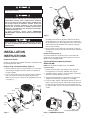
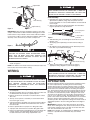
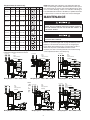
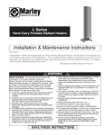
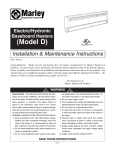
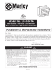
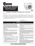
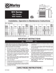
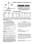
DH Series
Portable Industrial Unit
Blower Air Heaters
Installation, Operation & Maintenance Instructions
Table A- Model Specification and Cable / Plug Selection
MODEL
NUMBER
DH1021CKB
DH1583B
DH1521B
DH1523B
DH1543B
DH3043B
KW
10
15
15
15
15
30
VOLTS
240
208
240
240
480
480
BTUH
34,120
51,180
51,180
51,180
51,180
102,360
PH
1
3
1
3
3
3
AMPS
41.7
41.8
62.5
36.3
18.2
36.3
WIRING
DIAGRAM
NUMBER
WD4
WD5
WD2
WD1
WD3
WD6
SHIP
WT.
65 lbs
65 lbs
65 lbs
65 lbs
65 lbs
75 lbs
WIRE
SIZE
6/3
6/4
4/3
6/4
12/4
6/4
25 ft
CORD
SET
SCS10063*
SCS25064
SCS25043
SCS25064
SCS25124
SCS25064
OPTIONAL
Locking
Type
–
–
–
–
LPS25104
LPS25064
PLUGS
Non-Lock
Type
–
NPS1550
N6-50
NPS1550
–
–
* Cordset SCS10063 is 8 feet long with attached 50 amp, 250 volt, non-locking plug and is included with model DH1021CKB.
IMPORTANT INSTRUCTIONS
WARNING
!
When using electrical appliances, basic precautions should
always be followed to reduce the risk of fire, electric shock and
injury to persons, including the following:
8. This heater is not intended for use in bathrooms, laundry
areas and similar indoor locations. Never locate heater
where it may fall into a bathtub or other water container.
1. Read all instructions before using this heater.
9. Do not run cord under carpeting. Do not cover cord with
throw rugs, runners or the like. Arrange cord away from traffic area and where it will not be tripped over.
2. Verify the power suply voltage coming to the heater matches the ratings printed on the heater nameplate before energizing.
3. This heater is hot when in use. To avoid burns, do not let
bare skin touch hot surfaces. If provided, use handles when
moving this heater. Keep combustible materials, such as furniture, pillows, bedding, papers, clothes, and curtains at
least 3 feet (0.9 m) from the front of the heater and keep
them away from the sides and rear.
4. Extreme caution is necessary when any heater is used by or
near children or handicapped individuals and whenever the
heater is left operating and unattended.
5. Always disconnect heater when not in use.
6. Do not operate any heater with a damaged cord or plug or
after the heater malfunctions, has been dropped or damaged in any manner. Return heater to authorized service
facility for examination, electrical or mechanical adjustments, or repair.
7.
Do not use outdoors.
10. To disconnect heater, turn thermostat to fan only for 3 minutes, then turn to OFF, then remove plug from outlet.
11. Connect to properly grounded outlets only.
12. Do not insert or allow foreign objects to enter any ventilation
or exhaust opening as this may cause an electric shock, fire
or damage the heater.
13. To prevent a possible fire, do not block air intakes or exhaust
in any manner. Do not use on soft surfaces, like a bed,
where opening may become blocked.
14. A heater has hot and arcing or sparking parts inside.Do not
use it in areas where gasoline, paint or flammable liquids are
used or stored.
15. Use this heater only as described in this manual. Any other
use not recommended by the manufacturer may cause fire,
electric shock or injury to persons.
16. This heater is not intended for use with an extension cord.
17. Save these instructions.
SAVE THESE INSTRUCTIONS
ECR 39409
06/12
5200-11028-003
Handle
RISK OF FIRE. DO NOT USE AS A RESIDENTIAL OR
HOUSEHOLD HEATER.
Bolts
HAZARD OF FIRE OR DISCOLORATION OF TEMPERATURE
SENSITIVE FABRICS. DO NOT USE AS A RESIDENTIAL OR
HOUSEHOLD HEATER. KEEP COMBUSTIBLE MATERIAL
AND SUCH FABRICS AWAY FROM HEATER. DO NOT OPERATE HEATER WHERE FLAMMABLE VAPORS, GASES OR
LIQUIDS ARE PRESENT. HEATERS IN THE HEAT MODE
SHOULD NOT BE OPERATED IN ROOM TEMPERATURES
ABOVE 80°F. FAN MOTOR IS NOT DESIGNED TO OPERATE
IN AMBIENTS BELOW -40°F.
TO AVOID PERSONAL INJURY READ “IMPORTANT
INSTRUCTIONS” BEFORE INSTALLATION OR OPERATION
OF HEATER.
Figure 2
3 With the drum sitting on the large flange, align the leg
assembly to the bracket on the drum and insert the drum
knobs and spacers on either side of the drum, making sure
the tilt guide pins are in the tilt guide track. The access panel
and thermostat knob should be on the opposite side (top)
from the axle assembly
KEEP ELECTRICAL CORDS AND COMBUSTIBLE MATERIALS, SUCH AS DRAPES AND OTHER FURNISHINGS, AWAY
FROM HEATER.
4 Place a wheel on each end of the axel and put a cotter pin
through the axel holes to keep the wheels in place. Stand the
unit upright
INSTALLATION
INSTRUCTIONS
Handle Assembly (Figure 2)
To position handle, line up with the holes in the handle with
upper holes in the support legs and insert bolts to secure the
handle in the full upright position.
Assembly of Heater
Heaters are shipped unassembled and can be assembled easily
by following the steps below.
Optional Wall/Ceiling Mounting Bracket –
Model DHCWM
Support Legs and Axle Assembly (Figure 1)
NOTE: For installation of flexible cords, see WIRING
INSTRUCTIONS.
1 Remove the drum from the carton and sit it on a soft surface
with the larger flanged end down to allow for installation of
the leg assembly.
1. Remove the drum knobs and stop bolts, then remove the
housing from the cart (refer to exploded view, page 6).
2. Assemble hanger to heater as shown in Figure 4. Install the
drum knob and stop brackets as shown.
2 Place a washer onto each end of the axle and then slide the
legs over the axels until they are against the axle stops.
Make sure the legs are oriented so the tilt guide pins face in
(see Figure 1).
Leg
3. Secure mounting bracket to a surface that can support the
weight of the heater (refer to Table A for unit weight).
4. Loop secondary support cable through bracket as shown in
Figure . Secure ends with two cable clamps. Loop other end
of cable around any permanent structural member close to
fan (I-beam, rafter, joist, etc.) and secure ends with two cable
clamps.
Cushion
Support
Bracket
Spacer
Tilt Guide Pin
Drum
Knob
Cotter
Pin
Axle
Washer
Cushion
Support
Wall Mount Option
Figure 1
Figure 3 – DHCWM Mounting Bracket
2
Ceiling Mount Option
Support Cable
Bracket
ALL CONNECTIONS MUST BE TIGHT WITH ALL COPPER
WIRE STRANDS WITHIN THE CONNECTOR. A LOOSE OR
IMPROPERLY INSTALLED CONNECTOR CAN HEAT AND
COULD FAIL OR POSSIBLY CAUSE A FIRE HAZARD.
Hanger
Cord Assembly
1. Determine the gauge and number of conductors from the
Specifications (Table A) using amps and phase from the
heater nameplate. It is not recommended that cord exceed 50
feet in length.
2. Strip off outer jacket of cord and insulation from lead wires.
Figure 6 provides the strip dimensions.
Drum Knob (2)
Stop Bracket (2)
Figure 4
8”
1/2” Strip length for
power wire
IMPORTANT: Note the proper installation position of the cable
clamps as illustrated. To obtain maximum holding power, install
U-bolt section of clip on dead or short end of cable and saddle
on long end of cable as shown. Improper installation reduces the
efficiency of the connection by as much as 40 percent.
1” Strip length for
ground wire
Figure 6
3. Slide 90º fitting onto cord and tighten strain relief to secure
fitting to cord.
4. Select plug (sold separately) to match electrical rating of
cord.
5. On opposite end of cord prepare end as directed by instructions that are provided with the plug.
Figure 5
Wire Strap
FALLING HAZARD. WALL BRACKET MUST BE RELIABLY
ATTACHED TO BUILDING USING APPROPRIATE HARDWARE. TEST TO MAKE SURE WALL BRACKET CAN
SAFELY AND RELIABLY SUPPORT AT LEAST 100 LBS
BEFORE INSTALLING HEATER.
90º Fitting
Cable
Figure 7
5. Attach heater to bracket using the desired configuration
shown in Figure 3.
Strain Relief Screw (2)
6. Attach cord assembly to heater (Figure 7). Refer to
appropriate wiring diagram for your model (page 4).
NOTE: The bottom of the heater must be mounted at least 6 feet
from the floor and 2 feet from the ceiling.
WIRING
ALL CONNECTIONS MUST BE TIGHT WITH ALL COPPER
WIRE STRANDS WITHIN THE CONNECTOR. A LOOSE OR
IMPROPERLY INSTALLED CONNECTOR CAN HEAT AND
COULD FAIL OR POSSIBLY CAUSE A FIRE HAZARD.
ELECTRIC SHOCK HAZARD. DISCONNECT ALL POWER
BEFORE INSTALLING OR SERVICING HEATER. FAILURE TO
DO SO COULD RESULT IN PERSONAL INJURY OR PROPERTY DAMAGE. HEATER MUST BE EFFECTIVELY
GROUNDED IN ACCORDANCE WITH THE NATIONAL
ELECTRICAL CODE, NFPA 70.
OPERATION
DH Series Industrial Heaters are designed to gradually increase
the room temperature by circulating air across the heating
element. Best results occur when using the heater in confined
spaces with standard ceiling heights. Heaters include a bimetal
thermostat for the automatic control of the exiting air temperature. The thermostat knob controls the heating elements and fan
functions. The heater and fan are de-energized with the knob in
the extreme counterclockwise position. Turning the knob clockwise from the off position to the fan position will energize the fan
only, for use in summer cooling. The adjustment knob controls
power to the heater and fan when turned further in the clockwise
direction, with the highest temperature setting in the extreme
clockwise position. The temperature setting in the heater mode is
approximately 40°F in the low setting and 100°F at the highest
setting.
IMPORTANT: Cool down cycle. After operating in the heating
mode, when shutting down unit, always rotate control to the fan
only position and allow unit to cool down for at least three minutes. This will extend the life of the unit.
NOTE: Some models are equipped with an additional fan delay
feature. It is possible that the fan blade may start without
warning.
1. Use heater only at the voltage and frequency specified on
the nameplate.
2. All wiring should be done in accordance with local codes and
the National Electrical Code by a qualified person.
3. Branch circuit wire for connection to heater must be at least
90°C wire.
4. The top access panel is secured by 2 screws that must be
loosened to gain access.
5. A ground terminal is provided near the power terminal board.
The ground wire should be connected before other connections are made.
6. Refer to Specifications for proper size “SO” grade cable.
7. A proper strain relief must be used with “SO” grade cable.
8. Refer to the appropriate wiring diagram for your model in this
manual (page 4). The appropriate wiring diagram is also
located on the back of the wiring compartment cover.
3
Plug Specifications (for reference only)
Fits Cable Dia. Plug Type
Model
Description
NOTE: Should the unit activate the over temperature limit, the
cause of overheating should be determined before further operation. Check heater to ensure it has not been blocked in any manner, if so remove blockage. If there is no indication of blockage, it
is recommended the heater be checked by a qualified electrician
or repair service to ensure the heater has not been damaged.
Volts Amps Configuration NEMA # ANSI #
X
.385”-.780”
Locking
LPS25124 3 Pole, 4 Wire
250
G
L15-20 C73.85
G
L16-30 C73.88
G
L17-30 C73.89
Y
20
Z
X
Locking
.595”-1.150”
LPS25104 3 Pole, 4 Wire
480
30
Y
MAINTENANCE
Z
X
.595”-1.150”
Locking
LPS25084 3 Pole, 4 Wire
600
30
Y
Z
ELECTRIC SHOCK HAZARD. DISCONNECT HEATER FROM
POWER SUPPLY BEFORE SERVICING AND/OR INSPECTING THE HEATER; FAILURE TO DO SO MAY RESULT IN
ELECTRICAL SHOCK.
Y
.750”-1.125”
Locking
LPS25083 2 Pole, 4 Wire
600
50
—
—
—
—
6-50
C73.53
X
G
Y
Locking
.750”-1.125”
LPS25064 3 Pole, 4 Wire
600
50
X
Z
G
.625”-1.187”
Non Locking NPS25650 2 Pole, 3 Wire
250
50
.390”-.775”
Non Locking NPS1520 3 Pole, 4 Wire
250
20
ALLOW HEATER TO COOL
SERVICING OR CLEANING.
COMPLETELY
BEFORE
G
Z
15-20 C73.59
X
Replace or repair damaged cords or plugs immediately. Check
tightness of all electrical connections prior to energizing the
heater. Blow with compressed air or vacuum away any dirt or
debris that may have accumulated around the control
enclosure, fan motor or heating elements. The heater housing
can be wiped clean with a clean damp rag.
W
G
.750”-1.250”
Non Locking NPS1550 3 Pole, 4 Wire
250
X
50
15-50 C73.61
Z
W
DH Series Industrial Heaters are equipped with an over
temperature limit that will shut the heater
To Power Supply
L1
L2
L3
G
To Power Supply
240 V
15 KW
3 Phase Control Box
240 V
15 KW
1 Phase Control Box
To Power Supply
L1
L2
L3
G
G
Field Wiring
Field Wiring
L1
Wiring Diagram 1 - 240V / 15KW, 3 Phase
To Power Supply
L1
L2
G
240 V
10 KW
1 Phase Control Box
Field Wiring
Wiring Diagram 4 – 240V / 10KW, 1 Phase
down
in the
event
of
overheating.
Field Wiring
L2
Wiring Diagram 2 – 240V / 15KW, 1 Phase
Wiring Diagram 3 – 480V / 15KW, 3 Phase
To Power Supply
To Power Supply
L1
L2
L3
G
208 V
15 KW
3 Phase Control Box
480 V
15 KW
3 Phase Control Box
L1
L2
L3
G
480 V
30 KW
3 Phase Control Box
Optional
Field Wiring
Field Wiring
Wiring Diagram 5 – 208V / 15KW, 3 Phase
4
Wiring Diagram 6 – 480V / 30KW, 3 Phase
REPLACEMENT PARTS
13
6
12
5
7
4
14
10
3
11
16
1
2
15
9
8
REFERENCE
NUMBER
DESCRIPTION
PART NUMBER FOR MODELS:
DH1523B
DH1521B
DH1543B
QTY.
1
2
3
4
5
6
7
8
9
10
11
12
13
14
15
16
Not shown
Motor
Motor Capacitor
Inside Element
Outside Element
Contactor
Transformer
Fuse Block
Wheel
Axle Cap
Rear Guard
Front Guard
Tube Handle
Thermostat
Thermostat Knob
Drum Knob
Fan Blade
Fuse
390011002000
1432-0002-003
180211001002
180211001003
5018-0006-002
–
–
640611001000
140811002000
250411004000
250411005000
271011001000
5813-2059-000
330111018002
3301-11003-000
12100098001
–
390011002001
1432-0002-003
180211001002
180211001003
5018-0006-000
5814-0003-002
–
640611001000
140811002000
250411004000
250411005000
271011001000
5813-2059-000
330111018002
3301-11003-000
12100098001
–
1
1
3
3
1
1
2
2
2
1
1
1
1
1
2
1
4
Reference
Number
Description
Part Number for Models:
DH1021CKB
DH1583B
DH3043B
Qty.
1
2
3
4
5
6
7
8
9
10
11
12
13
14
15
16
Motor
Motor Capacitor
Inside Element (qty)
Outside Element (qty)
Contactor
Transformer
Fuse Block
Wheel
Axle Cap
Rear Guard
Front Guard
Tube Handle
Thermostat
Thermostat Knob
Drum Knob
Fan Blade
390011002000
1432-0002-003
180211001002 (2)
180211001003 (2)
5018-0006-002
–
–
640611001000
140811002000
250411004000
250411005000
271011001000
5813-2059-000
330111018002
3301-11003-000
12100098001
390011002000
1432-0002-003
180211001000 (3)
180211001001 (3)
5018-0006-002
–
–
640611001000
140811002000
250411004000
250411005000
271011001000
5813-2059-000
330111018002
3301-11003-000
12100098001
390011002001
1432-0002-003
180211001002 (6)
180211001003 (6)
5018-0006-000
5814-0003-002
–
640611001000
140811002000
250411004000
250411005000
271011001000
5813-2059-000
330111018002
3301-11003-000
12100098001
1
1
–
–
1
1
–
2
2
1
1
1
1
1
2
1
390011002000
1432-0002-003
180211001002
180211001003
50180006004
–
480030007
640611001000
140811002000
250411004000
250411005000
271011001000
5813-2059-000
330111018002
3301-11003-000
12100098001
2019-7008-077
5
LIMITED WARRANTY
All products manufactured by Marley Engineered Products are warranted against defects in workmanship and materials for one year from date of installation, except
heating elements which are warranted against defects in workmanship and materials for five years from date of installation. This warranty does not apply to damage from
accident, misuse, or alteration; nor where the connected voltage is more than 5% above the nameplate voltage; nor to equipment improperly installed or wired or
maintained in violation of the product’s installation instructions. All claims for warranty work must be accompanied by proof of the date of installation.
The customer shall be responsible for all costs incurred in the removal or reinstallation of products, including labor costs, and shipping costs incurred to return products to
Marley Engineered Products Service Center. Within the limitations of this warranty, inoperative units should be returned to the nearest Marley authorized service center
or the Marley Engineered Products Service Center, and we will repair or replace, at our option, at no charge to you with return freight paid by Marley. It is agreed that such
repair or replacement is the exclusive remedy available from Marley Engineered Products.
THE ABOVE WARRANTIES ARE IN LIEU OF ALL OTHER WARRANTIES EXPRESSED OR IMPLIED, AND ALL IMPLIED WARRANTIES OF MERCHANTABILITY AND
FITNESS FOR A PARTICULAR PURPOSE WHICH EXCEED THE AFORESAID EXPRESSED WARRANTIES ARE HEREBY DISCLAIMED AND EXCLUDED FROM THIS
AGREEMENT. MARLEY ENGINEERED PRODUCTS SHALL NOT BE LIABLE FOR CONSEQUENTIAL DAMAGES ARISING WITH RESPECT TO THE
PRODUCT, WHETHER BASED UPON NEGLIGENCE, TORT, STRICT LIABILITY, OR CONTRACT.
Some states do not allow the exclusion or limitation of incidental or consequential damages, so the above exclusion or limitation may not apply to you. This warranty gives
you specific legal rights, and you may also have other rights which vary from state to state.
For the address of your nearest authorized service center, contact Marley Engineered Products in Bennettsville, SC, at 1-800-642-4328. Merchandise returned to the factory must be accompanied by a return authorization and service identification tag, both available from Marley Engineered Products. When requesting return authorization,
include all catalog numbers shown on the products.
HOW TO OBTAIN WARRANTY SERVICE AND
WARRANTY PARTS PLUS GENERAL INFORMATION
1. Warranty Service or Parts
2. Purchase Replacement Parts
3. General Product Information
1-800-642-4328
1-800-654-3545
www.marleymep.com
Note: When obtaining service always have the following:
1. Model number of the product
2. Date of manufacture
3. Part number or description
470 Beauty Spot Rd. East
Bennettsville, SC 29512 USA