1
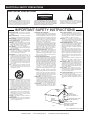
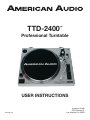
TTD-2400
™
Professional Turntable
USER INSTRUCTIONS
Revised 4/05
American Audio
4295 Charter St.
Los Angeles Ca. 90058
CONTENTS
ELECTRICAL CAUTIONS.......................................................................................................................3
ELECTRICAL SAFETY INSTRUCTIONS................................................................................................5
CHANGING OPERATING VOLTAGE...................................................................................................6
FEATURES....................................................................................................................................6
CUSTOMER SUPPORT .........................................................................................................................6
WARRANTY REGISTRATION.................................................................................................................6
QUICK START INSTRUCTIONS.............................................................................................................7
SET-UP INSTRUCTIONS........................................................................................................................8
HEADSHELL ASSEMBLY............................................................................................................9
COUNTERWEIGHT...................................................................................................................9
CONNECTIONS........................................................................................................................9
INSTALLATION.........................................................................................................................10
TONEARM BALANCING............................................................................................................10
ANTI-SKATE.............................................................................................................................11
DUST COVER............................................................................................................................11
FUNCTIONS AND CONTROLS............................................................................................................12
WARRANTY....................................................................................................................................15
SPECIFICATIONS............................................................................................................................16
CAUTION
Do not open risk of electric shock
CAUTION: TO REDUCE THE RISK OF ELECTRIC
SHOCK, DO NOT REMOVE THE COVER.
THERE ARE NO USER SERVICEABLE PARTS
INSIDE. REFER ALL SERVICE TO YOUR
AUTHORIZED AMERICAN AUDIO® DEALER.
The lightning flash with an arrow triangular
symbol is intended to alert the user to the
presence of non insulated “dangerous voltage” within the products enclosure, and
may be of sufficient magnitude to constitute
a risk of electric shock.
The exclamation point triangular symbol is
intended to alert the user to the presence
of important operating and maintenance
(servicing) instructions in the user manual
accompanying the amplifier.
©American
NOTE: This product satisfies FCC
regulations when shielded cables
and connectors are used to connect the unit to other equipment.
To prevent electromagnetic interference with electrical appliances
such as radios and televisions, use
shielded cables and connectors
for connections.
Audio® - www.americanaudio.us - TTD-2400™ Instruction Manual Page 3
ELECTRICAL SAFETY PRECAUTIONS
WARNING: TO PREVENT FIRE OR ELECTRIC
SHOCK HAZARD, DO NOT EXPOSE THIS
UNIT TO RAIN, LIQUIDS, OR MOISTURE
CAUTION: TO PREVENT ELECTRIC SHOCK
DO NOT USE THIS (POLARIZED) PLUG
WITH AN EXTENSION CORD, RECEPTACLE,
OR OTHER TYPE OF ELECTRICAL OUTLET
UNLESS THE WIDE BLADES CAN BE
CAREFULLY INSERTED INTO A MATCHING
WIDE SLOT.
ATTENTION: POUR PREVENIR LES CHOCS
ELECTRIQUES NE PAS UTILISER CETTE
FICHE POLARISEE AVEC UN PROLONGATEUR, UNE PRISE DE COURANT OU
UNE AUTRE SORTIE DE COURANT, SAUF
SI LES LAMES PEUVENT ETRE INSEREES A
FOND SANS EN LAISSER AUCUNE PARTIE A
DECOUVERT.
The serial and model number for this unit is
located on the rear panel. Please write down
the numbers here and retain for future reference.
Model No.______TTD-2400_______________
Serial No._____________________________
Purchase Notes:
Date of Purchase_______________________
Dealer Name__________________________
Dealer Address_________________________
_________________________________________
Dealer Phone_____________________________
©American
I. Heat - The turntable should be situated
away from heat sources such as radiators, heat
registers, stoves, or other appliances (including
amplifiers) that produce heat.
2. Do not let insecticides, benzene, or thinner
come in contact with the surface of the unit.
3. Never disassemble or modify your unit in
any way, doing so will void your manufactures
warranty.
4. Never plug this unit in to a dimmer pack
5. Do not attempt to operate this unit if it
becomes damaged in any way.
6. This unit is intended for indoor use only,
use of this product outdoors voids all warranties.
7. Always mount this unit in safe and stable
matter.
8. Disconnect from main power before making
any type of connection.
9. Cleaning - The turntable should be cleaned
only as recommended by the manufacturer.
Use a soft cloth to wipe down the outside of the
unit. For stubborn stains moisten a soft cloth
with class cleaner or other mild detergent to
wipe away any stains. Use a soft cloth to wipe
any residual cleaner. Never use volatile cleaners
such as benzene, solvent, or thinner to clean
your unit, these cleaners will damage the units
surface.
CAUTION:
1. Handle the power supply cord carefully. Do
not damage or deform; it may cause
electric shock or malfunction when used.
Hold plug attachment when removing from
wall outlet. Do not pull on the cord.
2. To avoid electric shock, do not open the
top cover when the unit is plugged in. If
problems occur with the unit, call American
Audio® customer support.
3. Do not place metal objects or spill liquid
inside or on the turntable. Electric shock
or malfunction may occur.
Audio® - www.americanaudio.us - TTD-2400™ Instruction Manual Page 4
ELECTRICAL SAFETY PRECAUTIONS
ELECTRICAL PRECAUTIONS
CAUTION
RISK OF ELECTRIC SHOCK
DO NOT OPEN
The lightning flash with arrowhead symbol, within an
equilateral triangle, is intended to alert the user to the
presence of uninsulated "dangerous voltage" within the
product's enclosure that may be of sufficient magnitude
to constitute a risk of electric shock to persons.
CAUTION: TO REDUCE THE RISK OF ELECTRIC
SHOCK, DO NOT REMOVE THE COVER (OR BACK).
THERE ARE NO USER SERVICEABLE PARTS
INSIDE REFER SERVICE TO YOUR AUTHORIZED
AMERICAN AUDIO® SERVICE TECHNICIAN.
The exclamation point within an equilateral triangle is
intended to alert the user to the presence of important
operating and maintenance (servicing) instructions in
the literature accompanying the appliance.
IMPORTANT SAFETY INSTRUCTIONS
READ INSTRUCTIONS — All the safety and operating
instructions should be read before the product is
operated.
RETAIN INSTRUCTIONS — The safety and operating
instructions should be retained for future reference.
HEED WARNINGS — All warnings on the product and
in the operating instructions should be adhered to.
FOLLOW INSTRUCTIONS — All operating and use
instructions should be followed.
CLEANING — The product should be cleaned only with
a polishing cloth or a soft dry cloth. Never clean with
furniture wax, benzine, insecticides or other volatile
liquids since they may corrode the cabinet.
ATTACHMENTS — Do not use attachments not
recommended by the product manufacturer as they
may cause hazards.
WATER AND MOISTURE — Do not use this product
near water — for example, near a bathtub, wash
bowl, kitchen sink, or laundry tub; in a wet basement;
or near a swimming pool; and the like.
ACCESSORIES — Do not place this product on an
unstable cart, stand, tripod, bracket, or table. The
product may fall, causing serious injury to a child or
adult, and serious damage to the product. Use only
with a cart, stand, tripod, bracket, or table
recommended by the manufacturer, or sold with
the product. Any mounting of the product should
follow the manufacturer’s instructions, and should
use a mounting accessory recommended by the
manufacturer.
CART — A product and cart combination should be
moved with care. Quick stops, excessive force, and
uneven surfaces may cause the product and cart
combination to overturn.
VENTILATION — Slots and openings in the cabinet are
provided for ventilation and to ensure reliable
operation of the product and to protect it from
overheating, and these openings must not be
blocked or covered. The openings should never be
blocked by placing the product on a bed, sofa, rug,
or other similar surface. This product should not be
placed in a built-in installation such as a bookcase or
rack unless proper ventilation is provided or the
manufacturer’s instructions have been adhered to.
POWER SOURCES —This product should be operated
only from the type of power source indicated on the
marking label. If you are not sure of the type of
power supply to your home, consult your product
dealer or local power company.
LOCATION – The appliance should be installed in a
stable location.
NONUSE PERIODS – The power cord of the appliance
should be unplugged from the outlet when left unused for a long period of time.
GROUNDING OR POLARIZATION
•
If this product is equipped with a polarized alternating
current line plug (a plug having one blade wider than
the other), it will fit into the outlet only one way. This
is a safety feature. If you are unable to insert the plug
fully into the outlet, try reversing the plug. If the plug
should still fail to fit, contact your electrician to
replace your obsolete outlet. Do not defeat the
safety purpose of the polarized plug.
•
If this product is equipped with a three-wire
grounding type plug, a plug having a third (grounding)
pin, it will only fit into a grounding type power outlet.
This is a safety feature. If you are unable to insert the
plug into the outlet, contact your electrician to
replace your obsolete outlet. Do not defeat the
safety purpose of the grounding type plug.
POWER-CORD PROTECTION - Power-supply cords
should be routed so that they are not likely to be
walked on or pinched by items placed upon or
against them, paying particular attention to cords at
plugs, convenience receptacles, and the point where
they exit from the product.
OUTDOOR ANTENNA GROUNDING — If an outside
antenna or cable system is connected to the product,
be sure the antenna or cable system is grounded so
as to provide some protection against voltage surges
and built-up static charges. Article 810 of the National
Electrical Code, ANSI/NFPA 70, provides information
with regard to proper grounding of the mast and
supporting structure, grounding of the lead-in wire
to an antenna discharge unit, size of grounding
conductors, location of antenna-discharge unit,
connection to grounding electrodes, and
requirements for the grounding electrode. See Figure
A.
LIGHTNING — For added protection for this product
during a lightning storm, or when it is left unattended
and unused for long periods of time, unplug it from
the wall outlet and disconnect the antenna or cable
system. This will prevent damage to the product
due to lightning and power-line surges.
POWER LINES — An outside antenna system should
not be located in the vicinity of overhead power lines
or other electric light or power circuits, or where it
can fall into such power lines or circuits. When
installing an outside antenna system, extreme care
should be taken to keep from touching such power
lines or circuits as contact with them might be fatal.
OVERLOADING — Do not overload wall outlets,
extension cords, or integral convenience receptacles
as this can result in a risk of fire or electric shock.
OBJECT AND LIQUID ENTRY - Never push objects of
any kind into this product through openings as they
may touch dangerous voltage points or short-out
parts that could result in a fire or electric shock.
Never spill liquid of any kind on the product.
SERVICING — Do not attempt to service this product
yourself as opening or removing covers may expose
you to dangerous voltage or other hazards. Refer all
servicing to qualified service personnel.
DAMAGE REQUIRING SERVICE - Unplug this product
from the wall outlet and refer servicing to qualified
service personnel under the following conditions:
•
When the power-supply cord or plug is damaged.
•
If liquid has been spilled, or objects have fallen into
the product.
•
If the product has been exposed to rain or water.
•
If the product does not operate normally by following
the operating instructions. Adjust only those controls
that are covered by the operating instructions as an
improper adjustment of other controls may result in
damage and will often require extensive work by a
qualified technician to restore the product to its
normal operation.
•
If the product has been dropped or damaged in any
way.
•
When the product exhibits a distinct change in
performance — this indicates a need for service.
REPLACEMENT PARTS -- W hen replacement parts
are required, be sure the service technician has used
replacement parts specified by the manufacturer or
have the same characteristics as the original part.
Unauthorized substitutions may result in fire, electric
shock, or other hazards.
SAFETY CHECK - Upon completion of any service or
repairs to this product, ask the service technician to
perform safety checks to determine that the product
is in proper operating condition.
WALL OR CEILING MOUNTING — The product should
not be mounted to a wall or ceiling.
HEAT — The product should be situated away from heat
sources such as radiators, heat registers, stoves, or
other products (including amplifiers) that produce
heat.
ANTENNA
LEAD IN
WIRE
GROUND
CLAMP
ANTENNA
DISCHARGE UNIT
(NEC SECTION 810-20)
ELECTRIC
SERVICE
EQUIPMENT
GROUNDING CONDUCTORS
(NEC SECTION 810-21)
GROUND CLAMPS
Fig. A
POWER SERVICE GROUNDING
ELECTRODE SYSTEM
(NEC ART 250, PART H)
NEC — NATIONAL ELECTRICAL CODE
©American
Audio® - www.americanaudio.us - TTD-2400™ Instruction Manual Page 5
PRODUCT INFORMATION
Please carefully read and understand the
instructions in this manual thoroughly before
attempting to operate this unit. These instructions contain important safety information
regarding the use and maintenance of this unit.
Take special care to follow all warning symbols
and labels both on the unit and printed in this
manual. Also, Please keep this manual with the
unit, for future reference.
LINE VOLTAGE SELECTION
• The desired voltage may be set with the
VOLTAGE SELECTOR switch, located
under the platter. (use a flat head screw
driver).
• Do not force the VOLTAGE SELECTOR
switch as this may cause damage
• If the VOLTAGE SELECTOR switch does
not move smoothly, please contact a qualified service technician.
4
I-SK AT
NT
3
E
1
2
0
Customer Support: American Audio® provides a toll free customer support line, to provide set up help and to answer any question
should you encounter problems during your
set up or initial operation. You may also visit us
on the web at www.americanaudio.us for any
comments or suggestions. For service related
issue please contact American Audio®. Service
Hours are Monday through Friday 9:00 a.m. to
5:00 p.m. Pacific Standard Time.
Voice:
(800) 322-6337
Fax: (323) 582-2610
E-mail:
[email protected]
To purchase parts online visit
http://parts.americandj.com
Warning! To prevent or reduce the risk of
electrical shock or fire, do not expose this unit
to rain or moisture.
Caution! There are no user serviceable parts
inside this unit. Do not attempt any repairs
yourself, doing so will void your manufactures
warranty. In the unlikely event your unit may
require service please contact customer support. Please do not return to your dealer without first contacting customer support.
A
110V-120V
220V-240V
119V
T T D - 2400 Direc t-Drive P rofes s iona l Turnta ble
230V
Features:
•
•
•
•
•
•
•
•
•
•
•
All Metal Tone Arm
Platter Start/Stop Button
2 Speeds (33 & 45 RPM)
0% Pitch Quartz Lock
Extra Stylus Holder
Adjustable Feet for Leveling
Adjustable Pitch Ranges +/- 10%
Anti-Skating Tone Arm Adjustment
Tone Arm Holder with Lock
Built-in 45 Adapter& Holder
User Selectable Operating Voltage
(115v~60Hz or 230v~50Hz)
©American
The shipping carton and packing materials are constructed of recyclable material,
please recycle when ever possible.
WARRANTY REGISTRATION
The TTD-2400™ carries a ONE year (365 days)
limited warranty. This warranty covers parts
and labor. Please fill out the enclosed warranty
card to validate your purchase and warranty. All
returned service items whether under warranty
or not, must be freight pre-paid and accompany a return authorization (R.A.) number. If
the unit is under warranty, you must provide a
copy of your proof of purchase invoice. Please
contact American Audio® customer support at
(800) 322-6337 for a R.A. number. All package
not displaying a R.A. number on the outside of
the package will be returned to the shipper.
Audio® - www.americanaudio.us - TTD-2400™ Instruction Manual Page 6
QUICK-START
Turntable Quick-Start:
1. Changing Platter Speed
Use the RPM selectors (10 & 11) to change the platter speeds. The 33-rpm (10) and 45-rpm (11) speed
selectors change the platter rotation respectively.
2. Starting and Stopping the Platter
Use the START/STOP BUTTON (6) to switch back and forth between platter rotation and pause
modes.
3. Pitch Control
1. The pitch adjustment is a fine adjustment to the platter's RPMs.
2. The pitch adjustment is variable and may be adjusted between -10% and +10% of the platter
selected speed.
3. The pitch is changed by sliding the Pitch Slider (12) in an up and down motion.
4. The STROBE INDICATORS (2) on the rim of the PLATTER (20) can be used to visual approximate the platter pitch. These indicators are lit by the STROBE INDICATOR PILOT LAMP (4) as
they pass by the POWER SWITCH (5). At different pitch levels each row of STROBE INDICATORS
(2) may appear stand still.
Note: The use of heavy fluorescent lighting directly above the turntable will defeat the STROBE
LAMP PILOT LAMP (4) affect indicator accuracy.
Product Service:
1. Clean the stylus periodically with a soft brush to prevent the accumulation of dust.
2. When sound becomes distorted or noisy, check the stylus. If the stylus is worn out, replace
it with a new one.
3. From time to time, the dust cover and turntable cabinet should be wiped down with a soft,
dry cloth.
4. Volatile materials should not be used, such as: alcohol, thinner, benzine etc. They may remove
the paint or damage the luster.
©American
Audio® - www.americanaudio.us - TTD-2400™ Instruction Manual Page 6
SET-UP
Some assembly required before you can begin to use your new TTD-2400. Please follow the
assembly instruction below before attempting to use you new turntable.
ASSEMBLY:
Before you begin assembly please be sure all parts and accessories have arrived intact. Please use
the check list below to identify and order parts and accessories.
NOTES:
•
•
•
•
Do not connect the AC power plug before assembly has been completed.
Before turning the power on, make sure once again all the connections and power voltage
settings are correct. Always turn off the power when connecting or disconnecting.
Read this manual carefully before using the unit. Be sure to store the manual in a safe place for
future reference.
Attach a stylus cartridge to the HEADSHELL (7) before assembling the turntable unit.
Headshell Assembly:
When installing a cartridge, refer to the operating instructions of that cartridge. During installation,
attach the stylus protector to guard the stylus tip from damage.
Connect the HEADSHELL (7) lead wires to the cartridge terminals. The terminals of cartridges and the
HEADSHELL (7) lead wires are color coded. Connect each lead wire to the cartridge terminals of the
same color.
White (L+) .............……………......
Blue (L-) ....……………................
Red (R+) ..…………....................
Green (R-) .......……………............
Left channel +
Left channel Right channel +
Right channel -
Turntable Assembly:
1. REMOVING FROM CARTON:
Carefully remove the main unit with the packing material intact from the box. Remove the packing
material once the unit has been removed from the shipping carton. Be sure to locate all the accessories located in the packing material.
2. 45 ADAPTER (1):
Locate and remove the 45-rpm adapter from the packing material and place it in the 45 adapter cut
out on the top of the main unit.
3. TURNTABLE PLATTER (20):
Remove the turntable platter from the packing material and gently insert the platter into the CENTER
SPINDLE (3) on the base of the turntable unit.
4. SLIPMAT:
Remove the black slipmat from the packaging and place it on the PLATTER (20).
©American
Audio® - www.americanaudio.us - TTD-2400™ Instruction Manual Page 7
SET-UP
5. HEADSHELL (7):
Insert the HEADSHELL (7) into the front end of the TONEARM ASSEMBLY (9). While holding
HEADSHELL (7) firmly into the front end of the tonearm assembly, turn the HEADSHELL LOCKING
NUT (8) counter-clockwise to firmly secure the HEADSHELL (7) to TONEARM ASSEMBLY (9).
HEADSHELL
TONEARM ASSEMBLY (9)
HEADSHELL LOCKING NUT (8)
6. COUNTERWEIGHT (16):
Locate and remove the tonearm COUNTERWEIGHT (16) from the packaging. Slide COUNTERWEIGHT
(16) onto the rear of the TONEARM ASSEMBLY (9). Turn it lightly and it will screw onto the rear shaft
of the tonearm.
TONEARM ASSEMBLY (9)
COUNTERWEIGHT (16)
Turntable Connections:
1. Connect the unit's stereo output leads to a receiver or mixer. The red phono terminal represents
the right output channel and the white terminal represents the left output channel.
2. The thin black wire with a spade connector is the ground lead. The ground lead must be connect
to the mixer (receiver) to avoid pops and clicks associated with magnetic pick-up system such as
turntables.
Output Leads
Mixer (Receiver)
L (White)
-----------------------------> L Channel
R (Red)
-----------------------------> R Channel
GND (Spade) ----------------------------> Ground
©American
Audio® - www.americanaudio.us - TTD-2400™ Instruction Manual Page 8
SET-UP
3. Connect the power core to matching outlet for your area. Only connect the power cord after the
all other connections have been made.
NOTE: Be sure to connect the ground terminals firmly to the Mixer or receiver.
AMERICAN AUDIO
Stereo phono lead
Phono ground lead
Phono ground lead
Stereo phono lead
4
I-SK AT
NT
3
1
0
0
2
A
1
2
I-SK AT
NT
3
E
4
E
A
T T D - 2400 Direc t-Drive P rofes s iona l Turnta ble
T T D - 2400 Direc t-Drive P rofes s iona l Turnta ble
Turntable Installation:
1. Do not place the unit in a location where it will be exposed to direct sunlight or near any type of
heating appliance.
2. Do not place the unit in a location where there is high humidity or a lot of dust.
3. Cartridge may pick up slight sound pressure or vibrations of near by speakers. For best results,
do not install this unit too close to speakers.
4. Install this unit on a horizontal surface that is stable and vibration free.
5. The rubber feet have been specially designed to isolate the unit from excess vibration. The feet
may also be used to stabilize the main body horizontally. Adjust the height of the unit by turning the
feet in a clockwise or counter-clockwise direction.
Tonearm Balance and Stylus Pressure:
Adjustment of horizontal zero balance and stylus pressure:
1. Remove the stylus protective cover, if so equipped. Never touch the stylus tip during the adjust
ment.
2. Lower the TONEARM LEVER (13).
3. Release the tonearm clamp and release the tonearm from the arm rest.
4. Set the ANTI-SKATE (15) adjustment to zero.
5. Rotate the COUNTERWEIGHT (16) in either direction until the TONEARM (9) is perfectly balanced
©American
Audio® - www.americanaudio.us - TTD-2400™ Instruction Manual Page 9
SET-UP
horizontally (floats freely).
6. Return the TONEARM (9) to the arm rest and lock it in place.
7. Hold the COUNTERWEIGHT (16) stationary with one hand and rotate only the stylus-pressure ring
to bring the number “0” of the ring into alignment with the center line on the tonearm rear shaft.
8. Rotate the COUNTERWEIGHT (16) clockwise until the scale value corresponding to the recommended stylus pressure.
Note: The recommended stylus pressure of the optional cartridge that may have been included with
your unit is 2 grams. For all other cartridge systems please refer to the manufactures specification
included with the cartridge.
Anti-Skate:
The anti-skate adjustment prevents the TONEARM ASSEMBLY (9) from skipping across the record
from the centrifugal force that is caused spinning rotation of the PLATTER (20). The ANTI-SKATING
(15) control knob should be set to the same value as the stylus pressure. For example if your
COUNTERWEIGHT (16) is set to 2.5 grams the ANTI-SKATE (15) value should also be set to 2.5.
©American
Audio® - www.americanaudio.us - TTD-2400™ Instruction Manual Page 10
CONTROLS AND FUNCTIONS
20
1918
17
1
16
I-SKAT
NT
3
4
0
2
1
E
2
15
14
3
13
12
4
5
6
TTD -2400Direct-Drive Professional Turntable
7 8 9
10 11
1. EP ADAPTER -
This adapter allows you to play standard 7” EP vinyl
records with large center holes. Place the adapter on
the CENTER SPINDLE (3) 7" records.
2. STROBE INDICATORS -
The PLATTER (20) has four rows of indicators. These
indicators are used to visually detail various stages of
pitch. The indicators are illuminated by the STROBE
INDICATOR PILOT LAMP (4). Each row may appear to
stand still at different pitch levels.
Note: The use of heavy fluorescent lighting directly
above the turntable will defeat the STROBE LAMP
PILOT LAMP (4) affect indicator accuracy.
3. CENTER SPINDLE -
This spindle holds the turntable PLATTER (20) and
records stable and centered.
4. STROBE INDICATOR PILOT LAMP -
This is lamp specially designed to pulse a beam of
light at the STROBE INDICATORS (2) on the turntable
PLATTER (20). This will give the illusion that indicators
are not spinning at certain speeds.
5. POWER SWITCH -
This is a rotary power switch. To turn main power on
turn the switch in a clockwise direction. To turn main
power off turn the switch in counter-clockwise direction.
©American
Audio® - www.americanaudio.us - TTD-2400™ Instruction Manual Page 11
CONTROLS AND FUNCTIONS
6. START/STOP BUTTON -
This over sized push button controls platter motion.
When the unit is turned on the platter will not automatically begin to spin. Pressing the button once will
engage the high torque motor and spin the platter,
pressing this again will stop the platter.
7. STYLUS HEADSHELL -
The included HEADSHELL (7) is used to connect your
stylus with the tone arm.
8. HEADSHELL LOCKING NUT -
After attaching the headshell to the tonearm, this
locking nut will securely hold the headshell to the
tonearm.
9. S-SHAPED TONE ARM -
The tonearm is the mechanism that holds the HEADSHELL (7) and stylus allowing it to glide across a
record.
10. 33-RPM SPEED SELECTOR BUTTON - Engaging this button will rotate the platter at 33 revolutions per a minute (RPMs). A function LED will glow
when this function is activated.
11. 45-RPM SPEED SELECTOR BUTTONS - Engaging this button will rotate the platter at 45 RPMs.
A function LED will glow when this function is activated.
12. PITCH ADJUST SLIDER -
This slider is used to adjust the playback pitch percentage (platter speed). Use this slider to match the
BPM’s of this unit to that of another music source.
13. TONEARM LEVER -
This lever is used to safely elevates the tone arm
above a record surface without endangering a records
surface.
14. TONEARM CLAMP AND REST -
Use this rest to safely hold the tonearm in position
during non use and transportation.
15. ANTI-SKATE CONTROL -
The anti-skate applies inward force to the tonearm
to prevent outward skipping across the record due
to the centrifugal force cause by platter rotation. The
antiskate value should be equally to that of the stylus
counterweight pressure (see counterweight 16).
16. COUNTERWEIGHT -
The counterweight adjustment applies the proper
downward pressure on the stylus.
17. EXTRA STYLUS HOLDER -
This cut out has been designed to safely store an
extra stylus headshell.
18. RCA OUTPUT JACKS -
These jacks are used to send a low voltage "phono"
level output signal to a mixers "phono" input jacks.
Turntables should only be connected to “Phono”
inputs on a mixer. The red colored RCA jack represents the right channel input and the white represents the left channel input.
©American
Audio® - www.americanaudio.us - TTD-2400™ Instruction Manual Page 12
CONTROLS AND FUNCTIONS
19. GROUND CONNECTOR -
This ground connection is designed to reduce the
humming and popping noises associated with magnetic phono cartridges. Be sure to connect the turntable ground lead to any available ground terminal on
the same mixer the input signal leads are connected
to.
20. PLATTER -
This platter connects directly to the center spindle (3).
The platter and center spindle (3) holds a vinyl record
perfectly center. The platter also spins the record at a
consistent speed.
©American
Audio® - www.americanaudio.us - TTD-2400™ Instruction Manual Page 13
WARRANTY
1-YEAR LIMITED WARRANTY
A. American Audio® hereby warrants, to the original purchaser, American Audio® products to be
free of manufacturing defects in material and workmanship for a period of 1 Year (365 days) from
the date of purchase. This warranty shall be valid only if the product is purchased within the United
States of America, including possessions and territories. It is the owner’s responsibility to establish
the date and place of purchase by acceptable evidence, at the time service is sought.
B. For warranty service, send the product only to the American Audio® factory. All shipping
charges must be pre-paid. If the requested repairs or service (including parts replacement) are
within the terms of this warranty, American Audio® will pay return shipping charges only to a designated point within the United States. If the entire instrument is sent, it must be shipped in its original package. No accessories should be shipped with the product. If any accessories are shipped
with the product, American Audio® shall have no liability whatsoever for loss of or damage to any
such accessories, nor for the safe return thereof.
C. This warranty is void if the serial number has been altered or removed; if the product is modified in any manner which American Audio® concludes, after inspection, affects the reliability of the
product; if the product has been repaired or serviced by anyone other than the American Audio®
factory unless prior written authorization was issued to purchaser by American Audio®; if the product is damaged because not properly maintained as set forth in the instruction manual.
D. This is not a service contract, and this warranty does not include maintenance, cleaning or periodic check-up. During the period specified above, American Audio® will replace defective parts at
its expense, and will absorb all expenses for warranty service and repair labor by reason of defects
in material or workmanship. The sole responsibility of American Audio® under this warranty shall be
limited to the repair of the product, or replacement thereof, including parts, at the sole discretion of
American Audio®. All products covered by this warranty were manufactured after January 1, 1990,
and bear identifying marks to that effect.
E. American Audio® reserves the right to make changes in design and/or improvements upon its
products without any obligation to include these changes in any products theretofore manufactured.
F. No warranty, whether expressed or implied, is given or made with respect to any accessory
supplied with products described above. Except to the extent prohibited by applicable law, all
implied warranties made by American Audio® in connection with this product, including warranties
of merchantability or fitness, are limited in duration to the warranty period set forth above. And no
warranties, whether expressed or implied, including warranties of merchantability or fitness, shall
apply to this product after said period has expired. The consumer’s and or Dealer’s sole remedy
shall be such repair or replacement as is expressly provided above; and under no circumstances
shall American Audio® be liable for any loss or damage, direct or consequential, arising out of the
use of, or inability to use, this product.
G. This warranty is the only written warranty applicable to American Audio® Products and supersedes all prior warranties and written descriptions of warranty terms and conditions heretofore
published.
©American
Audio® - www.americanaudio.us - TTD-2400™ Instruction Manual Page 14
SPECIFICATIONS
GENERAL
Model:
System:
Dimensions:
American Audio® TTD-2400 - Direct Drive Phono Turntable
2-Speed Direct Drive Phono Turntable Table
17.72” (W) x 13.7” (D) x 5.4" (H)
450 (W) x 350 (D) x 139 (H) mm
Place on flat surface or mount in flat case
22 Lbs. / 9.5 Kgs
AC 115v~60Hz/230v~50Hz
9W
Operational Temperature: 5 to 35˚C (41 to 95˚F)
Operational Humidity: 45 to 85% RH (non-condensation)
Storage Temperature: -10 to 60˚C (4 to 140˚F)
Instruction Manual,
Headshell,
45 RPM Adaptor
Installation:
Weight:
Power supply:
Power consumption:
Environmental conditions:
Accessories:
TURNTABLE SECTION
Type:
Motor:
Driving Method:
Turntable Platter:
Speeds:
Wow and Flutter:
S/N Ratio:
Pitch Controls:
Starting Torque:
Braking System:
Starting Time:
Braking Time:
Time for Speed Change:
2 Speed Fully Manual
8 Pole, 2 Phase, Brushless DC Motor
Direct Drive
330 mm dia. Aluminum Diecast
33-1/3 and 45-rpm
Less than 0.15% WRMS (JIS WTD) with 331/3rpm
More than 50dB (DIN-B)
+/- 10%
More than 1 kgf.cm
Electronic brake
Less than 1 sec.
Less than 1 sec.
Less than 1 sec. from 33 to 45 rpm.
Less than 1 sec. from 45 to 33 rpm.
6~10 mm
5 sec.
High of Cue (first track):
Descend of Cue:
TONEARM SECTION
Type:
Effective Arm Length:
Overhang:
Tracking Error Angle:
Tracking Force Adjustment Range:
Applicable Cartridge Weight:
Anti-skating Range:
Output:
Frequency Response:
Channel Separation:
Channel Balance:
Needle Pressure range:
SPECIFICATION
DESCRIPTIONS
Output Difference::
Output Level:
Speed (Speed Range) +/- 10%
Speed (Center Range)
Wow and Flutter
Channel separation
©American
Static balanced straight shaped tonearm with detachable headshell
220mm
10mm
Less than 3 degree
3-4g
6-10g
0-7g
1.5-3.6mV at 1KHz 5cm/sec
20Hz - 20KHz
More than 15 dB
Within 2.5dB at 1KHz
2.5g
UNIT
dB
mv
Hz
Hz
%
dB
NORMAL
2.3
1.7~3.5
2.7K ,3.3K
2995~3005
0.13
16
LIMIT
2.54
1.5~3.6
2710 ,3290
2990~3010
0.15
15
Audio® - www.americanaudio.us - TTD-2400™ Instruction Manual Page 15
©American Audio®
American DJ® Group of Companies World Headquarters:
4295 Charter Street Los Angeles, CA 90058 USA
Tel: 323-582-2650 Fax: 323-582-2610
Web: www.americanaudio.us E-mail: [email protected]