1
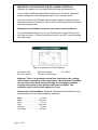
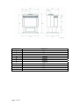
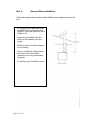
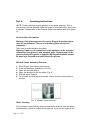
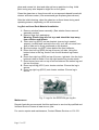
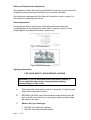
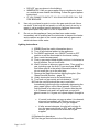
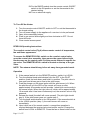
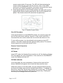
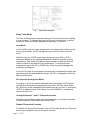
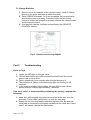
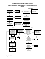
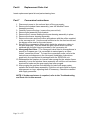
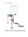
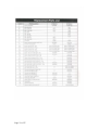
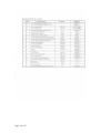
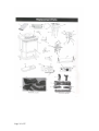
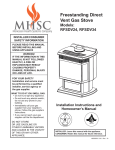
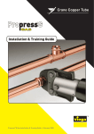
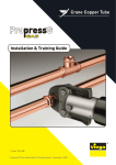
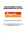
RAYPAK VERMONT RFSDV34
FREESTANDING GAS LOG FIRE
Installation and Operating Instructions
For Models RFSDV34RFNAU (Natural Gas) &
RFSDV34RFPAU (Propane)
Page 1 of 27
CONTENTS
Part 1:
For Your Safety
Part 2:
Installation Instructions
•
•
•
•
•
•
•
•
Part 3:
General Venting Information
•
•
•
•
Part 4:
Part 6:
Termination Clearances
General Information for Assembling Vent Pipes
Vertical Through Roof Applications
Install Vertical Venting
Operating Instructions
•
•
•
•
•
•
•
•
•
Part 5:
Start Up Recommendations
Locating The Fireplace
Clearance to Combustibles
Fireplace Dimensions
Gas Specifications
Gas Inlet and Manifold Pressures
Preparation
Gas Line Installation
General Glass Information
Window Frame Assembly Removal
Glass Cleaning
Log Set and Lava Rock Installation
Maintenance
Flame and Temperature Adjustment
Flame Appearance
Remote Control Options
RFSDV34 Lighting Instructions
Troubleshooting
• Troubleshooting the Gas Control System
Replacement Parts List
• Replacement Parts – drawing and list
Page 2 of 27
Part 7:
Conversion
• Gas Type Conversion Instruction
Part 8:
Wiring Diagram
• Wiring Diagram
Part 9:
Page 3 of 27
Warranty
Part 1:
For Your Safety
For your safety do not operate this appliance before reading this
instruction book.
Warning: Improper installation, adjustment, alteration, service or
maintenance can cause injury or property damage. For assistance
or additional information consult with Raypak Australia, your
Raypak distributor, qualified installer or accredited Rheem
Australia Service Agency.
WHAT TO DO IF YOU SMELL GAS?
DO NOT try to light any gas appliance.
DO NOT touch any electrical switch.
Turn off gas supply at the meter.
Immediately call Rheem Service, your gas supplier or licensed gasfitter.
Note: Some gases are heavier than air and it maybe necessary to check for gas
leaks at floor level.
CAUTION!
DO NOT operate this appliance before reading this instruction booklet.
DO NOT place articles or objects on or against the appliance.
DO NOT store chemicals or flammable materials in the same room as this
appliance.
DO NOT store chemicals or flammable materials on, or spray aerosols near this
appliance.
DO NOT operate with panels, covers or guards removed from the appliance.
Page 4 of 27
Part 2:
Installation Instructions
This gas fireplace must be installed by a qualified installer in accordance with
AS5601 and all relevant local building codes.
For safe installation and operation please note the following:
1. This fireplace gives off high temperatures and should be located out of
high traffic areas and away from furniture and draperies.
2. Children and adults should be alerted to the hazards of fireplace high
surface temperatures and should stay away to avoid burns or ignition
of clothing.
3. CAUTION: Due to high glass surface temperatures children
should be carefully supervised when in the same room as the
appliance.
4. Under no circumstances should this fireplace be modified or altered.
Parts removed for servicing should be replaced prior to operating this
fireplace again.
5. Installation and any repairs to this fireplace must be performed by a
qualified installer, service agency or service person. A qualified service
person should be contacted to inspect the fireplace annually.
6. Control compartments, burners and air passages in this fireplace
should be kept clean and free of dust and lint. Make sure that the gas
valve and pilot light are turned off before you attempt to clean this
appliance.
7. The flueing system should be checked once a year and cleaned if
required.
8. Keep the area surrounding this appliance clear of combustible
materials, gasoline and other flammable vapour and liquids. This
heater should not be used as a drying rack for clothing.
9. Under no circumstances should any solid fuels (wood, paper, coal or
cardboard etc.) be used in this appliance.
10. The flow of combustion and ventilation air must not be obstructed in
any way.
11. When this appliance is installed directly on carpeting, vinyl tile, linoleum
or any combustible material other than wood, this fireplace must be
installed on a metal or panel extending the full width and depth of the
appliance.
12. This appliance requires adequate ventilation and combustion air to
operate properly – refer to AS5601 ventilation and combustion air
requirements.
13. This appliance must not be connected to a chimney flue serving a
separate solid fuel burning fireplace.
14. When the fireplace is not in use it is recommended that the gas control
valve be left in the OFF position.
Page 5 of 27
IMPORTANT: PLEASE READ THE FOLLOWING CAREFULLY
Remove any plastic from trim parts before turning the appliance on.
It is normal for fireplaces fabricated of steel to give off some expansion
and/or contraction noises during the start up or cool down cycle.
It is not unusual for the Raypak Vermont gas fireplace to produce some
odour the first time it is burned. This is due to residual oils used during the
manufacturing process.
Please open all windows to ensure your room is well ventilated.
It is recommended that you burn your fireplace for at least 10 hours the
first time you use it. Please turn the fan switch in the OFF position during
this initial firing.
Fig. 1 Locating Your Gas Fireplace
A) Flat on wall*
D) Cross corner
B) Room divider*
E) Flat on wall corner
C) Island
Warning: There is a minimum vertical rise required for the venting,
which varies depending on the application. The maximum horizontal
run also has restrictions. Before starting the installation read the
venting instructions in this booklet and refer to AS5601. The
minimum vertical rise for this appliance is 3m.
Clearance to Combustibles: Adequate clearances as listed below must
be maintained for servicing and proper operation.
Back…………………………0 mm
Side………………………305 mm
Floor………………………...0 mm
Top……………………….915 mm
Corner………………………0 mm
Flue Pipe………………….25 mm
Page 6 of 27
DIMENSION
A
B
C
D
E
F
G
H
I
J
K
Page 7 of 27
RFSDV34
667mm
800mm
492mm
762mm
254mm
394mm
114mm
667mm
333mm
495mm
162mm
Gas Specifications
Model
Gas Type
Gas Control
RFSDV34RFN
RFSDV34RFP
Natural
Propane
Radio Freq.
Radio Freq.
Min. MJ/h
Input
22
24
Max. MJ/h
Input
32
32
Gas Inlet and Burner Pressures
Inlet Minimum
Inlet Maximum
Burner Pressure
Natural Gas
1.1 kPa
3.50 kPa
0.87 kPa
ULPG
2.75 kPa
3.50 kPa
2.50 kPa
Preparation
Warning: The use of wall paper adjacent to this fireplace is not
recommended, as the heat produced by this appliance may adversely
affect the binders in the adhesive used to apply the wall paper.
Before beginning, remove the window frame assembly from the heater and
ensure that there is not hidden damage to the heater.
Take some time to plan the fitting line, flue and electrical supply.
On completion of the installation ensure that the appliance is
commissioned and tested.
Fitting Line Installation
Warning: When purging the fitting line, the front glass must be
removed.
Note: For pipe sizing requirements refer to Australian Standard AS5601
Gas Installations.
If gas fitting line has been previously completed, check that the gas fitting
line is of adequate size. Refer to Australian Standard AS5601 Gas
Installations.
The gas fitting line can be brought in through the rear or the bottom of the
appliance. Openings are provided on the bottom behind the valve to allow
for the gas fitting line installation and testing of any gas connection. It
preferable to bring the fitting line in from the rear right side of the valve as
this allows fan installation or removal without the need to disconnect the
gas fitting line.
Page 8 of 27
Note: When making the gas connection to the appliance inlet fitting, hold
the 10mm 3/8” BSP fitting with a spanner when tightening the gas inlet
pipe compression nut.
For Propane installations an approved gas regulator must be fitted in
accordance with AS5601.
Ensure copper tube meets the requirements of Australian Standard
AS1432 Type B.
Note: Heater must be tested for correct operation by the installer after
installation is complete.
Page 9 of 27
Part 3:
General Flue Installation
Underside of gas cowl must be at least 500mm above highest point of the
roof.
This appliance is approved for an
installation with a maximum flue
height of 12m and a minimum flue
height of 3m.
Suspend a plumbline from the
ceiling to the centre of the flue
spigot.
Mark the centre of the flue spigot
on the ceiling.
Prior to cutting the ceiling ensure
that there is at lease 25mm
clearance from any combustible
materials.
Fit ceiling ring, flue and flue cover.
Page 10 of 27
Part 4:
Operating Instructions
NOTE: Carbon deposits maybe present on the glass and logs. This is
normal and must be cleaned when the heater is serviced or the glass door
is cleaned. Please refer to the General Glass Information section on page
15.
General Glass Information
Warning: Only glass approved for use by Raypak Australia may be
used for replacement. The use of substitute glass will void all
warranties.
Take care to avoid breaking the glass.
Warning: Under no circumstances is this appliance to be operated
without the front glass or with a broken glass. Replacement of the
glass including the gasket as supplied by Raypak Australia should
be done by a licensed and qualified service person.
Window Frame Assembly Removal
1.
2.
3.
4.
5.
6.
Shut off gas. (see lighting instructions)
If the unit has been operating, let it cool.
Open the two side doors.
Open the clamps on the two sides (Fig. 2)
Pull the frame forward.
To re-install window frame assembly, follow the above procedure in
reverse
Fig. 2 Window frame removal
Glass Cleaning
It is necessary to periodically clean condensation and film from the glass.
Condensation, which is normal during start up, forms on the inside of the
Page 11 of 27
glass and causes lint, dust and other air-borne particles to cling. Initial
paint curing may also deposit a slight film on the glass.
Clean the glass two or three times with a non-ammonia based household
cleaner and warm water. (We recommend gas fireplace glass cleaner.)
After the initial cleaning, clean the glass two or three times during each
operating season, depending on the environment.
Log Set and Lava Rock Material Installation
1. Remove window frame assembly. (See window frame removal
assembly section)
2. Remove logs from packaging.
Warning: Plastic bags are not toys and should be kept away
from children and infants.
3. Place rear log (KR10) on rear bracket (ensure log is seated.
properly, levelled and centred to the unit), so it will not move from
side to side and is firmly positioned on the bracket.
4. Slip front ember log (KR7) down behind the front deflector.
5. Place front left log (KR8) on top of burner, left side. Using the
bottom holes in the log, locate it into the left bracket log locator
studs.
6. Place front right log (KR9) on top of burner, right side. Use the log’s
bottoms holes to locate it into the right bracket log locator studs.
7. Place burner lava rock on top of burner between the ember log and
the two front logs.
8. Place top left log (KR11) onto locator notches. Ensure the log is
secure.
9. Place top right log (KR12) onto locator notches. Ensure log is
secure.
Fig. 3 Logs for the RFSDV34 gas log fire
Maintenance
Raypak Australia recommends that this appliance is serviced by qualified and
licensed Service Person at least once a year.
For service repairs and maintenance, Contact Rheem Service on 131 031.
Page 12 of 27
Flame and Temperature Adjustment
The appliance is fitted with the Honeywell Radio Frequency control valve and
all adjustments are performed with the use of a remote controller.
See instructions packaged with the Remote Controller or refer to page 16 in
this manual for operating instructions.
Flame Appearance
Periodically perform a visual check of the pilot and burner flames by
comparing them to the illustrations below (refer to figures 4 and 5). If any
flames appear to be abnormal, place a service call.
Fig 4. DVT pilot flame
Fig.5 RFSDV34 flames
Lighting Instructions
FOR YOUR SAFETY, READ BEFORE LIGHTING
WARNING: If you do not follow these instructions exactly, a
fire or explosion may result, causing property damage,
personal injury or loss of life.
A.
This heater has a pilot which must be lit manually. To light the pilot,
follow these instructions exactly.
B.
BEFORE LIGHTING, smell all around the heater area for gas. Be
sure to smell next to the floor as some gas is heavier than air and
will settle on the floor.
C.
What to do if you smell gas:
•
•
Page 13 of 27
DO NOT try to light any fireplace.
DO NOT touch any electrical switch.
•
•
•
DO NOT use any phone in the building.
IMMEDIATELY call you gas supplier from a neighbour’s phone
or a mobile phone outside the building. Follow the gas suppliers
instructions.
IF YOU CANNOT CONTACT YOU GAS SUPPLIER CALL THE
FIRE BRIGADE.
D.
Use only your hand to push in or turn the gas control knob. Never
use tools. If the knob will not push in or turn by hand, do not try to
repair it; call a qualified service technician. Applying force or any
attempted repair may result in a fire or explosion.
E.
Do not use this appliance if any part has been under water.
Immediately call a qualified service technician to inspect the heater
and to replace any part of the control system and any gas control
which has been under water.
Lighting Instructions
1. STOP!! Read the safety information above.
2. Turn off all electrical power to the appliance.
3. For RN/RP appliances, turn ON/OFF switch to OFF
position or set the thermostat to the lowest setting.
4. Open control access panel.
5. Push in gas control knob slightly and turn it clockwise to
the off position. Do not force knob.
6. Wait 5 minutes to allow any gas to clear. Then smell for
gas, including near the floor. If you smell gas, STOP
and follow step B in the safety information above. If you
do not smell gas, go to the next step.
7. Remove the glass door before lighting the pilot. (See
Glass Removal Section – page 10)
8. Visibly locate pilot next to the main burner.
9. Turn knob on gas control anti-clockwise to “PILOT”
10. Push the control knob all the way in and hold.
Immediately light the pilot by repeatedly depressing the
piezo spark ignitor until a flame appears. Continue to
hold the knob in for about one (1) minute after the pilot
is lit. Release knob and it will pop back up and pilot
should remain lit. If it goes out repeat steps 5 through to
8.
•
•
If control knob does not pop up when it is released,
stop and immediately call Rheem service, your
local service technician or your gas supplier.
If after several attempts, the pilot will not stay lit,
turn the gas control knob to OFF and call Rheem
service, your local service technician or gas
supplier.
11. Replace the glass door.
12. Turn the gas control knob to the ON position.
Page 14 of 27
13. For the RN/RP models turn the remote control ON/OFF
switch to the ON position or set the thermostat to the
desired setting.
14. Turn on electrical supply.
To Turn Off the Heater
1. Turn the remote control ON/OFF switch to OFF or set the thermostat to
the lowest setting.
2. Turn off power supply to the appliance if a service is to be performed.
3. Open louvre assembly bottom.
4. Push in gas control knob slightly and turn clockwise to OFF. Do not
force this knob.
5. Close control access panel.
RFSDV34 Operating Instructions
The comfort control valve (Fig 6) allows remote control of temperature,
fan and flame appearance.
To access the REMOTE/LOCAL switch on the comfort control valve;
open the control door assembly, then remove the upper left and right
hand screws on the control panel. Pull the panels forward to expose the
gas valve. The REMOTE/LOCAL switch is located on the top of the gas
valve.
NOTE: The antenna should hang in free air away from grounded metal.
Operation
1. If the manual switch is in the REMOTE position, switch it to LOCAL.
2. Turn the pilotstat knob anticlockwise from the OFF to the PILOT
position, push the knob down and hold it in position. The pilot valve is
now open and allows gas to flow to the pilot burner.
3. Push the plunger on the piezo ignitor until the pilot burner is lit. When
the pilot burner is lit the LED on the control will come on after
approximately 40 seconds and will provide 1 short blink continuously in
the normal mode. When the light turns off, which will be approximately
10 seconds after it has been continuously red, the receiver valve is fully
powered.
4. Release the knob (the shaft will move upward). The pilot light should
stay lit. If the pilot burner goes out, repeat step 2.
5. Turn the knob anticlockwise to the ON position. If the manual switch is
in the LOCAL position (step 1), the main burner will come on
immediately.
6. Upon initial use of the remote control, a recognition operation is
required between the receiver/valve and remote control. Change the
switch from LOCAL to REMOTE . Press the fan or flame button on the
Page 15 of 27
remote control within 30 seconds. The LED will blink indicating the
remote control will now work with the receiver valve. If the switch
continues in the REMOTE position, the remote control will now control
the main valve, flame modulation level and fan control.
7. If the manual switch is in the LOCAL position, the valve will be at the
highest fixed pressure setting and the fan will be at the highest fixed
speed. The remote control will control the fan speed only.
Fig. 6 Comfort Control Valve
Shut Off Procedure
If the manual switch is in the REMOTE position, the remote control can
shut off the main burner and fan. However, if the control is still ON a
command from the remote control can turn on the main burner or fan.
To shut off the system, turn the pilotstat knob clockwise to the OFF
position. This action closes the main gas and safety valves. The remote
control cannot turn on the main burner or fan.
Remote Control Operation
Refer to Fig 7
OFF Mode
In the OFF mode, the fireplace flame and fan are off, the display will show
OFF and display the room temperature. If the receiver is in the REMOTE
mode, the fireplace will shut off.
ON Mode (Manual)
In the ON mode, the room temperature, flame and fan levels will be
shown. MANUAL will appear next to both the flame and fan icons.
When the control is in the ON mode, you can change the flame and fan
levels and the delay timer with the Up and Down buttons. To change the
flame level, press the Flame button followed by an arrow key. To change
the fan level, press the Fan key followed by an arrow key. Pushing the
arrow key once changes the level by one unit
Page 16 of 27
Fig.7 Transmitter diagram
Delay Timer Mode
The shut off delay timer maximum setting is 2 hours and minimum setting
is zero minutes. To change the timer level, press the timer key, then the
arrow key. Each key press changes the setting by 10 minutes.
Auto Mode
In the AUTO mode, the room temperature, set temperature, flame and fan
levels will be shown. AUTO will appear next to both the flame and fan
icons.
With the control in AUTO mode, the main burner turns ON or OFF or
modulates based on the heating differential needed to maintain the set
temperature. The flame level adjusts automatically to optimize the heat
output required to maintain the set temperature. To change the set
temperature, press the UP or DOWN key. Each key press changes the
setting by one degree.
In the AUTO mode, the fan speed increases with increased fan height and
decreases with the decreased fan height. “AUTO” is displayed next to the
flame and fan icons.
Fan Override During Auto Mode
If a higher or lower fan speed is desired when operating in AUTO mode,
override the fan speed by pressing the fan button, then the Up or Down
key. Each key press changes the fan speed level by one unit. In this mode
“AUTO” is displayed next to the flame icon and “MANUAL” is displayed
next to the Fan icon.
Change Between F° and C° Temperature Units
Press the Up and Down arrow keys simultaneously for at least 3 seconds
to switch between Fahrenheit and Celsius units.
Disable Thermostat Function
To disable the thermostat function in the AUTO mode, press the Timer and
Down keys simultaneously for at least 3 seconds.
Page 17 of 27
To Change Batteries
1. Remove cover on backside of the remote control. Install 3 AAA as
shown on the cover and then re-attach the cover.
2. Once OPERATION steps 1 to 3 are completed, the receiver/valve
and remote control are ready. Press any button on the remote
control to initiate the recognition process between the receiver/valve
and the remote control.
3. You may now use the functions as described in the REMOTE
CONTROL section.
Fig 8. Comfort control wiring diagram
Part 5
Troubleshooting
Refer to Fig 6
1. Locate the LED light on the gas valve.
2. LED will blink after every valid command received from the remote
control; this is not an error.
3. Failure codes may occur anytime after the pilot burner is lit.
4. The sequence is: failure code followed by light not blinking for 30
seconds.
5. In the event of multiple failure codes, the next failure code follows
previous failure code by approximately 3 seconds.
If an error code 3 is observed while performing the testing, complete the
following:
1. Make sure all the spade connectors are pushed all the way onto the
terminals. If error code 3 still shows, go onto the next step.
2. Switch the two front thermopile leads with the back two. Be sure the
white lead is connected to the spade marked with the white dot. If error
code 3 still shows, replace the thermopiles.
Page 18 of 27
If an error code 8 is observed while performing the testing, complete the
following:
1. Confirm that the gas valve is not in the REMOTE mode.
• If the valve is producing error code 8 while in the REMOTE
mode, the valve is defective and should be replaced.
• If the valve is producing error code 8 while in the LOCAL mode,
go to the next step.
2. Slide the REMOTE/LOCAL switch to REMOTE and program the
remote control as per item 6 page 13. The error code will clear itself after
approximately 1.5 minutes and return to normal operation.
Page 19 of 27
Troubleshooting the Gas Control System
Comfort Valve System Control Sequence of Operation with Remote
Control
Local Path
Set manual switch
to local or remote
Five minute
wait period
Light pilot burner
Yes
Did the LED stop
blinking?
Review LED
failure analysis
Release pilotstat
knob
Turn pilotstat knob to
PILOT to turn off
main burner
Turn pilotstat knob to
OFF to turn valve
completely off.
Cycle switch once and
leave in remote. Press
any key on the Remote
Control for recognition
operation.
Turn pilotstat
knob from PILOT
to ON
On Path
If the manual switch
is set to remote,
press the mode
button to display ON.
Does the remote
control the main
burner and fan?
Does remote
control change
levels of flame
height, fan speed?
Yes
Set levels of flame
height and fan to
“0” to shut off
main burner and
fan
Turn pilotstat knob
to OFF to turn
valve completely
off
Choose Manual or
Remote path. Set
switch to manual or
remote.
Auto Path
Move switch from
manual to remote.
Press any key on
remote control
Yes
Page 20 of 27
Move switch from
manual to remote.
Press any key on the
remote control.
Move switch back to
If manual switch is
set to LOCAL, did
main burner light
and fan turn on?
No
If the manual switch
is set to remote,
press the mode
button to display
AUTO. Does the
remote control
display the room and
temperature
settings?
Move switch from
local to remote.
Press any key on
remote control
within 30 seconds
If the setting is
above room
temperature on
the remote control
does the main
valve and fan turn
on?
No
If the setting is
below room
temperature on
the remote
control, does the
main valve and
fan turn off?
No
Turn pilotstat knob
to OFF to turn
valve completely
off.
Part 6
Replacement Parts List
Insert replacement parts list and parts drawing here.
Part 7
Conversion Instructions
1. Disconnect power to the unit and shut off the gas supply.
2. Remove the window frame assembly. (see the Window Frame
Assembly section)
3. Carefully remove the logs. (ensure they are not hot)
4. Remove pilot assembly from bracket.
5. Remove the 2 screws holding the burner housing assembly in place.
6. Remove the burner housing assembly.
7. Remove the main and front orifice and replace with the orifice supplied
in the conversion kit. Use the small orifice size for the front burner and
the bigger orifice size for the main burner.
8. Remove the compression fitting which holds the aluminium tubing in
the pilot assembly. This will reveal the pilot injector which must be
replaced with the pilot injector provided in the conversion kit.
9. Honeywell Gas Valve -: The Honeywell valve fitted to this appliance is
preset for Propane gas. It is convertible to natural gas by a colour
coded “conversion screw”. To insert the conversion screw, refer to the
instructions and diagrams in the Honeywell Installation Instructions
supplied in the conversion kit packaged with the RFSDV34 unit.
10. Reassemble the fireplace in reverse order except for the window frame
assembly. Leave the window frame assembly off until the unit has been
checked for leaks and the gas supply has been purged.
11. After purging the gas line and checking for leaks with soapy water,
replace the window frame assembly. Light the unit and check for frame
impingement on logs, adjusting them if necessary. Check the manifold
and supply pressures.
NOTE: If further assistance is required, refer to the Troubleshooting
and Parts List in this manual.
Page 21 of 27
Wiring Diagram
A
N
Part 8
240V AC
Terminal Block
Fuse - 3 Amp
Transformer
240V AC - 110V AC
2A (50VA)
Speed Control
240V AC 50 Hz
Main Heater Supply
High Limit
Fan
RFSDV34 GAS LOG FIRE WIRING DIAGRAM
Page 22 of 27
Page 23 of 27
Page 24 of 27
Page 25 of 27
Part 9
Warranty
RAYPAK RFSDV34RFN & RFSDV34RFP
FREESTANDING GAS LOG FIRE WARANTY
- AUSTRALIA ONLY –
Rheem Australia * will:
a) Repair or, if necessary replace any Raypak RFSDV34 Freestanding Gas Log Fire, or
b) Replace any component (or, if necessary, arrange the installation of a Raypak Gas
Log Fire, which falls within the Warranty Periods specified below, in accordance with
and subject table, conditions and exclusions.
Installation
Models
From date of installation
Freestanding
RFSDV34RFN &
Gas Log Fire
RFSDV34RFP
Period
Warranty
Year 1
Labour
Freestanding
Gas Log Fire
RFSDV34RFN &
RFSDV34RFP
Years 2
Parts
Fan and other components
Freestanding
Gas Log Fire
RFSDV34RFN &
RFSDV34RFP
Years 10
Parts
This warranty covers the appliance
heat exchanger for 10 years pro-rata
with a 1 year labour warranty.
Notes:
* Rheem Australia Pty Ltd provides warranty service and spare parts on behalf of
Raypak Australia Pty. Ltd.
** Refer to item 5 of warranty conditions.
Rheem reserves the right to transfer fully functional components from the defective gas
log fire to the replacement appliance if required.
In addition to this warranty, the Trade Practices Act 1974 and similar laws in each state
and territory provide the owner under certain circumstances with certain minimum
statutory rights in relation to your Raypak gas log fire. This warranty must be read subject
to that legislation and nothing in this warranty has the effect of excluding, restricting or
modifying those rights.
Rheem Australia Pty Ltd
A.B.N 21 098 823 511
Raypak Australia Pty Ltd
A.B.N 65 078 743 414
Page 26 of 27
FOR SERVICE TELEPHONE
131 031 AUSTRALIA
or refer to your local yellow pages
RAYPAK MAJESTIC RFSDV34RFNAU AND
RFSD34RFPAU WARRANTY
- AUSTRALIA ONLY –
WARRANTY CONDITIONS
1.
2.
3.
4.
5.
6.
This warranty is applicable only to the RFSDV34RFN and the RFSDV34RFP gas
log fires manufactured from August 2005
The gas log fire must be installed in accordance with the Raypak installation
instructions, supplied with the appliance and in accordance with all relevant
statutory and local requirements of the State in which the appliance is installed.
This gas log fire must be correctly commissioned by a licensed and authorised
person and the installation certified by the relevant Gas Authority of the State in
which the appliance is installed.
Where a failed component or appliance is replaced under warranty, the balance
of the original warranty period will remain effective. The replaced part of
appliance does not carry a new warranty.
Where the gas log fire is installed outside the boundaries of the metropolitan area
as defined by Rheem or further than 25 km from a regional Rheem branch office,
or an accredited service agent, the cost of transport, insurance and travelling
costs between the nearest Rheem accredited Service Agent’s premises and the
installed site shall be owner’s responsibility.
The warranty only applies to the gas log fire and original or genuine (company)
component replacement parts and therefore does not cover any plumbing or
electrical parts supplied by the installer and not an integral part of the appliance.
Page 27 of 27