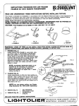
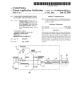
1
ITEM #0144477
MAZON CEILING FAN
allen+ rotli
a b ac kdr o p fo r li v in g .,..
MODEL #3MVR44BSD
UL MODEL #AC-344LF8200H
Espanol p. 16
ATTACH YOUR RECEIPT HERE
Serial Number _ _ _ __ _
Purchase Date - - - - - -
~ Questions, problems, missing parts? Before returning to your retailer, call our customer
t:;i,}
service department at 1-866-439-9800, 8 a.m.- 6 p.m., EST, Monday- Thursday, 8 a.m.- 5
p.m., EST, Friday.
1
TABLE OF CONTENTS
Safety Information .......................... ............................................................................................... 2
Package Contents ............................................................................................................... .......... 4
Hardware Contents ....................................................................................................................... 5
Preparation ........................................................................................................ ........................... 6
Assembly Instructions ....... ........ ............... ....... .. .. .......... ............ ... ........... .... ... ........... .... ............. .. 7
Operation Instructions ........................................ ........................................................................... 12
Care and Maintenance ........................ .. ............................... ....................... .................................. 13
Troubleshooting ................. .. ............. ..... ... .......... ......... .. ........... ...... ............................. ... ... ........... 14
Warranty ................................................... ...................... ................ ....... .. ..................................... 15
Replacement Parts List ........................................ ........................................................................ 15
•
SAFETY INFORMATION
READ AND SAVE THESE INSTRUCTIONS
Please read and understand this entire manual before attempting to assemble, operate or install
the product. If you have any questions regarding the product, please call customer service at
1-866-439-9800, 8 a.m.- 6 p.m., EST, Monday- Thursday, 8 a.m.- 5 p.m., EST, Friday.
• Installation work and electrical wiring must be done by qualified person(s) in accordance with
applicable codes and standards (ANSI/NFPA 70-1999), including fire-rated construction.
• Before you begin installing the fan, servicing or cleaning unit, switch power off at service panel
and lock service disconnecting means to prevent power from being switched on accidentally. When
the service disconnecting means cannot be locked, securely fasten a prominent warning device,
such as a tag, to the service panel.
• Use this unit only in the manner intended by the manufacturer. If you have any questions contact
customer service center.
• Make sure the installation site you choose allows the fan blades to rotate without any
obstructions. Allow a minimum clearance of 7 ft. from the floor to the trailing edge of the blade.
• Never place a switch where it can be reached from a tub or shower.
• If this unit is to be installed over a tub or shower, it must be marked as appropriate for the
application.
• The combustion airflow needed for safe operation of fuel-burning equipment may be affected by
this unit's operation. Follow the heating equipment manufacturer's guideline safety standards such
as those published by the National Fire Protection Association (NFPA), and the American Society
for Heating, Refrigeration and Air Conditioning Engineers (ASH RAE) and the local code authorities.
• To reduce the risk of electric shock, disconnect the electrical supply circuit to the fan before
installing the light kit.
• All set screws must be checked and tightened where necessary before installation.
• The net weight of this fan with light kit is: 15.25 lbs. (6.93 kg).
2
A
SAFETY INFORMATION
A WARNING
&
A WARNING
ELECTRIC SHOCK HAZARD
To reduce the risk of electric
shock, do not use this fan with any
solid-state speed control device.
&
SHOCK HAZARD
To reduce the risk of shock, this fan
must be in.stalled with an isolation wall
control/sw1tch.
A WARNING
ELECTRIC SHOCK HAZARD
To reduce the risk of electric shock, make sure electricity has been turned off at the circuit
breaker or fuse box before beginning installation.
I
A WARNING
PERSONAL INJURY HAZARD
To reduce the risk of personal injury, do not bend the blade brackets when installing the
brackets, balancing the blades, or cleaning the fan. Do not insert foreign objects in
between rotating fan blades.
.
AWARNING
FIRE, ELECTRICAL SHOCK OR PERSONAL INJURY HAZARD
To reduce the risk of fire, electric shock, or personal injury, mount to outlet box marked "ACCEPTABLE FOR FAN SUPPORT," (Mounting must support at least 351bs.) and use mounting screws provided with the outlet box. Most outlet boxes commonly used for the support
of lighting fixtures are not acceptable for fan support and may need to be replaced. Consul
a qualified electrician if in doubt.
&
A WARNING
FIRE, ELECTRICAL SHOCK OR PERSONAL INJURY HAZARD
When cutting or drilling into wall or ceiling, do not damage electrical wiring and other hidden
utilities.
I
CAUTION
PERSONAL INJURY HAZARD
To reduce the risk of injury to persons, install fan so that the blade is at least 7ft. (2.1 m) above the
floor.
3
PACKAGE CONTENTS
-·
\\..____lil(JI]Ii)_____,/-.
~-·
-·
Q
•
@-•
-0
PART
A
B
c
D
E
F
G
H
I
J
DESCRIPTION
Mounting plate
Decorative ring
Remote control receiver
Motor assembly
Blade
Light fixture
Internal light fixture
Glass
Bulb
Remote control transmitter
QUANTITY
1
1
1
1
3
1
1
1
1
1
4
HARDWARE CONTENTS (shown actual size)
•
i
Blade screws
Qty. 12
Wire connector
Qty. 3
~.
®
Enhance plate
Qty. 3
Fiber washer
Qty. 12
Extra flate washer
Qty. 2
Extra spring washer
Qty. 2
•
Balance clip
Qty. 1
Extra Wood screw
Qty. 2
Balance weight
Qty. 3
•
•;
Extra light fixture
screw
Qty. 1
Extra canopy mounting
screw
i
0
i
Qty. 1
Extra screw
(For internal ligh~ fixture
installation)
Qty. 1
5
•
Battery
Qty. 1
HARDWARE CONTENTS
Note:
• Extra hardware
are needed.
• Extra hardware
• Extra hardware
• Extra hardware
EE, FF and GG should be used in step 1 in the assembly instructions if they
JJ should be used in step 12 in the assembly instructions if it is needed.
KK should be used in step 8 in the assembly instructions if it is needed.
LL should be used in step 14 in the assembly instructions if it is needed.
PREPARATION
Before beginning assembly of product, make sure all parts are present. Compare parts with
package contents list and hardware contents. If any part is missing or damaged, do not attempt
to assemble the product. Contact customer service for replacement parts.
Estimated Assembly Time: 30 minutes
Tools Required for Assembly (not included): Phillips screwdriver, step ladder, electrical tape,
pliers, wire cutter, wire stripper.
WARNING: Before starting assembly of this product, please disconnect power to area and
familiarize yourself with the safety information provided on page 2 and 3.
6
ASSEMBLY INSTRUCTIONS
1. Install mounting plate (A) to outlet box (not included).
Use only the screws (not included) provided with the
outlet box.
0
/
2. Place decorative ring (B) over canopy on motor
assembly (D).
/
G
/
G
3. Set dip switches on the remote control transmitter (J)
and remote control receiver (C) to the same setting.
This must be done so the units will communicate properly. If you have other fans you can set them to be
controlled by one transmitter by setting both receivers
the same as transmitter. If you have more than one fan
with a remote control, you can set the dip switches to
different positions to have separate control.
-8
cover
7
ASSEMBLY INSTRUCTIONS
4. Loosen two preassembled screws across from each
other and remove the other two screws from mounting
plate (A). Keep screws for later use.
Hang motor assembly (D) onto mounting plate (A)
by the hand-free hook with a closed hole on the
canopy of motor assembly (D).
/
0
/
G
5. Make wire connections as in the wiring diagram.
Connect WHITE wire from motor assembly (D) to
WHITE wire from remote control receiver (C) marked TO
MOTOR N, BLUE wire from motor assembly (D) to
BLUE wire from remote control receiver (C) marked FOR
LIGHT. Connect BLACK wire from motor assembly (D) to
BLACK wire from remote control reciever (C) marked TO
MOTOR L. Connect BLACK (Live) wire from house to
BLACK wire from remote control receiver (C) marked AC
IN L. Connect WHITE (Neutral) wire from house to
WHITE wire from remote control receiver (C) marked AC
IN N. Connect GROUND LEAD (Green) from mounting
plate (A) to GROUND LEAD from house.
6. To connect wires, put wire ends together and screw
wire with wire connector (DO) in a clockwise direction .
Tape the wire connector (DO) and wires together. Make
sure that no filiments are outside of the wire connectors
(DO). After making the wire connections, the wires
should be spread apart with the grounded conductor and
the equipment-grounding conductor on one side of the
outlet box and ungrounded conductor on the other side
of the outlet box. The splices after being made should be
turned upward and pushed carefully up into the outlet
box.
Hardware Used
~
Wire connector
~
x3
8
Grounded
ASSEMBLY INSTRUCTIONS
7. After wire connections, attach remote control
receiver (C) onto the canopy on motor assembly (D) by
preadhered double-sided foam tape as shown.
8. Lift motor assembly (D) up, aligning keyhole slots on
canopy of motor assembly (D) with preassembled
screws on mounting plate (A) . Install the screws
removed in step 4. Tighten all screws securely.
9. Lift the decorative ring (B) up, aligning notches on
canopy of motor assembly (D) with raised areas
on inside of decorative ring (B) and pop it onto
the canopy.
9
Double-sided foam tape
ASSEMBLY INSTRUCTIONS
10. Insert blade (E) into the slot on motor assembly (D)
and install blade screws (AA) and fiber washers (BB) with
enhance plate (CC) aligning each of the holes as shown.
Repeat this process for remaining blades.
Note: Make sure the side with a label "This side up" is
installed upward.
Hardware Used
•
Blade screw
~.
Fiber washer
~
Enhance plate
~
®
c
fP
x9
x9
~
x3
11 . Loosen two and remove one preassembled
screw from plate on motor assembly (D).
12. Connect plug from fan to plug from light
fixture (F). Make sure plugs are connected
securely.
Attach the light fixture (F) onto plate on motor
assembly (D) by aligning its keyhole slots
with preassembled screws on the plate and
twist to lock. Re-install the screw removed in step 11 .
Tighten all screws securely.
10
ASSEMBLY INSTRUCTIONS
13. Loosen two and remove one preassembled
screw from light plate in light fixture (F). Save
screw for later use.
14. Connect white wire from light fixture (F) to white
wire from internal light pan (G). Connect blue wire
from light fixture (F) to black wire from internal
light fixture (G).
Install internal light fixture (G) to light fixture (F) by
aligning its keyhole slots with the preassembled
screws on the light fixture (F) and twist to lock.
Re-install the screw removed in step 13 and tighten all
screws securely.
15. Install bulb (1). Attach glass (H) by aligning
dimples in internal light fixture (G) with the grooves
in glass (H) and twist clockwise until tight.
WARNING: This item used one (1) 75-watt JDE11
base halogen bulb. Exceeding the maximum
wattage of this item will result in the fan light
shutting down until the proper wattage of bulbs are
installed. Reset the light by turning off, replacing
bulbs with the correct wattage and turning the power
back.
Note: Do not replace bulb until it cools down.
11
OPERATION INSTRUCTIONS
Turn on the power and check operation of fan.
Speed settings for warm or cool weather depend on
factors such as room size, ceiling height and number of
fans.
The slide switch controls direction, forward (left) or
reverse (right).
Note: Turn off and wait for fan to stop before changing
the setting of forward/reverse function.
Warm weather- (Forward) Fan turns in a
counterclockwise direction. A downward air flow creates
a cooling effect as shown in Illustration A of figure 2.
This allows you to set your air conditioner on higher
temperature settings without affecting your comfort.
Slide (reverse) switch
Cool weather- (Reverse) Fan turns in a clockwise
direction. An upward air flow moves warm air off the
ceiling area as shown in Illustration B of figure 2. This
allows you to set your heating unit on lower settings
without affecting your comfort.
REMOTE CONTROL TRANSMITTER
1. Remove the battery cover from the remote control
transmitter (J), and install battery (MM). Replace the cover.
Note: Use 12-volt battery to replace battery (MM).
2. The buttons on remote control transmitter (J) control the
fan speed and light as follows.
0 Low speed
00 Medium speed
000 High speed
0
~
Turn the fan off
Press light key quickly to turn light on or off.
Press and hold the button to dim the light. The light
will cycle from bright to dim to bright until button is
released. Light will maintain last setting if turned off.
Batte
12
cover
CARE AND MAINTENANCE
Important: Shut off main power supply before beginning any maintenance.
• Because of the fan's natural movement, some connections may become loose. Check the support
connections, brackets and blade attachments twice a year. Make sure they are secure.
• Clean your fan periodically to help maintain its new appearance for years. Do not use water while
cleaning. This could damage the motor, or the wood, or possibly cause electrical shock.
• Use only a soft brush or lint-free cloth to avoid scratching the finish. The plating is sealed with a
lacquer coating to minimize discoloration or tarnishing .
• There is no need to oil your fan . The motor has permanently lubricated bearings.
13
TROUBLESHOOTING
If you have any questions regarding the product, please call customer service at 1-866-439-9800, 8
a.m. - 6 p.m. , EST, Monday- Thursday, 8 a.m. - 5 p.m. , EST, Friday.
PROBLEM
POSSIBLE CAUSE
CORRECTIVE ACTION
Fan doest not start
1. Power is off.
2. Pull chain switch is off.
3. Reverse switch does not engage.
4. Faulty wire connection.
5. Out of battery (Transmitter).
6. Dip switchs does not match.
1. Check main and branch fuses
or circuit breakers.
2. Pull the pull chain switch.
3. Push the switch firmly either
way.
4. Turn power off and check all
wire connections.
5. Replace battery.
6. Check dip switches setting.
Fan sounds noise
1. Set screws are loose.
2. Faulty light bulb installation.
3. Glass is not secure.
4. Unapproved speed control.
1. Tighten all set screws.
2. Check to be sure light bulb is
tight in cocket and not touch
on glass shade.
3. Secure the glass.
4. Replace with an approved
speed controller.
Excessive wobbling
1. Blades or blade holders are loose.
2. Unbalanced blades.
3. Mounting bracket is not secure.
4. Set screws on yoke are not secure.
5. Downrod ball does not engage.
6. Fan too close to vaulted ceiling.
1. Tighten all set screws of blades
and blade holders.
2. Switch blade with a blade from
the opposite side.
3. Turn power off. Loosen canopy
and make sure that mounting
bracket is secure.
4. Tighten the set screws.
5. Make sure that the ridge on
mounting bracket engages the
notch in the downrod ball.
6. Use longer downrod or move it
to other locations.
Light does not work
1.
2.
3.
4.
5.
1. Turn power off and check all
wire connections.
2. Remove light kit and check plug
connection.
3. Replace bulbs.
4. Turn power off. Reinstall bulbs.
5. Turn power off and replace with
correct bulbs. Turn power on.
6. Replace battery.
7. Check dip switch setting.
.
Faulty wire connection.
Faulty plug connection.
Faulty light bulbs.
Bulbs does not install well.
Over Iamping and result in the light
shut down .
6. Out of battery (Transmitter).
7. Dip switches does not match.
14
WARRANTY
The manufacturer warrants this fan to be free from defects in workmanship and material present
at time of shipment from the factory for lifetime limited from the date of purchase. This warranty
applies only to the original purchaser. The manufacturer agrees to correct such defect at no change
or at our option replace the ceiling fan with a comparable or superior model.
To obtain warranty service, present a copy of your sales receipt as proof of purchase. All cost of
removal and reinstallation are the expressed responsibility of the purchaser. Any damage to the
ceiling fan by accident, misuse or improper installation, or by affixing accessories not produced by this
the manufacturer of the fan, are at the purchaser's own responsibility. The manufacturer assumes
no responsibility whatsoever for fan installation during the lifetime limited warranty. Any service
performed by an unauthorized person will render the warranty invalid.
Due to varying climatic conditions, this warranty does not cover changes in brass finish, rusting,
pitting, tarnishing, corroding or peeling. Brass finish fans maintain their beauty when protected from
varying weather conditions. Any glass provided with this fan is not covered by the warranty.
Any replacement of defective parts for the ceiling fan must be reported within the first year from the
date of purchase. For the balance of the warranty, call our customer service department at
1-866-439-9800 for return authorization and shipping instructions so that we may repair or replace
the ceiling fan. Any fan or parts returned improperly packaged is the sole responsibility of the
purchaser. There is no further expressed warranty. The manufacturer disclaims any and all
implied warranties.
The duration of any implied warranty which can not be disclaimed is limited to the lifetime limited
period as specified in our warranty. The manufacturer shall not be liable for incidental,
consequential or special damages arising at or in connection with product use or performance
except as may otherwise be accorded by law. This warranty gives you specific legal rights and you
also have other rights which vary from state to state. This warranty supersedes all prior warranties.
Note: A small amount of "wobble" is normal and should not be considered a defect.
REPLACEMENT PARTS LIST
m __ 0
For replacement parts, call our customer service department at 1-866-439-9800, 8 a.m. - 6 p.m., EST,
Monday- Thursday, 8 a.m. - 5 p.m., EST, Friday.
C)-o
PART
A
B
DESCRIPTION
Mounting plate
decorative ring
c Remote control receiver
E
Blade
F
Light fixture
G
Internal light fixture
H
Glass
I
Bulb
J
Remote control transmitter
AA-MM Hardware pack
~
PART#
101240
108319
100071
131919
133568
133569
G635
160010
100072
102749
G
C3
8-l
§]
AA-MM
~
0
~~~ G
e-o
Printed in China
15