1
Installation and Operating Manual
Heat Pump Water Heater
with Sheet-Metal Cabinet, Airduct Connection
and Supplementary Heat Exchanger
AWP 300 LW
451901.67.19
FD8405
TABLE OF CONTENTS .......................................................................................................................... Page
1.
Regulations / Safety Notices ..................................................................................................... 3
2.
2.1
2.2
2.3
Description.................................................................................................................................. 3
Refrigeration Cycle....................................................................................................................... 4
Water Circuit................................................................................................................................. 4
Safety Devices ............................................................................................................................. 5
3.
3.1
3.2
3.3
3.4
3.5
Controlling and Operating Concept.......................................................................................... 5
Operating Panel of HPWH ........................................................................................................... 5
Hot Water Temperature Controller ............................................................................................... 6
'Heat Pump' Switch ...................................................................................................................... 6
'Immersion Heater' Switch ............................................................................................................ 6
'Heat Exchanger' Switch............................................................................................................... 7
4.
4.1
4.1.1
4.1.2
Storage / Transport .................................................................................................................... 7
Storage and Transport of HPHW ................................................................................................. 7
Transport Using a Forklift ............................................................................................................. 7
Manual Transport ......................................................................................................................... 7
5.
5.1
5.2
Installation .................................................................................................................................. 8
Installation Site ............................................................................................................................. 8
Installation .................................................................................................................................... 8
6.
6.1
6.2
6.3
6.3.1
Mounting ..................................................................................................................................... 9
Connection of Water Piping.......................................................................................................... 9
Connection of Condensate Line ................................................................................................... 9
Electrical Connection.................................................................................................................... 9
Opening the Cabinet .................................................................................................................. 10
7.
7.1
7.1.1
7.1.2
Commissioning ........................................................................................................................ 10
Hot Water Circuit ........................................................................................................................ 10
Hot Water Circuit Requirements................................................................................................. 10
Commissioning of Hot Water System......................................................................................... 11
8.
8.1
8.2
8.3
Maintenance/ Service............................................................................................................... 11
Water Circuit / Condensate Drain............................................................................................... 11
Air Supply ................................................................................................................................... 11
Sacrificial Anode......................................................................................................................... 12
9.
Malfunctions / Troubleshooting .............................................................................................. 12
10.
Decommissioning .................................................................................................................... 13
11.
Environmental Requirements ................................................................................................. 13
12.
12.1
12.2.1
12.2.2
12.3
12.4
Appendix ................................................................................................................................... 13
Refrigeration Cycle with Legend ................................................................................................ 13
Hydraulic Plumbing Diagram...................................................................................................... 14
Heat Exchanger Plumbing Diagram (Ex.: Thermal Solar System) ............................................. 14
Circuit Diagram........................................................................................................................... 15
Technical Data ........................................................................................................................... 16
Warranty Certificate........................................................................................................................
EC Declaration of Conformity .........................................................................................................
(HPWH = abbreviation used in the following for Heat Pump Water Heater)
Page 2 of 20
1.
Regulations / Safety Notices
(
This installation and operating manual must be read before the unit is started up!
)
¾#The heat pump water heater (HPWH) is designed exclusively for the heating of domestic or potable water within the specified operating temperature limits!
¾ In the design and construction of the HPWH, all relevant EC directives were complied with (see also EC
Declaration of Conformity).
¾ A qualified, experienced technician must ensure that prior to the commencement of any maintenance/repair activities on refrigerant-carrying parts, the refrigerant has been removed to such an extent
as necessary for the safe performance of this work. The refrigerant must be handled and disposed of in
accordance with applicable regulations and must not be released into the atmosphere! (Refrigerant
R134a is CFC-free, non-flammable and has no ozone-depleting properties).
¾ When working on the HPWH, the unit must always be disconnected from the power source (pull the plug).
¾ The electrical connection of the HPWH must be performed according to and conforming with all relevant
VDE, EN and IEC standards. Beyond that, the technical connection requirements of the local utility companies have to be observed.
Caution!
Any work on the hot water heat pump may only be performed by qualified persons! All relevant accident prevention regulations have to be observed!
2.
Description
The HPWH is a heating appliance ready for connection and essentially consists of a domestic water tank,
the components of the refrigeration, air and water circuits as well as all control, regulating and monitoring
devices required for automatic operation.
The HPWH uses electricity to extract the heat from the drawn-in air for the generation of hot water. The
HPWH appliance type featuring an internal heat exchanger is suited for connection to a supplementary heat
source such as a boiler or solar system. A vertical well (inside ∅ ≥ 12 mm) is provided to accommodate an
external temperature sensor. The units are equipped with an electric immersion heater (1.5 kW) as standard.
The electric immersion heater fulfils four functions:
„#Supplementary
heater
Activating the immersion heater (via "Immersion heater" switch, see Section 3.4) in addition to the heat
pump approximately halves the water heating recovery time.
„#Frost
protection
Any time the temperature of the drawn-in air drops below 8 °C, the heat pump switches off and the
electric immersion heater is automatically switched on; the latter heats the water (only) until the preset
setpoint temperature is reached.
„#Emergency
heat
The electric heating element (immersion heater) will maintain the hot water supply when the heat pump
requires servicing.
„#Higher
water temperature
If the required hot water temperature is higher than the temperature that can be reached by the heat
pump (approx. 55 °C), the temperature can be increased to max. 85 °C by the immersion heater.
Note:
For hot water temperatures > 55 °C the heat pump is switched off, and water heating
is accomplished by the immersion heater only.
Page 3 of 20
2.1
Refrigeration Cycle
The refrigeration cycle is a closed system in which the refrigerant R134a circulates as an energy carrier. In a
finned heat exchanger, heat is extracted from the drawn in air at a low evaporation temperature and transferred to the refrigerant. The vaporous refrigerant is drawn in by a compressor and then compressed to a
higher pressure/temperature level; it is passed to the condenser where the heat absorbed in the evaporator
and part of the heat of the compressor motor is transferred to the water. Subsequently, the high condensing
pressure is reduced by means of a throttling device (expansion valve) to the level of the evaporating pressure, and in the evaporator the refrigerant can again absorb heat from the drawn-in air.
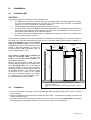
2.2
Water Circuit
The water circuits of the HPWH are dependent on the specific type (with or without internal heat exchanger).
They have to be field-installed. The water connections (Fig. 1) are located at the rear of the unit.
Important Notes!
-
Circulation line
From an energy-efficiency point of view, the provision of a circulation line should be dispensed with, if
possible.
If a circulation line for the hot water distribution system is connected, it must be fitted with a valve or similar device enabling it to be shut off to avoid any unnecessary loss of energy. Enabling the circulation is effected as required (time or on-demand control).
-
Condensate drain: note Section 6.2 "Connection of Condensate Line".
660
Ø160
Power supply /
cable entries
Ø160
1650
1610
Hot water outlet
R1" external thread
1206
1)
Circulation line
R 3/4" external thread
Hot water supply
R1" external thread
898
ca. 30
700
Condensate hose
(brought out at bottom)
Heating water return
R1" external thread
Cold water supply
R1" external thread
200
35
0
max. 50
1) alternative condensate hose routing
Fig. 1: Water connections
Page 4 of 20
2.3
Safety Devices
The HPWH is equipped with the following safety features:
2.3.1
High-Pressure Pressostat (HP)
The high-pressure pressostat protects the heat pump from excessive operating pressures in the refrigeration
cycle. In the case of a malfunction, the pressostat switches off the heat pump. The heat pump is restarted
automatically as soon as the pressure in the refrigeration cycle has dropped to an acceptable level.
2.3.2
Safety Temperature Limiter for Immersion Heater (STL)
Partition
The STL protects the hot water installation from excessive temperature increases.
It is secured to the switch box panel, and the associated sensor is
located in the well of the immersion heater.
STL
When the preset switching value (99 °C) is exceeded, the immersion heater is switched off.
The immersion heater cannot be restarted unless the hot water
temperature has fallen to ≤ 90 °C and the reset button (Fig. 2) on
the STL has subsequently been pressed.
85°
B3
F2
30°
Reset button
Operating panel
Important Note!
Bild 2 : STB
- The safety temperature limiter can be accessed after the
operating panel has been removed. Any interventions may therefore only be performed by qualified persons. Prior to opening the unit, the appliance must be disconnected from the power supply!
3.
Controlling and Operating Concept
3. 1 Operating Panel of HPWH
Analog display
of hot water temperature
'Heat pump'
switch
'Immersion
heater'
switch
'Heat exchanger'
switch
Hot water
temperature dial
Fig. 3: Operating panel of HPWH
Page 5 of 20
3.2
Hot Water Temperature Controller
The desired hot water temperature can be set using the rotary dial. If the storage tank temperature is lower
than the preset hot water temperature setpoint value, the heat pump is activated (provided the 'Heat pump'
switch is set to On).
The heat pump can achieve hot water temperatures of max. 55 °C. If higher temperatures are desired, the
immersion heater, provided as standard, can be used (see Section 3.4).
Notes for efficient energy consumption
Ö For a high coefficient of performance of the integrated heat pump and low standby losses, the HWHP
should not normally be operated at water temperatures in excess of 45 °C (Fig. 4).
Ö Only in exceptional cases should the temperature control be set to a higher value or the
immersion heater be activated manually.
Ö To ensure optimum compressor runtimes and
a long compressor life, the heat pump should
not be manually switched on and off in quick
succession!
~ 45 °C
~ 27 °C min.
max. ~
55 °C
Fig. 4: Energy-saving setting
3.3
'Heat Pump' Switch
When the 'Heat pump' switch is placed in the 'On' position, the heat pump is ready for operation. When the
hot water temperature in the storage tank drops below the preset setpoint value, the heat pump is activated
until the desired hot water temperature is reached.
When the switch is in the 'Off' position, the operation of the heat pump is disabled. However, the hot water
temperature controller continues to be active and allows a tank charging pump of an additional heat exchanger to be activated via the 'Heat exchanger' relay output. In this case, the 'Heat exchanger' switch must
be in the 'On' position.
3.4
'Immersion Heater' Switch
The integrated 1.5 kW heating element can be activated by means of the 'immersion heater' switch when
there is an increased demand for hot water or a higher hot water temperature (> 55 ±2 °C) is desired.
When the 'immersion heater' switch is in the 'On' position, the storage tank content is heated up to the setpoint temperature of the immersion heater controller (factory setting 65 °C); for hot water temperatures > 55
°C, hot water preparation takes place exclusively via the immersion heater.
Although the 'Immersion heater' switch is in the 'OFF' position, the immersion heater will switch on automatically if there is a danger of frost (at air intake temperatures of 8 ±1,5°C); the water is then (only) heated until
the preset hot water temperature setpoint is reached.
-
Note!
Immersion heater controller
The immersion heater controller is a second control device for the operating range of the immersion heater
that operates independently of the hot water controller. The switch-off temperature is factory-set at 65 °C.
The immersion heater controller operates in conjunction with the safety temperature limiter (see Fig. 2).
If a different temperature setpoint is required, it should be kept in mind that the controller is not accessible
until the upper front panel has been removed (see Fig. 8). The intervention may therefore only be performed
by qualified persons. Prior to opening the unit it must be disconnected from the power supply!
Page 6 of 20
3.5
'Heat Exchanger' Switch
The heat exchanger mode is used whenever hot water preparation is to take place by means of a supplementary heat source (e.g. in winter by means of a boiler). The standard relay contact, for example, can be
used – through activation of the pump or valve – to charge the hot water tank by means of the heat exchanger coil integrated in the tank.
The hot water temperature is regulated by the temperature controller of the HPWH.
The supply terminal for the control (ON/OFF)
of the external auxiliary devices (pump, solenoid valve, etc.) is located on the switch box
panel.
This function is activated by the "heat exchanger" switch.
free
cable bushing
In addition, on the rear of the HPWH a vertical
sensor well (∅ 12 mm) is provided on the
storage tank (accessible via the electrical
connecting box). An external temperature
sensor can be inserted here. A free cable
bushing is provided in the rear panel.
Zugentlastungen
sensor immersion well
Fig. 5: Immersion well, top view
4.
4.1
STORAGE / TRANSPORT
Storage and Transport of HPWH
As a rule, the HPWH is to be stored and/or transported in its shipping container in upright position and without water charge. For a transport over short distances, and provided due care is exercised, an inclination
angle of up to 45° is permitted. Both during transport and storage, ambient temperatures of -20 to
+70 °C are permissible.
4.1.1 Transport Using a Forklift
When transported by a fork lift, the HPWH must remain mounted on the pallet. The lifting rate should be kept
to a minimum. Due to its top-heaviness, the HPWH must be secured against tipping over.
Lowering the HPWH: To prevent any damage, the HPWH must be placed on a level surface!
4.1.2 Manual Transport
For the manual transport, the wooden pallet can be used for the bottom
part. Using ropes or carrying straps, a second or third handling
configuration is possible. With this type of handling (applies to the
transport by hand cart as well), care must be taken that the max.
permissible inclination angle of 45° is not exceeded (see Fig. 6). If
transport in an inclined position cannot be avoided, the HPWH ("heat
pump" switch) should be taken into operation one hour after it has been
moved into final position at the earliest (see also Section 7).
Fig. 6
Caution! The (painted) sheet-metal panel assemblies, in particular the upper panel assemblies, are not
designed to withstand the weight of the unit!
CAUTION!
High center of gravity , low overturning moment !!
Page 7 of 20
5.
Installation
5.1
Installation Site
CAUTION!
The following applies to the selection of the installation site:
¾
The HPWH must be sited in a freeze-proof room (preferably within the building thermal envelope).
The room air temperature and/or the air taken in by the HPWH should be within a temperature
range of 8 °C to 35 °C (required for heat pump operation).
¾
A field-installed condensate drain (with siphon) must be provided.
¾
The floor surface must have adequate load bearing capability (the estimated weight of the plant is
475 kg when fully charged). When installed on an upper floor, utmost attention must be paid to vibration decoupling measures for acoustic attenuation.
¾
The HPWH must not be installed in areas or operated with exhaust air if there is an explosion hazard due to dust, gases or vapours.
If the ceiling is lower and no airducts are
used, an air ducting elbow (90° NW 160)
must be used on the outlet air side (to ensure effective operation).
When an air ducting elbow is used, care must
be taken that it is slipped onto the flange collar
of the discharge side in such a way that the
discharge opening of the air ducting elbow is
as far away from the intake opening of the unit
as possible. Moreover, the minimum clearances shown in Fig. 7 have to be complied
with. The air connection fittings of the HPWH,
i.e. "intake connector" and "discharge connector“ are identified by adhesive labels.
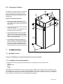
5.2
Installation
2.3 m * )
For trouble-free operation as well as the performance of maintenance and repair work, minimum clearances
of at least 0.6 m must be maintained all around the unit. A minimum ceiling height of approx. 2.50 m is required for operation of the HPWH without
discharged air
airducts or airduct elbows (➠ "free-blowing“
drawn-in
installation) (see Fig. 7). The connection to the
air
HPWH is effected (optionally) by means of
0.6 m
1.2 m *)
insulated airducts (NW 160) which must not
exceed a total length of 10 m.
* ) the minimum distance of the discharge opening of the airducting
elbow to the wall is 1.2 m
The minimum ceiling height for "free-blowing installation“ is approx.
2.5m
Fig. 7: Minimum Clearances
¾ From the underside of the pallet, remove the three M12 bolts securing the pallet to the unit as a shipping
safety measure.
¾ Remove the pallet and mount the three levelling feet (M12 bolts – contained in the polybag, secured to the
storage tank pipe nipple).
¾ Move the HPCDW into final position and adjust the unit so that it is perfectly perpendicular by adjusting
the levelling feet! Subsequently, tighten the check nuts provided on the levelling feet.
Page 8 of 20
6.
Mounting
6.1
Connection of Water Piping
The nominal pipe widths of the field-installed sanitary installations must be selected on the basis of the available water pressure and the expected pressure drop within the piping system.
The water-side installation has to be executed in compliance with DIN 1988 (see appendix – in the case of
excessive water pipe pressure, a pressure relief valve is to be provided, among other things!)
The water pipes may be of the rigid or flexible type. To prevent corrosion damage, make sure that the materials used in the piping system are compatible (see section Commissioning).
Caution!
6.2
When installing the pipework on the customer's site, any contamination of the piping
system must be avoided (pipes may have to be flushed prior to the connection of the
HPWH)!
Connection of Condensate Line
The condensate hose is passed through the rear panel of the unit. It must be routed in such a way that any
condensate which may collect can drain without any obstruction. When the unit is delivered, the condensate
hose is passed through the bottom of the rear panel and can thus be used for condensate drainage near
ground level. For condensate drains located at a higher level, the condensate hose can be routed through
the upper opening (Fig. 1). With this type of routing it is imperative that a minimum height difference of
260 mm be maintained between the condensate hose outlet opening (on the unit) and the condensate hose
end (e.g. in a siphon).
At the end of the condensate hose a sealing lip valve (that opens without pressure) is provided which must
also be relocated when the condensate hose is shortened (valve can be easily removed and reinstalled on
the hose).
6.3
Electrical Connection
The HPWH is pre-wired, ready for connection, the power is supplied via the mains cable connected to a wall
outlet with earthing contact (~230 V, 50 Hz). This outlet must be accessible also after the installation has
been completed.
For the control of external devices for the supplementary heat source, a separate wire must be fed into the
unit. For this purpose, the HPWH must be opened as described under 6.3.1. The cable must also be passed
through the partition in that it is guided through a free cable bushing provided for this purpose. The terminal
(X5 – 4/5/PE) with a potential-free contact for the control (ON/OFF) of the external ancillary equipment
(pump, solenoid valve, etc.) is located on the partition inside the unit. The cable must be inserted into the
provided strain relief (Fig. 5) and secured.
External immersion heater control
As an option, it is possible to configure the immersion heater in such a way that in addition to the activation
by the "immersion heater" switch on the operating panel on the HPWH it is also possible to activate the electric heating element remotely (e.g. by using a timer). A potential-free contact on the external switchgear must
2
be available for this connection; in addition, another wire (min. 2 x 1.0 mm / max. outside dia. 10 mm) must
be introduced into the unit and clamped to terminals 6 and 7 of terminal strip X5.
Fig. 8: Terminal in the appliance
4
5
6
/
1
3(
3(
7
8
9
:
4
5
6
/
1
3(
3(
7
8
9
:
X5
( X3 – only internal wiring )
X5 (4 + 5) Terminal, potential-free contact
for supplementary heat source
X5 (6 + 7) Terminal for external immersion
heater control (option)
X3
Page 9 of 20
6.3.1 Opening the Cabinet
3
For feeding in an external cable or inserting a
sensor, the "upper side panel" (2) and the
"upper front panel" (1) must be removed; to
this end, the "top cover" (3) need to be loosened as well.
b
1
approx. 6 m m
Sequence of dismantling steps :
c
1. Remove the "upper front panel" (1) by
loosening the (two) sheet metal screws (a)
and raising the front panel in the direction
of the arrow.
2. Loosen the two rear sheet metal screws (b)
on the top cover (3);
Slide cover approx. 6 mm toward the rear
(in direction of arrow) and raise.
3. Loosen the two screws (c), move "upper
side panel" (2) away from the rear panel
(approx. 20 mm), slide "upper side panel"
approx. 6 mm toward the front (in direction
of arrow), raise and remove.
approx. 6 m m
approx. 20 mm
2
a
4
4. To remove the "bottom front panel" (4)
(only required for checking the sacrificial
anode or the immersion heater) it suffices
to loosen the lower two fastening screws
(d) and to slide the "bottom front panel"
6 mm toward the top and then to remove it.
7.
COMMISSIONING
d
Fig. 9: Opening the HPWH
7.1 Hot Water Circuit
Caution! The HPWH may only be operated with the unit filled with water!
7.1.1 Hot Water Circuit Requirements
On the consumer side, the following materials may be incorporated into the hot water circuit:
- Copper
- Stainless steel
- Brass
- Plastic
Depending on the materials used in the hot water circuit (installation to be provided by the customer), corrosion damage may occur due to material incompatibilities. This must be taken into account, in particular
where galvanised materials and those containing aluminium are used. A filter may have to be provided if
there is a danger of water becoming contaminated during operation.
Page 10 of 20
7.1.2 Commissioning of Hot Water System
•
Fill hot water circuit via the external connection.
•
Vent the hot water circuit
(open hot water taps at the topmost points of use until no more air escapes).
•
Perform a leak test of the entire hot water circuit.
•
Connect the unit to the power supply (insert plug into wall outlet).
•
Turn on the heat pump switch (Fig. 3).
•
The desired hot water temperature is infinitely adjustable (up to 55 °C) by means of the temperature
dial (Fig. 3).
•
At air intake temperatures below 8°C or if there is an increased demand for hot water, the electrical immersion heater is activated automatically or manually (Fig. 3).
•
Water heating by means of a supplementary heat source is possible by switching on the heat exchanger charging pump (Fig. 3) (provided the required electrical connection has been established).
8.
Maintenance / Service
Caution!
Always disconnect the mains plug from the power supply prior to opening the HPWH;
be careful as fan may still be rotating!
General
No maintenance activities need to be performed on the refrigeration circuit of the heat pump. For cleaning
the HPWH, simply use a damp cloth and some soapy water. Caution! Do not allow water to come in contact
with operating controls.
A few days following the commissioning procedure, a visual check for possible leaks in the water system or
clogging of the condensate drain is to be performed once.
8.1
Water Circuit / Condensate Drain
The service of the water circuit is limited to the inspection of filters that may have been field-installed, and the
performance of leak tests. Contaminated water filters must be cleaned and replaced, if necessary. The sealing lip valve provided at the condensate hose end must be periodically checked for contamination and be
cleaned, if necessary.
8.2 Air Supply
Maintenance activities are limited to cleaning the evaporator (using a vacuum cleaner) on a regular basis, or
as required.
Caution! There is a hazard of injury from sharp-edged fins. Fins must not be distorted or damaged!
If air filters are used, they must regularly be checked for contamination and be cleaned or replaced, if necessary.
Page 11 of 20
8.3
Sacrificial Anode
The sacrificial anode rod installed in the hot water tank for corrosion protection purposes must be checked
electrically on a regular basis - at least every two years - after commissioning and be replaced, if necessary. The electrical check is to be conducted by means of a suitable ammeter without draining the water in
the tank.
Procedure:
n
o
p
Withdraw PE conductor from tab of sacrificial anode.
Connect ammeter (0...50 mA) between PE conductor and tab.
Evaluation of wear of sacrificial anode:
Measured value > 1 mA ➪ sacrificial anode is okay.
Measured value < 1 mA ➪ sacrificial anode must be checked or replaced.
If an unambiguous electrical check is not possible, we recommend that a visual inspection of the sacrificial
anode be performed. For a replacement of the sacrificial anode that may be necessary [to be performed by a
qualified technician], the water must be drained from the storage tank via the drain valve (to be provided upon
installation – see appendix.
Caution: Sacrificial anodes that are impaired in their function will reduce the life of the unit!
9.
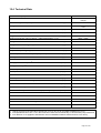
Malfunctions / Troubleshooting
( intended for the user )
Caution!
Work on the heat pump water heater may only be performed by qualified persons!
Accident prevention regulations must be adhered to!
Heat pump fails to run!
Please check that
Ö
Ö
Ö
Ö
Ö
Ö
the plug is plugged in
the power switch is switched on
voltage is present at the wall outlet
the air intake temperature is ≥ 8°C
the heat pump was not switched off by the thermostat
the hot water temperature has not reached or exceeded 55°C
Heat pump switches off prematurely (setpoint temperature has not been reached yet)
Please check whether
Ö
ventilation ducts are kinked or their openings closed, or
air filters that may be provided are severely contaminated (clogged)
Condensate fails to drain ( water present at or under the unit)
Please check whether
Ö
the sealing lip valve at the end of the condensate hose is contaminated or
clogged; clean it, necessary. The valve can be easily removed and reinstalled.
Ö# the air supply / air discharge rate is greatly reduced
(kinked airduct / clogged air filter)
If the malfunction cannot be corrected based on the above questions, please consult your installer or
customer service.
Page 12 of 20
10.
Decommissioning
Activities to be performed:
•
•
Disconnect HPWH from the power source.
Completely shut off water circuit (hot water, cold water and circulation line) and drain the hot water storage tank.
11.
Environmental Requirements
Environment-relevant requirements regarding the recovery, reuse and disposal of service fuels and components in accordance with DIN EN 378 must be adhered to when repairing or decommissioning the HPWH.
12
Appendix
12.1
Refrigeration Cycle with Legend
18
14
TI-CO-L
15
TC
16
13
18
4
1
11
TI
10
TI
17
-CO-H
-C I -L
7
6
9
TI-CO-H
8
TI
-CO-H
-C I -L
3
free immersion well
1
2
3
4
5
6
7
12
2
PA-CO-H
Compressor
Pressostat HP
Condenser
Hot water tank
Heat exchanger (not all types)
Immersion heater
Sacrificial anode
8
9
10
11
12
13
14
Temperature control, heat pump
Safety temperature limiter
Temperature control, immers. heater
Temperature display
Filter drier
Expansion valve
Air temperature thermostat
15
16
17
18
Evaporator
Fan
Check valve
Insulation
Page 13 of 20
12.2.1 Hydraulic Plumbing Diagram
7
hot water
circulation (if required)
1
1
4
8
heating water supply
heating water return
1
4
5
2
3
1
6
cold water connection as per DIN 1988
9
1
2
Shut-off valve
4
Pressure reducing valve 5
3
Test valve
6
Non-return valve
Manometer connection
(to be mounted above tank edge)
Drain valve
7
8
Diaphragm safety valve
Circulating pump
9
Drain
12.2.2 Heat Exchanger Plumbing Diagram
(Example: Thermal Solar System)
Vent
Heat exchanger
flow
Check valve
Stop-cock
Thermometer
from
collector
Safety
valve
Pressure gauge
Catchpan
Flowmeter
Check valve
Heat exchanger
return
Stopcocks
Circulating
pump
Stop-cock
to collector
Charging pump
Expansion vessel
Page 14 of 20
Fan
Ven tila
tor
X3
Electric
heating
element
E le ktro
- H eizstab
Compressor
Verdich ter
L
12.3
W Heat
ärm e pump
pum pe
Potential-free contact for
P o t.-freie r K on takt
immersion heater control
für H eizstaba nst.
230V AC min. 8A
23 0V A C m in . 8A
PE
+ 27..+ 55 °C
B1
X 5-6
1
T>
11
2
1
S2
K4
14
2
X 5-7
+ 8°C
11
Circuit Diagram
N
1
B2 T<
K3
14
3
2
X1
L/N /P E 2 30VA C 50 H z
1
S3
schblack
w arz
+ 65°C
C1
1
K2
green/yellow
grü n/ge lb
1
B3/
F2
S1
P
C
M
B1B 1 Operating
B e trie bthermostat
sth e rm o sta t
B2B 2 AirLtemperature
u ftte m p e rathermostat
tu rth e rm o sta t
B3B 3 Regulating
electr.
heating
R e g e lththermostat,
e rm o sta t-E
l.H e izu
ng
C 1 Starting
A n la ucapacitor,
fko n d e ncompressor
sa to r-Ve rd ich te r
C1
C 2 Operating
B e trie bcapacitor,
sko n d e nfan
sa to r-Ve n tila to r
C2
l.H e izstaheater
b
E1E 1 El.Eimmersion
D -P re sso sta t
F1F 1 HPHpressostat
S ichlimiter
e rh e itsb
e g re n ze
r-T h heating
e rm o sta t
F2F 2 Safety
thermostat,
electr.
E l.Hcompressor
e izu n g
F3 Klixon,
F3
K lixo n -Ve rd ich te r
K1 Relay, ext. pump
K 1 R e la is-e xt.P u m p e
K2 Starting relay, compressor
K 2 A n la u fre la is-Ve rd ich te r
K3 All-or-nothing relay, HP pressostat
K 3 S ch a ltre la is H D -P re sso sta t
K4K 4 Relay,
heater
R e laimmersion
is H e izsta
b
M1
M 1 Compressor
Ve rd ich te r
M2
M 2 Fan
Ve n tila to r
S1S 1 „ON/OFF“
S ch a lteswitch,
r "E INheat
/A U pump
S " W ä rm e p u m p e
S2S 2 „ON/OFF“
S ch a lteswitch,
r "E INel.
/A heater
U S " E l.H e izu n g
S3S 3 „ON/OFF“
S ch a lteswitch,
r "E INexternal
/A U S " pump, heat exchanger
e xteheat
rn e pump
P u m pON/OFF
e -W ä rmvia
e ta
u sch econtrol
r
S4 Switch,
remote
N e tzste
cke r switchover via remote control
S5X 1 Switch,
fan speed
K le m
m le iste F e rn b e d ie n u n g
X1X 2 Mains
plug
K le m mstrip,
le iste
in te rn
X2X 3 Terminal
remote
control
X 5 K le m mstrip,
le iste
-N e tz/p o t.fre ie r K o n ta kt
X3 Terminal
internal
X5 Terminal strip, mains/potential-free contact
(bn )
F3
Legende
Key
2
(+ 30 - + 8 5°C )
10
T>
11
TR
STB
+ 99°C
2
12
L
H2
PE
N
A
M1
21 bar
(bl)
F1
X5
5
1
4
E1
P>
X 3-3
A1
11
A2
14
K1
2
H1
22
H3
5
PE
M2
M
21
5
1
C2
X 3-2
5
14
A1
X 3-1
K3
A1
K4
A2
A2
Page 15 of 20
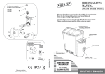
12.4 Technical Data
Exhaust air heat pump water heater
AWP 300LW
with additional internal heat exchanger
Type
Nominal storage tank capacity
(L)
Storage tank material
290
enamelled steel as per DIN
4753
Nominal tank pressure
(bar)
10
Dimensions WxDxH (overall)
(cm)
65 x 70 x 166
Weight
(kg)
approx. 175
Electrical connection (plug-in device – cable length approx. 2.7 m)
230V ~ 50Hz
Fusing
Refrigerant R 134a, charge weight
(A)
16
(kg)
1.0
Performance data
Temperature operating range 2)
(°C)
8 to 35
Water temperature selectable (heat pump mode)
(°C)
23 to 55
Heat-up time from 15° C to 55 °C
(h)
8.25
(Watt)
1500
at 45 °C
(Watt)
550
at 45 °C
(Watt)
1830
Power consumption, electr. back-up heater
Average power consumption
Average heat output
1)
1)
COP(t) as per EN 255
at 45°C
Sound pressure level 3)
Air flow rate:
External pressure
Maximum airduct connection length (total)
Airduct connection, diameter
Internal heat exchanger – transfer surface area
Sensor well Ø inside (for sensor – heat exchanger operating mode)
3.4
(dB(A))
53
3
(m / h)
450
(Pa)
100
(m)
10
(mm)
160
2
(m )
( mm )
1.45
12
Connection
circulation line
external thread
R ¾“
Connection
hot water outlet
external thread
R1“
Connection
cold water feed
external thread
R1“
Connection
internal heat exchanger
external thread
R1“
1) Heat-up process of the rated tank content from 15°C to 45°C at an air intake temperature of 15 °C
2) At temperatures below 8°C ±1.5°C the immersion heater turns automatically on and the heat pump module off
3) At a distance of 1m (applies to stand-alone units or installations without exhaust air duct or 90°-elbow )
Page 16 of 20
Page 18 of 20
Page 19 of 20
KKW Kulmbacher Klimageräte-Werk GmbH
Division Dimplex
Am Goldenen Feld 18
D-95326 Kulmbach
Subject to technical modifications
Fax (0 92 21) 709-589
www.dimplex.de
Page 20 of 20