1
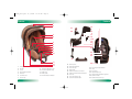
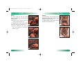
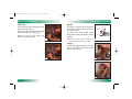
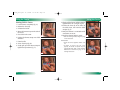
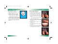
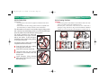
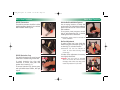
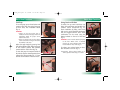
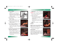
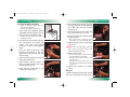
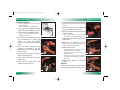
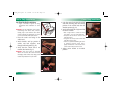
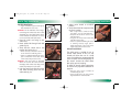
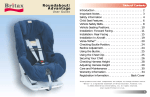
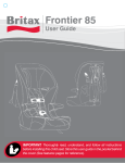
P2410_R01i.qxd
11/1/2004
10:51 AM
Page 1
Baby Safe
User Guide
P2410_R01i.qxd
11/1/2004
10:51 AM
Page 2
Table of Contents
Safety Information . . . . . . . . . . . . . . . . . . . . . . . . . . . . . . . . . . . . . . . . . . . . 2
WARNINGS . . . . . . . . . . . . . . . . . . . . . . . . . . . . . . . . . . . . . . . . . . . . . . . . 2
Important Notes . . . . . . . . . . . . . . . . . . . . . . . . . . . . . . . . . . . . . . . . . . . . 4
Certification. . . . . . . . . . . . . . . . . . . . . . . . . . . . . . . . . . . . . . . . . . . . . . . . 5
Registration . . . . . . . . . . . . . . . . . . . . . . . . . . . . . . . . . . . . . . . . . . . . . . . . 5
Features . . . . . . . . . . . . . . . . . . . . . . . . . . . . . . . . . . . . . . . . . . . . . . . . . . . . 6
Front View . . . . . . . . . . . . . . . . . . . . . . . . . . . . . . . . . . . . . . . . . . . . . . . . 6
Rear View . . . . . . . . . . . . . . . . . . . . . . . . . . . . . . . . . . . . . . . . . . . . . . . . . 7
Base . . . . . . . . . . . . . . . . . . . . . . . . . . . . . . . . . . . . . . . . . . . . . . . . . . . . . 7
Basic Carrier Functions . . . . . . . . . . . . . . . . . . . . . . . . . . . . . . . . . . . . . . . . . 8
Buckle . . . . . . . . . . . . . . . . . . . . . . . . . . . . . . . . . . . . . . . . . . . . . . . . . . . . 8
Harness . . . . . . . . . . . . . . . . . . . . . . . . . . . . . . . . . . . . . . . . . . . . . . . . . . . 9
Chest Clip . . . . . . . . . . . . . . . . . . . . . . . . . . . . . . . . . . . . . . . . . . . . . . . . 10
Handle . . . . . . . . . . . . . . . . . . . . . . . . . . . . . . . . . . . . . . . . . . . . . . . . . . 11
Canopy . . . . . . . . . . . . . . . . . . . . . . . . . . . . . . . . . . . . . . . . . . . . . . . . . . 11
Using the Carrier . . . . . . . . . . . . . . . . . . . . . . . . . . . . . . . . . . . . . . . . . . . . 12
Securing Child in Carrier. . . . . . . . . . . . . . . . . . . . . . . . . . . . . . . . . . . . . . 12
Checking Harness Height . . . . . . . . . . . . . . . . . . . . . . . . . . . . . . . . . . . . . 14
Harness Height Adjustment . . . . . . . . . . . . . . . . . . . . . . . . . . . . . . . . . . . 15
Vehicle Compatibility . . . . . . . . . . . . . . . . . . . . . . . . . . . . . . . . . . . . . . . . . 16
Vehicle Safety Belts . . . . . . . . . . . . . . . . . . . . . . . . . . . . . . . . . . . . . . . . . 16
Vehicle Seating Positions . . . . . . . . . . . . . . . . . . . . . . . . . . . . . . . . . . . . . 17
Basic Base Functions. . . . . . . . . . . . . . . . . . . . . . . . . . . . . . . . . . . . . . . . . . 18
ISOFIX Connectors. . . . . . . . . . . . . . . . . . . . . . . . . . . . . . . . . . . . . . . . . . 18
Protective Sleeve . . . . . . . . . . . . . . . . . . . . . . . . . . . . . . . . . . . . . . . . . . . 18
Recline Adjustment . . . . . . . . . . . . . . . . . . . . . . . . . . . . . . . . . . . . . . . . . 19
Vehicle Belt Installation Spacer . . . . . . . . . . . . . . . . . . . . . . . . . . . . . . . . . 19
Foot Prop . . . . . . . . . . . . . . . . . . . . . . . . . . . . . . . . . . . . . . . . . . . . . . . . 20
Using Carrier with Base . . . . . . . . . . . . . . . . . . . . . . . . . . . . . . . . . . . . . . 21
Base Installation . . . . . . . . . . . . . . . . . . . . . . . . . . . . . . . . . . . . . . . . . . . . . 22
ISOFIX Installation . . . . . . . . . . . . . . . . . . . . . . . . . . . . . . . . . . . . . . . . . . 22
Lap-Shoulder Belt Installation . . . . . . . . . . . . . . . . . . . . . . . . . . . . . . . . . . 24
Lap Belt Installation . . . . . . . . . . . . . . . . . . . . . . . . . . . . . . . . . . . . . . . . . 26
Carrier Only Installation . . . . . . . . . . . . . . . . . . . . . . . . . . . . . . . . . . . . . . . 28
Lap-Shoulder Belt Installation . . . . . . . . . . . . . . . . . . . . . . . . . . . . . . . . . . 28
Lap Belt Installation . . . . . . . . . . . . . . . . . . . . . . . . . . . . . . . . . . . . . . . . . 30
Aircraft Installation . . . . . . . . . . . . . . . . . . . . . . . . . . . . . . . . . . . . . . . . . . 31
Care and Maintenance . . . . . . . . . . . . . . . . . . . . . . . . . . . . . . . . . . . . . . . . 32
Warranty . . . . . . . . . . . . . . . . . . . . . . . . . . . . . . . . . . . . . . . . . . . . . . . . . . 36
This product and its components are subject to change without notice.
© 2 0 0 4 B r i t a x C h i l d S a f e t y, I n c . A l l r i g h t s r e s e r v e d . P r i n t e d i n U . S . A .
BB0-627-00 / P241000 R1:09/04
P2410_R01i.qxd
11/1/2004
10:51 AM
Page 4
• Use only in a rear facing position when using this restraint in
the vehicle. This infant restraint cannot be used forward facing
in a vehicle.
• Use only with children who weigh between 4 and 22 pounds
(2 and 10 kg) and whose height is 30 inches (76 cm) or less.
• Snugly adjust the belts provided with this restraint around your
child. A snug strap should not allow any slack. It lies in a
relatively straight line without sagging. It does not press on the
child’s flesh or push the child’s body into an unnatural position.
• Secure this child restraint with the vehicle’s child restraint
anchorage system if available or with a vehicle belt.
• Follow all instructions labeled on the child restraint and in these
written instructions.
• Secure this child restraint even when it is not occupied. In a
crash, an unsecured child restraint may injure vehicle
occupants.
• Consult your child’s doctor before using this child restraint.
Some infants must be secured with a device that allows them
to lie flat.
• The primary protection for occupants of a vehicle in a collision
is the structure of the vehicle itself; a child restraint will not
protect an infant when the vehicle is seriously impacted.
However, correctly installed, a child restraint will substantially
improve the chances for survival in most crashes. Make sure
that all users fully understand the correct ways to use this child
restraint in a vehicle.
• Always use foot prop when base is installed in vehicle! Foot prop
must be in Installation Mode for proper carrier attachment to base.
2
• Never use the adjuster strap to lift or carry this child restraint.
Doing so could cause damage to the harness adjuster and
webbing. Always carry a child restraint by the handle or shell.
• This child restraint must not be used in boats, or other
non-certified applications.
• NEVER leave child unattended.
• NEVER place carrier on beds, sofas, or other soft surfaces. Infant
carrier can roll over on soft surfaces and suffocate the child.
• NEVER use in or on strollers unless approved by Britax.
• NEVER install forward facing in a vehicle.
• NEVER place carrier near edges of counter tops, tables, or other
elevated surfaces. Child’s movement can slide carrier.
• NEVER leave child carrier when straps are loose or undone.
Child can strangle in loose restraint straps.
• Use of carrier in shopping carts can be dangerous.
• Watch your child closely when restraint is not installed in a
vehicle to avoid tipping over and strangulation.
• Harness must be used at all times when child is in carrier.
WARNING! DO NOT place a child
restraint in the front seat of a vehicle with
a passenger air bag unless the air bag is
turned off. DEATH or SERIOUS INJURY
can occur. The back seat is the safest
place for children under 12.
3
P2410_R01i.qxd
11/1/2004
10:51 AM
Page 6
Safety Information
Safety Information
Important Notes
• Verify that the child restraint is secure and that the harness is
properly adjusted around the child each time the child restraint
is used.
• Adjust the harness to fit the clothes the child is wearing. The fit for
a child in winter clothes will differ from a child in summer clothes.
• Cover the restraint when the vehicle is parked in direct sunlight.
Parts of the child restraint could become hot enough to burn
the child.
• Store the child restraint in a safe place when it is not being used
for an extended period of time. Do not place heavy objects on
top of it.
• Stop use of a child restraint that is older than six years or has
been in a severe crash to prevent injury due to deterioration or
hidden damage.
• Do not leave children alone in a vehicle, even for a short time.
• Do not, except as described in this booklet, attempt to
disassemble any part of the child restraint or change the way its
harness or the vehicle belts are used.
• Do not leave loose objects (e.g. books, bags, etc.) in the back of
a vehicle. In the event of a sudden stop, loose objects will keep
moving, potentially causing serious injuries.
• Do not leave folding vehicle seats unlatched. In the event of a
sudden stop, a loose seat back could prevent the child restraint
from protecting the child as well as it should.
• Do not allow children to play with the child restraint.
• Do not hang accessories or toys from handle. Doing so could
create a hazard for the child.
4
Weight Range
Rear Facing ONLY
4–22 lbs. (2–10 kg)
Maximum Height
The child is too tall when the top of the
head is above the top of the carrier or
height exceeds 30 inches (76 cm).
Certification
This child restraint system conforms to all applicable Federal motor
vehicle safety standards. This restraint is certified for use in motor
vehicles and aircraft.
Registration
Visit BritaxUSA.com to register your restraint online!
Child restraints could be recalled for safety reasons. You must
register this restraint to be reached in a recall. Send your name,
address, and the restraint's model number and manufacturing
date to Britax Child Safety, Inc. 13501 South Ridge Drive
Charlotte, NC 28273 or call 1-888-4BRITAX. For recall
information, call the U.S. Government's Auto Safety Hotline at
1-888-327-4236.
5
P2410_R01i.qxd
11/1/2004
10:52 AM
Page 8
Features
Features
1
2
27
28
3
4
5
6
7
8
9
10
14
5
15
16
17
18
13
19
20
21
22
23
24
10
25
29
11
12
13
1
2
3
4
5
6
7
6
Canopy
Handle
Cover
Head Support Pillow
Harness
Comfort Pad
Chest Clip
8
9
10
11
12
13
Buckle
Harness Adjuster Lever
Harness Adjuster Strap
Belly Pad
Belt Guide
Handle Release Button
14
15
16
17
18
19
20
21
22
Harness Slot
Anti-Rebound Bar
Lock-off Clip
Belt Guide
ISOFIX (LATCH) Connector
ISOFIX (LATCH) Release Button
Lock-off
Lock-off Release Tab
Carrier Release Button
26
23
24
25
26
27
28
29
Foot Prop Adjust Button
Yoke
Foot Prop
Attachment Rod
Vehicle Belt Installation Spacers
ISOFIX Guides
ISOFIX Protective Cap
7
P2410_R01i.qxd
11/1/2004
10:52 AM
Page 10
Basic Carrier Functions
Basic Carrier Functions
Buckle
Harness
To fasten buckle, fit the two buckle
tongues together (fig. A), then insert in
buckle (fig. B).
To loosen harness, press and hold harness
adjuster lever, while pulling harness straps
away from carrier. (fig. D).
To tighten harness, pull harness adjuster
strap away from carrier (fig. E).
IMPORTANT: Proper connection of the buckle
is confirmed with a positive click.
To unfasten buckle, press release button
until buckle tongues are ejected (fig. C).
A
D
IMPORTANT: Periodically clean buckle to
ensure safe operation. See Cleaning the
Buckle on page 33.
B
E
C
8
9
P2410_R01i.qxd
11/1/2004
10:52 AM
Page 12
Basic Carrier Functions
Basic Carrier Functions
Chest Clip
Handle
Secure the chest clip by sliding the harness
into the open slot (fig. A).
Adjust chest clip to the center of the child’s
chest, level with the armpits (fig. B).
Release the chest clip by sliding the
harness out of the open slot.
The handle is designed to be adjusted to
one of three positions: Sitting, In-Vehicle,
or Carrying (fig. C).
To adjust, press both handle release
buttons while rotating handle into desired
position.
A
Carrying
In-Vehicle
Sitting
IMPORTANT: Always adjust handle to In- C
Vehicle position while using in vehicle.
Canopy
To raise, pull canopy toward foot of carrier
(fig. D). To collapse, push canopy toward
head of carrier (fig. E).
B
D
E
10
11
P2410_R01i.qxd
11/1/2004
10:52 AM
Page 14
Using the Carrier
Using the Carrier
Securing Child in Carrier
1
2
3
4
5
6
7
8
9
Loosen harness completely (fig. A).
Release the chest clip.
Unfasten the buckle.
Move the harness straps to the sides of
the carrier.
Place child in the carrier.
A
Position the harness straps over child’s
shoulders.
Fasten buckle.
Secure chest clip (fig. B).
Gently pull up on the harness straps to
tighten the lap sections (fig. C).
B
10 Slowly pull the harness adjuster strap to
tighten harness for a snug fit (fig. D).
11 Position the chest clip at the center of
the child’s chest, level with the child’s
armpits. (fig. E).
12 Verify that harness is not twisted and all
connections are secure.
13 Verify that harness height is correct.
D
• Refer to Checking Harness Height on page
14 for instructions.
IMPORTANT:
• Check the harness tightness before each
use.
• If buckle or harness will not secure
properly, the buckle or adjuster may be
clogged with food, drink, or other material
that must be removed. See page 33 for
cleaning instructions.
E
C
12
13
P2410_R01i.qxd
11/1/2004
10:52 AM
Page 16
Using the Carrier
Using the Carrier
Checking Harness Height
Harness Height Adjustment
1 Place child in carrier, then secure
harness (see pages 12–13).
2 Observe where the harness is
positioned on the child’s shoulders.
1 Loosen harness completely.
2 From the rear of the carrier, unhook the
harness straps from the yoke (fig. A).
3 Lean head support pillow forward,
then pull straps through the shell and
cover.
• Harness straps must be located at or
slightly below the child’s shoulders.
3 If harness height is correct, continue
using child carrier without adjustment.
If harness height requires adjustment,
refer to Harness Height Adjustment on
page 15.
Rear Facing
Strap Height
• It is not necessary to pull straps through A
slots in the head support pillow.
4 Thread the harness straps through
slots cover and shell, at the new
height (fig. B).
5 Reattach harness straps to the
yoke (fig. C).
6 Pull harness adjuster strap to tighten
the harness.
7 Verify that all straps are threaded at the B
same height and are not twisted.
C
14
15
P2410_R01i.qxd
11/1/2004
10:52 AM
Page 18
Vehicle Compatibility
Vehicle Compatibility
Vehicle Safety Belts
Vehicle Seating Positions
IMPORTANT:
WARNING:
• The information in this section only applies to installation with vehicle
safety belts.
• Some vehicles do not have seating positions which are compatible with
this child restraint. If in doubt, contact the vehicle manufacturer.
This child restraint can fit securely in most vehicles using the existing vehicle
belts. However, some vehicle designs prevent a secure fit of the child restraint
due to the position of the vehicle belt lower anchorage points.
The owner's manual for your vehicle will
have information on the types of vehicle
belts in your vehicle. If your belt type is
listed below, select another seating position
or use ISOFIX connectors.
The following types of vehicle belts are not
compatible with this child restraint:
Front vehicle belts with top or bottom
anchorage points in the door.
Motor driven automatic vehicle belts.
Three-point belts that have separate
retractors for the shoulder section and
the lap section.
2-point Emergency Locking Retractor
(ELR) vehicle belts without the use of a
belt shortening clip.
16
• Forward facing vehicle seats MUST be used with this child carrier. Side
facing or rear facing vehicle seats CANNOT be used.
• DO NOT place a child carrier in the front seat of a vehicle with a
passenger air bag, unless the air bag is turned off. DEATH or SERIOUS
INJURY can occur. The back seat is the safest place for children under 12.
17
P2410_R01i.qxd
11/1/2004
10:52 AM
Page 20
Basic Base Functions
Basic Base Functions
ISOFIX Connectors
Vehicle Belt Installation Spacers
The ISOFIX connectors should be in either
ISOFIX Installation Mode (fig. A) or Vehicle
Belt Installation Mode (fig. B).
Due to varying locations of vehicle belt
anchor points, the Vehicle Belt Installation
Spacers must be used for a secure vehicle
belt installation.
To use spacers, insert one spacer on each
side of anti-rebound bar (fig. C) before
installing base with a vehicle belt.
C
A
IMPORTANT: Spacers must be removed for
ISOFIX installation.
Recline Adjustment
To adjust recline level, press both tabs
while moving the recline block up (fig. D)
or down (fig. E), to desired location.
B
ISOFIX Protective Cap
The ISOFIX Protective Cap must be used
when base is installed using vehicle belts.
To attach Protective Cap, align with
connectors as shown, then press until
positive click is heard (fig. C).
To remove Protective Cap, squeeze green
and red ISOFIX release buttons, then pull
cap off.
C
18
IMPORTANT: Use level line indicator on
carrier to assist with achieving correct
recline angle.
D
If further recline adjustment is necessary,
use a tightly rolled towel.
WARNING: Only raise carrier as described
above. Do not raise the carrier off of the
front edge of the vehicle seat; doing so will
reduce the protection for your child.
E
19
P2410_R01i.qxd
11/1/2004
10:52 AM
Page 22
Basic Base Functions
Basic Base Functions
Foot Prop
Using Carrier with Base
To use foot prop, press release button and
compress foot prop, then swing foot prop
up from base, into Installation Mode
(fig. A).
To attach, line up carrier with base, rear
facing, then push down until positive click
confirms correct attachment (fig. D).
Check installation by lifting carrier from
both ends to verify that both attachment
rods are engaged with the base. Visual
confirmation can be made, using the
button indicator on the rear of the base D
(fig. E).
WARNING:
• Always use foot prop when base is
installed in vehicle! Foot prop must be in
Installation Mode for proper carrier A
attachment to base.
• Never use foot prop to raise base above
vehicle seat surface. Doing so will reduce
the stability of the base.
WARNING: Carrier must be attached properly
to the base. When carrier is attached
properly, the green indicator band on the
release button is fully visible (fig. E).
Adjust foot prop height by pressing Foot
Prop Adjust Button while sliding foot prop
to the shortest position that provides
contact with the vehicle floor (fig. B).
To store foot prop for transport outside of
the vehicle, adjust to shortest position, then B
collapse into Storage Mode (fig. C). Press
tab into slot on bottom of base to secure.
To release, press release button on base,
then lift carrier to remove (fig. F).
IMPORTANT: Always adjust handle to InVehicle position while using in a vehicle.
E
Indicator
1
2
C
20
E
21
P2410_R01i.qxd
11/1/2004
10:53 AM
Page 24
Base Installation
Base Installation
5 Adjust foot prop so that it is against the
vehicle floor.
ISOFIX Installation
• Figure A illustrates a typical base ISOFIX
installation.
• Remove carrier before installing base.
• Verify that your vehicle is equipped with
ISOFIX anchors. If ISOFIX anchors are not
available, you must use vehicle belt
installation methods.
WARNING: Never use foot prop to raise base
above vehicle seat surface. Doing so will
reduce the stability of the base.
6 Attach carrier to base.
1 Place ISOFIX connectors in ISOFIX A
Installation Mode.
• Remove ISOFIX Protective Cap and
spacers, if installed.
2 Place foot prop in Installation Mode.
• Always use foot prop when base is
3 Line up ISOFIX connectors on base
with anchors in vehicle (fig. B).
Removal
• If it is difficult to line up ISOFIX
connectors with ISOFIX anchors, use
Insertion Aid for assistance, as instructed B
on page 23.
4 Engage ISOFIX connectors by pressing
base onto ISOFIX anchors, until a
positive click is heard (fig. C).
22
Indicator
7 Adjust carrier handle to In-Vehicle
position.
installed in vehicle!
• Visual confirmation can be made using
the green ISOFIX indicators. Green
indicator must be fully visible from the
side when installed properly (fig. D).
• Pull base away from vehicle seat to further
verify attachment.
• Verify that the green indicator band on
the release button is fully visible.
• Verify that the red line on carrier is level D
with the ground.
• If angle is not correct, remove carrier and
base, then adjust recline angle as directed
on page 19.
Squeeze green and red ISOFIX release
buttons on each connector (fig. D), then
D
pull base away from vehicle seat.
IMPORTANT: Always store ISOFIX connectors
when not in use. See page 18.
ISOFIX Guides
C
If necessary, use ISOFIX Guides to assist
with base attachment to ISOFIX anchors.
To use, clip ISOFIX Guide onto each
ISOFIX connector that will be used for
installation of base (Fig. E).
ISOFIX Guide
E
23
P2410_R01i.qxd
11/1/2004
10:53 AM
Page 26
Base Installation
Base Installation
Lap-Shoulder Belt Installation
• Figure A illustrates a typical base lapshoulder belt installation.
• Remove carrier before installing base.
1 Insert Vehicle Belt Installation Spacers
and ISOFIX Protective Cap (pgs. 18-19).
2 Place foot prop in Installation Mode.
• Always use foot prop when base is
installed in vehicle!
A
3 Place the base on the vehicle seat with
the anti-rebound bar against the
vehicle seat back and ISOFIX
connectors in Vehicle Belt Installation
Mode.
4 Place the ISOFIX Connectors, with
protective cap installed, in the seat
bight (where the seat back and seat
cushion meet).
B
5 Open lock-off by sliding clip out, then
lifting release tab (fig. B).
6 With shoulder and lap portion of
vehicle seat belt together, slide under
both belt guides (fig. C).
7 Verify that the vehicle belt is not
twisted, then buckle (fig. D).
C
24
8 Press the base firmly into the seat while
removing slack from the lap portion of
the vehicle belt, then the shoulder
portion (fig. E).
9 Close the lock-off over the vehicle belt
(fig. F), then slide clip in to secure.
10 Verify that vehicle belt is tight and that
the base is stable.
D
• Base is tight when it cannot be moved
more than 1” (2.5 cm) at the belt path.
11 Adjust foot prop so that it is against the
vehicle floor.
WARNING: Never use foot prop to raise base
above vehicle seat surface. Doing so will
reduce the stability of the base.
12 Attach carrier to base.
• Verify that the green indicator band on
the release button is fully visible.
E
• Verify that the red line on carrier is level
with the ground.
• If angle is not correct, remove carrier and
base, then adjust recline angle as directed
on page 19.
13 Adjust carrier handle to In-Vehicle
position.
Removal
Unbuckle vehicle belt, then open lock-off
and remove vehicle belt from belt guides.
F
25
P2410_R01i.qxd
11/1/2004
10:53 AM
Page 28
Base Installation
Base Installation
8 Press the base firmly into the seat while
removing slack from the vehicle belt,
(fig. E).
9 Close the lock-off over the vehicle belt
(fig. F), then slide clip in to secure.
10 Verify that vehicle belt is tight and that
the base is stable.
Lap Belt Installation
• Figure A illustrates a typical base lap belt
only installation.
• Remove carrier before installing base.
1 Insert Vehicle Belt Installation Spacers
and ISOFIX Protective Cap (pgs. 18-19).
2 Place foot prop in Installation Mode.
• Always use foot prop when base is
installed in vehicle!
A
3 Place the base on the vehicle seat with
the anti-rebound bar against the
vehicle seat back and ISOFIX
connectors in Vehicle Belt Installation
Mode.
4 Place the ISOFIX Connectors, with
protective cap installed, in the seat
bight (where the seat back and seat
cushion meet).
B
5 Open lock-off by sliding clip out, then
lifting release tab (fig. B).
6 Slide vehicle belt under both belt
guides (fig. C).
7 Verify that the vehicle belt is not
twisted, then buckle (fig. D).
• Base is tight when it cannot be moved
D
more than 1” (2.5 cm) at the belt path.
11 Adjust foot prop so that it is against the
vehicle floor.
WARNING: Never use foot prop to raise base
above vehicle seat surface. Doing so will
reduce the stability of the base.
12 Attach carrier to base.
• Verify that the green indicator band on
the release button is fully visible.
• Verify that the red line on carrier is level
E
with the ground.
• If angle is not correct, remove carrier and
base, then adjust recline angle as directed
on page 19.
13 Adjust carrier handle to In-Vehicle
position.
Removal
Unbuckle vehicle belt, then open lock-off
and remove vehicle belt from belt guides
C
26
F
27
P2410_R01i.qxd
11/1/2004
10:53 AM
Page 30
Carrier Only Installation
Carrier Only Installation
Lap-Shoulder Belt Installation
• Figure A illustrates a typical rear facing
lap-shoulder belt installation of carrier
only.
WARNING: Do not install this carrier using a
non-locking ELR vehicle belt, unless a
locking clip is used. Refer to the vehicle
owner’s manual for instructions on correct
A
use of vehicle belts with child carriers.
1 Place the carrier rear facing on the
vehicle seat.
2 With shoulder and lap portion of
vehicle seat belt together, route
through both belt guides (fig. B).
3 Verify that the vehicle belt is not
twisted, then buckle (fig. C).
WARNING: Only raise carrier as described
above. Do not raise the carrier off of the B
front edge of the vehicle seat; doing so will
reduce the protection for your child.
4 Push the carrier firmly into the vehicle
seat while removing slack from the lap
portion of the vehicle belt, then the
shoulder portion (fig. D).
5 Verify that vehicle belt is tight and that
the carrier is stable.
• Base is tight when it cannot be moved
more than 1” (2.5 cm) at the belt path
• Verify that the red line on carrier is level D
with the ground.
• If angle is not correct, loosen vehicle belt
and adjust recline angle.
• If there is a problem stabilizing the carrier
or achieving necessary angle, place a
tightly rolled towel in the crease of the
vehicle seat to help level the carrier.
6 Adjust carrier handle to In-Vehicle
position.
C
28
29
P2410_R01i.qxd
11/1/2004
10:53 AM
Page 32
Carrier Only Installation
Carrier Only Installation
5 Adjust carrier handle to In-Vehicle
position.
6 Verify that vehicle belt is tight and that
the carrier is stable.
Lap Belt Installation
• Figure A illustrates a typical rear facing lap
belt installation of carrier only.
WARNING: Do not install this carrier using a
non-locking ELR vehicle belt, unless a belt
shortening clip is used. Refer to the vehicle
owner’s manual for instructions on correct
use of vehicle belts with child carriers.
1 Place the carrier rear facing on the A
vehicle seat.
2 Route vehicle belt through both belt
guides (fig. B).
3 Verify that the vehicle belt is not
twisted, then buckle (fig. C).
• When correctly reclined, the red line on
carrier will be level with the ground.
• If there is a problem stabilizing the carrier,
place a rolled towel in the crease of the
B
vehicle seat to help level the carrier.
WARNING: Only raise carrier as described
above. Do not raise the carrier off of the
front edge of the vehicle seat; doing so will
reduce the protection for your child.
4 Push the carrier firmly into the vehicle
seat while removing slack from the
vehicle belt (fig. D).
C
30
• Base is tight when it cannot be moved
more than 1” (2.5 cm) at the belt path
• Verify that the red line on carrier is level
with the ground.
• If angle is not correct, loosen vehicle belt D
and adjust recline angle.
• If there is a problem stabilizing the carrier
or achieving necessary angle, place a
tightly rolled towel in the crease of the
vehicle seat to help level the carrier.
Aircraft Installation
This child carrier is certified for use in
aircraft. Most airlines in the U.S. and
Canada will allow the use of a child
carrier if it is labeled as an approved child
carrier for airline use and fits properly on
the aircraft. Contact the airline about
their policy prior to traveling.
To install in aircraft, follow instructions
for Carrier Only Lap Belt Installation on
page 30.
• Place the carrier next to a window to
avoid blocking the aisle.
• If the aircraft belt is too short, ask the
flight attendant for a Belt Extender.
31
P2410_R01i.qxd
11/1/2004
10:53 AM
Page 34
Care and Maintenance
Care and Maintenance
Buckle Removal
Cleaning the Buckle
1 From the bottom of the carrier,
locate metal buckle strap
retainer.
2 Pull retainer away from carrier
to loosen.
3 Turn the retainer so that the
short side will go through the A
slot in the carrier shell to the
opposite side of the carrier (fig. A).
4 Thread the retainer through the hole in
cover to remove buckle from carrier.
If a child eats and drinks while in the
carrier, the buckle may need to be
periodically checked and cleaned of any
accumulated debris or dried liquids.
• THOROUGHLY RINSE,
using warm water (fig. C).
• SOAK, overnight if possible, using
warm water to loosen hardened C
drinks or food.
• TEST THE BUCKLE, by fastening and unfastening until a
positive click is heard. If a click is not heard, repeat cleaning
procedure.
• TOWEL DRY
• DO NOT: Lubricate, use solvents, abrasive cleaners, soap or
household detergents.
Buckle Installation
1 Turn the buckle retainer (fig. B) so
that the short side will go through the
slot in the cover and carrier shell.
2 Pull buckle away from carrier until B Buckle Retainer
tight, then verify that the strap is not
twisted and the release button is facing outward.
IMPORTANT: Verify that retainer is threaded through both the cover AND
the shell.
32
33
P2410_R01i.qxd
11/1/2004
10:53 AM
Page 36
Care and Maintenance
Care and Maintenance
Cover Removal
1 Unhook attachment loops.
2 Loosen harness completely.
3 From the bottom of the carrier, unhook both harness straps from
the yoke.
4 From the top of the carrier, pull each harness strap through the
upper harness slot, head support pillow and cover slot to the top
of the carrier.
5 Unfasten buckle.
6 Pull the harness straps, buckle tongues, and chest clip through the
slots in the cover.
7 Remove buckle and belly pad.
8 Remove cover and head support pillow from the carrier.
WARNING:
• Do not take harness apart or completely remove from carrier. It is
unnecessary and dangerous to do so.
• Never remove the buckle tongues from the harness. They cannot be
reattached after removal.
Refitting the Cover
Cleaning the Cover, Belly pad & Head Support Pillow
• HAND WASH, using cold water and mild soap.
• LINE DRY, to prevent shrinkage.
• DO NOT: Bleach, machine wash, machine dry, or iron.
Cleaning the Shell & Harness
• BRUSH AWAY LOOSE DEBRIS, using a soft bristled brush.
• SPONGE CLEAN, using warm water and mild soap.
• TOWEL DRY
• DO NOT: Use solvents, abrasive cleaners, or bleach. Do not
machine wash, machine dry, or disassemble the harness.
Cleaning the Harness Adjuster
WARNING: Periodically check the adjuster area to be sure it is clean and free
of food, coins, dirt, and other objects. If debris is present, it must be
removed to prevent interference with the adjuster mechanism.
• BRUSH AWAY LOOSE DEBRIS, using a soft bristled brush.
• SPONGE CLEAN, using warm water and mild soap.
• TOWEL DRY
• DO NOT: Use solvents, abrasive cleaners, or disassemble the
harness.
To refit the cover, reverse Cover Removal directions. Make sure that
the harness is not twisted.
34
35
P2410_R01i.qxd
11/1/2004
10:53 AM
Page 38
Warranty
This child restraint was manufactured by Britax. Britax Child Safety, Inc. (“Britax”)
warrants this product to the original retail purchaser as follows:
LIMITED ONE-YEAR WARRANTY
This product is warranted against defective materials or workmanship for one year from
the date of original purchase. Proof of purchase is required. The exclusive remedy for this
warranty is that Britax will, at its option, provide repair or replacement components for
this product or refund the original purchase price of the product. Britax reserves the right
to discontinue or change fabrics, parts, models or products, or to make substitutions.
To make a claim under this warranty, contact Britax Consumer Services at
1-888-427-4829 or write to us using the address on the back cover of this booklet. Proof
of purchase is required.
PLEASE COMPLETE AND MAIL THE OWNER REGISTRATION CARD WITHIN (30) DAYS
OF PURCHASE.
WARRANTY LIMITATIONS
This warranty does not include damages which arise from negligence, misuse or use not
in accordance with the product instruction.
The use of non-Britax Child Safety, Inc. covers, inserts, toys, accessories, or tightening
devices is not approved by Britax. Their use could cause this restraint to fail Federal Safety
Standards or perform worse in a crash. Their use automatically voids the Britax warranty.
LIMITATION OF DAMAGES
The warranty and remedies as set forth above are exclusive and in lieu of all others, oral
or written, express or implied. In no event will Britax, or the retailer selling this product,
be liable for any damages, including incidental or consequential damages, arising out of
the use or inability to use this product.
LIMITATIONS OF WARRANTIES AND OTHER WARRANTY TERMS AND
STATE LAWS
Any implied warranties, including implied warranties of merchantability and fitness for a
particular purpose, shall be limited to the duration and terms of the express written
warranty. Some states do not allow limitations on how long an implied warranty lasts or
the exclusion or limitation of incidental or consequential damages, so the above limitations may not apply. This warranty gives you specific legal rights, and you may have other
rights, which vary from state to state. Neither Britax, nor the retailer selling this product,
authorizes any person to create for it any other warranty, obligation, or liability in
connection with this product.
36
P2410_R01i.qxd
11/1/2004
10:54 AM
Page 40