1
AOC 210V User Manual
Preface
About This Guide
This guide describes the monitor's features, setup, and operation. lnformation in this document is subject to change without notice.
The sections are as follows:
x
Safety Instructions: lists safety information.
x
Setup: describes the initial setup process.
x
Using the Monitor: gives an overview of how to use the monitor.
x
Drivers: provides driver installation instructions for Windows.
x
Technical Support :provides tips and solutions for common problems.
x
Product Information: lists the technical specifications of the monitor.
x
Warranty Statement: Warranty Statement used in Australia and New Zealand.
National Conventions
The following subsections describe notational conventions used in this document.
Notes, Cautions, and Warnings
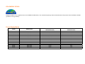
Throughout this guide, blocks of text may be accompanied by an icon and printed in bold type or in italic type. These blocks are notes, cautions, and warnings, and they are used as
follows:
NOTE: A NOTE indicates important information that helps you make better use of your computer system.
CAUTION: A CAUTION indicates either potential damage to hardware or loss of data and tells you how to avoid the problem.
WARNING: A WARNING indicates the potential for bodily harm and tells you how to avoid the problem.
Some warnings may appear in alternate formats and may be unaccompanied by an icon. In such cases, the specific presentation of the warning is mandated by regulatory authority
Safety Instructions
FCC Notice
FCC Class B Radio Frequency Interference Statement WARNING: (FOR FCC CERTIFIED MODELS)
NOTE: This equipment has been tested and found to comply with the limits for a Class B digital device, pursuant to Part 15 of the FCC Rules. These limits are designed to provide
reasonable protection against harmful interference in a residential installation. This equipment generates, uses and can radiate radio frequency energy, and if not installed and used in
accordance with the instructions, may cause harmful interference to radio communications. However, there is no guarantee that interference will not occur in a particular installation. If
this equipment does cause harmful interference to radio or television reception, which can be determined by turning the equipment off and on, the user is encouraged to try to correct the
interference by one or more of the following measures:
1.
Reorient or relocate the receiving antenna.
2.
Increase the separation between the equipment and receiver.
3.
Connect the equipment into an outlet on a circuit different from that to which the receiver is connected.
4.
Consult the dealer or an experienced radio/TV technician for help.
NOTICE :
1.
The changes or modifications not expressly approved by the party responsible for compliance could void the user's authority to operate the equipment.
2.
Shielded interface cables and AC power cord, if any, must be used in order to comply with the emission limits.
3.
The manufacturer is not responsible for any radio or TV interference caused by unauthorized modification to this equipment. It is the responsibilities of the user to correct such
interference.
WEEE Declaration
Disposal of Waste Equipment by Users in Private Household in the European Union.
This symbol on the product or on its packaging indicates that this product must not be disposed of with your other household waste. Instead, it is your responsibility to dispose of your
waste equipment by handing it over to a designated collection point for the recycling of waste electrical and electronic equipment. The separate collection and recycling of your waste
equipment at the time of disposal will help to conserve natural resources and ensure that it is recycled in a manner that protects human health and the environment. For more
information about where you can drop off your waste equipment for recycling, please contact your local city office, your household waste disposal service or the shop where you
purchased the product.
HG Declaration
SAFETY: Lamp Disposal
LAMP(S) INSIDE THIS PRODUCT CONTAIN MERCURY AND MUST BE RECYCLED OR DISPOSED OF ACCORDING TO LOCAL, STATE OR FEDERAL LAWS. FOR MORE
INFORMATION, CONTACT THE ELECTRONIC INDUSTRIES ALLIANCE AT WWW.EIAE.ORG.
Precautions
WARNING: Use of controls, adjustments, or procedures other than those specified in this documentation may result in exposure to shock, electrical hazards, and/or
mechanical hazards.
Read and follow these precautions when connecting and using your computer monitor:
PRECAUTIONS
x
Do not use the monitor near water, e.g. near a bathtub, washbowl, kitchen sink, laundry tub, swimming pool or in a wet basement.
x
Do not place the monitor on an unstable cart, stand, or table. If the monitor falls, it can injure a person and cause serious damage to the appliance. Use only a cart or stand
recommended by the manufacturer or sold with the monitor. If you mount the monitor on a wall or shelf, use a mounting kit approved by the manufacturer and follow the kit
instructions.
x
Slots and openings in the back and bottom of the cabinet are provided for ventilation. To ensure reliable operation of the monitor and to protect it from overheating, be sure
these openings are not blocked or covered. Do not place the monitor on a bed, sofa, rug, or similar surface. Do not place the monitor near or over a radiator or heat register. Do
not place the monitor in a bookcase or cabinet unless proper ventilation is provided.
x
The monitor should be operated only from the type of power source indicated on the label. If you are not sure of the type of power supplied to your home, consult your dealer or
local power company.
x
The monitor is equipped with a three-pronged grounded plug, a plug with a third (grounding) pin. This plug will fit only into a grounded power outlet as a safety feature. If your
outlet does not accommodate the three-wire plug, have an electrician install the correct outlet, or use an adapter to ground the appliance safely. Do not defeat the safety
purpose of the grounded plug.
x
Unplug the unit during a lightning storm or when it will not be used for long periods of time. This will protect the monitor from damage due to power surges.
x
Do not overload power strips and extension cords. Overloading can result in fire or electric shock.
x
Never push any object into the slot on the monitor cabinet. It could short circuit parts causing a fire or electric shock. Never spill liquids on the monitor.
x
Do not attempt to service the monitor yourself; opening or removing covers can expose you to dangerous voltages and other hazards. Please refer all servicing to qualified
service personnel.
x
To ensure satisfactory operation, use the monitor only with UL listed computers which have appropriate configured receptacles marked between 100 - 240V AC, Min. 5A.
x
The wall socket shall be installed near the equipment and shall be easily accessible.
x
For use only with the attached power adapter (Output 12Vdc) which have UL,CSA listed license(Only for monitors with power adapter).
Setup
Setup the stand and base
Please setup or remove the base following below steps.
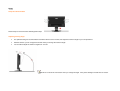
Adjusting Viewing Angle
x
For optimal viewing it is recommended to look at the full face of the monitor, then adjust the monitor's angle to your own preference.
x
Hold the stand so you do not topple the monitor when you change the monitor's angle.
x
You are able to adjust the monitor's angle from -5°to 20°.
NOTE: Do not touch the LCD screen when you change the angle. It may cause damage or break the LCD screen.
Attaching the Cables
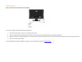
Cable Connections On Back of Monitor and Computer
1.Power
2.DVI
3.Analog
Turn off your computer before performing the procedure below.
1.
Connect the power cable to the AC port on the back of the monitor.
2.
Connect one end of the 15-pin D-Sub cable to the back of the monitor and connect the other end to the computer's D-Sub port.
3.
(Optional - Requires a video card with DVI port) - Connect one end of the 24-pin DVI cable to the back of the monitor and connect the other end to the computer's DVI port
4.
Turn on your monitor and computer.
If your monitor displays an image, installation is complete. If it does not display an image, see Troubleshooting.
Attaching Wall Mounting Arm
Preparing to Install An Optional Wall Mounting Arm
This monitor can be attached to a wall mounting arm you purchase separately. Disconnect power before this procedure. Follow these steps:
1.
Remove the base.
2.
Follow the manufacturer's instructions to assemble the wall mounting arm.
3.
Place the wall mounting arm onto the back of the monitor. Line up the holes of the arm with the holes in the back of the monitor.
4.
Insert the 4 screws into the holes and tighten.
5.
Reconnect the cables. Refer to the user's manual that came with the optional wall mounting arm for instructions on attaching it to the wall.
Using the Monitor
Setting the Optimal Resolution
The recommended resolution for this monitor is 1680 by 1050. To setup the monitor to this resolution, follow the steps below.
1.
Click START.
2.
Click SETTINGS.
3.
Click CONTROL PANEL.
4.
Double click DISPLAY.
5.
Click SETTINGS.
6.
Set the resolution SLIDE-BAR to 1680 by 1050.
External Controls
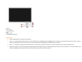
Press the power button to turn the monitor on or off. The other control knobs are located at front panel of the monitor (See Figure ). By changing these settings, the picture can be
adjusted to your personal preferences.
* The power cord should be connected.
* Press the power button to turn on the monitor. The power indicator will light up.
1.Souce
2. Auto Config
3. Eco Mode/ down
4. Up
5. Menu / Enter
6. Power Button & Indicator
OSD Settings
x
Press the MENU-button to activate the OSD window.
x
Press+ or - to navigate through the functions. Once the desired function is highlighted, press the MENU-button to activate it. If the function selected has a sub-menu, press or
again to navigate through the sub-menu functions. Once the desired function is highlighted, press MENU-button to activate it.
x
Press+ or - to change the settings of the selected function. To exit and save, select the exit function. If you want to adjust any other function, repeat steps 2-3.
x
OSD Lock Function: To lock the OSD, press and hold the MENU button while the monitor is off and then press power button to turn the monitor on. To un-lock the OSD - press
and hold the MENU button while the monitor is off and then press power button to turn the monitor on.
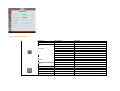
Function Control Illustration
Luminance
Brightness
Contrast
Eco mode
Gamma
DCR
Image Setup
Clock
Focus
H.Position
V.Position
Adjust Range
0-100
0-100
Standard
Text
Internet
Game
Movie
Sports
Gamma1
Gamma2
Gamma3
Off
On
Description
Backlight Adjustment
Contrast from Digital-register.
Standard Mode
Text Mode
Internet Mode
Game Mode
Movie Mode
Sports Mode
Adjust to Gamma1
Adjust to Gamma 2
Adjust to Gamma 3
Disable dynamic contrast ratio
Enable dynamic contrast ratio
0-100
0-100
0-100
0-100
Adjust picture Clock to reduce Vertical-Line noise.
Adjust Picture Phase to reduce Horizontal-Line noise
Adjust the vertical position of the picture.
Adjust the horizontal position of the picture.
Color Temp.
Warm
Normal
Cool
sRGB
User
Color Boost
Full Enhance
Nature Skin
Green Field
Sky-blue
AutoDetect
Demo
Picture Boost
Frame Size
Brightness
Contrast
Hue
Saturation
Position
Bright Frame
OSD Setup
H.Position
V.Position
Timeout
Language
Extra
Input Select
Auto Config
Reset
DDC-CI
Information
User-B
User-G
User-R
User-Y
User-C
User-M
Recall Warm Color Temperature from EEPROM.
Recall Normal Color Temperature from EEPROM.
Recall Cool Color Temperature from EEPROM.
Recall SRGB Color Temperature from EEPROM.
Blue Gain from Digital-register
Green Gain Digital-register.
Red Gain from Digital-register
Yellow Gain from Digital-register
Cyan Gain from Digital-register
Magenta Gain from Digital-register
on or off
on or off
on or off
on or off
on or off
on or off
Disable or Enable Full Enhance Mode
Disable or Enable Nature Skin Mode
Disable or Enable Green Field Mode
Disable or Enable Sky-blue Mode
Disable or Enable AutoDetect Mode
Disable or Enable Demo
0-100
0-100
0-100
0-100
0-100
H. position
V.position
on or off
Adjust Frame Size
Adjust Frame Brightness
Adjust Frame Contrast
Adjust Frame Hue
Adjust Frame Saturation
Adjust Frame horizontal Position
Adjust Frame vertical Position
Disable or Enable Bright Frame
0-100
0-100
0-100
Adjust the vertical position of OSD
Adjust the horizontal position of OSD
Adjust the OSD Timeout
Select the OSD language
Digital
Analog
yes or no
yes or no
Select Digital Signal Source as Input
Select Analog Signal Source as Input
Auto adjust the picture to default
Reset the menu to default
Turn ON/OFF DDC-CI Support
Show the information of the main image and
sub-image source
LED Indicators
Status
LED Color
Full Power Mode
Green
Active-off Mode
Orange
Driver
Windows ME &2000
1.
2.
3.
4.
5.
6.
7.
8.
9.
10.
11.
12.
13.
14.
15.
16.
17.
18.
19.
Click START.
Click SETTINGS.
Select CONTROL PANEL.
From the CONTROL PANEL, double click the DISPLAY icon.
From the Display Properties Window, select the SETTINGS tab.
Click ADVANCED.
Click MONITOR.
Click PROPERTIES.
Click DRIVER.
Click UPDATE DRIVER.
Click NEXT.
Select "DISPLAY a list ......".
Select HAVE DISK.
Click Browse, Select "Driver" folder , choose the model you want to install (where "D" is the driver letter of your CD ROM drive)
Click NEXT.
Click FINISH.
Click CLOSE.
Click OK.
Click OK.
Windows XP
1. "Right Click" the mouse anywhere on the "BLANK" area on the desktop and click on PROPERTIES.
2. Click the SETTINGS tab and then click ADVANCED.
3. Click the MONITOR tab and then click PROPERTIES.
4. Under MONITOR PROPERTIES, click DRIVER then click UPDATE DRIVER.
5. On the HARDWARE UPDATE WIZARD, select Install from a list of specific location (ADVANCED) then click Next.
6. On the next HARDWARE UPDATE WIZARD window, select DON'T SEARCH, I WILL CHOOSE THE DRIVER TO INSTALL. Then click NEXT.
7. On the following window, click on HAVE DISK.
8. Click Browse, Select" Driver" folder , choose the model you want to install
9. Note: If Windows prompts you that the driver is not signed, click CONTINUE ANYWAY.
10. On the last window of HARDWARE UPDATE WIZARD click FINISH to complete the installation.
11. After the monitor driver installation has been done, restart the computer to update the windows setup for driver installation.
Windows Vista
1. Select Start->Control panel, then double click Hardware and Sound and enter Display Properties.
2. Click Personalization.
3. Click Display Settings.
4. Click Advanced Settings.
5. Click Monitor.
6. Click Properties.
7. Click Driver.
8. Select Update Driver then click Update Driver Software-Generic PnP Monitor. Click Browse my computer for driver software.
9. Select Let me pick from a list of device drivers on my computer.
10. Click Have Disk .Click Browse ,Select driver file on the disk:
D:\ Drivers\model name (where "D" is the driver letter of your CD ROM drive)
11. select .inf file then click Open,then click OK .
12. Note: If Windows prompts you that the driver is not signed, click CONTINUE ANYWAY.
13. After the monitor driver installation has been done, restart the computer to update the windows setup for driver installation.
Technical Support
Frequently Asked Questions
Problem & Question
Power LED Is Not ON
Possible Solutions
x
the monitor.
x
Problem
Picture Bounces, Flickers Or Wave Pattern Is
Present In The Picture
Monitor Is Stuck In Active Off-Mode"
In order for the Plug & Play feature of the monitor to work, you need a Plug & Play compatible computer & video
card. Check with your computer manufacturer. Also check the monitor's video cable and make sure none of the
No Plug & Play
Picture Is Fuzzy & Has Ghosting Shadowing
Make sure the power button is ON and the Power Cord is properly connected to a grounded power outlet and to
pins are bent.
x
Make sure the AOC Monitor Drivers are installed (AOC Monitor Drivers are available at : http://www.aoc.com)
x
x
Adjust the Contrast and Brightness Controls.
Make sure you are not using an extension cable or switch box. We recommend plugging the monitor directly to
the video card output connector on the back of your computer.
x
x
Move electrical devices that may cause electrical interference as far away from the monitor as possible.
x
x
x
x
x
The Computer Power Switch should be in the ON position.
Use the maximum refresh rate your monitor is capable of at the resolution your are using.
The Computer Video Card should be snugly seated in its slot.
Make sure the monitor's video cable is properly connected to the computer.
Inspect the monitor's video cable and make sure none of the pins are bent.
Make sure your computer is operational by hitting the CAPS LOCK key on the keyboard while observing the
CAPS LOCK LED. The LED should either turn ON or OFF after hitting the CAPS LOCK key.
x
x
Inspect the monitor's video cable and make sure that none of the pins are bent.
or BLUE)
Screen image is not centered or sized properly
x
Adjust H-Position and V-Position or press hot-key (AUTO).
Picture has color defects (white does not look
x
Adjust RGB color or select color temperature
x
Use win 95/98 shut-down mode Adjust CLOCK and FOCUS or perform hot-key (AUTO-key )
Missing one of the primary colors (RED, GREEN,
white)
Horizontal or vertical disturbances on the
screen
Make sure the monitor's video cable is properly connected to the computer.
Product Information
LCD Panel
Resolution
Model number
Driving system
Size
Pixel pitch
Video
Separate Sync.
Display Color
Dot Clock
Horizontal scan range
Horizontal scan Size(Maximum)
Vertical scan range
Vertical scan Size(Maximum)
Optimal preset resolution
Highest preset resolution
Plug & Play
Input Connector
Input Video Signal
Power Source
Power Consumption
Physical Characteristics
Environmental
Regulations
Connector Type
Signal Cable Type
Dimensions & Weight:
Height (with base)
Width
Depth
Weight (monitor only)
Weight (with packaging)
Temperature:
Operating
Non-Operating
Humidity:
Operating
Non-Operating
Altitude:
Operating
Non-Operating
CCC/cUL/FCC/CE/TCO03/RoHS
210V
TFT Color LCD
558mm ( 22")
0.282mm(H) x0.282 mm(V)
R, G, B Analog lnterface & Digital Interface
H/V TTL
16.7 million Colors
165MHz
30 kHz - 83 KHz
473mm
55 Hz - 75 Hz
296mm
1680 x 1050 (60 Hz)
1680 x 1050 (60 Hz)
VESA DDC2B/CI
D-Sub 15pin & DVI-D
Analog: 0.7Vp-p(standard), 75 OHM, Positive & DVI-D Digital Interface (TMDS)
100~240VAC, 47~63Hz
Active < 49W
Standby < 1W
15-pin Mini D-Sub & DVI-D
Detachable
408.39mm
507.20mm
194.86mm
5.81kg
7.85kg
0°- +50°
-20° - 60°
10% to 85% (non-condensing)
5% to 80% (non-condensing)
0~ 3000m (0~ 10000 ft )
0~ 5000m (0~ 15000 ft )
EPA ENERGY STAR®
ENERGY STAR® is a U.S. registered mark. As an ENERGY STAR® Partner, AOC International (Europe) GmbH has determined that this product meets the ENERGY STAR®
guidelines for energy efficiency.
Preset Display Modes
STAND
RESOLUTION
HORIZONTAL
FREQUENCY(kHZ)
VERTICAL
FREQUENCY(Hz)
Dos-mode
720 x 400
31.47
70.0
VGA
640 x 480
31.47
60.0
VGA
640 x 480
37.50
75.0
SVGA
800 x 600
37.879
60.0
SVGA
800 x 600
46.875
75.0
XGA
1024 x 768
48.363
60.0
XGA
1024 x 768
56.476
70.0
XGA
1024 x 768
60.02
75.0
XGA
1024 x 768
48.780
60.0
XGA
1024 x 768
60.241
75.0
SXGA
1280 x 1024
64.00
60.0
SXGA
1280 x 1024
80.00
75.0
WSXGA
1680 x 1050
65.29
60.0
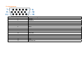
Pin Assignments
Pin Number
15-Pin Side of the Signal Cable
1
Video-Red
2
Video-Green
3
Video-Blue
4
N.C.
5
Ground
6
GND-R
7
GND-G
8
GND-B
9
+5V
10
Detect Cable
11
N.C.
12
DDC-Serial data
13
H-sync
14
V-sync
15
DDC-Serial clock
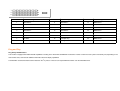
Pin No.
Signal Name
Pin No.
Signal Name
Pin No.
Signal Name
1
TMDS Data 2-
9
TMDS Data 1-
17
TMDS Data 0-
2
TMDS Data 2+
10
TMDS Data 1+
18
TMDS Data 0+
3
TMDS Data 2/4 Shield
11
TMDS Data 1/3 Shield
19
TMDS Data 0/5 Shield
4
TMDS Data 4-
12
TMDS Data 3-
20
TMDS Data 5-
5
TMDS Data 4+
13
TMDS Data 3+
21
TMDS Data 5+
6
DDC Clock
14
+5V Power
22
TMDS Clock Shield
7
DDC Data
15
Ground(for+5V)
23
TMDS Clock +
8
N.C.
16
Hot Plug Detect
24
TMDS Clock -
Plug and Play
Plug & Play DDC2B Feature
This monitor is equipped with VESA DDC2B capabilities according to the VESA DDC STANDARD. It allows the monitor to inform the host system of its identity and, depending on the
level of DDC used, communicate additional information about its display capabilities.
The DDC2B is a bi-directional data channel based on the I2C protocol. The host can request EDID information over the DDC2B channel.