1
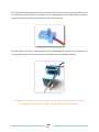
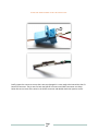
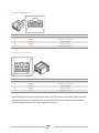
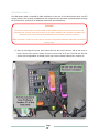
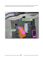
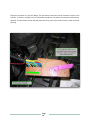
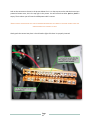
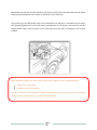
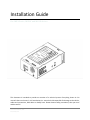
Installation Guide
For iMIV Classic, iMIV LE and MII LE devices
This document is intended to provide an overview of a technical process. Everything shown in this
manual is done at the user’s risk. Sensolutions Inc. cannot be held responsible for damage to the vehicle,
cables and connections, iMIV device or bodily harm. Please observe safety precautions, take your time
and be careful!
Version: 2.0
Version Date: March 3, 2010
Prepared By: MB
© Sensolutions Inc. 2010
Congratulations on your new iMIV or MII purchase! We hope the device will provide hours of
entertainment in an easy to use manner. Before beginning the installation please read the instructions
pertaining to your device in their entirety and ensure that all the ordered cables are in the box.
If anything remains unclear please do not hesitate to contact us, we are here to help!
Contents
Installation Options ....................................................................................................................................... 4
Front Mount .............................................................................................................................................. 4
DVD RTI ..................................................................................................................................................... 4
Melbus Prepped ........................................................................................................................................ 4
Installing the Device ...................................................................................................................................... 5
Front Mount Installation ........................................................................................................................... 5
DVD RTI Installation .................................................................................................................................. 6
Melbus Prepped Installation ..................................................................................................................... 7
Replacing Factory Peripherals ................................................................................................................... 8
Special Operations ........................................................................................................................................ 8
Reversing Camera Installation .................................................................................................................. 8
Reversing Camera Connector ................................................................................................................... 9
Universal Video Output Cable................................................................................................................... 9
Daisy Chain Melbus Cable ....................................................................................................................... 10
CD Based RTI Installation ........................................................................................................................ 10
REM Power Cable .................................................................................................................................... 14
Page 2
Intentionally Left Blank
Page 3
Installation Options
Front Mount
Front Mount installation kits are intended for vehicles that do not have an RTI system installed, are not
Melbus prepped, but may have an aftermarket LCD screen. The installation is completely plug and play
and allows the iMIV to be installed in the center drive tunnel, beside the glove box or under the front
seat.
Please ensure that your kit includes the following cables:
Power Harness Y-Adaptor PN: 24-CA-VOLVO-P00
Front Mount Power Cable PN: 24-CA-VOLVO-P04
80cm Long Melbus Cable PN: 24-CA-DIN01-DBUS08
If you have an iMIV Classic or iMIV LE it will also include an iPod cable - these vary by device.
DVD RTI
The DVD RTI kits are intended for vehicles that are equipped with a DVD based RTI system. The
installation is completely plug and play and allows the iMIV or MII to be installed in the rear of the
vehicle. It is recommended that the device be attached to the RTI mounting bracket. For CD RTI systems
please see the section titled ‘CD Based RTI Installation.’
Please ensure that your kit includes the following cables:
425cm Long iPod iVA Cable PN: 24-CA-IPOD-13DIN-43A
RTI Power and Video Cable PN: 24-CA-VOLVO-P08 or PN: 24-CA-VOLVO-P07
60cm Long Melbus Cable PM: 24-CA-DIN01-DBUS-06
If you have an iMIV Classic or iMIV LE it will also include an iPod cable - these vary by device.
Melbus Prepped
Melbus Prepped installation kits are intended for vehicles that are equipped with a factory installed
Melbus cable to the rear of the vehicle. Vehicles that were purchased with Sirius Satellite Radio or the
Sat-Prep option have this cable. It is important to check to ensure that the cable is installed in the
vehicle. There have been cases where it is regardless of the purchased options.
Please ensure you have the following cables:
Generic Power Cable PN: 24-CA-GEN-P02 or REM Power Cable PN: 24-CA-VOLVO-P03
If you have an iMIV Classic or iMIV LE it will also include an iPod cable - these vary by device.
Page 4
Installing the Device
Front Mount Installation
WARNING !
THE IGNITION SWITCH MUST BE IN POSITION 0 THE KEY REMOVED BEFORE THE NEGATIVE BATTERY LEAD IS
DISCONNECTED . FAILURE TO DO SO WILL RESULT IN AN AIRBAG WARNING LIGHT . ALWAYS DISCONNECT THE
NEGATIVE LEAD OF THE BATTERY WHEN WORKING ON THE ELECTRICAL SYSTEM OF A VEHICLE .
WHEN THE WORK IS COMPLETE THE KEY MUST BE TURNED TO POSITION II BEFORE RECONNECTING THE NEGATIVE
BATTERY LEAD .
1) Remove the radio from the dash. The procedure for doing this varies by model and year.
Connect one end of the Melbus cable to the back of the radio. Often there are two DIN style
connectors; however the Melbus cable will only connect to one. Route the cable to where the
iMIV/MII is being installed.
2) Remove the power harness from the back of the radio and connect the Y-Harness Power Cable
in between the radio and the stock power harness. Connect the Front Mount Power Cable to the
empty connector of the Y-Harness cable and route it to where the iMIV/MII is being installed.
3) Connect the Melbus cable to the port labeled ‘Melbus’ on the iMIV/MII. Connect the power
cable to the blue connector labeled ‘Power’ on the iMIV/MII.
4) If you have an iMIV device route the iPod cable to where you want to store the iPod. Commonly
this is the center console or glove box. Connect the 13 pin DIN connector the port labeled ‘iPod’
on the iMIV device.
5) It is recommended that the iMIV/MII be secured to the vehicle with 3M DualLock or a similar
product. Ensure everything functions as it should and reinstall the radio and any trim panels that
were removed.
Page 5
DVD RTI Installation
WARNING !
THE IGNITION SWITCH MUST BE IN POSITION 0 THE KEY REMOVED BEFORE THE NEGATIVE BATTERY LEAD IS
DISCONNECTED . FAILURE TO DO SO WILL RESULT IN AN AIRBAG WARNING LIGHT. ALWAYS DISCONNECT THE
NEGATIVE LEAD OF THE BATTERY WHEN WORKING ON THE ELECTRICAL SYSTEM OF A VEHICLE .
WHEN THE WORK IS COMPLETE THE KEY MUST BE TURNED TO POSITION II BEFORE RECONNECTING THE NEGATIVE
BATTERY LEAD .
1) Connect the ‘Melbus Second in Chain Cable’ to the DVD RTI using the 13 pin right angled
connector. This will mate to the leftmost DIN connector on the DVD RTI.
2) Connect the green connector of the power cable to the DVD RTI system. If you have an LE series
device there also is a round black connector that is plug and play for one of our reversing
cameras. This does not need to be connected for iMIV/MII operation.
3) Connect the Melbus cable to the port labeled ‘Melbus’ on the iMIV/MII. Connect the power
cable to the blue connector labeled ‘Power’ on the iMIV/MII.
4) If you have an iMIV device route the iPod cable to where you want to store the iPod. Commonly
this is the center console or glove box. Connect the 13 pin DIN connector the port labeled ‘iPod’
on the iMIV device.
5) It is recommended that the iMIV/MII be secured to the vehicle with 3M DualLock or a similar
product. Ensure everything functions as it should and reinstall the radio and any trim panels that
were removed.
Page 6
Melbus Prepped Installation
WARNING !
THE IGNITION SWITCH MUST BE IN POSITION 0 THE KEY REMOVED BEFORE THE NEGATIVE BATTERY LEAD IS
DISCONNECTED . FAILURE TO DO SO WILL RESULT IN AN AIRBAG WARNING LIGHT . ALWAYS DISCONNECT THE
NEGATIVE LEAD OF THE BATTERY WHEN WORKING ON THE ELECTRICAL SYSTEM OF A VEHICLE .
WHEN THE WORK IS COMPLETE THE KEY MUST BE TURNED TO POSITION II BEFORE RECONNECTING THE NEGATIVE
BATTERY LEAD .
1) Connect the factory installed Melbus cable to the iMIV/MII device. Ensure that the other end is
plugged into the radio at the front of the vehicle.
2) Connect the ground lug of the Generic power cable to either a screw on the chassis or the
negative terminal of the battery.
3) Using the included ScotchLock connector attach the red (positive) lead of the Generic Power
Cable to a constant +12v source. This means one that does not ‘turn off’ when the key is
removed from the vehicle. Failure to do this will result in improper operation of the iMIV/MII
device.
4) Connect the blue connector of the Generic Power Cable to the iMIV/MII device.
5) If you have an iMIV device route the iPod cable to where you want to store the iPod. Commonly
this is the center console or glove box. Connect the 13 pin DIN connector the port labeled ‘iPod’
on the iMIV device.
6) It is recommended that the iMIV/MII be secured to the vehicle with 3M DualLock or a similar
product. Ensure everything functions as it should and reinstall the radio and any trim panels that
were removed.
Page 7
Replacing Factory Peripherals
All iMIV devices were designed to utilize the same high quality connectors the Volvo uses for their
peripherals. If you are removing factory Satellite Radio, a factory iPod adaptor or a TV Tuner it is possible
to reuse the original power and Melbus cables.
It is not possible to reuse the original iPod cable from the factory adaptor however. Please note that the
TV Tuner must be removed for all iMIV/MII installations.
Special Operations
Reversing Camera Installation
The high quality ‘X1’ reversing camera available at our website is plug and play for all DVD RTI based
installations. If you purchased an iMIV Classic you will need the iMIV Classic Reversing Cable PN: 24-CABKC-06. LE series devices utilize the round black connector on the power cable that is included in all DVD
RTI installation packages.
1) Mount the reversing camera using either the included screws or double sided tape. Commonly
used is the ridge by the license plate.
2) Route the cable to the location of the iMIV/MII. If you are using an LE series device simply
connect the small round connector to the black connector of the Power and Camera harness.
This provides power and video to the camera.
3) For iMIV Classic devices connect the round camera connector to the round black connector of
the 24-CA-BKC-06 harness. Plug the green connector into the iMIV Classic port labeled ‘Camera.’
4) Apply the reversing camera firmware patch – available at www.imiv.ca – to the iMIV/MII. This
allows the iMIV/MII to override any video feed going into the RTI screen when reverse gear is
selected. This patch is applied like standard firmware; please see the operation manual for
details on how to do this.
5) Reinstall any removed trim panels.
Page 8
Reversing Camera Connector
If you do not wish to use our ‘X1’ reversing camera then you can purchase just the connector that goes
into the port labeled ‘Camera’ of the iMIV Classic. Utilization of a different style reversing camera with
LE series devices is not easily possible.
The Reversing Camera Connector is supplied with five crimp contacts, one as a spare. Looking at the
connector in the iMIV Classic and starting from left to right, the pin out is as follows:
Ground
Switched Power In
Video Ground
Video Signal
Switched power should only be enabled when the reverse lights are on, as this overrides any video feed
that the iMIV Classic might be displaying.
Please Note: The factory Volvo RTI screen uses a PAL signal only, NTSC cameras will not function
properly. Sensolutions Inc. cannot provide technical support for installing an unsupported camera or
offer warranty for iMIV Classic devices that are damaged due to incorrect wiring.
Universal Video Output Cable
If you purchased an iMIV Classic but have an aftermarket LCD screen it is possible to connect the video
feed from the iMIV Classic to it using the Universal Video Out Cable. The cable comes with pre-crimped
connecters that simply need to be inserted into the existing blue power connector of the iMIV Classic.
With the tab of the connector and the side where the wire exits facing toward you the pin out is as
follows, starting right to left.
1)
2)
3)
4)
5)
12v Positive In
12v Negative In
Switched Positive Out
Video Ground
Video Out
Bend up the safety latch of the blue connector and insert the black wire into location four and the white
wire into location five. Push the retaining latch back down and reinsert the connector back into the iMIV
Classic.
Please Note: Sensolutions Inc. cannot provide technical support for installing generic video screens or
this cable, or provide warranty for iMIV devices or wiring that is damaged due an incorrect installation.
Page 9
Daisy Chain Melbus Cable
Based on customer feedback Sensolutions now offers a daisy chain Melbus cable that allows several
Melbus devices to be connected at one time. It is intended for connecting several iMIV devices together,
or an iMIV device and factory peripheral such as a CD Changer or Satellite Radio.
Installation is as simple as connecting the female end of the cable to the existing Melbus cable and the
male ends to the Melbus devices. Please note that two devices cannot exist on the same radio channel.
Ie, you cannot have the CD Changer and an iMIV/MII device emulating a CD Changer connected at the
same time.
CD Based RTI Installation
For customers who have vehicles that are equipped with a CD based RTI system, we provide the CD RTI
connector. This connector is for customers who wish to install an iMIV Classic, iMIV LE or MII LE device
alongside an existing CD based RTI system. This will provide power for the iMIV device from the CD RTI
system. The main reason that we do not officially support CD based RTI devices is the inconsistent video
performance. Some customers will see black and white images, while others will see color. This can be
constant, or infrequent when switching channels. Audio is not affected, and all other features function
as designed.
This requires one of our cables with the large green DVD-RTI connectors. In order for the pins to be
inserted into the new connector they must be removed from the original connector unharmed. Note
that there are two black wires in the DVD RTI connector, do not get these reversed!
PLEASE NOTE THAT WHILE A BLUE POWER CONNECTOR IS SHOWN IN THIS DOCUMENT, THE PROCESS
IS THE SAME FOR ALL VOLVO STYLE CONNECTORS RELATED TO AN I MIV INSTALLATION .
To remove the pins you will need a small elongated object with an approximate diameter of 1.5mm.
Small hex tools, dentist’s picks, solid wire and jeweller’s screwdrivers can all be used.
Start by removing the cable from its packaging; if you are reconfiguring the pins to be used in a CD based
RTI system you will be removing the pins from the large green connector that is intended to plug into
the DVD based RTI system.
You will notice one side of the connector has a latch that clicks into place on the connector body, as
shown below.
Page
10
This clip needs to be pulled away from the connector body. There are latches that point towards the end
of the connector that the wires are coming out of. By pushing gently with a small blade screwdriver
away from the wires and up, the clip will release. It will look like below:
Next will need to insert your ~1.5mm rod into the hole directly above the wire you want to release. This
will compress the retaining clips on the contact and allow the wire to be gently pulled out.
THE WIRE AND CONNECTOR SHOULD SLIDE OUT RELATIVELY EASY. TUGGING ON THE CONNECTOR WILL ONLY
DEFORM IT AND POSSIBLY BREAK THE CRIMP . DO NOT USE PLIERS TO GRAB THE WIRES.
Page
11
IT MAY TAKE SOME PATIENCE TO GET THE CONTACT OUT.
Briefly inspect the contact to ensure that it was not damaged. It is now ready to be inserted into the CD
based RTI connector. The pin outs for both the DVD RTI connector and CD RTI connector are shown
below. Be sure to insert all the wires in the CD RTI connector and double check their position and fit.
Page
12
DVD RTI CONNECTOR PIN OUT
Pin #
1
2
3
4
10
Wire Colour
Green
Black
Black
White
Red
Wire Function
iMIV/MII Ground
RTI Screen Ground
Signal Ground
Signal Positive
iMIV/MII Positive
CD RTI CONNECTOR PIN OUT
Pin #
13
8
7
1
6
Wire Colour
Green
Black
Black
White
Red
Wire Function
iMIV/MII Ground
RTI Screen Ground
Signal Ground
Signal Positive
iMIV/MII Positive
After inserting the pins and ensuring they are secure, plug the connector into the RTI system and check
that everything functions as designed. If not, remove the connector from the RTI system and double
check the locations of the pins. It is easy to get them incorrect!
Page
13
REM Power Cable
The REM power cable is intended for iMIV installations in the rear of the vehicle when there is no RTI
system present. The contacts are added into the brown fuse box connector and draws power through
the fuse box itself. It allows for an OEM type install with minimal difficulty.
WARNING !
THE IGNITION SWITCH MUST BE IN POSITION 0 THE KEY REMOVED BEFORE THE NEGATIVE BATTERY LEAD IS
DISCONNECTED . FAILURE TO DO SO WILL RESULT IN AN AIRBAG WARNING LIGHT . ALWAYS DISCONNECT THE
NEGATIVE LEAD OF THE BATTERY WHEN WORKING ON THE ELECTRICAL SYSTEM OF A VEHICLE .
WHEN THE WORK IS COMPLETE THE KEY MUST BE TURNED TO POSITION II BEFORE RECONNECTING THE NEGATIVE
BATTERY LEAD .
1) Start by removing the interior panel above the fuse box on the driver’s side of the trunk or
hatch. Consult your owner’s manual if you are unsure how to do this. The fuse box will look
similar to the image below. As stated, ensure you put the included 3 Amp fuse in location 17.
Page
14
To remove the brown connector, push in the brown tab near the bottom and pull up the pink coloured
latch toward to the top of the vehicle. The connector can now be removed from the socket.
Page
15
The brown connector is a two part design. The side with the pink latch can be removed to access to the
contacts. To do this, carefully insert a small blade screwdriver into where the two parts meet and pry
upwards. This will release a small tab and allows the inner piece to be slid out from the main connector
housing.
Page
16
Look at the connector as shown in the picture below. Pin 1 is on the top row on the side that inserts into
protective brown cover; this is the top right in the picture. You will notice that either pin 8 or pin 27 is
empty. That is where you will insert the REM power cable’s contact.
DOUBLE COUNT TO MAKE SURE THAT THE PIN IS BEING INSERTED INTO THE CORRECT LOCATION . DOUBLE CHECK THE
ORIENTATION OF THE CONTACT AS WELL .
Gently push the contact into place. It should make a light click when it is properly inserted.
Page
17
Reassemble the two part fuse box connector and install it back into the fuse box. Push the pink plastic
clamp towards the bottom of the vehicle. It should not have to be forced.
The ground lug of the REM power cable can be attached to any bolt that is threaded into bare metal.
The intended ground point is near the battery compartment on the driver’s side trunk sill; see the
diagram below. Other common points are the mounting screws of the RIT, CD Changer or SAT receiver
brackets.
ONCE THE BROWN CONNECTOR IS SEATED , AND THE IMIV DEVICE CONNECTED , YOU CAN RESTORE POWER.
TURN THE KEY TO POSITION II
RECONNECT THE BATTERY GROUND .
FAILURE TO HAVE THE KEY IN POSITION II BEFORE RECONNECTING THE BATTERY WILL RESULT IN AN AIRBAG
WARNING LIGHT THAT WILL HAVE TO BE CLEARED BY THE DEALERSHIP .
Page
18
Have questions? Comments? Sensolutions Inc. can be reached:
By email:
[email protected] or
[email protected]
By phone:
+1.403.202.0275
By fax:
+1.403.202.2588
Or by mail:
Sensolutions Inc.
250031 Mountain View Trail
Calgary, AB T3K-3W5
Canada
This document and its contents are the property of Sensolutions Inc. It may not be modified without express written permission from
Sensolutions Inc. It may be distributed in its entirety to help with the installation and operation of iMIV and MII devices. This document and the
contents of this document may not be modified without express written permission from Sensolutions Inc.
Page
19