1
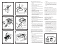
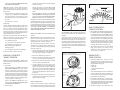
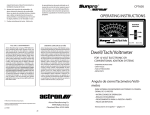
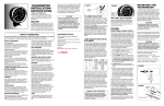
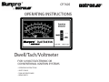
CP7605
OPERATING INSTRUCTIONS
Dwell/Tach/Voltmeter
FOR 12 VOLT ELECTRONIC OR
CONVENTIONAL IGNITION SYSTEMS
• OPERATING INSTRUCTIONS
• SAFETY RULES
• TUNE-UP PROCEDURES
• REPAIR PARTS
SAFETY GUIDELINES
TO PREVENT ACCIDENTS THAT COULD RESULT IN SERIOUS INJURY AND/OR DAMAGE TO YOUR VEHICLE OR TEST EQUIPMENT, CAREFULLY FOLLOW THESE SAFETY
RULES AND TEST PROCEDURES
SAFETY EQUIPMENT
Fire Extinguisher
Never work on your car without having a suitable
fire extinguisher handy. A 5-lb or larger CO2 or
dry chemical unit specified for gasoline/chemical/electrical fires is recommended.
Fireproof Container
Rags and flammable liquids should be stored only
in fireproof, closed metal containers. A gasolinesoaked rag should be allowed to dry thoroughly
outdoors before being discarded.
Safety Goggles
We recommend wearing safety goggles when
working on your car, to protect your eyes from
battery acid, gasoline, and dust and dirt flying off
moving engine parts.
NOTE: Never look directly into the carburetor throat
while the engine is cranking or running, as sudden
backfire can cause burns.
LOOSE CLOTHING AND LONG HAIR
(MOVING PARTS)
Be very careful not to get your hands, hair or clothes
near any moving parts such as fan blades, belts
and pulleys or throttle and transmission linkages.
Never wear neckties or loose clothing when working on your car.
JEWELRY
Never wear wrist watches, rings or other jewelry
when working on your car. You’ll avoid the possibility of catching on moving parts or causing
an electrical short circuit which could shock or
burn you.
VENTILATION
The carbon monoxide in exhaust gas is highly toxic.
To avoid asphyxiation, always operate vehicle in a
well-ventilated area. If vehicle is in an enclosed area,
exhaust should be routed directly to the outside
via leakproof exhaust hose.
SETTING THE BRAKE
Make sure that your car is in Park or Neutral, and
that the parking brake is firmly set.
NOTE: Some vehicles have an automatic release
on the parking brake when the gear shift lever
is removed from the PARK position. This feature
must be disabled when it is necessary (for testing)
to have the parking brake engaged when in the
DRIVE position. Refer to your vehicle service manual
for more information.
HOT SURFACES
Avoid contact with hot surfaces such as exhaust
manifolds and pipes, mufflers (catalytic converters),
radiator and hoses. Never remove the radiator cap
while the engine is hot, as escaping coolant under
pressure may seriously burn you.
SMOKING AND OPEN FLAMES
Never smoke while working on your car. Gasoline
vapor is highly flammable, and the gas formed in
a charging battery is explosive.
BATTERY
Do not lay tools or equipment on the battery. Accidentally grounding the“HOT”battery terminal can
shock or burn you and damage wiring, the battery
or your tools and testers. Be careful of contact with
battery acid. It can burn holes in your clothing and
burn your skin or eyes.
When operating any test instrument from an
auxiliary battery, connect a jumper wire between
the negative terminal of the auxiliary battery and
ground on the vehicle under test. When working
in a garage or other enclosed area, auxiliary battery should be located at least 18 inches above
the floor to minimize the possibility of igniting
gasoline vapors
HIGH VOLTAGE
High voltage — 30,000 to 50,000 volts — is present
in the ignition coil, distributor cap, ignition wires
and spark plugs. When handling ignition wires
while the engine is running, use insulated pliers to
avoid a shock. While not lethal, a shock may cause
you to jerk involuntarily and hurt yourself.
JACK
The jack supplied with the vehicle should be used
only for changing wheels. Never crawl under car
or run engine while vehicle is on a jack.
IMPORTANT
THIS MANUAL PRESENTS COMPLETE HOOKUP INSTRUCTIONS FOR THE
DWELL/TACH/VOLTMETER, IT ALSO DESCRIBES MANY OF THE TESTS THAT THIS
INSTRUMENT IS CAPABLE OF PERFORMING AS WELL AS WHEN THEY SHOULD
BE USED BASED ON VEHICLE PERFORMANCE, TUNE-UP OR TROUBLE ENCOUNTERED. CONSULT YOUR VEHICLE SERVICE MANUAL FOR SPECIFIC TUNE-UP INFORMATION AND TEST PROCEDURES. ALWAYS FOLLOW THE MANUFACTURER’S
SPECIFICATIONS AND TEST PROCEDURES FOR ADJUSTING DWELL ANGLE AND
IDLE SPEED, ESPECIALLY ON VEHICLES WITH MODERN ELECTRONIC IGNITION
AND EMISSION CONTROLS. DO NOT ATTEMPT TO SERVICE A VEHICLE WITHOUT
THE MANUFACTURER’S INSTRUCTIONS AND SPECIFICATIONS.
ACCESSORIES
FUNCTIONS, CONNECTIONS AND ACCESSORIES
Fig. 3
See Figure 2.
of the instrument.
DESCRIPTION
The Model CP7605 Dwell/Tach/Voltmeter has a
clearly labeled function switch and meter as shown
in the Master Hookup diagram, Figure 1 below.
1. METER
This meter displays the following scales:
• Volts
0-16
• RPM
0-2000 (8 cylinder)
0-4000(4cylinder
– multiply
3. TEST LEAD
Hook this lead to the proper test point in the
vehicle to perform tests as required and as
described below:
VOLTAGE MEASUREMENTS
GREEN CLIP – Connect to the Positive (+) voltage source to be measured. (+ Battery terminal,
alternator output terminal, lamp socket, etc.).
BLACK CLIP – Vehicle ground.
CAUTION!
8 cylinder scale
by 2)
• RPM
0-2500 (6 cylinder)
• Dwell
0-45 degrees (8 cylinder)
0-90 degrees (4
Avoid connecting the BLACK CLIP to the
negative(-) battery terminal or any fuel system components in the event that glasses are
present which could explode from sparking
connections.
cylinder–
multiply 8 cylinder by 2)
• Dwell
0-60 degrees (6 cylinder)
• Points
OK/Defective
DWELL/TACH/BREAKER POINT RESISTANCE
MEASUREMENT
GREEN CLIP – Connect to the Tach or negative
(-) ignition coil terminal. See Figures 3 through
10 for specific applications
2. FUNCTION SELECTOR
This selects the RPM, Dwell, or Volts functions
BLACK CLIP – Vehicle Ground. See CAUTION
under voltage measurements.
1. GM DIAGNOSTIC ADAPTOR
The GM Diagnostic Adaptor is used to make
connection to vehicle equipped with the GM Diagnostic Connector, (1976 –1982). It is also used
to make connection to Toyota vehicles which
use the IIA (Integrated Ignition Assembly). See
Figures 9 and 10 for adaptor application.
TO BALLAST
GREEN
CLIP
(BAT.)
CONTROL
UNIT
2. GM HEI ADAPTOR
The GM HEI Adaptor is used to provide connection to the “TACH” terminal on GM HEI systems.
See Figure 7 for typical installation.
3. FORD COIL CLIP
The Ford Coil Clip is used for ignition systems
which have booted ignition coil connections.
See Figure 4 for clip application.
TO CONTROL
UNIT
COIL
All Chrysler Corporation Electronic Ignitions, 6 & 8 cylinder shown
1972 - 1986
Fig. 4
ELECTRICAL SYSTEM TESTS –
"VOLTS" POSITION
Fig. 2
Primary Tach/Dwell Connection –
GREEN Clip
TO IGNITION
SWITCH
Accessories
3
TO DIST.
FORD
ADAPTER
GREEN
CLIP
1
Fig. 1
Master Hookup Diagram
Primary Tach Connection —
GREEN Clip
2
1974 Ford Electronic and All Breaker
Points Ignition Systems
Fig. 5
BLACK
ENGINE
GROUND
Primary Tach Connection —
GREEN Clip
GREEN
CLIP
DIST. OR
TACH
GREEN
BAT.
DISTRIBUTOR
COIL
Ford Solid State & Dura Spark systems
1975 - 1986
Fig. 6
Fig. 9
Primary Tach Connection —
GREEN Clip
Primary Tach Connection —
GREEN Clip
2. BLACK CLIP – Connect to Vehicle Ground.
SPADE
TERMINAL
ADAPTER
GREEN
CLIP
GREEN
CLIP
BASIC SYSTEM CHECK – Charging Voltage
1. GREEN CLIP – Connect to the Positive (+) Battery
terminal.
3. FUNCTION SELECTOR – Volts
4. Start engine and allow it to warm up completely.
Operate it at curb idle.
5. With all accessories off observe the 16 volt scale
on the analyzer.
6. Normal Result – 13.2 to 15.2 volts or as specified
in the vehicle service manual.
7. FUNCTION SELECTOR – RPM
GM Diagnostic Connector and
Delco HEI Systems 1976 - 1982
Ford TFI Systems 1981 - 1986
Fig. 7
Fig. 10
Primary Tach Connection —
GREEN Clip
Primary Tach Connection —
GREEN Clip
TO
IGNITION
SWITCH
INSERT
DIAGNOSTIC
ADAPTER
GREEN
CLIP
REMOVE CAP
FROM TACH
TEST CONNECTOR
GREEN
CLIP
ADAPTER
Toyota IIA (Integrated Ignition Assembly) 1983 - 1986
Delco HEI 1974 - 1986 Integral Coil
8. Select a step on the fast idle cam which will
maintain engine speed between l800 and 2000
RPM (or have an assistant hold engine speed
in this range) through Step 12.
Fig. 11
Primary Tach Connection —
GREEN Clip
Performance Check ONLY
Note: This is NOT a Tach Connection point.
DWELL CONNECTOR (GREEN)
NOTE: The voltmeter function of this instrument can
be used anywhere the vehicle service manual calls
for voltage measurement except in those applications which call for 10 Megohm input impedance
or a digital voltmeter.
10. Observe the 16 volt scale on the analyzer. The
voltage should not have changed from Step 6
more than about .5 volts.
IGNITION SYSTEM TEST –
"VOLTS" POSITION
11. Load the electrical system by turning on the
lights, Hi fan, and wipers.
BREAKER POINT RESISTANCE TEST (Breaker Point
Systems Only)
12. Observe the 16 volt scale on the analyzer. The
voltage should not drop below about 13.0
volts.
1. Visually check the breaker points and associated wiring and connections. Check to see that
the lead from the distributor to the Negative
(-) terminal of the ignition coil is not damaged
(nicked insulation, etc.)
13. Shut off all accessories, return the engine to
curb idle, and shut it off. If the results obtained
in Step 6, 10 or 12 are significantly different
from those shown or from the vehicle service
manual values, further diagnosis is required:
see your vehicle service manual.
If the engine cranks slowly or not at all, the battery,
cranking motor, and associated wiring may be
at fault. Check the cranking voltage as indicated
below.
1. Connect the analyzer to the vehicle battery as
shown in Figure 1.
2. Disable the engine from starting as shown in
Figure 12 or as explained in your vehicle service
manual
GREEN
CLIP
MISCELLANEOUS VOLTAGE TESTS
This instrument can perform many of the voltage
tests called out in the vehicle service manual, such
as voltages at lamp sockets, motors, solenoids
and relays.
9. FUNCTION SELECTOR – Volts
CRANKING VOLTAGE AND BATTERY CONDITION
Fig. 8
diagnosis.
7. If battery voltage remains abnormally high
(above approximately 10.5 volts) on a slow
or no cranking engine, the problem may be
loose or corroded connection(s) in the cranking
circuit.
2. Remove the distributor cap and inspect the
breaker points. Properly adjusted breaker
points become light gray in color in normal
use. If they are blued, blackened or pitted, they
have exceeded their normal life.
3. To prevent the engine from starting, disable
the ignition system by grounding the coil tower
wire as shown in Figure 12.
4. Connect the GREEN and BLACK clips as de-
Fig. 12
Disabling Procedure
Breaker Point Ignition System
3. FUNCTION SELECTOR – Volts
GREEN CLIP or
Ground Jumper
– See Vehicle
Service Manual
Delco HEI 1974 - 1986 External Coil
GM C3 (Computer Command Control)
4. Crank the engine while observing the 16 volt
scale on the analyzer.
5. Normal Result – 9.6 volts or more at 70°F. Voltage
will drop slightly as temperature decreases.
6. If the results are significantly out of specification
consult your vehicle service manual for further
ENGINE GROUND
scribed under DWELL/TACH/BREAKER POINT
RESISTANCE MEASUREMENTS
Start the engine and allow it to warm up (upper
radiator hose hot.)
NOTE: When testing a vehicle with dual points,
alternately block one set of points open with a
piece of insulating material while the other set is
being tested.
Operate the engine at curb idle OR the RPM
specified by the vehicle emission control label
or the vehicle service manual for measuring
dwell.
5. Turn the ignition key ON. If the meter reads
voltage, (12.5 - 13.0) the points are OPEN. Crank
the engine a fraction of a revolution at a time
until the meter reads in the left hand area of
the scale.
Check the RPM by switching the FUNCTION
SELECTOR TO RPM and reading the appropriate
meter scale. Return the FUNCTION SELECTOR to
DWELL and observe the correct dwell scale
The points are now closed.
Test Results:
Normal – Meter reads in the OK zone of the Points
scale. The Analyzer may indicate high point resistance on a new set of points until they have been
run in the vehicle for a few miles and have been
properly seated. This condition may be ignored as
long as any defects discovered during the previous
visual check have been corrected.
Abnormal – If the meter indicates in the Bad zone
when the points are closed, the points may be
defective or the following faults may exist:
Poor distributor ground
Poor connection on the primary lead from
the distributor to the ignition coil
Defective distributor pigtail lead
Misaligned points
Poor points/plate ground inside distributor
Fig. 13
Typical General Motors
Breaker Points Distributor
On GM distributors with a small metal slide cover,
lift the cover and insert a l/8" Allen wrench in the
adjusting screw socket and adjust the dwell by
turning the wrench, as shown in Figure 13.
On Ford, Chrysler, American Motors, and other
distributors not equipped with a small metal access slide cover, perform the following steps while
referring to Figure 14.
MORE THAN 3 DEGREES
1/8" ALLEN
WRENCH
ADJUSTMENT
SCREW
checking DWELL angle. Usually, the vacuum hose
must be disconnected from the distributor and
plugged
Increase the engine speed from idle to about
1500 RPM and note the dwell angle (Figure 15).
Return the engine speed to idle and again note
the dwell angle. If the difference between the two
dwell angle readings is more than 3 degrees, check
for excessive wear in the breaker point plate and
couplings or excessive wear in the distributor shaft
gear and bushings.
Fig. 14
IGNITION SYSTEM TEST –
"DWELL" POSITION
2. Remove the distributor cap and rotor.
(All, except Delco-Remy Sliding Window Distributors)
DWELL TEST AND ADJUSTMENT – Breaker Point
Systems Only or Transistorized Systems which Use
Breaker Points.
4. With ignition switch ON and engine cranking
observe reading on the Dwell scale.
1. Preparation:
Before performing the DWELL TEST AND
ADJUSTMENT PROCEDURE, read the vehicle
emission control label or the vehicle service
manual to determine what should be done with
the vacuum hoses connected to the distributor
and the various advance/retard solenoids. Most
often, the vacuum hose must be disconnected
from the distributor and the end plugged with
a plastic golf “tee” or other plug.
Connect the GREEN and BLACK clips as described under TACH/DWELL/BREAKER POINT
RESISTANCE MEASUREMENTS.
2. Test Procedure:
6. Reassemble distributor and recheck dwell reading with engine operating at idle speed. Repeat
steps 5 and 6 if necessary.
DWELL VARIATION TEST
Read the owner’s manual or engine compartment
decal and follow the instructions regarding vacuum
line or advance-retard solenoid connections when
ADJUSTMENT
SLOTTED HOLE
LOCKING SCREW
BREAKER
POINTS
FUEL SYSTEM TESTS –
"DWELL" POSITION
1. General Motors C-3 (Computer Command Control) Mixture Control Solenoid Dwell (Carburetor equipped vehicles only). The GMC-3 system
controls Air/Fuel ratio with a mixture control
solenoid mounted in the carburetor. The basic
system performance check of this system calls
for the checking of the duty cycle or dwell of
the M/C solenoid. Note that regardless of the
number of cylinders in the vehicle, the reading
is always taken from the 6 cylinder scale.
2. This analyzer may be used to check C-3 Dwell
(duty cycle). Refer to your vehicle service
manual for hookup instructions and performance results. See Figure 11.
Dwell Adjustment
3. Connect a remote starter switch to the vehicle
or have an assistant crank the engine for you.
5. To adjust Dwell, loosen the locking screw
slightly and adjust the point gap with a feeler
gauge according to the procedure outlined in
the vehicle service manual. After adjustment,
tighten locking screw, and recheck dwell while
cranking engine. Repeat procedure if necessary.
(Figure 14.)
SECOND
READING
WINDOW
1. Remove coil wire from center tower of distributor
cap and ground the wire by connecting the loose
end to the engine or frame, See Figure 12.
Correct the defect and repeat the test.
Dwell Variation
FIRST
READING
NOTE: There is a direct relationship between dwell
and timing. However, it is only a one way relationship.
If you change the dwell angle of the breaker points,
you will automatically change the ignition timing.
Changing the timing, though, has no effect on the
dwell angle. FOR THIS REASON, IT IS IMPORTANT
TO RE-CHECK THE TIMING WHEN EVER THE DWELL
ANGLE HAS BEEN ADJUSTED.
DWELL ADJUSTMENT – Conventional Breaker Point
Systems
Fig. 15
BREAKER
POINTS
ADJUSTMENT
SCREW
ENGINE TESTS –
"RPM" POSITION
1. Carburetor Adjustments – There are several
adjustments which should be checked as part
of a performance tune-up. Those which require
engine RPM monitoring are:
a. Curb idle
b. Base idle
c. Solenoid Controlled idle
d. Fast idle
Your vehicle will likely have some combination
of these adjustments. Proper adjustment of
these settings is a requirement for good engine
performance and driveability.
2. Fuel Injection Adjustments – Some fuel injection systems have a minimum and maximum
authority adjustment which should be checked
during routine performance tune-up or whenever idle problems are encountered.
3. Miscellaneous Engine Test – Many of the test
procedures in your vehicle service manual
require the engine to run at a specific RPM during the test. Your instrument provides excellent
monitoring capabilities for this purpose.
Model CP7605
Replacement Parts
Key
No.
Part
No.
1
2
3
4
5
6
7
8
9
—
400-857
270-117
38-726
450-133
180-300
38-1342
1-1086
1-1085
400-855
2-219301
Description
Case, bottom
Screw, Case self-tap. #6-20 x 1"
Cable Assembly, Green and Black Clip
Cap, Glamour
Ford Adapter
GM Adapter
Switch Decal
Meter Decal
Window
Instruction Manual (Not shown)
NOTE: The circuit board and meter are not replacement parts
since the replacement of either requires recalibration of the instrument.
ACTRON
HAND TOOLS