1
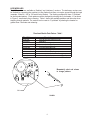
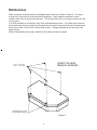
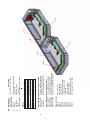
INSTALLATION
& OPERATION
MANUAL
XP 9500 FLUSH-MOUNT LIGHTBAR
XP 9500
FLUSH-MOUNT LIGHTBAR
Contents:
Introduction ............................................................. 2
Unpacking & Pre-Installation ................................... 2
Installation & Mounting ............................................ 3
Wiring Instructions ................................................... 4
LED Warning Devices ............................................. 4
Maintenance ............................................................ 6
Troubleshooting ....................................................... 7
Parts List ................................................................. 8
Dimensions ............................................................. 9
Notes ..................................................................... 10
Warranty ................................................................ 12
IMPORTANT:
Read all instructions and warnings before installing and using.
INSTALLER: This manual must be delivered to the end user of this equipment.
1
Introduction
The XP9500 is an LED lightbar that contains a series of polycarbonate “pods” mounted to a strong
aluminum extrusion. Angled lights in each pod project light to the intersections while forward facing
lights provide a strong signal straight ahead. The PriZmTM LED lightheads provide a high intensity
warning signal while drawing very little current. It is only 3" high and 7 ½” deep. Alley lights and
forward clear lights round out the options for the XP 9500. Properly configured, the XP 9500
meets all SAE, California Title 13, KKK and NFPA specifications.
!
WARNING!
The use of this or any warning device does not insure that all drivers can or will observe or react to an
emergency warning signal. Never take the right-of-way for granted. It is your responsibility to be sure you can
proceed safely before entering an intersection, driving against traffic, responding at a high rate of speed, or
walking on or around traffic lanes.
The effectiveness of this warning device is highly dependent upon correct mounting and wiring. Read and
follow the manufacturer’s instructions before installing or using this device. The vehicle operator should insure
daily that all features of the device operate correctly. In use, the vehicle operator should insure the projection
of the warning signal is not blocked by vehicle components (i.e.: open trunks or compartment doors), people,
vehicles, or other obstructions.
This equipment is intended for use by authorized personnel only. It is the user’s responsibility to understand
and obey all laws regarding emergency warning devices. The user should check all applicable city, state and
federal laws and regulations.
Public Safety Equipment, Inc., assumes no liability for any loss resulting from the use of this warning device.
Proper installation is vital to the performance of this warning device and the safe operation of the emergency
vehicle. It is important to recognize that the operator of the emergency vehicle is under psychological and
physiological stress caused by the emergency situation. The warning device should be installed in such a
manner as to: A) Not reduce the output performance of the system, B) Place the controls within convenient
reach of the operator so that he can operate the system without losing eye contact with the roadway.
Emergency warning devices often require high electrical voltages and/or currents. Properly protect and use
caution around live electrical connections. Grounding or shorting of electrical connections can cause high
current arcing, which can cause personal injury and/or severe vehicle damage, including fire.
PROPER INSTALLATION COMBINED WITH OPERATOR TRAINING IN THE PROPER USE OF EMERGENCY WARNING DEVICES IS ESSENTIAL TO INSURE THE SAFETY OF EMERGENCY PERSONNEL
AND THE PUBLIC.
Unpacking & Pre-Installation
Carefully remove the lightbar and place it on a flat surface, taking care not to scratch the lenses.
Examine the unit for transit damage. Report any damage to the carrier and keep the shipping box.
Standard lightbars are built to operate on 12 volt D.C. negative ground vehicles. If you have an
electrical system other than this and have not ordered a specially wired lightbar, contact the factory
for instructions.
Test the unit before installation. To test, touch the black wire to ground and the other wires to
+12VDC (an automotive battery is preferable for this test). A battery charger may be used, but
please note that some electronic options may not operate normally when powered by a battery
charger. If problems occur, at this point, contact the factory.
2
Installation & Mounting
Select the desired mounting location for the lightbar. This product is attached with 3/8" carriage
bolts whose centerlines are 2" below the top of the lightbar (Figure 1).
Locate the bolts along the back of the lightbar. The number of mounting bolts varies with the
length of the lightbar. Place a mounting bolt near each end of the frame. Space additional bolts
evenly across the remaining length. Locate 7/16" diameter clearance holes on the vehicle to work
with the bolt locations. Locate for easy access from the inside of the vehicle. Locate and drill a
minimum 3/4” diameter hole for the control cable exiting as shown in Figure 2 below. Insure the
cable jacket cannot be cut by sharp edges.
Route the cable and the bolts into their respective holes. Attach the washers and nuts to the bolts
from the inside of the vehicle. Apply caulk to all bolts and wires at the point of entry.
M O U N T IN G A S S E M B L Y /H A R D W A R E F O R X P 9 5 0 0
UPPER LENS
T 0 6 7 3 2 - S T E P B O L T 3 /8 -1 6 X 1 .5 "
T 0 6 5 3 3 - 3 /8 L O C K W A S H E R
2 .0
1 .2
FIGURE 1
T 0 6 5 5 1 - 3 /8 H E X N U T
T 0 1 5 7 8 - 3 /8 F L A T W A S H E R
LO W ER LEN S
AM BU LANCE
SHEET M ETAL
FRAME
STANDARD CABLE HOLE LOCATIONS FOR XP9500 FROM CENTERLINE OF BAR
CL
CL
CL
6 9/32"
1 POD
2 POD
3 POD
CL
6 9/32"
4 POD
CL
5 POD
FIGURE 2
CL
6 9/32"
6 POD
CL
7 POD
3
Wiring Instructions
!
WARNING!
Larger wires and tight connections will provide longer service life for components. For high current wires it
is highly recommended that terminal blocks or soldered connections be used with shrink tubing to protect
the connections. Do not use insulation displacement connectors (e.g. 3M® Scotchlock type connectors).
Route wiring using grommets and sealant when passing through compartment walls. Minimize the number
of splices to reduce voltage drop. High ambient temperatures (e.g. underhood) will significantly reduce the
current carrying capacity of wires, fuses, and circuit breakers. Use "SXL" type wire in engine compartment.
All wiring should conform to the minimum wire size and other recommendations of the manufacturer and be
protected from moving parts and hot surfaces. Looms, grommets, cable ties, and similar installation
hardware should be used to anchor and protect all wiring. Fuses or circuit breakers should be located as
close to the power takeoff points as possible and properly sized to protect the wiring and devices. Particular
attention should be paid to the location and method of making electrical connections and splices to protect
these points from corrosion and loss of conductivity. Ground terminations should only be made to
substantial chassis components, preferably directly to the vehicle battery. The user should install a fuse
sized to approximately 125% of the maximum Amp capacity in the supply line to protect against short
circuits. For example, a 30 Amp fuse should carry a maximum of 24 Amps. DO NOT USE 1/4" DIAMETER
GLASS FUSES AS THEY ARE NOT SUITABLE FOR CONTINUOUS DUTY IN SIZES ABOVE 15 AMPS.
Circuit breakers are very sensitive to high temperatures and will "false trip" when mounted in hot environments or operated close to their capacity.
Always refer to the wire tag attached to the lightbar cable to match lightbar functions with colored
wire. Several items may be controlled by the same wire. Extend all control wires to switching
device and make appropriate connections. The black ground wire must be securely attached to the
vehicle chassis to provide reliable grounding.
LED Warning Devices
WARNING!
!
This Product contains high intensity LED devices. To prevent eye damage, DO NOT stare
into light beam at close range.
LED Fusing Considerations
Although the average current draw per module is very low, due to the type of circuit used to power
each module, the instantaneous peak current to a module can be significantly higher during low
voltage conditions. To avoid prematurely blowing ATO style fuses or tripping breakers, it is
recommended the following rule-of-thumb be used to size fuses or breakers. This is especially
important in lightbars with many LED modules running off a single fused source.
Minimum fuse size calculation:
1.5 x (number of 6/8/12-up modules being fused) + .5 x (number of 3-up modules being fused)
Example:
XP9500 lightbar with 7 forward facing 6-up modules and 16 angled and end facing 3-up modules
Minimum fuse requirement for single fuse: (1.5 x 7) + (.5 x 16) = 18.5A minimum
Note:
Each 35 Watt halogen lamp requires 3A fusing. Each 55 Watt halogen lamp requires 5A fusing.
4
LED MODULES
The LED modules are available as “flashing” and “stationary” versions. The stationary versions can
be flashed by connecting the module(s) to any flasher that does not require ground through the load
(example: Code 3® 925 or 700 series relay flasher). The flashing modules will have "Cycleflash"
as the standard pattern. Flash patterns can be changed by shorting the 2-pin header, J1 as shown
in Figure 3, momentarily then releasing. Table 1 shows the available patterns and the order when
stepping through patterns. The module can be reset to "Cycleflash" by shorting the header for
greater than 5 seconds and releasing.
Directional Module Flash Pattern - Table 1
Flash Pattern
Cycle Flash
Steady-Burn
Five Flash
Quad Flash
Triple Flash
Double Flash
Fast Double Flash
NFPA
Quad Pop Flash
Triple Pop Flash
Description
Cycles through various patterns @ 70 fpm
Steady-Burn
Five Pulses per flash @ 70 fpm
Four Pulses per flash @ 70 fpm
Three Pulses per flash @ 70 fpm
Two Pulses per flash @ 70 fpm
Two Pulses per flash @ 85 fpm
Four Pulses, 70% Duty Cycle @ 75 fpm
Four Pulses per flash ( 3 equal, 1 extended) @ 70 fpm
Three Pulses per flash ( 2 equal, 1 extended) @ 70 fpm
Momentarily short and release
to change patterns
J1
PCB
FIGURE 3
5
Maintenance
Make sure power is disconnected to the lightbar before servicing. Refer to Figure 4. To remove
the top lens, remove the 4 screws around the perimeter. Place a blade screwdriver into the
notches at the front of the top lens and twist. This should lift the lens up enough to remove the top
lens by hand.
If an LED assembly is not working, refer to the troubleshooting section. If it needs to be removed,
disconnect power to the module by pulling apart the red quick connect terminal and unscrewing the
black ground lead. Remove the 2 sheet metal screws. Halogen assemblies are removed in the
same manner.
Before reassembling the top lens, make sure the gasket is properly seated.
XP9500 TOP LENS
REMOVAL PROCESS
T16320 - #8 SCREW
T16321 - #8 WASHER
SCREWDRIVER NOTCH
FOR OPENING LENSES
Figure 4
6
Troubleshooting
All XP9500 lightbars are thoroughly tested prior to shipment. However, should you encounter a
problem during installation or during the life of the product, follow the guide below for information
on repair and troubleshooting. Additional information may be obtained from the factory technical
help line at 314-996-2800.
LED MODULE
TROUBLESHOOTING GUIDE
Note: LED modules must be replaced as a module. There are no user serviceable parts.
PROBLEM
LED directional
module not
operating when
powered.
Lamp or LED
module does not
come on when it
should (based on
controller function)
QUESTIONS
N/A
POSSIBLE CAUSE
SOLUTION
a. Bad power/ground
connection.
a. Fix connection.
b. Defective module.
b. Replace module.
a. Bad lamp or defective
LED module
a. Replace lamp or LED module
b. Defective wiring
connection
b. Repair connection
a. Control box is damaged
a. Return to Code 3
Are the
controller
panel LED
indicators
functioning
properly?
Yes
No
7
8
2
3
4
5
6
Ref.
1
Pod)
Pod)
Pod)
Pod)
Pod)
Pod)
Pod)
Parts not shown
T51011
T08874
T08875
S27180
S24186
T16320
T16321
T16323
T01215
T02946
Clear upper lens
Right side endcap
Left side endcap
35 Watt Alley/Front light
55 Watt Alley/Front light
Lens Screw
Lens Screw washer
Frame/Lens gasket
#8 Screw-module mounting
#8 Screw-lower lens to frame
Other LED lighthead assemblies available
S27012-S27019
12-up LED/Reflector assembly
S27004-S27011
8u-p LED/Reflector assembly
S23963-S23986
6u-p Optix LED lighthead assembly
S23939-S23946
6-up OLP dual lighthead assembly
Other 3up LED lighthead assemblies available
S23957-S23962
Optix LED lighthead assembly
Call factory
OLP Single lighthead assembly
Call factory
OLP Dual lighthead assembly
(1
(2
(3
(4
(5
(6
(7
Mounting
Mounting
Mounting
Mounting
Mounting
Mounting
Mounting
Table 2
T16301
T16302
T16303
T16304
T16305
T16306
T16307
Frame
Frame
Frame
Frame
Frame
Frame
Frame
LED Lighthead Mounting Plate
Lens Spacer
Aluminum Frame
Lower Lens
6-up LED/Reflector Assembly
Description
3-up LED/Reflector Assembly
Part Number
S23995-S23998
S27000-S27003
S24148
T08873
See Table 2
T51001
S23987-S23994
1
2
6
3
4
5
XP 9500 OVERALL DIMENSIONS
DESCRIPTION
XP9512
XP9525
XP9538
XP9550
XP9563
XP9575
XP9588
PODS
LENGTH
1
2
3
4
5
6
7
12.500
25.062
37.625
50.188
62.750
75.313
87.875
9
DEPTH
7.375
7.375
7.375
7.375
7.375
7.375
7.375
HEIGHT
3.000
3.000
3.000
3.000
3.000
3.000
3.000
NOTES:
10
NOTES:
11
WARRANTY
This product was tested and found to be operational at the time of manufacture.
Provided this product is installed and operated in accordance with the manufacturer's
recommendations, Code 3®, Inc. guarantees all parts and components, except the halogen
lamps, for a period of 1 year, LED lighthead modules to a period of 5 years (unless otherwise expressed) from the date of purchase or delivery, whichever is later. Units demonstrated to be defective within the warranty period will be repaired or replaced at the factory
service center at no cost.
Use of a lamp or other electrical load of a wattage higher than installed or recommended by the factory, or use of inappropriate or inadequate wiring or circuit protection
causes this warranty to become void. Failure or destruction of the product resulting from
abuse or unusual use and/or accidents is not covered by this warranty. Use of non-Code 3
components and assemblies may cause damage to the system and/or personal injury, and
voids all warranties on Code 3 systems and components.
Code 3 shall in no way be liable for other damages including consequential, indirect or
special damages whether loss is due to negligence or breach of warranty.
CODE 3 MAKES NO OTHER EXPRESS OR IMPLIED WARRANTY INCLUDING,
WITHOUT LIMITATION, WARRANTIES OF FITNESS OR MERCHANTABILITY, WITH
RESPECT TO THIS PRODUCT.
PRODUCT RETURNS
In order to provide you with faster service, if you are going to return a product for repair
or replacement*, please contact our factory to obtain a Return Goods Authorization Number
(RGA number) before you ship the product to Code 3. Write the RGA number clearly on the
package near the mailing label. Be sure you use sufficient packing materials to avoid
damage to the product being returned while in transit.
*Code 3 reserves the right to repair or replace product at its discretion. Code 3 assumes no responsibility
or liability for expenses incurred for the removal and/or reinstallation of products requiring service and/or repair.
Code 3®, Inc.
10986 N. Warson Road
St. Louis, Missouri 63114-2029—USA
Ph. (314) 426-2700 Fax (314) 426-1337
www.code3pse.com
Code 3® is a registered trademark of Code 3, Inc.
Revision 0, 8/2007 - Instruction Book Part No. T16326
©2004 Code 3, Inc. Printed in USA
12