1
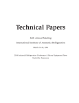
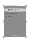
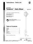
McDonnell & Miller
Series 101-A
Electric Water Feeder
Installation & Maintenance
Instructions
MM-307(F)
®
Applications:
with
For use on low pressure boilers with cold water feed.
The Series 101-A can be used with mechanical or
electronic low water cut-off controls.
QUICK
CHANGE
Cartridge
WARNING
Do not use automatic water feeders with manual reset LWCO’s.
Failure to follow this warning could cause flooding, property damage,
personal injury or death.
SPECIFICATIONS
150 psi (10.5 kg/cm2)
25 psi (1.76 kg/cm2)
5000 sq. ft. EDR
2,350,000 BTU/HR
Output Capacity
Maximum Water Temperature: 120˚F (49˚C)
Maximum Water Pressure:
Maximum Boiler Pressure:
Maximum Boiler Size:
Flow Data
Electrical Ratings
Model
101A-120
101A-24
Voltage
120V
24V
Full Load
40 VA
40 VA
Pressure Differential
psi (kg/cm2)
5
(.4)
10
(.7)
20
(1.4)
40
(2.8)
60
(4.2)
80
(5.6)
Flow Rate
gpm (lpm)
1.4
(5.3)
1.7
(6.4)
2.1
(7.9)
2.9
(11.0)
3.4
(12.9)
4.0
(15.1)
NOTE: 101A-24 includes a transformer with
120 volt primary and 24 volt/50VA secondary.
WARNING
ION
CAUT
WARN
ING
• Before using this product read and understand instructions.
• Save these instructions for future reference.
• All work must be performed by qualified personnel trained in the proper application, installation, and maintenance of plumbing, steam, and electrical equipment and/or systems in
accordance with all applicable codes and ordinances.
• Boiler manufacturer schematics should always be followed. In the event that the boiler
manufacturer’s schematic does not exist, or is not available from the boiler manufacturer,
refer to the schematics provided in this document.
• To prevent water damage check to make sure there is adequate floor drainage capacity.
Check all components in the system to insure that they will not leak in the event of an
overfeed condition.
• To prevent electrical shock, turn off the electrical power before making electrical connections.
Failure to follow this warning could cause property damage, personal injury or death.
INSTALLATION
STEP 1 - Determine Where to Install the Water Feeder
IMPORTANT
Boiler manufacturer schematics should always be followed. In the
event that the boiler manufacturer’s schematic does not exist, or is
not available from the boiler manufacturer, refer to the schematics
provided in this document.
Determine where to install the water feeder
based on the following requirements:
a. It must be installed within eyesight of the boiler.
b. A minimum 6” (152mm) clearance should be
allowed on all sides for servicing.
c. It must be installed in a horizontal pipe in the
upright position.
d. It should be installed on the cold water line.
6" (152mm)
6"
(152mm)
6"
(152mm)
FLOW
ARROW
6" (152mm)
Installation Diagram and Requirements
CITY WATER SUPPLY
a. Piping must be 1/2” (15mm) NPT
minimum.
UNION
WATER FEEDER
c. Arrow on feeder casting must point in
direction of flow into the boiler.
d. Install isolation valves and unions on
the inlet and outlet piping of the feeder
for easier trouble-shooting and repair/
replacement.
CHECK VALVE OR BACK
FLOW PREVENTER
(MAY BE REQUIRED BY
LOCAL CODE OR
ORDINANCES)
INLET VALVE
b. Full port/full flow valves rated for the
pressure/temperature of the system
and piping they are to be installed on.
BYPASS VALVE
OUTLET VALVE
UNION
FLOW ARROW
UNION
CONNECT TO
RETURN HEADER
ON BOILER
NOTE: DO NOT CONNECT
DIRECTLY TO BOILER SHELL
e. Install manual fill valve and bypass line
to allow for removal of the valve while
the boiler is in service.
STEP 2 - Electrical Installation
IMPORTANT
Boiler manufacturer schematics should always be followed. In the
event that the boiler manufacturer’s schematic does not exist, or is
not available from the boiler manufacturer, refer to the schematics
provided in this document.
NOTE
Before connecting water feeder, operate boiler and
check all safety devices.
2
NOTE
Unless otherwise noted, water feeder voltage
should be the same as the LWCO and burner
circuit voltage.
WARNING
• All work must be performed by qualified personnel trained in the proper application, installation, and
maintenace of plumbing, steam, and electrical equipment and/or systems in accordance with all applicable
codes and ordinances.
• To prevent electrical shock, turn off the electrical power before making electrical connections.
• To prevent an electrical fire or equipment damage, electrical wiring insulation must have a rating of
167˚F (75˚C) if the liquid’s temperature exceeds 180˚F (82˚C).
• To prevent an electrical fire or equipment damage, water feeder wiring must be on same circuit as all other
boiler controls.
Failure to follow this warning could cause property damage, personal injury or death.
a. Test the Low Water Cut-Off on the boiler.
b. Mark location of water level on sight glass where
Low Water Cut-Off turns off burner. This will be
used as reference to test the water feeder’s
operation.
LWCO
Level
c. Turn off all power to boiler and boiler controls.
ON
OF F
d. Using a flathead screwdriver, remove electrical
cover plate.
f. Connect electric conduit to the water feeder’s electrical
enclosure.
g. Based on the water feeder and low water cut-off combination you are installing, select proper
wiring diagram and proceed to that page.
Water Feeder
Model
101A-120
101A-24
101A-120
101A-24
101A-24
101A-120
&
&
&
&
&
&
Low Water Cut-Off
Page
Model
67 with 24V or 120V burner circuit ..........................................................................4
67 with 24V or 120V burner circuit .......................................................................4-5
67G with millivolt burner circuit ................................................................................5
67G with millivolt burner circuit ................................................................................5
PS-802-24................................................................................................................6
PS-801-120..............................................................................................................6
3
Wiring Diagram Legends
1. Bold lines indicate action to be taken in Step shown.
2. Regular black lines indicate existing wiring.
For McDonnell & Miller Model 101A-120 Water Feeder and Series 67 Low Water Cut-Off
with 120 volt burner circuit
h. Connect wire (A) from water feeder to burner circuit
Neutral wire.
BURNER
CIRCUIT
i. Install jumper between terminals 2 and 3 of the low
water cut-off.
JUMPER
j. Install wire (B) from water feeder to terminal 4 of the
low water cut-off.
1
2
3
4
NEUTRAL
HOT
120 VAC
SUPPLY
A
B
67 LOW WATER
CUT-OFF
101A
WATER FEEDER
For McDonnell & Miller Model 101A-120 Feeder and Series 67 Low Water Cut-Off
with 24 volt burner circuit
h. Install wire (A) from water feeder to 120 volt Neutral wire.
i. Install wire (B) from water feeder to terminal 4 of the low
water cut-off.
j. Install wire (C) from terminal 3 of the low water cut-off
to 120 volt Hot wire.
BURNER
CIRCUIT
1
2
3
4
NEUTRAL
120 VAC
HOT SUPPLY
24V
C
A
B
67 LOW WATER
CUT-OFF
101A
WATER FEEDER
For Model 101A-24 Water Feeder and Series 67 Low Water Cut-Off
with 24 volt burner circuit
h. Install wire (A) from burner circuit Neutral wire
to the transformer input Neutral terminal.
BURNER
CIRCUIT
i. Install wire (B) from burner circuit Hot wire to the
transformer input Hot terminal.
j. Install wire (C) from transformer output Neutral
terminal to the water feeder.
k. Install wire (D) from the water feeder to terminal 4
on the low water cut-off.
l. Install wire (E) from terminal 3 on the low water
cut-off to the transformer output Hot terminal.
1
2
3
4
D
67 LOW WATER
CUT-OFF
NEUTRAL
120 VAC
HOT SUPPLY
24V
E
B
C
101A
WATER FEEDER
A
24V TRANSFORMER
(101-24 V-48)
IMPORTANT
To prevent damage to the water feeder, a McDonnell
& Miller transformer Model 101-24V-48 must be used.
4
For Model 101A-24 Water Feeder and Series 67 Low Water Cut-Off
with 120 volt burner circuit
h. Install wire (A) from burner circuit Neutral wire to the
transformer input Neutral terminal.
BURNER
CIRCUIT
i. Install wire (B) from burner circuit Hot wire to the
transformer input Hot terminal.
j. Install wire (C) from transformer output Neutral
terminal to the water feeder.
k. Install wire (D) from the water feeder to terminal 4
on the low water cut-off.
1
2
3
4
NEUTRAL
120 VAC
HOT SUPPLY
B
E
A
C
D
24V TRANSFORMER
(101-24 V-48)
101A-24
WATER FEEDER
67 LOW WATER
CUT-OFF
l. Install wire (E) from terminal 3 on the low water
cut-off to the transformer output Hot terminal.
IMPORTANT
To prevent damage to the water feeder, a McDonnell
& Miller transformer Model 101-24V-48 must be used.
For Model 101A-120 Feeder and Model 67G with millivolt burner circuit
h. Install wire (A) from water feeder to 120 volt
Neutral wire.
MILLIVOLT
BURNER
CIRCUIT
i. Install wire (B) from water feeder to terminal 4
of the low water cut-off.
j. Install wire (C) from terminal 3 of the low water
cut-off to 120 volt Hot wire.
1
2
3
4
C
B
HOT
120 VAC
SUPPLY
NEUTRAL
101A
FEEDER
A
For Model 101A-24 Feeder and Model 67G with millivolt burner circuit
h. Install wire (A) from 120 volt circuit Neutral wire
to the transformer input Neutral terminal.
MILLIVOLT
BURNER
CIRCUIT
i. Install wire (B) from 120 volt circuit Hot wire to the
transformer input Hot terminal.
j. Install wire (C) from transformer output Neutral
terminal to the water feeder.
k. Install wire (D) from the water feeder to terminal 4
on the low water cut-off.
l. Install wire (E) from terminal 3 on the low water
cut-off to the transformer output Hot terminal.
B
E
1
2
3
4
D
120 VAC
SUPPLY
A
101A-24
24V TRANSFORMER
(101-24V-48)
C
IMPORTANT
To prevent damage to the water feeder, a McDonnell
& Miller transformer Model 101-24V-48 must be used.
5
For Model 101A-24 Water Feeder and Model PS-802-24 Low Water Cut-Off
Replace existing 24 volt transformer on boiler with the
McDonnell and Miller transformer Model 101-24 V-48
included with the Model 101A-24 water feeder.
PS-802-24 LOW WATER CUT-OFF
JUMPER BAR
N
H
C
W
B
BURNER
h. Install wire (A) from the water feeder to terminal N
on the low water cut-off.
B
i. Install wire (B) from the water feeder to terminal W
on the low water cut-off.
A
j. Install jumper bar or wire from terminal H to terminal
C on the low water cut-off.
24V TRANSFORMER
(101-24 V-48)
101A-24
WATER FEEDER
HOT NEUTRAL
120 VAC SUPPLY
IMPORTANT
To prevent damage to the water feeder, a McDonnell
& Miller transformer Model 101-24V-48 must be used.
For Model 101A-120 Water Feeder and Model PS-801-120 Low Water Cut-Off
h. Install wire (A) from the water feeder to terminal 2
on the low water cut-off.
i. Install wire (B) from the water feeder to terminal 4
on the low water cut-off.
PS-801-120
LOW WATER CUT-OFF
JUMPER
1
2
3
4
5
B
BURNER
CIRCUIT
101A
WATER
A FEEDER
HOT NEUTRAL
120 VAC SUPPLY
Reinstall electrical cover plate.
6
TESTING
NOTE: The water feeder will only restore the boiler
water level to approximately 1/2” to 1” (13-25mm)
above the burner cut-off level of the low water cut-off.
Burner Off (Cold) Test
Burner On (Hot) Test
1. Manually fill boiler until water level in the sight glass
is more than half filled.
1. Manually fill the boiler to the boiler manufacturer’s
recommended operating level.
2. With the room thermostat set at the lowest setting,
turn on the power to the boiler and water feeder.
2. Turn on the power to the boiler and water feeder.
Activate the burner by raising the thermostat set point.
3. Using the sight glass as a reference, slowly drain
water from boiler by opening the low water cut-off
blow down valve or the boiler drain until the low
water cut-off activates the water feeder.
3. As steam is generated, the boiler water level will
decrease. Slowly open the low water cut-off blow
down valve or the boiler drain to lower the water level
to the proper level, necessary to activate water feeder.
IMPORTANT: If the water feeder does not activate
before the water level reaches the bottom of the
sight glass, immediately close any open drain or
blow down valve and check controls and piping for
proper installation. Correct any problems.
4. Using the sight glass as a reference, see that the
water feeder activates and fills to approximately 1/2”
to 1” (13 - 15mm) above the burner cut-off level of
the low water cut-off.
IMPORTANT: If the water feeder does not activate
before the water level reaches the bottom of the sight
glass, immediately turn off power to the boiler and
close any open drain or blow down valve and check
controls and piping for proper installation. Correct any
problems.
4. Using the sight glass as a reference, see that the
water feeder activates and fills to approximately 1/2”
to 1” (13 - 15mm) above the burner cut-off level of the
low water cut-off.
IMPORTANT: If the water feeder does not turn off
once the water level has surpassed the halfway point
of the sight glass, immediately turn off the power to
the boiler and water feeder and check control for
proper installation. Correct any problems.
IMPORTANT: If the water feeder does not turn off
once the water level has surpassed the halfway
point of the sight glass, immediately turn off the
power to the boiler and water feeder and check
control for proper installation. Correct any problems.
5. Repeat test 2 or 3 times. Restore boiler and controls
to normal settings.
5. Repeat test 2 or 3 times. Restore boiler and controls
to normal settings.
INSTALLATION COMPLETE
TROUBLESHOOTING
Problem:
1. Pipes rattle when valve is operating.
Solution:
a. Secure all piping.
b. Install an air chamber on water feeder inlet pipe.
2. Water feeder doesn’t activate.
Solution:
a. Check wiring and connections to make sure they
are correct and secure.
b. Make sure that the low water cut-off is operating
properly.
3. Water feeder activates, but does not feed water to
the boiler.
Solution:
a. Make sure all valves are open.
b. Remove and clean strainer.
c. Remove and clean cartridge valve assembly.
d. Make sure the water feeder is properly piped to
the boiler.
e. Make sure the piping is not restricted or clogged.
4. Water feeder does not shut off.
Solution:
a. Check wiring and connections to make sure they
are correct and secure.
b. Make sure that the low water cut-off is operating
properly.
c. Make sure manual feed button operates freely.
7
McDonnell & Miller
MAINTENANCE
SCHEDULE:
Annually
• Disassemble and inspect/clean strainer screen.
Replace if screen is torn or not able to be cleaned.
• Remove and inspect/clean cartridge. Replace if
poppet does not move freely or debris cannot be
removed.
• Check all wires for brittle or worn insulation.
More frequent cleaning or replacement may be
required if used in locations where water treatment
is required or in applications with high make-up
water requirements.
NOTE
Use clean water to rinse components and surfaces. DO
NOT use sharp objects to scrape off any accumulations
of sediment or debris.
Replace entire unit including equalizing piping every
10 years.
Replace control if it has been subjected to water from
a broken pipe or flooding.
Removal of cartridge and strainer for inspection and cleaning
A. Using a 1/2" socket wrench, unscrew the four (4) hex-head
bolts (B) that secure the strainer basket (H) to the valve
assembly (E).
E
B. Using a 13/16" socket wrench, unscrew the cartridge (D)
and remove.
C. Clean any debris (scale, rust, etc.) from strainer and cartridge.
Poppet inside cartridge must move freely. Replace if debris
cannot be removed or poppet does not move freely.
D
D. Lubricate cartridge o-rings using silicone type lubricant and
re-install.
H
E. While depressing the manual feed (red) button, re-install the
cartridge and tighten 2 ft. lbs. (2.6 N•m). Do not over-tighten.
F. Re-install strainer basket. Tighten (4) bolts 8 ft. lbs. (11 N•m).
B x4
Broken Union Test
Make sure that the water level in the boiler is above the
closing level of the feeder.
Check Valve
Feed
Valve
Close valve 'X' and slowly open union 'Z' to determine if
valve is leaking.
X
By-Pass
Valve
• If water is leaking from the union, the valve needs
to be serviced.
• If no water leaks from the union, the feeder opera
tion is not the cause of the flooding.
Z
TO BOILER
WATER
SUPPLY