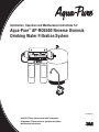
1
Installation, Operation and Maintenance Instructions For:
Aqua-Pure® AP-RO5500 Reverse Osmosis
Drinking Water Filtration System
98-880043 0609
Installer: Please leave manual with homeowner.
Homeowner: Please retain for operation and future
maintenance instructions.
SAFETY INFORMATION
Read, understand, and follow all safety information contained in these instructions prior to installation and use of the AP-RO5500 Reverse Osmosis (RO) Drinking Water Filtration System.
Retain these instructions for future reference.
Intended use:
The Aqua-Pure® AP-RO5500 Reverse Osmosis Drinking Water Filtration System is intended for use in filtering
drinking water in residential locations and has not been evaluated for other uses. The system is typically installed
beneath or near a kitchen sink, and it is recommended that the installation be performed by a qualified installation
specialist or a licensed plumber.
EXPLANATION OF SIGNAL WORD CONSEQUENCES
WARNING
Indicates a potentially hazardous situation, which, if not avoided, could result in
death or serious injury and/or property damage.
CAUTION
Indicates a potentially hazardous situation, which, if not avoided, may result in
property damage.
WARNING
To reduce the risk associated with choking:
• Do not allow children under 3 years of age to have access to small parts during the installation of this product.
To reduce the risk associated with eye, skin and respiratory and digestive tract burns from Calcium
Hypochlorite during installation:
• Calcium Hypochlorite (CAS 7778-54-3) granules are used for tank sanitation in this product.
•During installation, do not get in eyes or on skin or clothing. Do not ingest. Wear eye and face protection. Keep out of reach of children.
•For further safety information, refer to MSDS documents available at CHEMTREC (1-800-262-8200) or
www.3M.com.
To reduce the risk associated with ingestion of water contaminated with Calcium Hypochlorite sanitizer:
• After installation, sanitizer must be flushed from the system before first use as directed within the installation
instructions.
To reduce the risk associated with ingestion of contaminants:
• Do not use with water that is microbiologically unsafe or of unknown quality without adequate disinfection before or after the system.
To reduce the risk associated with a hazardous voltage due to an installer drilling through existing electric wiring or water pipes in the area of installation:
• Do not install near electric wiring or piping which may be in the path of a drilling tool when selecting the
position to mount the filter bracket.
1
CAUTION
To reduce the risk associated with property damage due to water leakage:
• Read and follow Use Instructions before installation and use of this system.
• Installation and Use MUST comply with all state and local plumbing codes.
• Protect from freezing. Drain filter when temperatures drop below 40°F (4.4°C).
• Do not install if water pressure exceeds 125 psi (862 kPa). If your water pressure exceeds 125 psi, you
must install a pressure limiting valve. Contact a plumbing professional if you are uncertain how to check
your water pressure.
• Do not install where water hammer conditions may occur. If water hammer conditions exist you must install a
water hammer arrester. Contact a plumbing professional if you are uncertain how to check for this condition.
• The system must be installed on COLD water lines only, maximum temperature is 100°F (37.8°C).
•The system must be installed with the inlet and outlet ports as labeled. Make sure not to reverse connections.
• The disposable filter cartridge must be replaced every six months or at the specified service cycle.
• Do not use a torch or other high temperature sources near filter or plastic fittings.
• Do not install in direct sunlight.
• Do not install near water pipes which will be in path of a drilling tool when selecting the position to mount
the bracket.
• Mount filter in such a position as to prevent it from being struck by other items used in the area of installation
(waste baskets, etc).
• On plastic fittings, never use pipe sealant or pipe dope. Use thread sealing tape only.
• Ensure all tubing and fittings are secure and free of leaks.
• Do not install unit if collet is missing. Contact CUNO if collets are missing from any fittings.
•SHUT OFF FUEL SUPPLY TO WATER HEATER after water is shut off.
• Shut off inlet water supply and depressurize system as shown in manual when changing cartridges or servicing.
IMPORTANT NOTES
•Failure to follow instructions may void warranty.
•Allow a minimum of 7 1/2” (19.5 cm) clear space under filter to facilitate cartridge change.
• Do not crimp copper tubing.
• Some state and local plumbing codes may prohibit the use of saddle-type valves and/or drain connections. The use of saddle-type valves are prohibited in: Alaska, Delaware, Idaho, Kentucky, Massachusetts, Michigan, Minnesota, New Hampshire, North Dakota, Ohio, Oregan and South Dakota. Check your local plumbing codes for any restrictions that apply.
•It is mandatory that safety glasses be worn during sink hole drilling operations to prevent eye injury.
2
Installation, Operation and Maintenance Manual
Introduction
This manual explains installation and operation of the Aqua-Pure® AP-RO5500 Reverse Osmosis (RO) Drinking
Water Filtration System. Please read each section of this manual carefully.
The Aqua-Pure AP-RO5500 RO Drinking Water Filtration System is designed to connect permanently to a home
plumbing system. To ensure that the installation conforms to your state and local plumbing codes, it is recommended
that the installation be performed by a qualified installation specialist for RO drinking water filtration systems or a
licensed plumber.
IMPORTANT NOTES
• Failure to follow instructions may void warranty.
The RO module is shipped with a preservative solution. Make sure that you flush the system thoroughly as directed before the first use.
NOTE: Make sure that the Owners Warranty Record Card is filled out and mailed within 10 days of installation.
Installation Checklist and Table of Contents
1.Determine System Location.
Determine System Location
......................................................................................................................
4
2.Prepare the Area for Installation.
Prepare the Area for Installation
................................................................................................................
4
3.Prepare the Filtration System for Installation.
.Prepare
...........................................................................................
the Filtration System for Installation
4
4.Install the Feed Water Valve and Tubing.
Install
....................................................................................................
the Feed Water Valve and Tubing
5
5.Prefill and Sanitize the Storage Tank.
Prefill and Sanitize the Storage Tank
.........................................................................................................
5
6.Install the Drain Connection.
......................................................................................................................
Install the Drain Connection
6
7.Install the Faucet.
.......................................................................................................................................
Install the Faucet
6
8.Make the Faucet Mounting Hole.
Make the Faucet Mounting Hole
................................................................................................................
7
9.Mount the Faucet.
.Mount
.....................................................................................................................................
the Faucet
8
10.Make Initial Faucet Tubing Connections.
Make Initial Faucet Tubing Connections
....................................................................................................
8
11.Install the Purification Assembly and Storage Tank.
Install the Purification Assembly and Storage Tank 9
...................................................................................
12.Make Final Tubing Connections.
Make
. ...............................................................................................................
Final Tubing Connections
9
13.Install Icemaker Hookup (optional).
Install Icemaker Hookup (optional)
..........................................................................................................
10
14.Install Filter Cartridges.
Install Filter Cartridges
............................................................................................................................
10
15.Start Up the System.
................................................................................................................................
Start Up the System
10
16.Installation Troubleshooting.
Installation Troubleshooting
.....................................................................................................................
11
17.Maintenance.
............................................................................................................................................ 12
Maintenance
18.Parts List.
.Parts
................................................................................................................................................
List
14
19.Installation Diagrams (Figures 1-6).
.Installation
........................................................................................................
Diagrams (Figures 1-6)
15
20.Limited One Year Warranty.
Limited
......................................................................................................................
One Year Warranty
18
3
Installation, Operation and Maintenance Manual
1. Determine System Location (see Figures 1 and 2)
Installation, Operation and Maintenance Manual
4. Install the Feed Water Valve and Tubing (see Figure 3)
The Drinking Water Filtration System can be located under a sink or in a basement depending on space availability and preference. If a basement installation is selected, additional tubing, hardware and fittings may be
needed and a hole will have to be made from inside the cabinet, through the floor, to the basement.
14 5/8" NOM
Space Requirements
NOTE: Never install the filtration system in an area of the home
where the temperature may drop to freezing as damage to the
system will result.
The exact placement of the various components of the filtration
system will vary from installation to installation. The installer must
decide on where to place the faucet, tank and purification assembly
by balancing convenience with ease of installation and servicing.
6 1/2"
14 1/8" NOM
CAUTION
To reduce the risk associated with property damage due to
water leakage:
• Protect from freezing. Drain filter when temperatures drop below
40°F (4.4°C).
• Do not install if water pressure exceeds 125 psi (862 kPa). If
your water pressure exceeds 125 psi, you must install a pressure limiting valve. Contact a plumbing professional if you are
uncertain how to check your water pressure.
1 1/2"
Minimum Distance
Required To Remove
Cartridges
Considerations for an icemaker or other remote hookup should be predetermined, including plumbing routing and any additional tools, fittings and tubing that may be required.
Feedwater Conditions
Parameter
pH
4-11
Manganese
< 0.05 ppm (mg/L)
Hardness
< 350 ppm (mg/L)
Hydrogen Sulfide
None allowable
Iron (FE)
< 0.3 ppm (mg/L)
Organics
< 1 ppm (mg/L)
Free Chlorine
Up to 3 ppm (mg/L)
Temperature
40-100°F (4-38°C)
Turbidity
< 1 NTU
TDS
Up to 2,000 ppm
Min./Max. Feedwater pressure 40-100 psi (276-690 kPa)
2. Prepare the Area for Installation
Determine where components will be located and how they will be mounted. Special mounting brackets
and hardware may be necessary to secure the system to a wall or ceiling joists if a basement installation is
called for. Inspect the cold water supply line and drain to determine if any additional fittings are required.
NOTE: It is a good idea at this time to check the condition of the undercounter plumbing for any existing or
potential leaks.
3. Prepare the Drinking Water Filtration System for Installation
Open the shipping carton and remove components. Check that all of the installation parts are present which
include the reverse osmosis (RO) assembly, storage tank, faucet, installation hardware, and tubing located
in box under storage tank.
If an optional percent rejection monitor is used, the probes should be installed at this time. Follow the instructions that come with the monitor.
4
The feed water saddle valve is designed for use with 3/8” to 1/2” OD soft copper tubing (plain or chromed) and
rigid metal pipe. Do not use with flexible ribbed supply tubing or plastic pipe which require special hardware.
Soft Copper Tubing Installations:
A) Turn off cold water valve under the sink, or the main water supply valve for the house.
B) Before installing feed water saddle valve, make sure piercing lance does not protrude beyond rubber
gasket. See instructions on bag.
C) Assemble both halves of feed water saddle valve on copper tubing.
D) For 3/8” O.D. tubing, use bracket with side projections to prevent distortion of tubing. Use “V” side of bracket for
all larger size tubing. Tighten screws evenly and firmly — brackets should be parallel. Do not deform tubing.
E) To pierce soft copper tube, turn handle to the right until it is firmly seated. The valve is closed in this position.
F) Turn on main supply valve to pressurize cold water line. Check for leaks. If valve stem leaks, tighten
nut/seal with a wrench.
G)Connect length of orange 1/4” tubing to feed water valve, using brass compression nut, insert and plastic sleeve (refer to Figure 3).
IMPORTANT NOTES
• Some state and local plumbing codes may prohibit the use of saddle-type valves and/or drain connections. See
page 2 for list of states. Optional feed valve assemblies can be purchased. See page 15 for further information.
Rigid Metal Pipe Installations:
A) Turn off cold water supply valve and drain the line to prevent spillage.
B) Drill 3/16” hole at the desired location. To prevent shock hazard, use a battery operated drill.
C) Turn valve handle to the right to expose piercing lance beyond the rubber gasket no more than 3/16”.
D) Assemble saddle valve on the supply pipe by screwing the two halves together. Use the “V” side of the
bracket. Tighten screws evenly and firmly, keeping the two sides of the bracket parallel.
E) Turn saddle valve handle to the right to close valve. If valve stem leaks, tighten nut/seal around valve
stem, with a wrench.
F) Connect length of 1/4” orange tubing to the feed water valve, using brass compression nut, insert and
plastic sleeve (refer to Figure 3).
NOTE: For basement installations, a longer length of orange feed water tubing may have to be used.
5. Prefill and Sanitize the Storage Tank
Prefilling the tank is always recommended so there is pressure to check for leaks and water to flush the
carbon filters. Tanks are furnished with a special disinfection capsule which sanitizes the tank when it is
filled with water. It is important to use a sanitizer when prefilling tank so the solution can sanitize the tubing,
fittings and faucet at the time of installation and startup.
WARNING
To reduce the risk associated with eye, skin and respiratory and digestive tract burns from Calcium Hypochlorite during installation:
• Calcium Hypochlorite (CAS 7778-54-3) granules are used for tank sanitation in this product.
•During installation, do not get in eyes or on skin or clothing. Do not ingest. Wear eye and face protection. Keep
out of reach of children.
•For further safety information, refer to MSDS documents available at CHEMTREC (1-800-262-8200) or www.3M.com.
A) Place tank on stand.
B) Remove the soft rubber cap from the tank inlet fitting.
C) Wrap PTFE tape to the right (clockwise) onto threads.
D) Pour sanitizer into tank.
5
Installation, Operation and Maintenance Manual
Installation, Operation and Maintenance Manual
5. Prefill and Sanitize the Storage Tank (continued)
8. Make the Faucet Mounting Hole
E) Thread ball valve onto tank.
F) Insert one end of 3/8” yellow tubing into ball valve.
G)Connect supplied 3/8” x 1/4” adaptor to other end of yellow tubing.
H) Connect free end of orange feed water tubing to 1/4” side of adaptor.
I) Open feedwater valve and tank valve and allow tank to fill (about 3 minutes).
J) To open feedwater valve, turn handle to the left (counterclockwise).
K) Turn off feedwater valve and tank valve.
L) Remove orange tubing from adaptor then remove adaptor from yellow tubing. The tubing may need to
be cut for removal due to line pressure. Refer to Figure 6.
M)Set tank aside for at least 15 minutes for disinfection.
6. Install the Drain Connection (Figure 4)
For basement installations, the drain saddle is generally not used. Instead, the RO reject line is routed so
that it drains into a laundry sink, floor drain or standpipe through an approved air gap.
Undercounter Installations:
IMPORTANT NOTES
• Before starting the undercounter installation procedure, inspect the condition of the drain piping, especially in
older homes where the traps and tailpieces can be deceptively thin and frail.
• Some state and local plumbing codes may prohibit the use of saddle-type valves and/or drain connections. See
page 2 for list of states. Optional feed valve assemblies can be purchased. See page 15 for further information.
The drain saddle assembly is designed to fit around a standard 1 1/2” O.D. drain pipe. For smaller (lavatory
type) or larger (ABS pipe) drains, consult your Aqua-Pure® distributor.
NOTE: The drain saddle should always be installed above (before) the trap and on the vertical or horizontal
tailpiece. Never install the drain saddle close to the outlet of a garbage disposal or dishwashing drain because plugging of the RO drain line may occur.
IMPORTANT NOTES
• It is mandatory that safety glasses be worn during sink hole drilling operations to prevent eye injury.
Before starting the hole making operation, always check below the sink so that nothing interferes with
mounting the faucet such as reinforcing ribs, support brackets or cabinet construction.
Stainless Steel Sink, faucet with or without air gap module.
Recommended Tools:
• Center punch
• Variable speed drill and high speed drill bits
• Greenlee chassis punch 7/8” hole size
(alternate 9/16” size may be used for faucets without air gap module)
• Protective gloves
Procedure:
A)Center punch a small indent at the desired faucet location.
B)Slowly drill the required pilot hole for the chassis punch.
C)Set up the chassis punch per instructions and tighten nut to cut the desired hole size.
D)Clean up sharp edges with a file if necessary.
Porcelain/Enamel/Ceramic on sheet metal or cast iron base;
faucet with or without air gap module:
Recommended Tools:
• Variable speed drill
• Relton porcelain cutter set 7/8” size
(alternate 9/16” porcelain bit may be used for faucets without air gap module)
• Plumbers putty
A) Position threaded half of drain saddle at selected location and mark the spot through the opening.
Procedure:
B) Drill a 1/4” hole at the marked spot through one side of drain tailpiece.
It is important to understand what is involved in this procedure. First, the glassy layer of porcelain must be
penetrated through to the base metal. Second, a center disc of porcelain must be removed while protecting
the surrounding porcelain against chipping or fracturing. Third, the base metal must be drilled through to
complete the hole.
C) Position both halves of drain saddle on drain pipe so the threaded opening lines up with the hole in the
drain pipe.
D) Use bolts and nuts to clamp drain saddle onto drain pipe. Do not overtighten and make sure that there is
equal space between saddle halves on each side. CAUTION: Overtightening could result in a cartridge
crack, which may lead to fluid leaking.
E) Wrap PTFE tap on thread of drain saddle elbow and tighten into drain saddle. Orient elbow in the direction of RO faucet location.
IMPORTANT NOTES
• Always operate drill with light pressure at slow speed (300-400 rpm).
• When using a porcelain cutter, it is critical to take the precaution that it is always in a sharpened condition. Dull
cutters are known to chip sinks.
A)Mark the center for the 7/8” hole.
7. Install the Faucet
NOTE: Undercounter installations require a faucet with faucet air gap module. See Figures 1 and 2.
A wide variety of RO faucet mounting situations can be encountered, the most common being stainless
steel and ceramic on metal sinks.
The faucet should be positioned so that it empties into the sink and the spout swivels freely for convenience.
If the sink already has a hole provided that can accommodate the RO faucet, then no drilling is required and
you can proceed to the section on mounting the faucet.
NOTE: Sprayers can be disconnected to provide a suitable hole for the RO faucet. A pipe cap or plug will
be required to seal the sprayer connection on the existing faucet.
6
B)Form a shallow putty dam around hole area and fill with enough water to lubricate carbide drill bit.
C)Carefully drill pilot hole through porcelain/enamel and base metal using carbide type pilot drill.
D)Insert pilot tip of spring loaded porcelain cutter into pilot hole.
E)Drill porcelain/enamel using spring loaded porcelain cutter, making certain a complete ring has been
cut through the porcelain/enamel to the base metal.
F) Change to the metal cutter. With slow speed and light pressure, cut away the inner porcelain/enamel
disc down to the base metal. Make certain that the cutter does not touch the outer rim of the cut porcelain/enamel. Continue with this bit to cut through metal until sink has been completely penetrated.
7
Installation, Operation and Maintenance Manual
Installation, Operation and Maintenance Manual
9. Mount the Faucet (see Figure 5)
11. Install the Purification Assembly and Storage Tank
IMPORTANT NOTES
• The Uniform Plumbing Code dictates that there must be an air gap between the RO reject line and the waste
drain. The faucet air gap module connections can be eliminated only if an air gap is provided elsewhere in the
drain line (i.e. basement installations).
WARNING
To reduce the risk associated with a hazardous voltage due to an installer drilling through existing electric
wiring or water pipes in the area of installation:
• Do not install near electric wiring or piping which may be in the path of a drilling tool when selecting the position
to mount the filter bracket.
Installation With Faucet Air Gap Module:
Undercounter Installation:
A)Familiarize yourself with all components shown in the air gap faucet diagram (Figure 5).
The RO assembly is usually mounted to the right or left sink cabinet sidewall, taking into consideration the
space available and the tank location. Generally, the tank is placed in the rear of the sink cabinet while the
purification assembly is positioned toward the front for better accessibility.
B)Slide stainless base plate and rubber washer up tube and brass threaded stem of faucet.
C)Connect length of standard green 1/4” tubing to smaller barb on air gap faucet. Push on firmly until it seats.
D)Connect length of black 3/8” tubing to larger barb on air gap faucet.
E)Feed both the green and black tubing and threaded nipple through sink/counter mounting hole and
orient the faucet.
F) From below sink/counter, assemble the white spacer (open end up, open side toward air gap), flat
washer and hex nut on threaded nipple and tighten by hand.
G)Back off on hex nut just enough to slide slotted washer between white spacer and underside of sink/
counter (with open side of slotted washer closest to air gap tubes.)
H)After rechecking faucet orientation, tighten hex nut (9/16” wrench) until faucet feels secure.
I) From above the sink, make any minor orientation corrections by turning the faucet with a padded adjustable wrench. NOTE: Flats on chrome faucet may be used for tightening with an adjustable wrench.
Use care not to mark chrome finish.
10. Make Initial Faucet Tubing Connections (see Figure 1)
A)The orange 1/4” tubing should have already been connected to the feedwater valve with 1/4” brass
compression nut, insert and plastic sleeve.
B)Connect the 3/8” x 1/4” adapter that was used to fill tank to the 1/4” blue faucet tube.
C)Route black 3/8” tubing from faucet air gap module to drain saddle so that it slopes continuously
downward without loops or low spots. Cut to proper length and connect to drain elbow by pushing
tubing into fitting. Refer to Figure 6. If basement installation, route standard green 1/4” tubing from an
appropriate drain connection (e.g. laundry sink, floor drain, stand pipe) to intended location of filtration
assembly. An air gap must be installed between outlet and drain connection.
CAUTION
To reduce the risk associated with property damage due to water leakage:
• Ensure all tubing and fittings are secure and free of leaks.
• Installation and Use MUST comply with all state and local plumbing codes.
• Do not install if water pressure exceeds 125 psi (862 kPa). If your water pressure exceeds 125 psi, you
must install a pressure limiting valve. Contact a plumbing professional if you are uncertain how to check
your water pressure.
• Do not use a torch or other high temperature sources near filter or plastic fittings.
• Mount filter in such a position as to prevent it from being struck by other items used in the area of installation
(waste baskets, etc).
• Shut off inlet water supply and depressurize system as shown in manual when changing cartridges or servicing.
8
To mount the RO assembly, elevate it at least 2” off the cabinet floor (with cartridges installed) and, while
keeping level, mark the location of the mounting holes on the cabinet sidewall. Make small pilot holes with
an awl or drill and screw in the two mounting screws, leaving just enough protruding to allow bracket mounting slots to slide over them.
NOTE: If the cabinet sidewalls are not of solid construction, the RO assembly can be set on the cabinet
floor and held against the sidewall with the mounting screws. However, the RO assembly will then need to
be lifted from the mounting screws in order to remove filter cartridges.
The tank can be oriented either vertically or horizontally. It is generally placed to the rear of the cabinet but
can be set in the from center (between the sink basins) for ease of access if space permits.
Basement Installation:
The RO assembly is generally mounted to the basement wall (using wall anchors) or to wood ceiling supports. To mount the RO assembly, keep bracket level and mark the location of the mounting holes. Install
wall anchors and/or mounting screws as required. Leave screw heads protruding to allow bracket mounting
slots to slide over them.
The tank may be oriented either vertically or horizontally and can be placed on a shelf, on the floor, or suspended from the ceiling supports using sturdy brackets.
An effort should be made to minimize the distance between the tank and RO assembly to help assure an
adequate flow rate to the faucet.
12. Make Final Tubing Connections (see Figure 1)
With all of the components in place, the final tubing connections can be made. When routing tubing between components, several guidelines should be observed.
Tubing runs should generally follow the contour of the cabinets rather than interfere with the cabinet storage area. Strive for neatness and an orderly tubing “flow” using fasteners (e.g. insulated staples) to secure
the tubing. Arrange the tubing so there are no sharp bends and leave some “play” in the tubing for ease of
servicing, then cut tubing to desired length.
Try to keep the tubing form the RO assembly to the tank and faucet as short as practical for good flow.
Undersink Installation:
A)Connect orange 1/4” tubing from feedwater valve to “Feed” connection on RO assembly.
B)Connect one end of blue 3/8” tubing to faucet adapter and the other end to the “faucet” connection on
the RO assembly.
C)Connect yellow 3/8” tubing from storage tank to the tee on the RO assembly.
D)Route special red “SFC” tube from RO assembly module (factory made connection) toward faucet. Do
not cut this special SFC tube. Its length is important to maintain proper efficiency and performance.
E)Remove white plug from coupling fitting on end of red SFC tube. Connect SFC tube to one end of 1/4”
x 1/4” coupling fitting.
F) Connect the green 1/4” tubing from faucet air gap to 1/4” coupling fitting on the end of SFC tube
(See Figure 5).
9
Installation, Operation and Maintenance Manual
Installation, Operation and Maintenance Manual
13. Install Icemaker Hookup (optional)
16. Installation Troubleshooting
The RO drinking water filtration system can be connected to any standard refrigerator icemaker or icemaker/water dispenser. It should never be connected to a commercial type bar icemaker.
Problem:
Hooking up an icemaker involves connecting a tee with shutoff valve into the blue 3/8” faucet tubing and
routing tubing over to the refrigerator. Hooking up to existing copper tubing is generally not recommended.
If copper tubing must be used, then installation of a small in-line carbon filter at the refrigerator connection
is recommended.
Causes:
CAUTION
To reduce the risk associated with property damage due to water leakage:
• Ensure all tubing and fittings are secure and free of leaks.
Before turning off the existing tap water supply to the refrigerator icemaker, always shut off the icemaker first
(usually by lifting the lever arm above the bin to the uppermost position). The icemaker should only be turned
on again after the RO system has been drained several times and the tank has a full supply of water.
IMPORTANT NOTES
• Before any service is performed on the RO system, always turn off the icemaker valve and the icemaker unit.
Only turn on when the system is operating and the tank is full.
NOTE: High capacity residential refrigeration icemakers (e.g. Subzero) may require a minimum pressure of
20 psi (138 kPa). In some instances, this unit will not provide 20 psi (138 kPa) or greater pressure. In that
case, a second storage tank will be required. Please call technical services for installation advice.
14. Install Filter Cartridges
Water leaks from opening in air gap module.
A)Drain line blocked or drain not drilled through completely.
B)Air lock in air gap outlet.
C)Drain line has loop or is not vertical enough.
Solutions:
A)Check that drain line is clear of obstructions and remove drain saddle fitting to verify that the hole is
drilled through completely.
B)Blow air into air gap outlet using short length of tubing.
C)Shorten tubing so that run is as vertical as possible.
Problem:
Noise in drain (“gurgling” or “dripping” sound)
Cause:
Reject water dripping into standing water in the drain trap.
Solutions:
A)Make sure the 3/8” black tubing from faucet air gap module slopes continuously downward to drain
saddle without loops or low spots.
B)Angle drain piping so reject water runs down side of drainpipe.
A)Remove new filter cartridges from the box.
B)Using tap water (or food grade silicone lubricant or glycerin), wet the o-ring seals to make insertion easier.
C)Line up the cartridge ears, insert cartridge and push into the head until fully seated. Twist the cartridge
1/4 turn to the right (clockwise) to lock into place.
C)Change location of drain saddle to horizontal drain pipe or alternate vertical drain pipe farther from the
trap. Properly plug original hole. CAUTION: Make sure drain saddle is always installed above (before)
the trap.
Problem:
System is not producing water.
15. Start Up The System
A)Double check that all connections are secure.
Cause:
B)Turn on feedwater saddle valve and check for leaks. If any leaks are noted, turn off valve and correct
before proceeding. NOTE: If a leak occurs at a “Push-In” fitting, refer to Figure 6.
B)Too little or no reject water.
A)Need a minimum of 40 psi (276 kPa) incoming water pressure.
C)Incorrect tank pressure.
C)Lift faucet handle and allow tank to drain completely of sanitizing solution. Do not use this water. When
tank is empty, the faucet will steadily drip. This is the rate water is processed by the RO system. Approximately 2-3 drops per second.
Solutions:
D)Close faucet. Wait at least 4 hours and drain tank again. The water should be discarded as it may contain some disinfectant solution.
B)Disconnect special SFC reject tubing from faucet air gap inlet tubing and check reject flow rate which
should be approximately 175 ml/min.
E)The system should be ready to use as soon as the tank refills. If any objectionable taste is noticed after
the second tank draining, wait and drain tank the following day. Only when the tank is full should an
icemaker be turned on if one is connected to the system.
C)Empty water from tank. Lift tank to verify that it is empty. Adjust pressure to 5-7 psi (34-48 kPa).
WARNING
To reduce the risk associated with ingestion of water contaminated with Calcium Hypochlorite sanitizer:
• After installation, sanitizer must be flushed from the system before first use as directed within the installation
instructions.
NOTE: When the system is first turned on, water may intermittently “spurt” from the air gap module. This is
perfectly normal and is caused by air trapped in the system. This will usually disappear within a short time.
10
A)Increase pressure by adding pressure pump.
Problem:
System is not producing enough water.
Cause:
Incorrect tank pressure.
Solutions:
Empty water from tank. Lift tank to verify that it is empty. Adjust pressure to 5-7 psi (34-48 kPa).
11
Installation, Operation and Maintenance Manual
17. Maintenance
Installation, Operation and Maintenance Manual
How to Replace the Membrane Module
Reverse Osmosis drinking water filtration systems contain treatment components that are critical for effective reduction of Total Dissolved Solids as well as inorganic chemical contaminants. We strongly recommend that the user test the water periodically (every six months minimum) to verify that the system is performing satisfactorily. A Percent Rejection (PR) Water Quality Monitor is available to provide the user with
a means to test the water at any time. Routine maintenance is necessary in the form of prefilter, postfilter
and membrane replacement.
Replacing Filter Cartridges
The life of filter cartridges generally depends on local water conditions (i.e., dirt, rust and/or chlorine levels)
and by the length of service.
CAUTION
To reduce the risk associated with property damage due to water leakage:
• The disposable filter cartridge must be replaced every six months or at the specified service cycle.
When to Replace Filters
A)Every six months, or at the specified service cycle.
B)A noticeable decrease in water production is an indication that the filters require changing.
Replacement of the RO module generally requires:
New replacement membrane module of the same type and performance and supplies for sanitizing.
A)Open faucet, shut off tank and turn off feedwater. Wait five minutes for RO assembly to completely
depressurize.
B)Disconnect tubing from all three connections on membrane module (refer to Figure 6). Please note
the tube color and respective fitting for re-connection.
C)Remove RO membrane module from clips and discard.
D)Position replacement module above clips and push into place. If necessary, rotate module so fittings
are aligned with respective tubing.
E)Insert each tubing end into respective “Push In” connector as far as it will go. Refer to Figure 6. Please
note that the blue tubes attach to center fittings on module.
F) Follow the sanitizing and start up procedures for the storage tank and purification assembly outlined in
the next section.
Sanitizing The RO Filtration System
For the highest quality water from your Aqua-Pure® RO drinking water filtration system, it is important to
routinely sanitize both the storage tank and the RO assembly.
C)A decrease in water quality would be an indication.
How to Replace Prefilter and Postfilter Cartridges
A)Shut off feedwater saddle valve and tank valve. Open faucet to relieve pressure then close. Wait approximately 10 seconds for the water pressure to depressurize.
B)Twist the filter cartridge 1/4 turn to the left (counterclockwise) so that the ears on the cartridge are
able to disengage from the head. Then pull cartridge from the head. (It may be necessary to twist the
cartridge slightly from side to side to help free it.)
C)Remove new filter cartridges and the sanitary sealed wrapper from the box. Double check to see that
it is the correct replacement filter cartridge by comparing the labels.
D)Using tap water (or food grade silicone lubricant or glycerin), wet the o-ring seals to make insertion
easier.
E)Line up the cartridge ears, insert cartridge and push into the head until fully seated. Twist the cartridge
1/4 turn to the right (clockwise) to lock in place.
F) Turn on the feedwater and allow storage tank to fill completely (approximately 6 - 8 hours). Carefully
check for leaks.
H)Open faucet and empty storage tank to drain.
Replacing RO Membrane Module
The life of the RO membrane depends on local water chemistry and proper maintenance, e.g., regular filter
changes. Under typical conditions, the RO membrane life ranges from eighteen (18) months to three (3)
years because of its self cleaning feature.
The RO membrane should be replaced as determined by an optional percent rejection (PR) monitor. The
monitor is factory preset so that a green light will be displayed when the water quality is good, and a red
or yellow light indicates that replacement may be necessary. If a red or yellow light is displayed, the faucet
should be opened and the storage tank drained. After it has refilled, check the system again. If a red or yellow light is still displayed, the membrane should be replaced.
Recommended service life of the RO membrane is 36 months, maximum.
12
IMPORTANT NOTES
• The sanitizing procedures are intended to be part of a routine maintenance program only and not designed to
sanitize systems that have become highly contaminated from misuse.
When to Sanitize the Storage Tank
A)Upon start-up as described in Section 5 of the Installation Manual. NOTE: Standard Aqua-Pure RO
storage tanks need a special sanitizing agent which is activated when the storage tank is initially filled.
(See Section 5 in the Installation Manual.)
B)After any servicing or routine maintenance which involves the prefilter(s) or membrane.
C)After any extended period of non-use (over 30 days) unless cartridges are stored in a sealed plastic
bag in a refrigerator.
Refer to Section 5 Steps D through K to Sanitize Storage Tank.
How to Sanitize the RO Assembly
Sanitizing the RO Assembly generally requires:
• New pre and post cartridge
• Common household bleach (5.25% NON-scented)
• Standard eyedropper or equivalent
A) Shut off feedwater valve and tank ball valve.
B)Follow instruction of changing prefilter.
C)Before attaching new cartridge(s), use eye dropper to inject one teaspoonful (approximately 5 ml) of
household bleach into the center of each filter cartridge.
D)Turn on feedwater valve and tank ball valve.
E)Open faucet to allow tank to drain.
F) Close faucet valve and allow system to run for at least one hour.
G)Drain tank and discard water. NOTE: If any objectionable taste is noticed, drain tank again and allow
to refill.
H)Allow the system to run into the sink for the remainder of 24 hours to flush the membrane.
I) Close faucet. The filtration system should be ready to use as soon as the tank refills.
13
Installation, Operation and Maintenance Manual
Installation, Operation and Maintenance Manual
Long Term Non-Use
General Undercounter Installation Schematic (Figure 1)
If the RO filtration system is left unused for long periods (>30 days), follow this procedure:
A)Open faucet to drain tank and turn off feedwater valve. Wait five minutes for RO assembly to depressurize.
Faucet with
Air Gap
Faucet with
For best flow, tubing must
Air Gap
B)Remove all cartridges. Turn cartridges upside down in sink or container to drain out as much water as
possible.
C)Place cartridges in a plastic bag with air tight seal and store in refrigerator. Cartridges must not be allowed to freeze or permanent damabe may occur.
be as vertical as possible.
For best flow, tubing must
be as vertical as possible.
1/4” Green
D)When RO filtration system is ready to be put into service, reinstall cartridges in the RO assembly
heads and sanitize storage tank as described in Section 4. The RO assembly can also be sanitized at
this time, if desired.
3/8” Yellow
3/8” Black
Red SFC Tubing
3/8” Yellow
Red SFC Tubing
3/8” Yellow
3/8” Blue
1/4” Orange
Sink
Drain
Sink
Drain
RO
Assembly
RO
18. Parts List
Cold Water
Supply Only
Cold Water
Supply Only
1/4” Orange
3/8” Blue
E)Follow start up procedure outlined in Section 4.
3/8” Yellow
3/8” Black
1/4” Green
Assembly
For best flow, keep
tubing from Tank
For best flow, keep
to RO Assembly as
tubing from Tank
short as possible.
to RO Assembly as
short as possible.
Storage
Tank
Storage
Tank
General Basement Installation Schematic (Figure 2)
Faucet without
Air Gap
Faucet without
Air Gap
1
Undersink Area
Undersink Area
3/8” Blue
Floor
3/8” Blue
Floor
3/8” Yellow
3/8” Yellow
Red SFC Tubing Cold Water
Supply Only
Red SFC Tubing Cold Water
Supply Only
4
1/4” Green
1/4” Orange
3
RO
Assembly
RO
Assembly
2
1/4”
Green
Air gap
device
(eg. Gap-A-Flow)
Air gap device
(eg. Gap-A-Flow)
1/4” Orange
For best flow, keep
tubing from Tank
For best flow, keep
to RO Assembly as
tubing from Tank
short as possible.
to RO Assembly as
short as possible.
Storage Tank
Storage Tank
Sink
Drain
Sink
To laundry sink
standpipe or floor
To laundry sink
drain
standpipe or floor
drain
Drain
Feedwater Valve Installation (Figure 3)
Item No.
Description
Part No.
1
RO Module
56084-01
2
Replacement Cartridges
55981-01
3
Shut Off Valve
60-90119
4
SFC Tubing
52-318212
nut/seal
• Some state and local plumbing codes may
prohibit the use of saddle-type valves and/or
drain connections. The use of saddle-type
valves are prohibited in: Alaska, Delaware,
Idaho, Kentucky, Massachusetts, Michigan,
Minnesota, New Hampshire, North Dakota,
Ohio, Oregan and South Dakota. Check
your local plumbing codes for any restrictions
that apply.
plastic sleeve
compression nut
piercing
lance
For 3/8” OD tubing use side of
bracket with projections
AP5500
Line Art
14
IMPORTANT NOTES
insert
1/4” orange
feed water
tubing
For 7/16” - 1/2” OD tubing or rigid
pipe use “V” side of bracket
15
Installation, Operation and Maintenance Manual
Installation, Operation and Maintenance Manual
Drain saddle elbow
Drain Connection Instalaltion (Figure 4)
NOTES:
Hole should be
located on top
of the pipe
Drain saddles
Garbage
Disposal
NEVER mount here
Mount drain saddle at
either location
Drain Connection
(horizontal example)
Faucet Installation (Figure 5)
Side View
Back View
Air gap hole
Base plate
C.L.
Rubber washer
Slotted washer
1/4" Standard green tubing
Spacer
Threaded nipple
Special red "SFC"
tubing from RO
Flat washer
Hex nut
Black 3/8" Reject tubing to drain
Blue 1/4” Product
water tubing
Blue 1/4" Product water tubing
3/8" Tubing from storage tank
How to Use “Push In” Connectors (Figure 6)
How to Use “Push In” Connectors
To Attach Tubing
1 Tube
To Release Tubing
1
2
2
Grey Collet
Push tubing straight in as far as it will go. Tubing must be inserted past o-ring and
hit backstop. Pull tube to ensure it is secured.
Push in grey collet to release tubing. With collet held, pull tubing straight out.
CAUTION
To reduce the risk associated with property damage due to water leakage:
• Ensure all tubing and fittings are secure and free of leaks.
• Do not install unit if collet is missing. Contact CUNO if collets are missing from any fittings.
This product is equipped with user-friendly “Push In” connectors. Proper use of the connectors is shown in the diagrams.
It is most important that the tubing selected for use with the connectors be of high quality, exact size and roundness,
and with no surgace nicks or scratches. If it is necessary to cut the tubing, use a plastic tubing cutter or sharp razor
knife. Make a clean square cut. Should a leak occur at a Push In connector, the cause is usually defective tubing.
To fix: 1. Relieve pressure. 4. Reattach tubing.
2. Release tubing. 3. Cut off at least 1/4” from end.
5. Confirm connection is leak-free.
16
17
20. Limited One Year Warranty
CUNO Incorporated warrants the original purchaser-consumer of its Product that is free of defects in materials and
workmanship. Any defect, malfunction, or other failure of
the Product to conform to this warranty will be remedied by
CUNO in the manner provided below.
This Warranty, together with any warranties implied by law,
shall be limited to a duration of one (1) year from the original
date of purchase by the consumer.
This Warranty does not apply to defects that result from
abuse, misuse, alteration or damage not caused by CUNO.
IMPORTANT: To file a claim under this warranty you must
complete and mail the Warranty Registration Card supplied
with this product to CUNO at the address below within ten
(10) days of original purchase date.
THIS WARRANTY DOES NOT COVER, AND IS INTENDED TO EXCLUDE ANY LIABILITY ON THE PART OF
CUNO, WHETHER UNDER THIS WARRANTY OR UNDER
ANY WARRANTY IMPLIED BY LAW, FOR ANY INDIRECT
OR CONSEQUENTIAL DAMAGES FOR BREACH HEREOF OR THEREOF.
Note: Some states prohibit limitations on the duration of
implied warranties and on the exclusion of indirect or consequential damages; and so the limitation on implied warranties and on incidental and consequential damages may not
be applicable to you.
RESPONSIBILITY OF CUNO
CUNO’s responsibility under this warranty shall be to repair at its expense, at no charge to the original purchaser-cosumer, any product that is actually defective, malfunctioning,
or otherwise in violation of this warranty. If CUNO for any
reason cannot repair a Product covered hereby within two
(2) weeks after receipt of the original purchaser-consumer’s
notification of a Warranty claim, then CUNO’s responsibility
shall be, at its option, either to replace the defective Product
with a comparable new unit at no charge to the consumer
or to refund the full purchase price. CUNO’s obligations of
repair, replacement, or refund are conditioned upon return of
the defective Product to CUNO.
If any Product covered hereby is actually defective within the
terms of this Warranty, then CUNO will bear all the reasonable and proper shipping and mailing charges actually incurred in the consumer’s return of the Product set forth herein. If the Product proves not to be defective within the terms
of this Warranty, then all costs and expenses in connection
with the processing of the consumer’s claim hereunder shall
be borne by the consumer.
RESPONSIBILITY OF THE CONSUMER
The original purchaser-consumer’s sole responsibility in
the instance of a warranty claim shall be to notify CUNO of
the defect, malfunction, or other manner in which the terms
of this Warranty are violated. You may secure:
1. Identifying the Product involved (by model or serial number or other sufficient description that will allow CUNO to
determine which product is defective).
2. Specifying where, when, and from whom the Product
was purchased.
3. Describing the nature of the defect, malfunction, or other violation of this Warranty.
4. Sending such notification together with the defective
Product and $5.00 check or money order to cover postage and handling to:
CUNO Incorporated, 400 Research Parkway
Meriden, CT 06450, USA
THIS WARRANTY GIVES YOU SPECIFIC LEGAL RIGHTS,
AND YOU MAY ALSO HAVE OTHER RIGHTS, WHICH
VARY FROM STATE TO STATE.
®
a 3M company
3M is a trademark of 3M Company.
CUNO and Aqua-Pure are trademarks of 3M Company used under license.
© 2009 3M Company. All rights reserved.
CUNO Incorporated
400 Research Parkway
Meriden, CT 06450 USA
Toll Free: 1-800-222-7880
Worldwide: 203-237-5541
Fax: 203-238-8701
www.aquapure.com • www.cuno.com