1
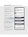
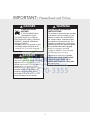
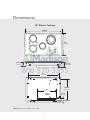
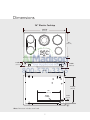
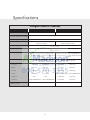
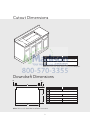
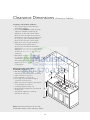
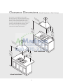
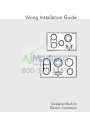
Viking Installation Guide
Designer Built-In
Electric Cooktops
Table of Contents
Warnings & Important Safety Instructions _______________________________________________3
Dimensions (30”) ____________________________________________________________________6
Dimensions (36”) ____________________________________________________________________7
Specifications _______________________________________________________________________8
Cutout Dimensions __________________________________________________________________9
Downdraft Dimensions ______________________________________________________________9
Clearance Dimensions (Proximity to Cabinets) ___________________________________________9
Clearance Dimensions (Wood/Composite or Steel Overlay) ______________________________11
Electrical Requirements _____________________________________________________________12
General Information ________________________________________________________________14
Installation _________________________________________________________________________15
Electrical Connection ____________________________________________________________16
Final Installation ________________________________________________________________16
Final Preparation ___________________________________________________________________17
Performance Checklist ______________________________________________________________17
Service & Registration _______________________________________________________________18
IMPORTANT– Please Read and Follow
• Before beginning, read these instructions
thoroughly and carefully.
Your safety and the safety of others is
very important.
We have provided many important safety
messages in this manual and on your
appliance. ALWAYS read and obey all
safety messages.
• Installation and service must be performed by
a qualified installer, service agency.
• DO NOT remove permanently affixed labels,
warnings, or plates from the product as this
may void the warranty.
This is the safety alert symbol. This
symbol alerts you to hazards that
can kill or hurt you and others.
• Observe all local and national codes,
requirements and ordinances.
All safety messages will be preceded by
the safety alert symbol and the word
“DANGER,” “WARNING” or “CAUTION.”
These words mean:
• Write down the model and serial numbers
before installing the cooktop. Both numbers
are on the serial rating plate located on
bottom of cooktop box.
DANGER
• Installation must conform with local codes or in
the absence of codes, the national electric
code: ANSI/NFPA 70-latest edition** or CSA
standards C22. 1-94, Canadian Electrical Code,
part No. 0-M91 - latest edition*** and all local
codes and ordinances.
Hazards or unsafe practices
which WILL result in severe personal
injury or death
WARNING
In Canada: Installation must be in accordance
with the current CAN/CGA B149.1 & 2 Gas
Installation codes and with the current CSA C22.1
Canadian Electrical Codes Part 1 and/or local
codes.
Hazards or unsafe practices
which COULD result in severe personal
injury or death
CAUTION
Hazards or unsafe practices which
COULD result in minor personal injury
or property damage.
Copies of the standards listed may be obtained
from:
** National Fire Protection Association One
Batterymarch Park Quincy, Massachusetts 02269
*** CSA International 8501 East Pleasant Valley
Rd. Cleveland, OH 44131-5575
All safety messages will identify the
hazard, tell you how to reduce the chance
of injury, and tell you what can happen if
the instructions are not followed.
• Installers should leave these instructions with
the consumer who should retain them for the
local inspector’s use and for future reference.
3
IMPORTANT– Please Read and Follow
DANGER
WARNING
FIRE/EXPLOSION
HAZARD
ELECTRICAL GROUNDING
INSTRUCTIONS
IF THE INFORMATION IN
THIS MANUAL IS NOT
FOLLOWED EXACTLY, A FIRE OR
EXPLOSION MAY RESULT CAUSING
PROPERTY DAMAGE, PERSONAL
INJURY, OR DEATH.
• DO NOT store or use gasoline or other
flammable vapors and liquids in the
vicinity of this or any other appliance.
The cooktop must be electrically grounded
in accordance with local codes or, in the
absence of codes, with the ANSI/NFPA
No. 70-latest edition. Installation should
be made by a licensed electrician. This
appliance is equipped with a three-prong
grounding plug for your protection against
shock hazard and should be plugged
directly into a properly grounded
receptacle. DO NOT cut or remove the
grounding prong from the plug.
CAUTION
For personal safety, this appliance
must be properly grounded. DO NOT
under any circumstances cut or
remove the third (ground) prong from
the power plug.
BURN HAZARD
The use of cabinets for storage above the
appliance may result in a potential burn
hazard. Combustible items may ignite,
metallic items may become hot and
cause burns. If a cabinet storage is to be
provided the risk can be reduced by
installing a range hood that projects
horizontally a minimum of 5” (12.7 cm)
beyond the bottom of the cabinets.
4
IMPORTANT– Please Read and Follow
WARNING
WARNING
This appliance shall not be used for
space heating. This information is based
on safety considerations.
SITE PREPARATION
It is recommended that a thorough site
inspection be conducted PRIOR to
unpacking and moving this appliance.
WARNING
It is the customer's responsibility to
contact a qualified electrical installer. To
assure that the electrical installation is
Adequate and in conformity with national
electrical code: ANSI/NFPA 70-latest
edition** or CSA standards C22.1-94,
Canadian Electrical Code, part No.0-M91
- latest edition*** and all local codes and
ordinances.
WARNING
THE CONDUIT IS 3 FEET LONG
The junction box must be located where it
will allow considerable slack in the
conduit for serviceability.
5
Dimensions
30” Electric Cooktop
30-3/4”
(78.1 cm)
21”
(53.3 cm)
3-1/8”*
4-1/4”
(7.9 cm)
(10.8 cm)
28”
(71.1 cm)
18-9/16”
12”
(47.2 cm)
(30.5 cm)
Power
conduit
*Note: Dimension includes screw head.
6
3-1/4”
(8.3 cm)
Dimensions
36” Electric Cooktop
36-3/4”
(93.4 cm)
21”
(53.3 cm)
3-1/8”*
4-1/4”
(7.9 cm)
(10.8 cm)
33-3/8”
(84.7 cm)
18-9/16”
(47.2 cm)
12”
(30.5 cm)
Power
conduit
*Note: Dimension includes screw head.
7
3-1/4”
(8.3 cm)
Specifications
Designer Electric Cooktops
Description
DETU200-4B
DETU260-5B
Overall width
30-3/4” (78.1 cm)
36-3/4” (93.3 cm)
Overall height (from top of
cooktop to bottom of conduit)
4-1/4” (10.8 cm)
Overall depth from rear
Cutout width
21” (53.3 cm)
28-3/4” (72.9 cm) min. to
29” (73.7 cm) max.
34” (86.4 cm) min. to
34-9/16” (87.8 cm) max.
Cutout height
3-1/8” (7.9 cm)
Cutout depth
19-1/4” (49.0 cm) min. to
19-5/8” (49.8 cm)
Electrical requirements
Maximum amp usage
3-wire, 240-208/120VAC/60Hz;
3-wire, 240-208/120VAC/60Hz;
40 amp connection. Unit is equipped with
60 amp connection. Unit is equipped with
No. 10 ground wire in conduit. Should be fused No. 10 ground wire in conduit. Should be fused
separately.
separately.
240V—35.0 amps (8.4 kw)
208V—30.3 amps (6.3 kw)
240V—45.0 amps (10.8 kw)
208V—40.0 amps (8.3 kw)
240V
1,800 watts
208V
1,350 watts
240V
1,800 watts
208V
1,350 watts
800 watts
600 watts
800 watts
600 watts
Left rear
1,800 watts
1,350 watts
1,800 watts
1,350 watts
Center
1,500 watts
1,125 watts
N/A
N/A
Surface element rating
Left front
Bridge
Right front
Right rear
Approximate
shipping weight
2,500/1,600/800 watts 1,875/1,200/600 watts
35 lb. (13.1 kg)
8
2,500/1,600/800 watts 1,875/1,200/600 watts
1,500 watts
1,125 watts
2,100 watts
1,575 watts
60 lb. (27.2 kg)
Cutout Dimensions
A
B
A
DETU200
DETU260
28-3/4” (72.9 cm) min. to
29” (73.7 cm) max.
34” (86.4 cm) min. to
34-9/16” (87.2 cm) max.
B
19-1/4” (49.0 cm) min. to
19-5/8” (49.8 cm) max.
Note: Based on 24” deep cabinet with 3/4” backsplash.
Downdraft Dimensions
E
F
D
C
A
B
C
B
D
DETU260 w/DIPR160
28-3/4” (73.0 cm)
34” (86.4 cm)
20-1/4” (51.4 cm)
27 (68.6 cm)
33” (84.0 cm)
2-1/4” (5.7 cm)
E
7/8” (1.9 cm)
7/8” (1.9 cm)
F
7/8” (1.9 cm)
7/8” (1.9 cm)
A
Note: Refer to the downdraft installation instructions.
9
DETU200 w/DIPR100
Clearance Dimensions
(Proximity to Cabinets)
Proximity to Side Cabinet Installation
• The cooktop may be installed directly to
existing base cabinets.
• The cooktop CANNOT be installed directly
adjacent to sidewalls, tall cabinets, tall
appliances, or other side vertical surfaces
above 36” (91.4 cm) high. There must be a
minimum of 6” (15.2 cm) side clearance from
the cooktop to such combustible surfaces
above the 36” (91.4 cm) counter height.
• Within the 6” (15.2 cm) side clearance to
combustible vertical surfaces above
36” (91.4 cm), the maximum wall cabinet
depth must be 13” (33.0 cm) and wall cabinets
within this 6” (15.2 cm) side clearance must be
18” (45.7 cm) above the 36” (91.4 cm) high
countertop.
• Wall cabinet above the cooktop must
be a minimum of 30” (76.2 cm) above the
countertop for a full width of the cooktop.
This minimum height requirement does not
apply if a rangehood is installed over the
cooking surface.
10
(33
in.
” mcm)
0
3 2
.
(76
(156” m
.2 in
cm .
)
.
in
m *
” m)
/2 c
-1 .8
1 (3
Note: Dimensions shown are for use with
combustible surfaces unless otherwise stated.
.
ax
” mcm)
3
1 .0
.
in
m )*
” m
/2 5 c
-1 3
2 (6.
Minimum Clearances from Adjacent
Combustible Construction
• Wall cabinets directly above the product must be
in.
minimum 30” (76.2 cm) above the countertop
”m )
18 .7 cm
• Sides—minimum 6” (15.2 cm)
(45
• Rear—minimum 1-1/2” (3.8 cm)
• From edge of cutout and front edge of
countertop 2-1/2” (6.35 cm)
• Within 6” (15.2) side clearance; wall cabinets
no deeper than 13” (33.0 cm)
• Countertop depth 25” (63.5 cm)
in.
” mcm)
• Overhead cabinet depth from rear maximum
6
3 1.4
(9
13” (33.0 cm)
• Side cabinet height from countertop
minimum 18” (45.7 cm)
Clearance Dimensions
The bottom of a standard hood should be
30” (76.2 cm) min. to 36” (91.4 cm) max. above
the countertop. This would typically result in the
bottom of the hood being 66” (167.6 cm) to
72” (182.9 cm) above the floor. These dimensions
provide for safe and efficient operation of the
hood. Refer to the range hood installation
instructions for additional information.
(Wood/Composite or Steel Overlay)
Wo
o
or d/Co
Ste mp
el O os
ver ite
lay
66
(16 ”mi
7.6 n.
c
72 to m)
”
(18 ma
2.9 x.
cm
)
Wo
o
or d/Co
Ste mp
el O os
ver ite
lay
66
(16 ”mi
7.6 n.
c
72 to m)
”
(18 ma
2.9 x.
cm
)
”
30 cm)
.2
(76
6” m)
.2 c
5
(1
Wall Installation
30
(76”min
.2 .
cm
36 to )
”
(91 ma
.4 x.
c
m)
Island Installation
11
”
24 cm)
.0
(61 or
”
27 cm)
.6
(38
30
(76”min
.2 .
cm
36 to )
”
(91 ma
.4 x.
cm
)
Electrical Requirements
Electrical Connections
DO NOT ground to a gas pipe. DO NOT have a
fuse in the grounding or neutral circuit. Fuse both
supply (phase) lines.
WARNING
ELECTRICAL SHOCK HAZARD
Disconnect power before servicing the
product. Failure to do so could result in
death or electric shock.
WARNING
Improper connection of aluminum house
wiring to the copper leads can result in a
serious problem.
WARNING
National Fire Protection Association
ELECTRICAL SHOCK HAZARD
The models may be powered at 240V or
208V.
Batter/march Park Quincy, Massachusetts 02269
A three-wire, single phase, 240 Volt 60 cycle
electrical system (properly circuit protected to
meet Local Codes of NFPA No.70) must be
provided. Unit must be properly grounded in
accordance with local wiring code. The chart
below recommends the minimum circuit protector
and wire size if the appliance is the only unit on
the circuit. If smaller sizes of wire are used, the
unit efficiency will be reduced and a fire hazard
may be created. It is advisable that the electrical
wiring and hookup be accomplished by a
competent electrician.
This cooktop does not require a neutral
connection. If the cooktop is to be completely
enclosed in a cabinet, feed the cooktop cable
through the opening in the cabinet. Make the
electrical connection following the appropriate
steps for your installation.
Your cooktop must be connected to the proper
electrical voltage and frequency as specified in
the table on the right.
Recommended Minimum
KW Rating on Circuit protection
in amperes
serial plate
Connect with copper wire only
If the house has aluminum wiring, follow the
procedure below:
1. Connect the aluminum wiring to the copper
wire by using special connectors designed
and Underwriters Laboratories-listed for
joining copper to aluminum. Follow the
electrical connector manufacturer's
recommended procedure.
2. Aluminum/copper connection must conform
with local codes and industry- accepted
wiring practices.
Wire Size
(AWG)
0-4.8
20
12
4.9-6.9
30
10
7.0-9.9
40
8
10.0-11.9
50
8
12.0-14.9
60
6
Be sure your appliance is properly installed and
grounded by a qualified technician. Ask your
dealer to recommend a qualified technician or
an authorized repair service. This cooktop does
not require a neutral connection. If the cooktop
Is to be completely enclosed In a cabinet, feed
the cooktop cable through the opening in the
cabinet. Make the electrical connection
following the appropriate steps for your
installation.
The flexible conduit (supplied) 3 feet long
(100 cm) located at the right rear of the cooktop
bottom box should be connected directly to
junction box. DO NOT cut the conduit. A U.L - or
CSA - listed conduit connector must be provided
at each end of the power supply cable (at the
cooktop and at the junction box.) A time delay
fuse or circuit breaker is recommended.
12
Electrical Requirements
This appliance is manufactured with a green
ground wire connected to the cooktop chassis.
After making sure that the power has been turned
off, connect the flexible conduit from the cooktop
to the junction box using a U.L. listed conduit
connector. The instructions provided below
present the most common way of connecting the
cooktops. Your local codes and ordinances, of
course, take precedence over these instructions.
Complete electrical connections according to
local codes and ordinances.
WARNING
ELECTRICAL SHOCK HAZARD
Frame grounded to neutral of appliance
through a link.
Grounding through the neutral conductor is
prohibited for new branch-circuit installations
(1996 NEC); mobile homes; and recreational
vehicles, or in an area where local codes prohibit
grounding through the neutral conductor.
3-Wire branch circuit
Where local codes allow the connection of ground
wire from the cooktop to the branch circuit neutral
wire (gray or white colored wire) proceed as follows.
1. If local codes permit, connect the green
GROUND wire from the cooktop to the
branch circuit neutral wire (gray or white
colored wire).
2. Connect the red and black leads from the
cooktop to the corresponding leads in the
junction box.
4-Wire branch circuit
1. Connect the green ground wire from the
cooktop to the ground wire in the junction
box (bare or green colored wire).
2. Connect the red and black leads from the
cooktop to the corresponding leads in the
junction box.
3. Connect the white wire from the cooktop to
the neutral (gray or white) wire in the
junction box.
4. Terminate and insulate the neutral (gray or
white colored wire) in the junction box.
13
Clearance Dimensions
Junction Box Location
WARNING
*
THE CONDUIT IS 3 FEET LONG
The junction box must be located where it
will allow considerable slack in the
conduit for serviceability.
Install junction
box so that it can
be reached
through the front
of cabinet.
*Note: Minimum from bottom of countertop
and adjacent right-side cabinet to top of
junction box.
General Information
• All wall coverings, countertop and cabinets
around the cooktop should withstand heat up
to 200°F (90° C).
• Keep appliance free from combustible materials,
gasoline, and other flammable vapors.
WARNING
ELECTRICAL SHOCK
HAZARD
The models may be powered
at 240V or 208V.
Installation Procedure
Remove packaging materials and literature package
from the cooktop before beginning installation.
Remove Installation Instructions from literature pack
and read them carefully before you begin.
Site Preparation
Note: It is recommended that a thorough site
inspection be conducted prior to unpacking and
moving this appliance.
WARNING
• Chamfer all exposed edges of decorative
laminate to prevent damage from chipping.
• Radius corners of cutout and file to Insure
smooth edges and prevent corner cracking.
Recommend 1/4“or 3/8“ diameter drill In each
corner.
• Rough edges, inside corners which have not
been rounded and forced fits can contribute to
cracking of the countertop laminate.
• Confirm available access to adequate power–
see electrical requirements.
• Be sure that the countertop for this appliance
is level and cut according to the cutout
requirements and dimensions–see cutout
requirements and dimensions.
DO NOT use an extension cord with this
appliance. Such use may result in fire,
electrical shock or other personal injury.
14
Installation
1
2
Optional Gasket
Peel away the plastic covering and place the gasket material
all the way around the burner flange.
IMPORTANT: Make sure the corners are covered
completely, leaving no air gaps.
Turn the cooktop upside down and place on the packaged
foam top. Note: Make sure there are no loose objects on
the cooktop before turning upside down.
IMPORTANT
3
For solid surface material installations
such as Surel™ and Corian®, consult with
solid surface manufacturer. Apply heat
reflective tape such as Scotch® Aluminum
Foil Tape #425 or #427 around the cutout
so that it folds over on the top and sides.
DO NOT wrap the tape underneath the
cooktop. Be sure the tape extends
beyond the outermost flange of the
cooktop. All corners should be covered
with tape.
Turn the cooktop over and place into countertop
opening.
15
Electrical Connection
WARNING
1a
3 wire
THE CONDUIT IS 3 FEET LONG
The junction box must be located where it
will allow considerable slack in the
conduit for serviceability.
Green
Neutral
Red
Black
Connect the red and black leads from the unit conduit
to the corresponding leads in the junction box.
Final Installation
4 wire
1b
1
Green
Neutral
Green
Red
Black
Connect the red, black, and green leads from the unit
conduit to the corresponding leads in the junction box.
Install screws into brackets to secure cooktop to
countertop.
16
Final Preparation
• New units are cleaned at the factory to remove
any visible signs of dirt, oil, grease, etc.
remaining from the manufacturing process.
Some stainless steel parts may have a plastic
protective wrapper which must be peeled off.
The cooktop should be washed thoroughly
with hot, soapy water and then rinsed and
wiped dry to remove these film residues and
any installation dust or debris before being
used for food preparation.
Performance Checklist
A qualified installer should carry out the following
checks:
h Check top surface elements
1. Glow red when turned on.
h Check hot surface indicator lights
1. Glow red when corresponding element is
hot.
Any adjustments necessary that are a result of
the installer not following instructions will be
the responsibility of the installer, dealer of the
end user of this product.
17
Service & Registration
Only authorized replacement parts may be used in performing service on the appliance.
All servicing should be referred to a qualified technician.
Contact Viking Range Corporation, 1-888-VIKING1 (845-4641), for the nearest service parts
distributor in your area or write to:
VIKING RANGE CORPORATION
PREFERRED SERVICE
1803 Hwy 82W
Greenwood, Mississippi 38930 USA
The serial number and model number for your appliance can be found by looking under the cooktop.
Record the following information indicated below. You will need it if service is ever required.
Model number ____________________________________________________________________________________
Serial number _____________________________________________________________________________________
Date of purchase __________________________________________________________________________________
Date installed ______________________________________________________________________________________
Dealer's name _____________________________________________________________________________________
Address ___________________________________________________________________________________________
These installation instructions should remain with the unit
for future reference.
18
Notes
________________________________________________________________________________________________________________________________________________________
________________________________________________________________________________________________________________________________________________________
________________________________________________________________________________________________________________________________________________________
________________________________________________________________________________________________________________________________________________________
________________________________________________________________________________________________________________________________________________________
________________________________________________________________________________________________________________________________________________________
________________________________________________________________________________________________________________________________________________________
________________________________________________________________________________________________________________________________________________________
________________________________________________________________________________________________________________________________________________________
________________________________________________________________________________________________________________________________________________________
________________________________________________________________________________________________________________________________________________________
________________________________________________________________________________________________________________________________________________________
________________________________________________________________________________________________________________________________________________________
________________________________________________________________________________________________________________________________________________________
________________________________________________________________________________________________________________________________________________________
________________________________________________________________________________________________________________________________________________________
________________________________________________________________________________________________________________________________________________________
________________________________________________________________________________________________________________________________________________________
________________________________________________________________________________________________________________________________________________________
________________________________________________________________________________________________________________________________________________________
________________________________________________________________________________________________________________________________________________________
________________________________________________________________________________________________________________________________________________________
19
®
Viking Range Corporation
111 Front Street
Greenwood, Mississippi 38930 USA
(662) 455-1200
For product information,
call 1-888-VIKING1 (845-4641)
or visit the Viking Web site at
vikingrange.com
F20700 EN
(100709J)