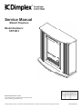
1
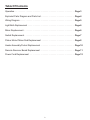
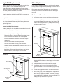
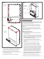
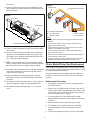
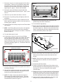
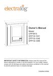
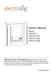
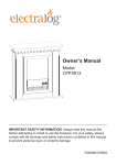
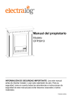
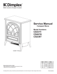
Service Manual
Mozart Fireplace
Model Numbers:
CFP3913
REV
00
PCN
DATE
11637 Sep 23, 09
Dimplex North America Limited
1367 Industrial Road Cambridge ON Canada N1R 7G8
1-888-346-7539 www.dimplex.com
In keeping with our policy of continuous product development, we reserve the right to make changes without notice.
7400270000rev00
Table Of Contents
Operation. . . . . . . . . . . . . . . . . . . . . . . . . . . . . . . . . . . . . . . . . . . . . . . . . . . . . Page 3
Exploded Parts Diagram and Parts List. . . . . . . . . . . . . . . . . . . . . . . . . . . . . . Page 4
Wiring Diagram. . . . . . . . . . . . . . . . . . . . . . . . . . . . . . . . . . . . . . . . . . . . . . . . Page 5
Light Bulb Replacement . . . . . . . . . . . . . . . . . . . . . . . . . . . . . . . . . . . . . . . . . Page 6
Mirror Replacement. . . . . . . . . . . . . . . . . . . . . . . . . . . . . . . . . . . . . . . . . . . . . Page 6
Switch Replacement. . . . . . . . . . . . . . . . . . . . . . . . . . . . . . . . . . . . . . . . . . . . Page 7
Flicker Motor/Flicker Rod Replacement . . . . . . . . . . . . . . . . . . . . . . . . . . . . . Page 8
Heater Assembly/Cutout Replacement. . . . . . . . . . . . . . . . . . . . . . . . . . . . . . Page 10
Remote Receiver Board Replacement . . . . . . . . . . . . . . . . . . . . . . . . . . . . . . Page 11
Power Cord Replacement . . . . . . . . . . . . . . . . . . . . . . . . . . . . . . . . . . . . . . . Page 12
2
Operation
Figure 2
Electric Fireplace Manual Control
The manual controls for the unit are located behind the
control panel on the front of the firebox (Figure 1). A switch
is in the ON position when the side with the markings on it
(i.e. I, or II) is pushed in.
Figure 1
On
Button
Battery
Off
Button
C
Control Panel
B
A
Battery Cover
Battery Installation/Replacement
1. Depress tab on the battery cover on the back of the
remote transmitter and remove battery cover (Figure 2).
2. Properly orientate and install one (1) 12 Volt (A23) battery
into the remote control.
3. Replace the battery cover.
Manual Control
Switches
A - 3 Position On/Off Switch
(I) Manual mode
Resetting The Temperature Cutoff Switch
Controls the electricity supply to the heater and flame
manually.
Should the fireplace overheat, an automatic cut out will turn
the heater off and it will not come back on without being
reset. It can be reset by switching Switch A (Figure 1 A) to
OFF and waiting five (5) minutes before switching the unit
back on.
(II) Remote mode
Allows the control of electricity supply to the heater and flame
through the use of the supplied remote control.
CAUTION: If you need to continuously reset the heater,
unplug the unit and call Dimplex North America Limited at
1-888-346-7539 for technical support.
! Note: This switch must be in the ON (I) position for
heater to operate with or without heat.
B - Low Heat Switch
(I) Provides 715 Watt heat output.
C - High Heat Switch
(II) Provides 1430 Watt heat output with Switch B.
! NOTE: If Switches B and C are in the off position, only
the flame effect will turn on when Switch A is activated.
Remote Control
The fireplace is supplied with an integral on/off remote
control.
! NOTE: Ensure that the fireplace’s 3 Position On/Off
Switch is set to the remote control setting (I.E.. II).
To operate: push ON button to turn fireplace on; push OFF
button to turn fireplace off (Figure 2).
! NOTE: Remote control operates main power supply. Heat
must still be controlled by switches on fireplace.
3
Exploded Parts Diagram
15
10
11
1
12
3
9
14
13
2
5
8
7
4
6
Replacement Parts List
CFP3913
Part Number
6904890100
Replacement Part:
1. Log set. . . . . . . . . . . . . . . . . . . . . . . . . . . 0439290100RP
2. Flicker Motor. . . . . . . . . . . . . . . . . . . . . . 2000210100RP
3. Flicker Rod . . . . . . . . . . . . . . . . . . . . . . . . 5901110100RP
4. Heater Assembly . . . . . . . . . . . . . . . . . . . 2200491000RP
5. Cutout. . . . . . . . . . . . . . . . . . . . . . . . . . . 2300270100RP
6. 3 Position On/Off Switch (I/O/II) . . . . . . . 2800071100RP
7. Low Heat Switch (I) . . . . . . . . . . . . . . . . . 2800070700RP
8. High Heat Switch (II). . . . . . . . . . . . . . . . 2800071000RP
9. Terminal Block (2 in unit) . . . . . . . . . . . . 4000120100RP
10.Cord Set . . . . . . . . . . . . . . . . . . . . . . . . . 4100090104RP
11. Mirror. . . . . . . . . . . . . . . . . . . . . . . . . . . . 5900980100RP
12.Front Glass . . . . . . . . . . . . . . . . . . . . . . . 5900930100RP
13.Lamp holder . . . . . . . . . . . . . . . . . . . . . . 4200090100RP
14.Remote Receiver. . . . . . . . . . . . . . . . . . . 3000380200RP
15.Remote Transmitter. . . . . . . . . . . . . . . . . 3000370800RP
4
Wiring Diagram
Remote
Receiver
Board
Flicker Motor
Low Heat Switch
High Heat
Switch
3 Position
On/Off Switch
Cutout
Cord Set
Power
Terminal Block
Heater Assembly
Circuitry
Terminal Block
Wire #
1.
2.
3.
4.
5.
Colour
Yellow
Grey
Grey
Grey
Blue
6.
7.
8.
9.
10.
Red
Blue
Red
Red
Black
11.
12.
13.
14.
15.
Black
Blue
Black
Blue
Blue
5
16.
17.
18.
19.
Red
Grey
Blue
Blue
Light Bulb Replacement
Mirror Replacement
Allow at least five (5) minutes for light bulbs to cool before
touching bulbs to avoid accidental burning of skin.
If the fireplace was operating prior to servicing allow at least
five (5) minutes for light bulbs and heating element to cool off
to avoid accidental burning of skin.
Light bulbs need to be replaced when you notice a dark
section of the flame. There are two (2) bulbs behind the log
set which generate the flames and embers.
Disconnect power before attempting any maintenance or
cleaning to reduce the risk of electric shock or damage to
persons.
Disconnect power before attempting any maintenance or
cleaning to reduce the risk of electric shock or damage to
persons.
Replacement Procedure
Helpful Hints
1. Pull fireplace away from the wall far enough to access
the back of the unit.
It is a good idea to replace all light bulbs at one time if they
are close to the end of their rated life. Group replacement
will reduce the number of times you need to open the unit to
replace light bulbs.
2. Remove one (1) Phillips screw from each of the two (2)
brackets which attach the upper part of the firebox to the
mantel, and remove the three (3) Phillips screws along
the bottom edge (Figure 4).
Lower Light Bulb Requirements
Figure 4
Quantity of two (2) clear chandelier or candelabra bulbs with
an E-12 (small) socket base, 60 Watt rating.
Do not exceed 60 Watts per bulb
To access the light bulb area (Figure 3):
1. Remove the one (1) silver Phillips screw on the Access
Panel at the rear of the firebox and remove panel.
Upper
Screws (2)
2. Examine the bulbs to determine which bulbs require
replacement.
3. Hold the socket while unscrewing the bulb.
4. Hold the socket while screwing in the new bulb.
Mounting
Bracket
5. Reattach Access Panel with the screw removed in step 1.
! NOTE: The top tab of the Access Panel will tuck inside
the firebox and the metal plate attached to the Access
Panel will slide in, over the top of the light bulbs.
Figure 3
Bottom
Screws (3)
3. Tilt up the top portion of the firebox until the metal
Mounting Bracket clears the wood support of the mantel
(Figure 4).
Light Bulbs (2)
4. Push the firebox insert out the front of the mantel.
5. Turn firebox on it’s front and remove the 12 Phillips
screws that attach the Trim to the firebox (Figure 5, page
7).
Access Panel
6. Turn the unit upright and pull the Trim off of the firebox.
7. Remove the six (6) screws that attach the Top Panel to
the firebox. There are: two (2) Phillips screws along each
side at the top edge of the firebox; and three (3) Phillips
screws at the back of the firebox, along the top edge (7 in
total) (Figure 6). Remove the Top Panel.
Access Panel
screw
6
Figure 5
Figure 7
Trim
Screws to
remove (12)
Screws (2)
Mirror Retaining
Bracket
Mirror
Log Set
Do not remove
these 2 screws
Switch Replacement
If the fireplace was operating prior to servicing allow at least
five (5) minutes for light bulbs and heating element to cool off
to avoid accidental burning of skin.
Rear view of firebox
Disconnect power before attempting any maintenance or
cleaning to reduce the risk of electric shock or damage to
persons.
Figure 6
Each of the three (3) switches (3 Position On/Off Switch,
Low Heat Switch and High Heat Switch) will have the same
replacement procedure.
Screws to
remove (7)
Replacement Procedure:
1. Pull fireplace away from the wall far enough to access
the back of the unit.
2. Remove one (1) Phillips screw from each of the two (2)
brackets which attach the upper part of the firebox to the
mantel, and remove the three (3) Phillips screws along
the bottom edge (Figure 4, page 6).
3. Tilt up the top portion of the firebox until the metal
Mounting Bracket clears the wood support of the mantel
(Figure 4).
4. Push the firebox insert out the front of the mantel.
5. Turn firebox on it’s front and remove the 12 Phillips
screws that attach the Trim to the firebox (Figure 5).
6. Turn the unit upright and pull the Trim off of the firebox.
9. Slide mirror up from within the firebox to remove.
7. Remove the seven (7) screws that attach the Top Panel
to the firebox. There are: two (2) Phillips screws along
each side at the top edge of the firebox; and three (3)
Phillips screws at the back of the firebox, along the top
edge (7 in total) (Figure 6). Remove the Top Panel.
10.Properly orientate replacement mirror and slide it down
into place behind Log Set.
8. Remove the two (2) Phillips screws that attach the Mirror
Retaining Bracket in place (Figure 7) and remove.
11. Re-assemble firebox in reverse order as above.
9. Slide mirror up from within the firebox to remove.
8. Remove the two (2) Phillips screws that attach the Mirror
Retaining Bracket in place (Figure 7) and remove.
10.Remove the Log Set by pulling it straight up and out of
7
the firebox.
Figure 9
11. Pull the Flicker Rod to the far right, towards the Flicker
Motor, then bend it gently enough to clear the bracket on
the left (Figure 8).
Retainer Clip
- Piggy-back connections
Figure 8
Flicker Rod
C
B
Flicker Motor
A
A - 3 Position On/Off Switch
B - Low Heat Switch
C - High Heat Switch
Access to Heater
Assembly area
Wiring:
- Yellow wire from top terminal of High Heat Switch to Heater
Element
Exploded view used to show detail
- Grey wire from bottom terminal of High Heat Switch and
piggy-back to Heater Element
- Piggy-back orange wires from bottom terminal of Low Heat
Switch to Terminal Block and Cutout
12.Pull the Flicker Rod carefully away from the Flicker Motor
until cleared.
- Grey wire from top terminal of 3 Position On/Off Switch to
Remote Receiver Board
13.Remove all Wire Clips from the back of the switch to be
replaced (Low Heat Switch will have two (2) clips, High
Heat Switch and 3 Position On/Off Switch will have four
(4)), noting their original positions.
- Black wire from middle terminal of 3 Position On/Off Switch to
Terminal Block for Power Cord
- Piggy-back orange wires from bottom terminal of 3 Position
On/Off Switch to Remote Receiver Board and Cutout
! NOTE: It may be necessary to remove all Wire Clips in
order to provide sufficient working room within the firebox.
Be sure to note each wire’s original location carefully.
Flicker Motor/Flicker Rod Replacement
If the fireplace was operating prior to servicing allow at least
five (5) minutes for light bulbs and heating element to cool off
to avoid accidental burning of skin.
13.Depress the two (2) Retainer Clips on the top and bottom
of the switch and push the switch through the Control
Panel to remove (Figure 9).
Disconnect power before attempting any maintenance or
cleaning to reduce the risk of electric shock or damage to
persons.
14.Properly orientate the replacement switch and push
through the Control Panel until the Retainer Clips snap
into place.
Replacement Procedure:
15.Re-connect the Wire Clips from step 11 (refer to Figure 9
and wiring diagram on page 5 for wiring assistance).
1. Pull fireplace away from the wall far enough to access
the back of the unit.
16.Re-assemble firebox following steps 1 - 12 in reverse
order.
2. Remove one (1) Phillips screw from each of the two (2)
brackets which attach the upper part of the firebox to the
mantel, and remove the three (3) Phillips screws along
the bottom edge (Figure 4, page 6).
3. Tilt up the top portion of the firebox until the metal
Mounting Bracket clears the wood support of the mantel
(Figure 4).
4. Push the firebox insert out the front of the mantel.
5. Turn firebox on it’s front and remove the 12 Phillips
screws that attach the Trim to the firebox (Figure 5,
page 7).
6. Turn the unit upright and pull the Trim off of the firebox.
8
7. Remove the seven (7) screws that attach the Top Panel
to the firebox. There are: two (2) Phillips screws along
each side at the top edge of the firebox; and three (3)
Phillips screws at the back of the firebox, along the top
edge (Figure 6, page 7). Remove the Top Panel.
Figure 11
8. Remove the two (2) Phillips screws that attach the
Mirror Retaining Bracket in place (Figure 7, page 7) and
remove.
9. Slide mirror up from within the firebox to remove.
10.Remove the Log Set by pulling it straight up and out of
the firebox.
Bottom of Flicker Motor
11. Pull the Flicker Rod to the far right, towards the Flicker
Motor, then bend it gently enough to clear the bracket on
the left (Figure 8, page 8).
17.Ensure the wires loosened in step 16 are free to be
pulled through the sheet metal above.
18.Turn the firebox right side up.
12.Pull the Flicker Rod carefully away from the Flicker Motor
until cleared.
19.Remove the two (2) Phillips screws that attach the Flicker
Motor and the Flicker Motor Bracket to the sheet metal of
the firebox (Figure 12). Remove motor and bracket from
firebox, carefully pulling the wires leading from the motor
out from the bottom portion of the firebox.
! NOTE: If the Flicker Rod is the only item to be replaced,
install replacement Flicker Rod now and re-assemble
firebox following steps 1 through 10 as above. Otherwise,
continue to step 13.
Figure 12
13.Turn the firebox onto it’s back.
14.On the bottom of the unit, remove: four (4) Phillips
screws along the bottom edge of the firebox (the firebox
Mounting Bracket will separate here as well); two (2)
screws along each side; two (2) screws under the front
edge of the firebox; and one (1) screw which connects to
the Heater Assembly (Figure 10). The Bottom Panel can
now be removed.
Figure 10
Terminal Block
Screws to remove (2)
Bottom view of firebox
Exploded view used to show detail
Flicker Motor
20.Remove the Phillips screw from either side of the Flicker
Motor (two (2) in total) to remove the motor from the
bracket.
! NOTE: Ensure that the rubber spacer from between the
motor and bracket is retained, as it will be needed for
reassembly.
Screws to remove (11)
Firebox Mounting Bracket
21.Discard the old Flicker Motor.
22.Properly orientate the replacement Flicker Motor on the
bracket and attach to the Mounting Bracket using screws
from step 20. Be sure to include the rubber spacer
removed above.
15.Remove all zip ties that bind wires together at the side of
the Heater Assembly.
16.With the Terminal Block exposed, use a small flat head
screwdriver to loosen the screws clamping the two (2)
wires from the Flicker Motor (Figure 11).
21.Referring to Figure 12 for the position of the Flicker Motor
and Bracket, feed the wires from the Flicker Motor down
through the square hole in the sheet metal below where
the motor and bracket will be mounted inside the firebox.
! NOTE: The black, brown and white wires from the
Flicker Motor will combine briefly into one. The black
wire will again splice away and connect directly to the
Terminal Block as shown in Figure 11.
22.Attach the Flicker Motor and Bracket to the sheet metal
using the two (2) screws removed in step 19.
9
23.Turn firebox on it’s back.
Mounting Bracket will separate here as well); two (2)
screws along each side; two (2) screws under the front
edge of the firebox; and one (1) screw which connects to
the Heater Assembly (Figure 10, page 9). The Bottom
Panel can now be removed.
24.Referring to Figure 11 (page 9), reconnect the single
black wire from the Flicker Motor to the upper, right
terminal of the Terminal Block, the other wire (a
combination of the white and brown wire) reconnected
to the upper, left terminal, and clamp both down by
tightening the screws of the Terminal Block.
15.Carefully turn firebox right side up and remove the four
(4) Phillips screws from inside the firebox as shown in
Figure 13 to release the Heater Assembly.
23.Follow steps 1 through 14 in reverse order to reassemble
the fireplace.
16.Carefully return the firebox onto it’s back, supporting the
now loose Heater Assembly below.
Heater Assembly/Cutout Replacement
Figure 13
If the fireplace was operating prior to servicing allow at least
five (5) minutes for light bulbs and heating element to cool off
to avoid accidental burning of skin.
Heater Assembly
screws (4)
Disconnect power before attempting any maintenance or
cleaning to reduce the risk of electric shock or damage to
persons.
Cutout Screw
Cutout
Replacement Procedure
1. Pull fireplace away from the wall far enough to access
the back of the unit.
2. Remove one (1) Phillips screw from each of the two (2)
brackets which attach the upper part of the firebox to the
mantel, and remove the three (3) Phillips screws along
the bottom edge (Figure 4, page 6).
3. Tilt up the top portion of the firebox until the metal
Mounting Bracket clears the wood support of the mantel
(Figure 4).
Remote Receiver
Board
4. Push the firebox insert out the front of the mantel.
5. Turn firebox on it’s front and remove the 12 Phillips
screws that attach the Trim to the firebox (Figure 5,
page 7).
Heater Assembly
Terminal
Block
Exploded view used to show detail
6. Turn the unit upright and pull the Trim off of the firebox.
Cutout Replacement
7. Remove the seven (7) screws that attach the Top Panel
to the firebox. There are: two (2) Phillips screws along
each side at the top edge of the firebox; and three (3)
Phillips screws at the back of the firebox, along the top
edge (Figure 6, page 7). Remove the Top Panel.
i) Using side cutters, cut all zip ties that bind wires together.
ii) Carefully pull Heater Assembly away from firebox and
while supporting the Heater Assembly, remove the one
(1) Phillips screw that attaches the Cutout to the Heater
Assembly (Figure 13).
8. Remove the two (2) Phillips screws that attach the
Mirror Retaining Bracket in place (Figure 7, page 7) and
remove.
iii) Gently swivel the Heater Assembly away from the firebox
to maximize working room within the firebox.
9. Slide Mirror up from within the firebox to remove.
10.Remove the Log Set by pulling it straight up and out of
the firebox.
iv) Using side cutters, cut any zip ties that are fastened
to the black sheathed group of wires that rests behind
where the Heater Assembly once was.
11. Pull the Flicker Rod to the far right, towards the Flicker
Motor, then bend it gently enough to clear the bracket on
the left (Figure 8, page 8).
v) Disconnect the orange wire clip that connects to the
Remote Receiver Board and carefully feed it through the
black sheathing (Figure 13).
12.Pull the Flicker Rod carefully away from the Flicker Motor
until cleared.
vi) Using a small flat head screwdriver, loosen the screw
which clamps the orange wire leading to the Terminal
Block (there are two (2) Terminal Blocks - the orange
wire connects to the Terminal Block that is mounted to
the underside of where the Flicker Motor was mounted)
(Figure 13).
13.Turn the firebox onto it’s back.
14.On the bottom of the unit, remove: four (4) Phillips
screws along the bottom edge of the firebox (the firebox
10
vii) From within the firebox, disconnect the two (2) orange
wires that connect to the back of the Low Heat Switch
and the 3 Position On/Off Switch (there are four (4) wires
and four (4) clips in total, but the wires are paired into two
(2) piggy-back connections - one (1) per switch)
(Figure 13).
Figure 14
Cutout Screw
Cutout
Access to switches
viii)Feed all disconnected orange wires through the sheet
metal and remove the Cutout and wires from the firebox.
Motor
ix) Feed the longest of the two (2) orange wires from the
replacement Cutout through the black sheathing leading
to the Remote Receiver Board and connect the wire clip
to the empty terminal (from step v.).
Element
x) Following the long orange wire, bend it’s piggy-back clip
connection and feed it up through the sheet metal and
connect them to the bottom terminal of the 3 Position On/
Off Switch (Figure 13).
xi) The shorter or the two (2) orange wires from the
replacement Cutout will have a flattened, bare end.
Connect this to the bottom, left terminal of the Terminal
Block mounted to the sheet metal under the Flicker
Motor. Be certain that the black wire from the Light
Wire Harness is connected with this orange wire in the
Terminal Block.
- Yellow wire from top, outside terminal of Element which leads
through sheet metal from top terminal of High Heat Switch
- Grey wire leading from top terminal of Low Heat Switch
to top, inside terminal of Element - piggy-back to outside
terminal of Motor
- Blue wire from wire nut to bottom terminal of Element and
piggy-back to inside terminal of Motor
xii) Following the shorter orange wire just connected to the
Terminal Block, bend it’s piggy-back clip connection and
feed up through the sheet metal and connect them to the
bottom terminal of the Low Heat Switch (Figure 13).
Remote Receiver Board Replacement
If the fireplace was operating prior to servicing allow at least
five (5) minutes for light bulbs and heating element to cool off
to avoid accidental burning of skin.
xiii)Pull the orange wires gently to tighten the slack and
connect the Cutout to the Heater Assembly using the
small Phillips screw removed in step ii (Figure 13).
Disconnect power before attempting any maintenance or
cleaning to reduce the risk of electric shock or damage to
persons.
xiv)Follow steps 1 through 15 in reverse order to reassemble
the fireplace.
Replacement Procedure:
Heater Assembly Replacement
1. Pull fireplace away from the wall far enough to access
the back of the unit.
i) Disconnect all wire clips from the Heater Assembly noting
their original positions.
2. Remove one (1) Phillips screw from each of the two (2)
brackets which attach the upper part of the firebox to the
mantel, and remove the three (3) Phillips screws along
the bottom edge (Figure 4, page 6).
ii) Remove the one (1) small Phillips screw which attaches
the Cutout to the Heater Assembly.
iii) Reconnect all wire clips from step i (refer to Figure 14
and the wiring diagram on page 5 for assistance).
3. Tilt up the top portion of the firebox until the metal
Mounting Bracket clears the wood support of the mantel
(Figure 4).
iv) Reattach Cutout to Heater Assembly using small Phillips
screw removed in step ii.
4. Push the firebox insert out the front of the mantel.
v) Follow steps 1 through 15 in reverse order to reassemble
the fireplace.
5. Turn firebox on it’s front and remove the 12 Phillips
screws that attach the Trim to the firebox (Figure 5,
page 7).
6. Turn the unit upright and pull the Trim off of the firebox.
7. Remove the seven (7) screws that attach the Top Panel
to the firebox. There are: two (2) Phillips screws along
each side at the top edge of the firebox; and three (3)
Phillips screws at the back of the firebox, along the top
edge (Figure 6, page 7). Remove the Top Panel.
8. Remove the two (2) Phillips screws that attach the
11
Mirror Retaining Bracket in place (Figure 7, page 7) and
remove.
to be inserted through the sheet metal of the chassis
from the outside).
9. Slide Mirror up from within the firebox to remove.
21.Reconnect the three (3) wire clips from step 18 following
Figure 15 as a guide.
10.Remove the Log Set by pulling it straight up and out of
the firebox.
22.Follow steps 1 through 17 in reverse order to reassemble
the fireplace.
11. Pull the Flicker Rod to the far right, towards the Flicker
Motor, then bend it gently enough to clear the bracket on
the left (Figure 8, page 8).
Power Cord Replacement
If the fireplace was operating prior to servicing allow at least
five (5) minutes for light bulbs and heating element to cool off
to avoid accidental burning of skin.
12.Pull the Flicker Rod carefully away from the Flicker Motor
until cleared.
13.Turn the firebox onto it’s back.
Disconnect power before attempting any maintenance or
cleaning to reduce the risk of electric shock or damage to
persons.
14.On the bottom of the unit, remove: four (4) Phillips
screws along the bottom edge of the firebox (the firebox
Mounting Bracket will separate here as well); two (2)
screws along each side; two (2) screws under the front
edge of the firebox; and one (1) screw which connects to
the Heater Assembly (Figure 10, page 9). The Bottom
Panel can now be removed.
Replacement Procedure:
1. Pull fireplace away from the wall far enough to access
the back of the unit.
15.Carefully turn firebox right side up and remove the four
(4) Phillips screws from inside the firebox as shown in
Figure 13 (page 10) to release the Heater Assembly.
! NOTE: Although it is not necessary to remove the
firebox insert from the mantel, we suggest doing so for
better manageability.
16.Carefully return the firebox onto it’s back, supporting the
now loose Heater Assembly below.
2. Remove two (2) Phillips screws from each of the four (4)
brackets which attach the firebox to the mantel
(Figure 4, page 6).
17.Pull gently on the Heater Assembly in order to angle it
outwards from the firebox and maximize working space
inside the heater compartment.
3. Carefully push firebox out the front of the mantel to
remove (Figure 5, page 6).
18.The Remote Receiver Board is mounted to the side
of the firebox (Figure 15) by four (4) Mounting Studs,
located in each corner of the Receiver Board. Remove
each of the three (3) wire clips from the board.
4. Gently turn the firebox so that it rests on its front surface.
5. On the Back Panel of the firebox, remove the two (2)
Phillips screws that hold the Power Cord Access Panel in
place (Figure 16).
Figure 15
Remote
Receiver Board
White wire
Figure 16
Screws to
remove (2)
Mounting
Studs (4)
Blue wire
Orange
wire
Power Cord
Access Panel
19.Either squeeze the clasp of each Mounting Stud to
release, or use side cutters to cut and clear them from
both board and chassis (replacement studs will be
included with the replacement part) and remove the
defective Receiver Board.
6. Gently pull the cord and Access Panel away from the
firebox to allow enough slack in the wires to work.
20.Properly orientate the replacement Receiver Board and
push it onto the four (4) Mounting Studs until snapped
into place (if the studs were cut, replacements will need
7.Refer to Figure 17 and using a small, flat head
12
Figure 17
screwdriver, release the two (2) black wires from the
Terminal Block (turn the screws of the Terminal Block
counter-clockwise) which lead from the Power Cord.
Take note of their original positions.
Terminal Block
Wire with smooth
edges leads to
narrow blade of
plug
Black
wire
leading
from
firebox
8. Use pliers to squeeze the portion of the Cable Clamp
(Figure 17) that sits on the inside of the Access Panel
and push cord and clamp through the panel.
9. Release the cord from the clamp.
10.Feed replacement Power Cord through the hole in the
Access Panel and connect the two (2) ends of the Power
Cord to the Terminal Block.
Blue wire
leading
from
firebox
Cable Clamp
Wire with ridges
on edge leads to
wide blade of plug
The smooth edged side of the Power Cord leads from the
narrow blade of the plug and will connect to the terminal
opposite to the black wire from within the firebox. The
side of the Power Cord with ridges leads from the wide
blade of the plug and connects to the terminal opposite
the blue wire from the firebox.
11. Affix the Cable Clamp to the Power Cord close to the
Access Panel and push clamp and cable through the
Access Panel to secure in place.
12.Reattach Access Panel to chassis using the two (2)
screws removed in step 2.
13.Follow steps 1 through 3 in reverse order to reassemble
fireplace.
13