1
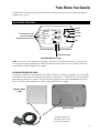
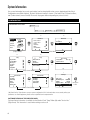
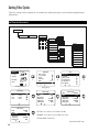
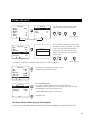
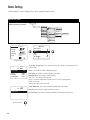
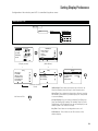
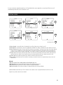
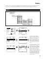
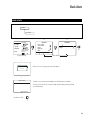
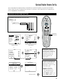
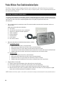
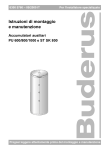
User Manual
1
Table of Contents
This manual assumes that the Poolux Control System has been installed and configured according to the
Installation Manual.
Important Notices . . . . . . . . . . . . . . . . . . . . . . . . . . . . . . . . . . . . . . . . . . . . . . . . . . . . 3
Important Water Safety Instructions . . . . . . . . . . . . . . . . . . . . . . . . . . . . . . . . . . . . . . . . . 4
Important Electrical Safety Instructions . . . . . . . . . . . . . . . . . . . . . . . . . . . . . . . . . . . . . . . 5
Basic Features of the Poolux Control System . . . . . . . . . . . . . . . . . . . . . . . . . . . . . . . . . . . . 6
Poolux Wireless Panel Operation . . . . . . . . . . . . . . . . . . . . . . . . . . . . . . . . . . . . . . . . . . . 7
System Information . . . . . . . . . . . . . . . . . . . . . . . . . . . . . . . . . . . . . . . . . . . . . . . . . . . 8
Setting Day and Time . . . . . . . . . . . . . . . . . . . . . . . . . . . . . . . . . . . . . . . . . . . . . . . . . . 9
Setting Filter Cycles . . . . . . . . . . . . . . . . . . . . . . . . . . . . . . . . . . . . . . . . . . . . . . . . . . .10
Heater Settings . . . . . . . . . . . . . . . . . . . . . . . . . . . . . . . . . . . . . . . . . . . . . . . . . . . . . .12
Setting Display Preferences . . . . . . . . . . . . . . . . . . . . . . . . . . . . . . . . . . . . . . . . . . . . . .13
Renaming Devices . . . . . . . . . . . . . . . . . . . . . . . . . . . . . . . . . . . . . . . . . . . . . . . . . . . .14
Assigning Panel LEDs . . . . . . . . . . . . . . . . . . . . . . . . . . . . . . . . . . . . . . . . . . . . . . . . . .15
Creating Scenes . . . . . . . . . . . . . . . . . . . . . . . . . . . . . . . . . . . . . . . . . . . . . . . . . . . . .16
Vacation Mode . . . . . . . . . . . . . . . . . . . . . . . . . . . . . . . . . . . . . . . . . . . . . . . . . . . . . .18
Chemistry . . . . . . . . . . . . . . . . . . . . . . . . . . . . . . . . . . . . . . . . . . . . . . . . . . . . . . . . .19
Device Timeout. . . . . . . . . . . . . . . . . . . . . . . . . . . . . . . . . . . . . . . . . . . . . . . . . . . . . .20
Check Alerts . . . . . . . . . . . . . . . . . . . . . . . . . . . . . . . . . . . . . . . . . . . . . . . . . . . . . . .21
Spa-Side Panel Set Up . . . . . . . . . . . . . . . . . . . . . . . . . . . . . . . . . . . . . . . . . . . . . . . . .22
Optional Dolphin Remote Set Up. . . . . . . . . . . . . . . . . . . . . . . . . . . . . . . . . . . . . . . . . . . .23
Poolux Wireless Panel Cradle Installation Option . . . . . . . . . . . . . . . . . . . . . . . . . . . . . . . . .24
Faults . . . . . . . . . . . . . . . . . . . . . . . . . . . . . . . . . . . . . . . . . . . . . . . . . . . . . . . . . . .25
Alerts. . . . . . . . . . . . . . . . . . . . . . . . . . . . . . . . . . . . . . . . . . . . . . . . . . . . . . . . . . . .25
2
Important Notices
SAFET Y PRECAUTIONS
FCC STATEMENT
The Warnings, Cautions, and Notes contained in this
manual have the following significance.
WARNING
Maintenance or operating procedures and
techniques that may result in personal injury,
illness, or death if not carefully followed.
CAUTION
Maintenance or operating procedures and techniques
that may result in damage to equipment and/or minor to
moderate personal injury if not carefully followed.
NOTE:
Maintenance or operating procedures and techniques or
information considered important enough to emphasize.
WARNING
During pregnancy, soaking in hot water may
cause damage or injury to the fetus.
Limit spa use to 10 minutes at a time.
This equipment has been tested and complies with the
limits for a Class B digital device, pursuant to Part 15 of
the FCC rules.
These limits are designed to provide reasonable
protection against harmful interference in a
residential installation.
This equipment generates, uses and can radiate radio
frequency energy. Correct installation and proper use
greatly reduce the likelihood of harmful interference to
radio communications, although it does not diminish the
possibility entirely.
If harmful interference is detected when turning the
equipment off and on, the user is encouraged to try to
correct the interference by one or more of the following
measures: (1) Re-orient or relocate the receiving antenna;
(2) Increase the separation between the equipment and
the receiver; or (3) Connect the equipment into an outlet
on a different circuit from the one to which the receiver
is connected.
The user is cautioned that changes and modifications
made to this equipment without the approval of the
manufacturer could void the user’s authority to operate
this equipment.
PREVENT DROWNING
Spa heat speeds up effects of alcohol, drugs or
medicine, and can cause unconsciousness.
Leave spa immediately if uncomfortable or sleepy.
PREVENT CHILD DROWNING
Water attracts children.
Keep unsupervised children away from pool and
spa by installing a safety gate or cover.
SAVE THESE INSTRUCTIONS
3
Important Water Safety Instructions
When installing and using this Control System, basic safety precautions should always be followed, including those
listed below:
READ & FOLLOW ALL INSTRUCTIONS
The effects of hyperthermia include:
Unawareness of impending hazard.
Failure to perceive heat.
Failure to recognize the need to exit the spa.
Physical inability to exit the spa.
Unconsciousness resulting in a danger of drowning.
DANGER - To reduce the risk of drowning from hair
or body entrapment, assure that the suction fittings,
skimmers and main drains in the spa or pool connected to
this Control System are approved for the application.
DANGER - To reduce the risk of injury, do not remove
the suction fittings or main drain covers. Never operate
the spa or pool if these covers are broken or missing.
WARNING - Risk of Accidental Drowning. Extreme
caution must be exercised to prevent unauthorized
access by children. To avoid accidents, ensure that
children cannot use the spa or pool to which this Control
System is connected unless they are closely supervised
at all times.
WARNING - To reduce the risk of injury:
A. The water in a spa to which the Control System is
connected should never exceed 104°F (40°C). Water
temperatures between 100°F (38°C) and 104°F (40°C)
are considered safe for a healthy adult. Lower water
temperatures are recommended for young children
and when spa use exceeds 10 minutes.
B. Since excessive water temperatures have high
potential for causing fetal damage during the early
months of pregnancy, pregnant or possibly pregnant
women should limit spa water temperatures to
100°F (38°C).
C. Before entering a spa, the user should measure the
water temperature with an accurate thermometer
since the tolerance of water temperature-regulating
devices vary.
D. Prolonged immersion in water hotter than 104°F
(40°C) may cause hyperthermia. Hyperthermia occurs
when the internal body temperature reaches a level
several degrees above normal body temperature of
98.6°F (37°C). The symptoms of hyperthermia include
dizziness, fainting, drowsiness, lethargy, and an
increase in the internal temperature of the body.
4
E. The use of alcohol, drugs, or medication can greatly
increase the risk of fatal hyperthermia.
F.
Leave the spa immediately if nausea, dizziness or
headaches occur. Immediately cool the body by taking
a cool shower or by applying cold towels or ice packs.
If the symptoms persist, seek medical attention.
G. The use of alcohol, drugs, or medication before or
during spa use may lead to unconsciousness with the
possibility of drowning.
H. Obese persons and persons with a history of heart
disease, low or high blood pressure, circulatory
system problems, or diabetes should consult a
physician before using a spa.
I.
Persons using medication should consult a physician
before using a spa since some medication may induce
drowsiness or may affect heart rate, blood pressure,
and circulation.
Occasional users of the spa should be made aware
of these important Safety Instructions.
WARNING: People with infectious diseases should
not use a spa or pool.
WARNING: To avoid injury, exercise care when entering
and exiting a spa or pool.
WARNING: Do not use a spa immediately following
strenuous exercise.
CAUTION: Maintain water chemistry to provide safe
bathing environment.
SAVE THESE INSTRUCTIONS
Important Electrical Safety Instructions
When installing and using this Control System, basic safety precautions should always be followed, including those
listed below:
READ & FOLLOW ALL INSTRUCTIONS
1.
DANGER - Risk of electric shock. Before
making any electrical connections, make certain that
the Main Power breaker from the house breaker box
has been turned off.
2.
DANGER - Risk of Electric Shock. Do not
permit any electric appliance, such as a light,
telephone, radio, or television within 5' (1.5m) of a
pool or spa.
3.
WARNING - All electrical work must be
performed by a qualified electrician and must
conform to all national, state, and local codes.
4.
Do not install or service this equipment if
precipitation is present or imminent.
5.
Install the System Control Center in an area that is
not subject to flooding.
6.
Install the System Control Center and all other high
voltage components at least 5' (1.5m) from the inside
wall of the pool or spa. Canadian installations must
be installed at least 3 meters from the inside wall of
the pool or spa.
7.
A terminal marked “GROUND” is provided within
the System Control Center enclosure. To reduce the
risk of electrical shock, connect this terminal to the
grounding terminal of the electric supply panel with
a continuous green insulated copper wire equivalent
in size to the circuit conductors supplying this
equipment, but no smaller than #12 AWG.
8.
9.
A bonding wire connector is provided on the outside
of the System Control Center to accommodate the
connection of a min. #8 AWG solid copper conductor
(#6 AWG in Canada) between this unit and the local
common bonding grid in the spa and pool area.
Additionally, any metal equipment, metal ladders,
metal enclosure of electrical equipment, metal water
pipe, or conduit within 5' of the unit or within 5' of
the pool (3 meters in Canada) must be connected to
the bonding wire connector.
The electrical supply circuit connected to the
System Control Center must be equipped with a
suitably rated disconnect device - a circuit breaker, a
GFCI circuit breaker, switch or other device capable
of opening all ungrounded conductors in the supply
circuit. This disconnect must be installed at least
5' from the pool or spa, but be within sight of and
readily accessible to the user.
10. This Control System provides the temperature
regulation for the pool and spa. The heater that is
connected to the control center must have its own
safety circuit that includes high temperature
limit switch(es).
11.
A suitably rated circuit breaker or a GFCI circuit
breaker, must be installed in the electrical supply
circuit connected to the System Control Center. This
circuit breaker may also provide the disconnect
function referenced in item 9 if it meets the sight
and accessibility criteria.
12. This control system is provided with an Integral
Ground-Fault Circuit Interrupter for the underwater
lighting circuit. It is located on the right side of the
control enclosure under a Weather-Tite cover.
This GFCI must be tested before each use of the pool
or spa. To test the GFCI, follow the following steps:
1. Turn on the underwater pool lighting circuit.
2. Press the ‘RESET’ button fully.
3. Check the underwater lights to be sure they
are illuminated.
4. Press the ‘TEST’ button in order to trip the GFCI.
The ‘RESET’ button will pop out and the
underwater lights will go out.
5. Press the ‘RESET’ again and the underwater lights
will again be illuminated.
If this GFCI fails to operate in this manner, there is
a ground current flowing indicating the possibility
of an electric shock. Disconnect the power until
the fault has been identified and corrected. Do
not use the pool or spa until these problems
have been corrected.
SAVE THESE INSTRUCTIONS
5
Basic Features of the Poolux Control System
Your Poolux Control System is a multi-function pool/spa controller that can manage your complete system. It controls
pumps, valves, lighting, heaters, chlorination, water features - whatever you can throw at it. And it is expandable! You
have the technology in your hands to control your home resort all from one intuitive and intelligent wireless remote.
BASIC FEATURES
• Customize your Panel Display
• Assign LEDs to the functions you prefer
• Turn equipment on and off directly from the Display Screen
• Program your equipment to run automatically when you want it to
• Create a Mood by programming Scenes for relaxing, romance, barbecues, parties, etc.
• Add waterproof control with a Dolphin Floating Remote
• Tell your system to suspend timed functions and events while you are on vacation
6
Poolux Wireless Panel Operation
The Main Menu Screen options shown may be displayed in a different order on your control and will only appear if
available on your system.
BASIC PANEL FUNCTIONS
Mode-Pool
Arrow Left
Arrow Up
Pool Temp
Pool Light
7 LEDs correspond to the 7 items
on the left side of the display.
They light to indicate operation or alert.
Spa Light
Arrow Right
Air Temp
Arrow Down
Filter Pump
Heater
10/09/06 Pool Set 80F
Monday
12:42 PM
Alert/Error
Indicates Fully-Charged Battery
Select
Indicates RF Link Established
Indicates Battery is Charging
The Poolux Wireless Panel
Note: If the wireless panel should freeze (the display is lit, but does not respond to a button press), the panel can
be reset by pressing all four navigation (Left, Right, Up and Down) buttons at the same time. The panel can then be
restarted by pressing and holding the Select button.
CHARGING THE WIRELESS PANEL
The design of the Wireless Panel cradle allows the Wireless Panel to be continuously charged as it rests in the cradle.
If the Wireless Panel should start to discharge, the battery icon will indicate so. The Wireless Panel can be charged by
placing the Panel back into the cradle, or the cord can be disconnected from the cradle and plugged directly into the
back of the Wireless Panel and placed on a table or used handheld while it is charging
Wireless Panel
cradle
Wireless Panel
The power cord can be
placed into either of the
power jack receptacles.
7
System Information
Your system information (accessories and settings) can be viewed within a few screens, beginning with the Check
Configuration menu (Menu 4 below). The basic equipment installed is shown: 1) Pool and/or Spa, 2) Expansion Boxes,
and 3) other features (menus 5 and 6). The menus may appear different depending on your accessories.
CONFIGURATION
CONFIGURATION AT-A-GLANCE
Pool Light
Air Temp
Filter Pump
10/09/06 Pool Set 80F
Monday 12:42 PM
Alert / Error
Heater
Device Control
Scenes / Timer
Heater
Chemistry
Mode
Vacation Mode
Pool
(Main Menu)
3a
3b
Setup
Check Alerts
Setup
Setup
(Display Screen)
Day and Time
Vacation Mode
Filter Cycles
Spa Panel
Dolphin
Panel LEDs
Main Menu
Main Menu
Pool Temp
Spa Light
2b
2a
1
Mode Pool
Setup
Device Timeout
Display
Version Info.
Check Config.
Restore Names
4
Check Config.
Config. Mode
Expansion Boxes
Device Details
Pool + Spa
0
(Setup Screen Menu)
5a
5b
Device Details
Device Details
Pool Light
Spa Light
Filter Pump
Heater
Pool Fill
Chlorine Gen.
Auxiliary 1
Auxiliary 2
Auxiliary 3
Suction Valve
Return Valve
6
Auxiliary 1
Mode
Device Type
Maximum Speed
Output 1
Expansion Boxes
Device No.
Pool + Spa
Triac
H/M/L/Off
Internal
Unassigned
3
(Device Detail Menu)
(3b) Check Config: Right Arrow to see your system configuration. If this information does not accurately reflect your
preferences or current equipment, please contact a qualified service representative.
SOFTWARE VERSION OF THE WIRELESS PANEL
Software Version information is available via the Wireless Panel “Setup” Menu (3b) under “Version Info.”
(Right Arrow). This information is useful when making a service call.
8
Left Arrow
to Exit.
Setting Day and Time
Day of the week and AM/PM settings cannot be set separately. Day of the Week changes automatically according to
the date input, and the AM/PM setting is changed with the hour setting.
SETTING DAY AND TIME
SETTING DAY AND TIME AT-A-GLANCE
Main Menu
Day and Time
Setup
Mode Pool
Pool Temp
Pool Light
Air Temp
Spa Light
Filter Pump
Heater
3
2
1
10/09/06 Pool Set 80F
Monday 12:42 PM
Alert / Error
(Display Screen)
Setup
Main Menu
Device Control
Scenes / Timer
Heater
Chemistry
Mode
Setup
Setup
Pool
Filter CyclesDay and Time
Panel LEDs
Wireless Setup
Rename Devices
Reorder Devices
Day and Time
(Main Menu)
4
Set Time & Date
Set Time
Set mm/dd/yy
Day of the Week
09 50 AM
10/ 09 / 06
Monday
(4) Set Time: When Set Time is highlighted, hour will
automatically blink. Arrow Up or Down to change and Select
to set. Minutes will automatically blink. Arrow Up or Down to
change and Select to set.
Scroll down if the month, date, or year has to be set.
5
Set Time & Date
Set Time
Set mm/dd/yy
Day of the Week
09 50 AM
10 / 19 / 05
Wednesday
(5) Set Month, Date and Year: When Set mm/dd/yy is highlighted, press Select to
change; the month will blink. Arrow Up or Down to change, and Select to set; the date
will blink. Arrow Up or Down to change, and Select to set; the year will blink. Arrow Up
or Down to change and Select to set. The day of the week is set automatically.
Left Arrow to Exit.
9
Setting Filter Cycles
Filter Cycle settings can be configured for use multiple times during a given day, as well as different programming for
different days.
SETTING FILTER CYCLES
SETTING FILTER CYCLES AT-A-GLANCE
Main Menu
Setup
Filter Cycles
Setup
Disable
Filter 1
Filter Timers
Filter 2
Filter 3
Enable
Mode
Pool
Days to Run
Spa
All Days
Timer 1 Start
Filter 4
Weekends
Timer 1 Stop
High
Weekdays
Pump Speed
Low
Sunday
Timer 2
Disable
Monday
Timer 2 Start
Enable
Tuesday
Timer 2 Stop
High
Wednesday
Pump Speed
Low
Thursday
Friday
Saturday
1
2
Pool Temp
Mode Pool
Pool Light
Air Temp
Spa Light
Filter Pump
10/09/06 Pool Set 80F
Monday 12:42 PM
Alert / Error
Heater
(Display Screen)
Main Menu
Device Control
Scenes / Timer
Heater
Chemistry
Mode
Setup
Filter 2
Disabled
Filter 3
Disabled
Filter 4
Disabled
Setup
Pool
6
5
Filter Setup
Disabled
Setup
Filter Cycles
Panel LEDs
Wireless Setup
Rename Devices
Reorder Devices
Day and Time
(Main Menu)
4
Filter 1
3
Filter 1 Setup
Filter 1 Setup
Filter Timers
Mode
Days to Run
Timer 1 Start
Timer 1 Stop
Pump Speed
Enabled
Pool
12:00 AM
12:00 AM
High
Filter
Mode
Days to Run
Timer 1 Start
Timer 1 Stop
Pump Speed
Enabled
Pool
12:00 AM
12:00 AM
High
7
Filter 1 Setup
Filter
Mode
Days to Run
Timer 1 Start
Timer 1 Stop
Pump Speed
Enabled
Pool
12:00 AM
12:00 AM
High
(5) Filter: Press Select to turn Enable or Disable.
(6) Mode: Press Select to choose Mode, Pool or Spa.
(7) Days to Run: Right Arrow.
(Continued on Next Page)
10
Setting Filter Cycles (cont’d)
SETTING FILTER CYCLES
8b
8a
Filter 1 Setup
All Days
Weekends
Weekdays
Sunday
Monday
Tuesday
Filter 1 Setup
Enable
On1
On
On
On
OOn
On
On 1
Wednesday
Thursday
Friday
Saturday
You will be given a choice of weekly or daily
options to set up your filters for operation.
Left Arrow to Exit.
(Filter 1 Setup Menu)
10
9
Filter 1 Setup
Filter
Mode
Days to Run
Timer 1 Start
Timer 1 StopStop
Pump Speed
Enable
Pool
Filter Time 1 Start
Enter Time 12: 00 AM
12:00 AM
12:00 AM
High
The hour will blink. Arrow Up or Down to set the
hour for the first filter cycle to begin. Press Select
to save. The minutes will blink automatically.
Change the minutes in the same way. Press
Select to save and Arrow Left to return to the
previous screen.
Scroll down to “Timer 1 Stop” and repeat the above steps to set a filter cycle stop time.
Left Arrow to Exit.
11
Filter 1 Setup
Filter
Mode
Days to Run
Timer 1 Start
Timer 1 Stop
Pump Speed
Enabled
Pool
Scroll down to Pump Speed. Press Select to choose
the desired pump speed for Filter Cycle 1.
12:00 AM
12:00 AM
High
12
Filter 1 Setup
Timer 2
Timer 2 Start
Timer 2 Stop
Pump Speed
Disable
12:00 AM
12:00 AM
High
For a Second Filter Cycle
Press Select to enable or disable a second run time for Filter Cycle 1.
If enabled, Arrow Down and set Start Time 2 and Stop Time 2 in the same way
described above for Start Time 1 and Stop Time 1.
Program additional filter cycles in the same way.
Left Arrow to Exit.
Two Separate Bodies of Water Using the Same Equipment
If you have two totally separate bodies of water that share the same equipment, configure Filter #2 for Spa.
11
Heater Settings
Actual operation of various heating devices can be configured using this menu.
HEATER SETTINGS
Main Menu
HEATER SETTINGS AT-A-GLANCE
Heater
Set Pool Temp
Set Spa Temp
Enable
Heater
Disable
Enable
Disable
Heat Pump
Heat in Filter
Pool Mode Heat
Spa Mode Heat
Enable
Solar Heat
Disable
Spa Filter Heat
Enable
Polling
Set Polling
Disable
Manaul
Disable
Enable
Disable
2
1
Pool Temp
Mode Pool
Pool Light
Air Temp
Spa Light
Filter Pump
10/09/06 Pool Set 80F
Monday 12:42 PM
Alert / Error
Heater
Main Menu
Device Control eater
Scenes / Timers
Heaterevice Control
Mode
Setup
Vacation Mode
Pool
Of f
(Display Screen)
3
Pool
80˚F
Temp
83˚F
100˚F
Disable
Disable
Disable
Set Pool Temp
Set Spa Temp
Heater
Heat Pump
Pool Mode Heat
4
Pool
Temp
Spa Filter Heat
80˚F
Heater: Press Select to enable or disable the heater.
Heat Pump: Press Select to enable or disable a heat pump.
Pool Mode Heat: Press Select to choose between:
heat in filter - heat during filter cycles only
polling - to measure temperature of water at intervals; heat to set temperature
disable - do not heat
manual - heat upon manual command
(4) Spa Mode Heat: Press Select to enable or disable heat in Spa Mode.
Solar Heat: Press Select to enable or disable solar heat.
Disable
Left Arrow to Exit
12
(3) Set Pool and Spa Temp: Press Select then Arrow Up or Down to set temperature. Press
Select to enter.
Spa Filter Heat: Press Select to enable or disable the heater during spa filter cycles.
Setting Display Preferences
Configuration of the wireless panel LCD is controlled using these menus.
DISPLAY SET UP
DISPLAY SET UP AT-A-GLANCE
Main Menu
Display
Setup
Backlight (min)
Sleep Time (min)
Assign Display2
Key Tone
LCD Contrast
1
2
Pool Temp
Mode Pool
Main Menu
Device Control
Scenes / Timer
Heater
Chemistry
Mode
Setup
Pool Light
Air Temp
Spa Light
Filter Pump
10/09/06 Pool Set 80F
Monday 12:42 PM
Alert / Error
Heater
3
3b
Setup
Setup
Dolphinay and Time
Displaylphin
Version Info.
Restore Names
Check Config.
(Continue Scrolling
Down)
Left Arrow to Exit.
Pool
(Main Menu)
(Display Screen)
Filter CyclesDay and Time
Panel LEDs
Wireless Setup
Rename Devices
Reorder Devices
Day and Time
Setup
4
Display
Backlight (Min)
Sleep Time (Min)
Assign Display2
Key Tone
LCD Contrast
10
10
Pool Temp
Off
(4) Backlight: Press Select then Arrow Up or Down to set
time that wireless panel will stay lit after a button press.
Sleep Time: Press Select then Arrow Up or Down to set time
that wireless panel will stay on before going into sleep mode
to conserve battery.
Assign Display2: You can choose to display Pool Temp, Spa
Temp, pH reading, ORP reading, TDS reading, Filter PSI, Solar
Temperature, or Air Temperature as the second display on the
wireless panel. Press Select to change.
Key Tone: Press Select to turn keypad tone on or off.
LCD Contrast: Press Select to set LCD contrast on the
wireless display.
13
Renaming Devices
Devices can be renamed to personal preference. For instance, Aux Device 1 can easily be renamed “Waterfall” and will
then be shown that way on the control. Names are stored in the main control system.
RENAMING DEVICES
RENAMING DEVICES AT-A-GLANCE
Main Menu
Setup
Rename Devices
Pool Light
Air Temp
Filter Pump
10/09/06 Pool Set 80F
Monday 12:42 PM
Alert / Error
Heater
3
Setup
Main Menu
Pool Temp
Spa Light
Keyboard Screen
2
1
Mode Pool
(Choose Device)
Device Control
Scenes / Timers
Heater
ModeModeodessfgsfs
Setupode
Vacation Mode
Pool
Po
Off
(Display Screen)
Rename Devices
In Rename Device, scroll to the
available device and Arrow Right.
5
ABC
A
B
C
D
E
F
Exit
G
H
I
J
K
L
Save
M
N
O
P
Q
R Clear
S
T
U
V
W
X
Back
Y
Z
1
2
3
4
Shift
5
6
7
8
9
0 Space
Left Arrow to Exit.
14
Reorder Devices
Day andTime
Right Arrow to Rename Device.
4
Filter Pump
Pool Light
Spa Light
Heater
Aux Device 1
Filter Cycles
Panel LEDs
Wireless Setup
Rename Devices
Arrow to the chosen letter, then press
Select. Continue until the completed new
name for the Device is in the top window.
Arrow to “Save,” then press Select.
Display will revert to Device Control
screen with new name displayed.
Assigning Panel LEDs
The LEDs to the left of the display can be reassigned to devices that are considered most important for that particular
control panel. This is helpful for monitoring the on/off state of these devices without reading the display.
ASSIGNING PANEL LEDs
ASSIGNING PANEL LEDs AT-A-GLANCE
Main Menu
Setup
Panel LEDs
LED 1
thru 7
Device List
Scene List
Mode
Chemistry
Unassigned
1
2
Pool Temp
Mode Pool
Pool Light
Air Temp
Spa Light
Filter Pump
10/09/06 Pool Set 80F
Monday 12:42 PM
Alert / Error
Heater
3
Main Menu
Device Control
Scenes / Timers
Heater
ModeModeodessfgsfs
Setupode
Vacation Mode
Setup
Pool
P
Off
Filter Cycles
Panel LEDs
Wireless Setup
Rename Devices
Reorder Devices
Day and Time
(Display Screen)
4
Panel LEDs
LED 1Pool LightMode
LED 2
Pool Light
LED 3
Spa Light
LED 4
Filter Pump
LED 5
Heater
LED 6
Cleaner
5
LED Assignment
Device List
Scene List
Mode
Unassigned
You may choose, for example, equipment that you would like to associate with
“LED 1” (Menu 4), and its related assigned functions. In this case, Arrow Right
highlights the “LED Assignment” list (Menu 5).
6
LED Assignment
Filter Pump
Pool Light
Spa Light
Heater
Aux Device 1
Left Arrow to Exit
From the Device List, Right Arrow to the specific device listed in Menu 6. Arrow
Down to the equipment you wish to assign. Press Select.
Note: When a piece of equipment is assigned to a panel LED light, from the Display Screen you can turn that
equipment on and off or scroll through the options simply by highlighting that item, using the Up/Down arrow keys,
and pressing Select.
15
Creating Scenes
Scenes are used to assign one or more devices to a preset timer. For example, a scene named “Evening” could be
created that turns on a pool or spa light, and an auxiliary device such as a waterfall at the same time each evening.
CREATING SCENES
CREATING SCENES AT-A-GLANCE
Off
On
Main Menu
Scenes / Timers
Scene 1
Select Devices
Scene 2 -20
Scene Timeout
Timers
Timer 1 Start
All Days
Timer 1 Stop
Weekends
Days to Run
Weekdays
Timer 2 Start
Sunday
Timer 2 Stop
Monday
Days to Run
Pool Temp
Pool Light
Air Temp
Spa Light
Filter Pump
10/09/06 Pool Set 80F
Monday 12:42 PM
Alert / Error
Heater
(Display Screen)
Rename Scene
Thursday
Run in Vacation
Yes
Friday
Clear Scene
No
Saturday
Main Menu
Scene Control
Mode
Heater
Chemistry
Device Control
Scenes / Timers
Wireless Setup
Pool
(Main Menu)
5
Scene 1
16
Wednesday
No
3
4
Select Devices
Scene Timout
Timers
Timer 1 Start
Timer 1 Stop
Days To Run
Yes
2
1
Mode Pool
Scene 1
12
Disable
12:00 AM
12:00 AM
Tuesday
Allow Heat
Select Devices
Scene Timout
Timers
Timer 1 Start
Timer 1 Stop
Days To Run
12
Disable
12:00 AM
12:00 AM
Scene 1
Scene 2
Scene 3
Scene 4
Scene 5
Scene 6
On
Unused
Unused
Unused
Unused
Unused
A scene can also be manually turned on or off. If multiple devices are assigned to a scene, they will turn on or off
simultaneously when the scene is turned on or off.
CREATING SCENES
6
7
Scene 1
Scene 1
Select Devices
Scene Timout
Timers
Timer 1 Start
Timer 1 Stop
Days To Run
12
Disable
12:00 AM
12:00 AM
Select Devices
Scene Timout
Timers
Timer 1 Start
Timer 1 Stop
Days To Run
9
Scene 1
12
Disable
12:00 AM
12:00 AM
Select Devices
Scene Timout
Timers
Timer 1 Start
Timer 1 Stop
Days To Run
10
Scene 1
Select Devices
Scene Timout
Timers
Timer 1 Start
Timer 1 Stop
Days To Run
8
12
Disable
12:00 AM
12:00 AM
12:00 AM
11
Scene 1
Scene 1
Timer 2 Start
Timer 2 Stop
Days To Run
Allow Heat
Rename Scene
Run In Vacation
12
Disable
12:00 AM
12:00 AM
12:00 AM
Clear Scene
No
No
Left Arrow to Exit
(3) Scene Control: Scene will show as Unused until set up. Press Select to turn Scene On or Off.
(4) Select Devices: Right Arrow to show list of equipment available. Press Select to link device to scene (menu not shown).
(5) Scene Timeout: Press Select. The hours will flash, waiting for your changes. Then Arrow Up or Down to set Scene timeout
in hours (1 to 12). The default is 12 hours. Press Select to set. (Note: The Timeout is the length of time a Scene will run if
turned on manually and not turned off.) (6) Timers: Press Select to Enable or Disable Scene running at designated times.
(7) Timer 1 Start: Press Select, then Arrow Up or Down to set time for Scene to begin. As the hour flashes, press the Arrow
Up/Down key. Press Select. As the minute flashes, press the Arrow Up/Down key. Press Select. Arrow Left to Exit.
(8) Timer 1 Stop: Press Select, then Arrow Up or Down to set time for the Scene to end.
(9) Days to Run: Right Arrow, then Press Select for each day you want the Scene to run automatically at the set time. Left
Arrow to Exit.
Menu 10:
(10a) Timer 2 Start, Timer 2 Stop, and Days to Run. Repeat steps 7-9.
(10b) Allow Heat: Press Select to designate whether heat should run during Scene.
(10c) Rename Scene: Right Arrow to name or rename the programmed Scene.
(10d) Run in Vacation: Press Select to Enable or Disable the Scene while in Vacation Mode.
(11) Clear Scene: (Scroll down past “Run In Vacation”) Press Select to clear a programmed Scene. Confirm Yes or No.
Repeat for any other Scenes that are created.
17
Vacation Mode
Vacation Mode is used to disable scene timers when going on vacation. Each scene has an option in its setup called
“Run in Vacation.” If set to Yes, the scene timers will continue to operate even though Vacation Mode is turned on or off.
VACATION MODE
VACATION MODE AT-A-GLANCE
Main Menu
Vacation Mode
1
Mode Pool
Pool Temp
Pool Light
Spa Light
Filter Pump
Heater
Air Temp
10/09/06 Pool Set 80F
Monday 12:42 PM
Alert / Error
(Display Screen)
18
2
Main Menu
Device Control
Scenes / Timer
Heater
Chemistry
Mode
Vacation Mode
Setup
Pool
On
Vacation Mode will appear within
the Main Menu. (Depending on
your installed accessories, Vacation
Mode may not appear on the first
Main Menu Screen. In that case,
Scroll Down.)
Once Vacation Mode is Highlighted,
Select to turn On or Off.
Chemistry
High and Low Limits for each chemistry reading has been set by the manufacturer. If the chemistry sensor reading is outside the
present limits, an alert will flash on the Main Menu Screen. Default limits can be changed to your preference.
CHEMISTRY
CHEMISTRY SETTINGS AT-A-GLANCE
Main Menu
Chemistry
Set High ORP
Set Low ORP
Set High pH
Enable
Set Low pH
Set High TDS
Ecomatic
Disable
Set Low TDS
ORP threshold
Enable
Chlorine Gen.
Extend Filter Cycle
Disable
Chemical Feeder
Chemical Feeder
Enable
Duration in min
Disable
1
2
Pool Temp
Mode Pool
Main Menu
Pool Light
Air Temp
Spa Light
Filter Pump
10/09/06 Pool Set 80F
Monday 12:42 PM
Alert / Error
Heater
Mode
Heater
Chemistry
Device Control
Scenes / Timers
Wireless Setup
(Display Screen)
(Main Menu)
3
pH
7.5
ORP mV
710
Set High ORP
Set LOW ORP
Set High pH
Set Low pH
Set High TDS
4
TDS ppm
pH
2400
7.5
800
650
7.9
7.2
4000
TDS ppm
ORP mV
2400
710
Set Low TDS
Chlorine Gen.
5
2000
6
pH
ORP mV
TDS ppm
7.5
710
2400
Set Low TDS
Chlorine Gen.
Pool
2000
Ecomatic Setup
Chlorine Gen.
Set ORP Level
Extend filter
POC Control
Enable
700
Disable
Off
(3-4) Chemistry High and Low
Limits: High and Low Limit defaults
have been set by manufacturer.
However, if you prefer different limits,
you may change them by pressing
Select (as shown), then Arrow Up or
Down to change. Press Select again
to save.
(5-6) Chlorine Generator: If you have
an optional ECOmatic attached to
your system, Right Arrow on Chlorine
Gen. (shown) to access the ECOmatic
Setup. Press Select to Enable or
Disable the Chlorine Gen., Extend
Filter, or POC Control (if available). The
ORP level is changed by highlighting
Set ORP Level. Select. When flashing,
change the ORP level value with the
UP or Down key. Press Select to set.
Left Arrow to Exit.
19
Device Timeout
A Device Timeout is the length of time a device will run if turned on manually and not turned off.
DEVICE TIMEOUT
DEVICE TIMEOUT AT-A-GLANCE
Main Menu
Setup
1
Mode Pool
Pool Light
Air Temp
Filter Pump
10/09/06 Pool Set 80F
Monday 12:42 PM
Alert / Error
Heater
Pool Fill 30 min
2
Pool Temp
Spa Light
Device Timeout
3
Main Menu
Device Control
Scenes / Timer
Heater
Chemistry
Mode
Setup
Setup
Pool
Setup
Filter Cycles
Panel LEDs
Device Timeout
Rename Devices
Dolphin
Day and Time
(Display Screen)
4
Device Timeout
Pool Fill
30 min
(4) Device Timeout: Timeout options will appear in the Device Timeout list. Press Select, then Arrow Up or Down to change
the length of time to run, or Off. Select to save.
Left Arrow to Exit.
20
Check Alerts
CHECK ALERTS
CHECK ALERTS AT-A-GLANCE
Main Menu
Check Alerts
1
Pool Temp
Mode Pool
Pool Light
Air Temp
Spa Light
Filter Pump
Heater
10/09/06 Pool Set 80F
Monday 12:42 PM
Alert / Error
(Display Screen)
2a
2b
Main Menu
Main Menu
Device Control
Scenes / Timer
Heater
Chemistry
Mode
Setup
Check Alerts
Setup
Setup
Pool
(Main Menu)
3
!
Alerts & Errors
If there is no error, this pop-up screen will appear.
No ALERTS
4
Alerts & Errors
Check Air Sensor
If there is an error, the recommended action will appear on the display.
In this case, the Air Sensor connector needs attention (became disconnected
or malfunctioned).
Check Air Sensor
Left Arrow to Exit.
21
Spa-Side Panel Set Up
You may choose the equipment that you would like to associate with the first two Spa Panel buttons. The Temp and
Mode buttons cannot be reassigned. Choose the piece of equipment from the Device List, then press Select when the
piece of equipment you desire is highlighted as illustrated below.
ASSIGNING SPA PANEL BUTTONS
ASSIGNING SPA PANEL BUTTONS AT-A-GLANCE
Main Menu
Light
Setup
Spa Panel
Aux
Temp
Pool
Spa
Spa Panel Btn 1
Spa Panel Btn 2
Spa Panel Btn 3
Spa Panel Btn 4
First two buttons can be assigned to
the equipment of your choice.
Pool Temp
Mode Pool
Pool Light
Air Temp
Spa Light
Filter Pump
10/09/06 Pool Set 80F
Monday 12:42 PM
Alert / Error
Heater
3
2
1
Main Menu
Device Control
Scenes / Timers
Heater
ModeModeodessfgsfs
Setupode
Vacation Mode
Pool
Off
P
Setup
Spa Panel
Dolphincation Mode
Displayclesnel
Version Info.ersion Info.olphin
Restore Names
Check Config.
Scroll down in the Setup Menu to Spa Panel
(Display Screen)
5
4
Spa Setup
Spa Panel Btn 1
Pool Light
Spa Panel Btn 2
Spa Light
Spa Panel Btn 3
Temp
Spa Panel Btn 4
Mode
Spa Buttons
Device List
Scene List
Unassigned
6
Spa Buttons
Heater
Spa Light
Filter Pump
Pool Light
Aux Device 1
Left Arrow to Exit.
In this case (Menu 6), Heater is highlighted. Press Select to assign the Heater for the “Spa Panel Btn 1” as requested in
Menu 4. In this example, Select returns you to Menu 4, and confirms reassignment of Spa Panel Btn 1 to Heater.
22
Optional Dolphin Remote Set Up
You must designate the equipment that you would like the Jet and the Aux buttons to operate from the Dolphin
Remote. Choose the piece of equipment from the Device List, then press Select when the piece of equipment you
desire is highlighted as illustrated below.
ASSIGNING DOLPHIN REMOTE BUTTONS
ASSIGNING DOLPHIN REMOTE BUTTONS AT-A-GLANCE
Main Menu
Dolphin
Setup
Dolphin Jet
Dolphin Aux 1
Dolphin Aux 2
Dolphin Aux 3
Dolphin Address
2
1
Pool Temp
Mode Pool
Main Menu
Device Control
Scenes / Timer
Heater
Chemistry
Mode
Setup
Pool Light
Air Temp
Spa Light
Filter Pump
10/09/06 Pool Set 80F
Monday 12:42 PM
Alert / Error
Heater
Jets Button
Aux Buttons
(Display Screen)
Setup
Pool
(Main Menu)
3a
3b
Setup
Setup
Filter CyclesDay and Time
Panel LEDs
Insteon Devices
Wireless Setup
Day and Time
Spa Panel
Dolphin
Display
Device Timeout
Version Info.
Rename Devices
Reorder Devices Dolphin Address (Menu 4):
See Dolphin Remote Operation
Manual regarding Pool Addressing.
Verify that the code set in the
Dolphin Remote matches the
number designated on the
Wireless Panel.
(Setup Menu)
4
5
Dolphin Setup
Dolphin Buttons
Dolphin Jet
Unassigned
Dolphin Aux 1
Unassigned
Dolphin Aux 2
Unassigned
Dolphin Aux 3
Unassigned
Dolphin Address
Assigned
Device List
Scene List
Unassigned
1
Left Arrow to Exit.
The Dolphin has predefined buttons
for Lights 1 & 2, Filter Pump, and
Heater. Arrow Right within the
Dolphin Buttons “Device List” menu
on the wireless panel.
The Device List will allow:
1) Cleaner Pump Activation.
The system determines the
proper cleaner to activate,
2) an Aux Device, numbers 1 - 41,
3) an Aux Valve, numbers 1 - 14.
23
Poolux Wireless Panel Cradle Installation Option
The Wireless Panel comes with a charging cradle that can be installed on a wall inside the home for a convenient
display while charging. Installing the cradle is not necessary to charge the panel; it can be charged independently from
the cradle with the charge cord.
INSTALLING THE WIRELESS PANEL CRADLE
The cradle must be mounted in a location where it receives a strong signal at all times. Check to see that the panel receives
a strong signal in the location you are considering prior to installation by holding the panel against the wall and checking the
signal there. This will ensure that if a noteworthy problem occurs at the pool, the panel will be able to alert
the homeowner.
1.
Find a suitable location for mounting the cradle. The location should be convenient for the homeowner and near an
electrical outlet.
Avoid mounting the cradle near the following:
A. heat sources
B. areas of excessive moisture (such as a bathroom)
C. television sets and other electronic equipment
D. cordless telephones
E. personal computers
F. microwave ovens
G. electric motors
H. other wireless devices
2.
Mount the cradle with the included mounting hardware as follows:
A. For sheetrock or plaster:
1.
2.
3.
4.
5.
Hold the cradle on the wall in its desired location.
With a pencil, mark a dot on the wall in the center of each mounting hole.
Drill two 3/16” holes (1/2” to 3/4” deep) in the wall where the dots are located.
Insert the plastic anchors into the two holes. Tap the anchors with a hammer until only the round head shows.
Hold the cradle over the anchors and secure by screwing the two screws into the anchors.
B. For wood surfaces:
1.
2.
3.
4.
3.
Hold the wall bracket on the wall in its desired location.
With a pencil, mark a dot on the wall in the center of each mounting hole.
Drill two 3/32” holes (1/2” to 3/4” deep) in the wall where the dots are located.
Hold the cradle over the drilled holes and secure by screwing the two screws into the holes.
Using the Wireless Panel Cradle
A. Plug the charge cord into the bottom of the cradle and into an electrical outlet.
B. Set the wireless panel in the cradle. It will snap into place, and is held magnetically.
C. Press the Select button on the wireless panel to wake up the wireless panel if the display is blank.
D. When the wireless panel is not in use, placing it on the cradle will ensure that it stays fully charged, has a good
signal, and can alert the homeowner to any problems in the pool.
NOTE: Whenever the wireless panel is on the cradle or connected to the charge cord, the display will not sleep and will remain on.
24
Faults
A Fault is an indication of a serious error that can affect the operation of the pool system. One of the following
messages will blink on the lower right side of the Wireless Pool Control display when a fault occurs.
FAULT MESSAGES AND MEANINGS
AIR SENSOR FAULT
The Air Temperature Sensor has failed or has been disconnected.
WATER SENSOR FAULT
The Water Temperature Sensor has failed or has been disconnected.
SOLAR SENSOR FAULT
The rooftop temperature sensor has failed or has been disconnected.
pH SENSOR FAULT
The pH Sensor has failed or has been disconnected.
ORP SENSOR FAULT
The ORP Sensor has failed or has been disconnected.
TDS SENSOR FAULT
The Conductivity Sensor has failed or has been disconnected.
POC FAULT
The Pool Controller has lost communication with the POC board.
Alerts
An Alert will appear on the display during a change in System status, or when System levels are out of user-specified
limits. One of the following messages will blink on the lower right side of the Wireless Poolux display when the System
is bringing an Alert to your attention.
ALERT MESSAGES AND MEANINGS
AIR SENSOR FREEZE
The air temperature has reached the preselected 34°F - 40°F set by the user.
The Filter Pump & devices configured to be freeze protected will turn on.
WATER SENSOR FREEZE
The water temperature has reached the preselected 34°F - 40°F set by the user.
The Filter Pump & devices configured to be freeze protected will turn on.
CHEMICAL FEEDER PURGE
The Chemical Feeder is purging (15 seconds). The Filter Pump will not shut off
while this is occurring.
SOLAR PANEL DRAINING
The Solar Valve is being held open to allow the solar panels to drain. The Filter Pump
will be held off while this occurs.
pH LOW
The pH of the water is below the user-specified low limit.
pH HIGH
The pH of the water is above the user-specified high limit.
ORP LOW
The ORP of the water is below the user-specified low limit.
ORP HIGH
The ORP of the water is above the user-specified high limit.
TDS LOW
The TDS of the water is below the user-specified low limit.
TDS HIGH
The TDS of the water is above the user-specified high limit.
DIRTY FILTER
The water pressure is above the dirty filter detection threshold.
25
NOTES
26
NOTES
27
balboa instruments, inc.
1382 bell avenue
tustin, ca 92780
www.balboa-instruments.com
28
t 714-384-0384
f 714-384-0338
pn: 40628_A
February 12, 2007