1
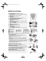
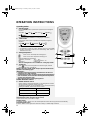
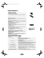
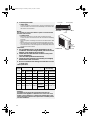
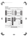
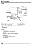
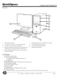
33933049GB.fm Page 4 Monday, January 10, 2005 5:27 PM INSTRUCTIONS FOR USE SLIM RANGE SINGLE SPLIT AIR CONDITIONER WITH ECOLOGICAL GAS AND WITH GAS R22 PREPARATION BEFORE USE SAFETY PRECAUTIONS IDENTIFICATION OF PARTS REMOTE CONTROL OPERATION INSTRUCTIONS MAINTENANCE TROUBLESHOOTING PROTECTION INSTALLATION INSTRUCTIONS SLIM RANGE R22 SLIM RANGE This appliance is marked according to the European directive 2002/96/EC on Waste Electrical and Electronic Equipment (WEEE). This guideline is the frame of a European-wide validity of return and recycling on Waste Electrical and Electronic Equipment. 4 33933049GB.fm Page 5 Monday, January 10, 2005 5:27 PM PREPARATION BEFORE USE Before using the air conditioner, be sure to check and preset the following. Remote Control presetting The remote control is NOT preset as Cooling Only Air Conditioner or Heat Pump by manufacturer. Each time the remote control batteries are replaced, the Cooling indicator and Heating indicator will flash alternately on the remote control LCD. The user can preset the remote control depending on the air conditioner type purchased as follows: Pressing any button when flashes, Heat Pump is set. Pressing any button when flashes, Cooling Only is set. If you don’t press any button within 12 seconds, the remote control is preset as Heat Pump automatically. Note: If the air conditioner you purchased is a Cooling Only one, but you preset the remote control as Heat Pump, it doesn’t matter. But if the air conditioner you purchased is a Heat Pump one, and you preset the remote control as Cooling Only, then you CANNOT preset the Heating operation with the remote control. Back-light function (optional) Pressing any button of the remote control for about 2 seconds, the back-light turns on. Once the button is released, it automatically turns off after 10 seconds. Note: Back-light is an optional function. Auto Restart Presetting The Auto restart function is not preset by the manufacturer. To set the auto restart function, press the Emergency button (ON/OFF) on the indoor unit for at least 5 seconds. A buzz sound will signal that the auto restart function is set and the air conditioner is in standby. To cancel the auto restart function, press the Emergency button (ON/OFF) on the indoor unit for at least 5 seconds. A buzz sound will signal that the auto restart function is cancelled and the air conditioner is in standby. SAFETY PRECAUTIONS Be sure not to do the following. It is harmful to your health if the cool air reaches you for a long time. It is advisable to let the air flow be deflected to all the room. Prevent the air flow from reaching the gas burners and stove. Do not touch the operation buttons when your hands are wet. Pay attention to such a situation. Do not repair the appliance by yourself. If this is done incorrectly, it may cause an electric shock, etc. Be sure to follow this instruction. Do not put any objects on the outdoor unit. Earthing is essential. It is the user’s responsibility to have the appliance be earthed according to local laws by a qualified technician. Warning: Incorrect handling could cause a serious hazard, such as death, serious injury, etc. Use correct power supply in accordance with the rating plate requirement. Don't use any extension cord for power supply. Otherwise, serious faults or hazard may occur or a fire may break out. Keep the power supply circuit breaker or plug from dirt. Connect the power supply cord to it firmly and correctly, lest an electric shock or a fire break out due to insufficient contact. Do not use the power supply circuit breaker or pull off the plug to turn it off during operation. This may cause a fire due to spark, etc. Do not twist, pull or press the power supply cord, lest the power supply cord be broken. An electric shock or fire is probably caused by a broken power supply cord. Never insert a stick or similar obstacle in the unit. Since the fan rotates at high speed, this may cause an injury. Turn off the appliance with remote control first before cutting off power supply if malfunction occurs. 5 33933049GB.fm Page 6 Monday, January 10, 2005 5:27 PM IDENTIFICATION OF PARTS A B Indoor unit R C I MG H E F D L N Outdoor unit O P Q Indoor unit A - Air Intake B - Front Panel C - Operation Panel D - Display E - Air Outlet F - Vertical Adjustment Louver G - Horizontal Adjustment Louver H - Charcoal Filter (optional) I - Electrostatic Filter (optional) L - Remote Control M - Air Filter Outdoor unit N - Air Intake O - Pipes and Power Connection Cord P - Drain Hose Note: Condensate water drains at COOLING or DRY operation. Q - Air Outlet R - Rating plate (product tecnical data) NOTE: The figure above is only a simple presentation of the unit, it may not match the external appearance of the unit you purchased. 6 33933049GB.fm Page 7 Monday, January 10, 2005 5:27 PM Operating and Display 1 For SLIM model without LED only 2 3 4 5 1. Compressor indicator It lights up when compressor is running. 2. Timer Indicator It lights up during the set time. 3. Run Indicator It is on during operation. It flashes during defrosting. 4. Signal Receptor Receives signal from the remote control. 5. Emergency button Used to control the unit when the remote control is out of work. Used to set or cancel auto restart function. (See page 5) Note: The shape and position of the switches and indicators may vary from different models, but their function are similar. 7 33933049GB.fm Page 8 Monday, January 10, 2005 5:27 PM Operating and Display SILM model without LED SLIM model with LED 1. Compressor indicator (Red) It lights up when compressor is running. 2. Signal receptor Receive signal from the remote control. 3. Sleep indicator (Yellow) It lights up when unit is in sleep mode. 4. Timer Indicator (Orange) It lights up during the set time. 5. LED display Display set temperature when temperature is being set. Display room temperature in other time. 6. Run Indicator (Green) It is on during operation. 8 33933049GB.fm Page 9 Monday, January 10, 2005 5:27 PM REMOTE CONTROL The remote control transmits signals to the system. A. ON/OFF button B. C. D. E. F. G. H. I. The appliance will be started when it is energized or will be stopped when it is in operation, if you press this button. MODE button Used to select the operation mode. FAN button Used to select fan speed in sequence auto, high, medium or low. ROOM TEMPERATURE SETTING buttons Used to select the room temperature. Used to set time in TIMER mode. SWING button Used to stop or start vertical adjustment louver swinging and set the desired up/down airflow direction. 6th Sense button Used to enter fuzzy logic operation directly, regardless of the unit is on or off. TIMER SET/CANCEL button Used to set or cancel the timer operation. SLEEP button Used to set or cancel Sleep Mode operation. JET button Used to start or stop the fast cooling. (Fast cooling operates at high fan speed with 18°C set temp automatically). Indication symbols on LCD: Jet indicator 6th Sense indicator Sleep indicator Signal transmit Cooling indicator Dry indicator Fan only indicator *Heating indicator I D E F C G H A B Auto fan speed High Used to regulate High fan speed temperature in 6th Medium fan speed Sense mode or Dry Low fan speed mode (See page 11 Display set temperature “6th Sense mode” for Low Display set timer details) NOTE: The remote control display continues indicating even when the unit has run down. How to insert the batteries Remove the battery cover in the direction of the arrow. Insert new batteries making sure that the (+) and (-) of battery are matched correctly. Refit the cover by sliding it back into position. NOTE: Use 2 LR03 AAA (1.5 V) batteries. Do not use rechargeable batteries. Replace batteries with new ones of the same type when the display becomes dim. If the replacement is done within 1 minute, the remote control will keep original presetting. However, if you want to change the presetting from Heat Pump to Cool Only or Cool Only to Heat Pump, you should reload batteries 3 minutes after removing the old ones. (Please refer to page 5 for details.) Storage and tips for using the remote control The remote control can be stored in a holder mounted on the wall. NOTE: The remote control holder is an optional part. How to use the remote control To operate the room air conditioner, point the remote control at the signal receiver. The remote control will operate the air conditioner at a distance of up to 7 m when pointing at the signal receiver of the indoor unit. Choose cooling only remote control or heat pump. Please refer to page 5 “Preparation before use“ for details. Back-light function (optional) Please refer to page 5 “Preparation before use“ for details. Remote control holder Signal receiver 9 33933049GB.fm Page 10 Monday, January 10, 2005 5:27 PM OPERATION INSTRUCTIONS Operating modes 1. Selecting mode Each time MODE button is pressed, the operation mode is changed in sequence: COOLING DRY FAN ONLY HEATING IMPORTANT: Heating mode is NOT available for cooling only air conditioner. 2. “FAN” mode Each time the “FAN” button is pressed, the fan speed is changed in sequence: AUTO HIGH MEDIUM LOW IMPORTANT: In “FAN ONLY” mode, only “High”, ”Medium” and “Low” are available. In “DRY” mode, airflow is set at “Low” automatically, “FAN” button is ineffective in this case. 3. Setting temperature 5 Press once to raise temperature setting by 1°C Press once to lower temperature setting by 1°C Range of available set temperature: *HEATING, COOLING 18°C ~ 32°C DRY room temperature ± 2°C FAN ONLY unable to set *NOTE: Heating mode is NOT available for cooling only models. 2 4. Turning on Press button, when the appliance receives the signal, the RUN indicator of the indoor unit lights up. SWING, 6th Sense, TIMER, SLEEP and JET operation modes will be specified in the following pages. IMPORTANT: Changing modes during operation, sometimes the unit does not response at once. Wait 3 minutes. During heating operation, air flow is not discharged at the beginning. After 2-5 minutes, the air flow will be discharged until temperature of indoor heat exchanger rises. Wait 3 minutes before restarting the appliance. Airflow direction control 5. Airflow direction control Vertical airflow is automatically adjusted to a certain angle in accordance with the operation mode after turning on the unit. The direction of airflow can also be adjusted to your own requirement by pressing the “SWING” button of the remote control. operation mode direction of airflow COOLING, DRY horizontal *HEATING, FAN ONLY downward *Heating mode is only available for heat pump models. Vertical airflow control (using the remote control) Use the remote control to set the flow angles. Swinging airflow. Pressing the “SWING” button once, the vertical adjustment louver will swing up and down automatically. Desired airflow direction. Press the “SWING” button again when the louvers swing to a suitable angle as desired. 10 1 3 4 33933049GB.fm Page 11 Monday, January 10, 2005 5:27 PM ù Horizontal airflow control (with hands) Turn the control rods of the horizontal adjustment louvers to change horizontal air flow as shown. Note: The shape of the unit may look different from that of the air conditioner you have selected. Control rods of horizontal adjustment louver Important: Do not turn the vertical adjustment louvers manually, otherwise malfunction may occur. If that happens, first turn off the unit and cut off the power supply, then restore the power supply again. It is better not to let the vertical adjustment louver tilt downward for a long time at COOLING or DRY mode to prevent condensed water from dripping. 6th Sense mode Pressing the 6th Sense button, the unit enters fuzzy logic operation directly regardless whether the unit is on or off. In this mode, temperature and fan speed are automatically set according to the actual room temperature. Operation mode and temperature are determined by indoor temperature Heat pump models Indoor temperature Operation mode 21°C or below HEATING 22°C 21°C - 26°C DRY Room temperature decreases 1.5°C after operating for 3 minutes Over 26 COOLING 26°C Indoor temperature Operation mode Target temperature 26°C or below DRY Room temperature decreases 1.5°C after operating for 3 minutes Target temperature Cooling only models Over 26 COOLING 26°C Important: 6th Sense button is ineffective in JET mode. Note: Temperature, airflow and direction are controlled automatically in 6th Sense mode. However, a decrease or rise of up to 2°C can be set with the remote control if you still feel uncomfortable. A decrease or increase up to 2°C can be set in 6th Sense mode Your feeling Slightly warmer A decrease up to 2°C can be set Slightly cooler Button Adjustment procedure Press once to lower the set temp by 1°C Press twice to lower the set temp by 2°C Press once to raise the set temp by 1°C A rise up to 2°C can be set Press twice to raise the set temp by 2°C Uncomfortable because of unsuitable air flow volume. Indoor fan speed alternates among High, Medium and Low each time this button is pressed. Uncomfortable because of unsuitable flow direction. Press it once, the vertical adjustment louver swings to change vertical airflow direction. Press it again, swings stops. For horizontal airflow direction, please refer to the previous page for details. 11 33933049GB.fm Page 12 Monday, January 10, 2005 5:27 PM Timer mode It is convenient to set the timer on with TIMER button when you go out in the morning to achieve a comfortable room temperature at the time you get home. You can also set timer off at night to enjoy a good sleep. Timer setting Set a switch-on timer when the appliance is off. Set a switch-off timer during operation. As time goes by, the LCD on the remote control only displays the remaining time, not the set temperature. The previous set time is stored and the next set time begins with the previous setting. On- timer and off-timer can not be set at the same time. The room may not reach your desired temperature within the preset time; this depends on the size of the room. 1. E.g. setting the next operation after 9.5 hours Set the desired operating mode, temperature and indoor fan speed, then press the TIMER button (1); “h” will flash on the LCD. 2. E.g. setting the next operation after 9.5 hours Point the remote control at the signal receiver of the indoor unit, and press the or button (2) when “h” flashes. Choose the time you desire, then press the TIMER button. A “beep” can be heard: Timer indicator on the indoor unit lights up. “h” stops flashing. Important: Press the TIMER button, “h” flashes on the LCD, then you can set the time. Each time the or button is pressed: If the desired time is within 10 hours, the set time increases or decreases by 0.5 hour. If the desired time is beyond 10 hours, the set time increases or decreases by 1 hour. The time that can be set ranges between 0.5 and 24 hours. 3. E.g. cancelling the switch-on time after 9.5 hours To cancel the set time: press the TIMER button again, a “beep” can be heard and the timer indicator on the indoor unit lights off. JET mode JET mode is used to start or stop fast cooling. Fast cooling operates at high fan speed, changing the set temperature automatically to 18°C. JET mode can be set when the appliance is in operation or energized. In JET mode, you can set airflow direction and timer. If you want to quit from JET mode, press any-JET, MODE, FAN, ON/OFF or TEMPERATURE SETTING button, the display will return to the original mode. Note: SLEEP and 6th Sense buttons are not available in JET mode. 12 2 2 1 33933049GB.fm Page 13 Monday, January 10, 2005 5:27 PM Sleep mode SLEEP mode can be set in COOLING or HEATING operation mode. This function gives you a more comfortable environment for sleep. In SLEEP mode, The appliance will stop operation automatically after operating for 8 hours. Fan speed is automatically set at low speed. *The set temperature will rise by max. 1°C if the appliance operates in cooling mode for two hours, then it will remain constant. The set temperature will decrease by max 3°C is the appliance operates in heating mode for 3 hours, then it will remain constant. COOLING 8 hours timer 1 hour 1 hour 1 Rise by 0.5°C STOP SET TEMP. Rise by 0.5°C START **HEATING 8 hours timer 1 hour SET TEMP. 1 hour 1 hour Decrease by 1°C Decrease by START Decrease by STOP *: In cooling mode, if room temperature is 26°C or above, set temperature will not change. **: Heating is NOT available for cooling only air conditioner. 13 33933049GB.fm Page 14 Monday, January 10, 2005 5:27 PM MAINTENANCE Appliance maintenance Unplug from the power supply Stop the appliance before unplugging. To remove the front panel pull it outwards as shown in the figure (a) Wipe with a soft, dry cloth Use lukewarm water (below 40°C) to clean the appliance when it is very dirty. Use a dry and soft cloth to clean it. Never use volatile substances such as gasoline or polishing powder to clean the unit. Never sprinkle water on the indoor unit Danger! Electric shock! Refit and close the front panel Refit and close the front panel by pushing it downwards as shown in the figure (b). Clean the air filter It is advisable to clean the air filter after approx. 100 hours of operation. Stop the appliance and remove the air filter 1. Open the front panel. 2. Press the air filter handle gently, the filter will spring out. 3. Pull out the filter. Replace the filter in its original position after cleaning If the filter is very dirty, clean it with a solution of lukewarm water and neutral detergent, then dry it in the air. Close the front panel. IMPORTANT: Clean the air filter every two weeks when the air conditioner is operated in a dusty environment. TROUBLESHOOTING Trouble Analysis Ineffective control Does not operate immediately Peculiar smell A sound of running-water A “pixi” sound can be heard Spray mist from the outlet The compressor indicator (red) lights up constantly, and the indoor fan stops. Does not run No cool or warm air 14 Is the protection device or fuse blown? Sometimes it stops working to protect the appliance. Are the remote control batteries low? Is the plug unplugged? Is the air filter dirty? Are the intakes and outlets of the air conditioner obstructed. Is the temperature set properly. If there is a strong interference (from excessive static electricity discharge, power supply voltage abnormality) presents, operation will be abnormal. In this case, unplug from the power supply and plug in after 2-3 seconds. Changing mode in operation, there may be a delay of 3 minutes. This odour may come from another source such as furniture or others. Caused by the flow of refrigerant in the air conditioner, not a fault. Caused by the expansion or contraction of the front panel because of temperature changing, not a fault. Mist appears when the room air becomes very cold as during operation in “COOLING” or “DRY” mode. The unit is shifting from heating mode to defrost. The indicator will turn off within ten minutes and return to heating mode. 33933049GB.fm Page 15 Monday, January 10, 2005 5:27 PM PROTECTION Operating condition The protective device may trip and stop the appliance in the cases listed below. Outdoor air temperature is over 24°C *HEATING Outdoor air temperature is below -7°C Room temperature is over 27°C COOLING DRY Outdoor air temperature is over* 43°C Room temperature is below 21°C Room temperature is below 18°C *For Tropical (T3) Climate condition models, the temperature point is 52°C instead of 43°C. If the air conditioner runs in “COOLING” or “DRY” mode with door and/or window open when relative humidity is higher than 80%, dew will drip down from the outlet. Features of protection device The protection device will trip in the following cases: - Restarting the unit at once after operation stops or changing mode during operation, you need to wait 3 minutes. - After connecting to power supply and turning on the appliance immediately, there may be a delay of 20 seconds before it starts to operate. - If all operation has stopped, press ON/OFF button again to restart, Timer should be set again if it has been cancelled. Noise pollution Install the air conditioner in a place that can bear its weight in order to operate more quietly. Install the outdoor unit in a place where the air discharged and the operating noise do not annoy your neighbours. Do not place an obstacle in front of the outlet of the outdoor unit as it may affect the air conditioner operation and increase the noise level. HEATING mode features Preheating 2-5 minutes are necessary to preheat the evaporator at the beginning of HEATING operation, so that cold air is not discharged. Defrosting In HEATING mode the appliance will defrost automatically to raise efficiency. This procedure usually takes 2-10 minutes. During defrosting, fans stop operation. After defrosting completes, it returns to HEATING mode automatically. Note: Heating is NOT available for cooling only air conditioner models. 15 33933049GB.fm Page 16 Monday, January 10, 2005 5:27 PM INSTALLATION INSTRUCTIONS Distance from ceiling should be over 50 mm Installation diagram Distance from wall should be over 50 mm Distance from the wall should be over 50 mm Distance from floor should be over 2500 mm Air intake distance from the wall should be over 250 mm Air sho outle uld t di be stan ove ce r 5 fr o m 00 mm the wa ll Air intake distance from the wall should be over 250 mm Over 250 mm NOTE: The figure above is only a simple presentation of the unit, it may not match the external appearance of the unit you purchased. Installation must be performed in accordance with the national wiring standards by authorised personnel only. 16 33933049GB.fm Page 17 Monday, January 10, 2005 5:27 PM Select the best location Indoor unit Pipe length max 15 m Height should be less than 5 m Location for Installing the Indoor Unit Where there is no obstacle near the air outlet and air can easily be blown to every corner. Where piping and wall hole can easily be arranged. Observe the required distance from ceiling and wall according to the wiring diagram. Where the air filter can easily be removed. Keep the unit and remote control 1 m or more from the television, radio etc. To prevent the effects of a fluorescent lamp, keep the unit as far as possible. Do not put anything near the air inlet that could obstruct it. In a place that can bear the weight and will not increase operating noise and vibrations. Outdoor unit Outdoor unit Pipe length max 15 m Height should be less than 5 m Location for Installing the Outdoor Unit Install in a convenient and well-ventilated place; avoid installing it where flammable gas could leak. Observe the required distance from the wall. Do not install the outdoor unit in a dirty or greasy place, near a vulcanization gas exit or highly salty seashore. Avoid installing it at the roadside where it could be soiled with muddy water. A fixed base where operating noise will not increase. Where the air outlet is not obstructed. Indoor unit Outdoor unit installation 1. Install Drain Port and Drain Hose (for heat-pump model only) The condensate drains from the outdoor unit when the unit operates in heating mode. In order not to disturb your neighbours and protect the environment, install a drain port and a drain hose to direct the condensate water. Just install the drain port and rubber washer on the chassis of the outdoor unit, then connect a drain hose to the port as shown in the figure on the right. Washer 2. Install and Fix Outdoor Unit Fix with bolts and nuts tightly on a flat and strong floor. If installed on the wall or roof, make sure to fix the support well to prevent it from shaking due to serious vibrations or strong wind. 3. Outdoor Unit Piping Connection Drain port Drain hose (prepare by user) Remove the valve caps from the 2-way and 3-way valve. Connect the pipes to the 2-way and 3-way valves separately according to the required torque. 4. Outdoor Unit Cable Connection (see page 21) 17 33933049GB.fm Page 18 Monday, January 10, 2005 5:27 PM Indoor unit installation 1. Installing the Mounting Plate Decide the position of the hole for piping according to the location of the mounting plate. Drill a hole on the wall. The hole should slightly be inclined downward toward outside. Install a sleeve through the wall hole to keep the wall tidy and clean. 3. Indoor Unit Piping Installation Fit the piping (liquid and gas pipe) and cables through the wall hole from outside or fit them from inside after completing indoor piping and cables connections so as to connect to outdoor unit. Decide whether to saw off the plastic part in accordance with the piping direction (as shown below). NOTE: When fixing the pipe along directions 1, 2 or 4, saw the corresponding plastic part off the indoor unit base. After connecting the piping as required, install the drain hose. Then connect the power cords. After connecting, wrap the piping, cords and drain hose together with thermal insulating materials. IMPORTANT: Piping Joints Thermal Insulation: Wrap the piping joints with thermal insulating materials and then cover with vinyl tape. Mounting plate Outdoor 2. Drill a Hole for Piping Hook the line here Indoor Select a location to install the mounting plate according to the indoor unit location and piping direction. Adjust the mounting plate horizontally with a horizontal ruler or plumb line. Drill holes 32 mm deep on the wall to fix the plate. Insert the plastic plugs in the hole, then fix the mounting plate with tapping screws. Check that the mounting plate is well fixed. Then drill a hole for the piping. NOTE: The shape of your mounting plate may be different from the one above, but installation method is similar. Line drops from here Plumb line Holes for fixing Wall hole sleeve (hard polythene tube prepared by user) 5 mm (downward inclination) Piping direction trough Plastic part Saw off the plastic part along the trough Thermal insulation wrapped with vinyl tape 18 33933049GB.fm Page 19 Monday, January 10, 2005 5:27 PM Thermal Insulation Piping: Place the drain hose under the piping. Insulating material: polythene foam over 6 mm in thickness. NOTE: Drain hose is prepared by user. Drain pipe should point downward for easy drain flow. Do not twist the drain pipe, leave it sticking out or waving around, and do not immerse the end in water. If an extension drain hose is connected to the drain pipe, make sure it is thermally insulated when passing it through the indoor unit. When the piping is directed to the right, piping, power cord and drain pipe should be thermally insulated and fixed at the rear of the unit with a piping fixer. 1. Insert the pipe fixer into the slot. 2. Press to hook the pipe fixer onto the base. Power cord Small pipe Defrost cable (for heat-pump) Drain hose (prepared by user) Base Piping Connection: Connect the indoor unit pipes using two wrenches. Pay special attention to the torque allowed as shown below to prevent the pipes, connectors and flare nuts from being deformed and damaged. At first finger-tighten them, then use the wrenches. Model Pipe size Torque Nut width 7-9-12-18 K Liquid Side (ø 6 or ¼ inch) 1.8 Kg.m 17 mm 22-24 K Liquid Side (ø 10 or 3/8 inch) 3.5 Kg.m 22 mm 7-9 K Gas Side (ø 10 or 3/8 inch) 3.5 Kg.m 22 mm 12-18 K Gas Side (ø 12 or ½ inch) 5.5 Kg.m 24 mm 22-24 K Gas Side (ø 16 or 5/8 inch) 7.5 Kg.m 27 mm Thermally insulated tube Large pipe Piping fixer Insert here Large pipe Drain Small hose pipe Base Piping fixer Hook here For T3 climate kind models, 18 K and 24 K Liquid Side is (ø 6 or ¼ inch). How to Purge Air Tubes Unscrew and remove caps from 2 and 3-way valves. Unscrew and remove cap from service valve. Connect vacuum pump flexible hose to the service valve. Start the vacuum pump for 10-15 minutes until it reaches an absolute vacuum of 10 mm Hg. With the vacuum pump still running close the low pressure knob on the vacuum pump manifold. Then stop the vacuum pump. Open the 2-way valve ¼ turn, then close it after 10 seconds. Check tightness of all joints using liquid soap or an electronic leak detector. Turn the 2 and 3-way valves stem. Disconnect the vacuum pump flexible hose. Replace and tighten all valve caps. NOTES: Please read this manual before installing and using the appliance. Do not let air enter the refrigerating system or discharge refrigerant when moving the air conditioner. Test run the air conditioner after finishing installation, and record details of operation. Type of fuse used on indoor unit control for 7 K, 9 K, 12 K is 50 T, with rating 2.5 A,T,250 V. For 18 K, 22 K, 24 K models use 5 A, T, 250 V. The fuse for the whole unit is to be provided by the user according to the current at maximum power input or use another over-current protective device instead. Accessibility to the plug must be guaranteed even after the installation of the appliance to disconnect it if necessary. If this is not possible, connect the appliance to a double-pole switching device with contact distance of at least 3 mm placed in an accessible position even after installation. 19 33933049GB.fm Page 20 Monday, January 10, 2005 5:27 PM 4. Connecting the Cable Indoor Unit Front panel Terminal (inside) Connect the power cord to the indoor unit by connecting the wires to the terminals on the control board individually in accordance with the outdoor unit connection. Cabinet Indoor Unit NOTE: Chassis It is necessary to remove the cabinet to perform connections with the indoor unit terminal. Outdoor Unit - Remove the access door from the unit by loosening the screw. Connect the wires to the terminals on the control board individually as follows. - Secure the power connecting cord on the control board with a cable clamp. - Refit the access door in the original position and tighten the screw. - Use a recognized circuit breaker for 24 K model between the power source and the unit. A disconnecting device to adequately disconnect all supply lines must be fitted. CAUTION: 1. Use an individual power circuit specifically for the air conditioner. As for the wiring method, refer to the circuit diagram on the inside of the access door. 2. Check that the cable thickness conforms to the power source specification. (See the cable specification table below) 3. Check the wires and make sure that they are all tightly fastened after cable connection. 4. Be sure to install an earth leakage circuit breaker in a wet or moist area. Cable Specifications Power cord Capacity (Btu/h) Type 7 K-9 K H05VV-F Normal cross - section area Power connecting cord Type Normal cross - section area Power connecting cord (for heat pump) Type Normal cross - section area 1.0 mm2 X 3 H07RN-F 1.5 mm2 X 3 H07RN-F 0.75 mm2 X 2 12 K H05VV-F 1.5 mm2 X 3 H07RN-F 1.5 mm2 X 3 H07RN-F 0.75 mm2 X 2 18 K H05VV-F 2.0 mm2 X 3 H07RN-F 1.5 mm2 X 3 H07RN-F 0.75 mm2 X 2 22 K H05VV-F 2.0 mm2 X 3 H07RN-F 1.5 mm2 X 3 H07RN-F 0.75 mm2 X 2 24 K H07RN-F 2.5 mm2 X 3 H07RN-F 1.5 mm2 X 3 (heat pump) 2.5 mm2 X 4 (cool only) H07RN-F 0.75 mm2 X 3 Attention: Accessibility to the plug must be guaranteed even after the installation of the appliance to disconnect it in case of need. If not possible, connect appliance to a double-pole switching device with contact separation of at least 3 mm2 placed in an accessible position even after installation. 20 Outdoor Unit Access door Terminal (inside) 33933049GB.fm Page 21 Monday, January 10, 2005 5:27 PM Wiring Diagram Make sure that the colour of wires of the outdoor unit and the terminal number are the same as those of the indoor unit. 7 K,9 K,12 K,18 K,22 K Model HEAT PUMP COOLING ONLY Indoor unit Outdoor unit Brown Brown Blue Blue Outdoor unit Indoor unit Terminal Terminal Terminal Terminal Brown Brown Power connecting cord I Brown Brown Blue Blue Power connecting cord Blue Blue Power connecting cord Yellow/Green Yellow/Green Yellow/Green Yellow/Green 24 K Model For 24 K model, the power supply is connected from the outdoor unit, with a circuit breaker. Other models from the indoor unit. HEAT PUMP COOLING ONLY Indoor unit Outdoor unit Terminal Terminal Orange Indoor unit Outdoor unit Terminal Terminal Orange Orange Violet Violet Brown Black Black Blue Brown Yellow/Green Orange Power connecting cord I Brown Power connecting cord Blue Power connecting cord Brown Yellow/Green Terminal Blue en re /G re /G ow w lo Ye ll l Ye en Blue Terminal Power supply Power supply Defrost Cable (for heat pump air conditioner only) Defrost wire (indoor) Defrost wire (outdoor) Defrost cable (for heat-pump models only) 21 33933049GB.fm Page 22 Monday, January 10, 2005 5:27 PM Air purging Air containing moisture remaining in the refrigerant cycle may cause a malfunction of the compressor. After connecting the indoor and outdoor units, evacuate air and moisture from refrigerant cycle using a vacuum pump, as shown below. Vacuum pump Indoor unit 2-way valve Refrigerant flow direction 3-way valve (6) Open 1/4 turn (7) Turn to fully open the valve Service port (7) Turn to fully open the valve Valve cap (1) Turn (1) Turn (2) Turn (8) Tighten (8) Tighten (8) Tighten Valve cap Connect to indoor unit 3-way valve diagram Connect to outdoor unit Open position Spindle Needle Valve core Service port cap Note: Because the system pressure is high and also to protect the environment, be sure not to discharge the refrigerant to the air directly. 22