1
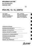
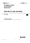
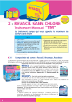
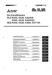
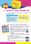
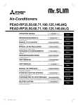
Back to Index
Air-Conditioners
INDOOR UNIT
D
PER L’UTENTE
VOOR DE GEBRUIKER
FÖR ANVÄNDAREN
PARA O UTILIZADOR
E
F
FOR USER
FÜR BENUTZER
POUR L’UTILISATEUR
PARA EL USUARIO
GB
PEH-P400, 500MYA
OPERATION MANUAL
BEDIENUNGSHANDBUCH
I
For safe and correct use, please read this operation manual thoroughly before operating the air-conditioner unit.
Zum sicheren und einwandfreien Gebrauch der Klimaanlage dieses Bedienungshandbuch vor Inbetriebnahme gründlich durchlesen.
MANUEL D’UTILISATION
MANUAL DE INSTRUCCIONES
NL
Pour une utilisation correcte sans risques, veuillez lire le manuel d’utilisation en entier avant de vous servir du climatiseur.
Lea este manual de instrucciones hasta el final antes de poner en marcha la unidad de aire acondicionado para garantizar un uso seguro y correcto.
BEDIENINGSHANDLEIDING
SW
ISTRUZIONI DI FUNZIONAMENTO
Leggere attentamente questi istruzioni di funzionamento prima di avviare l’unità, per un uso corretto e sicuro della stessa.
Voor een veilig en juist gebruik moet u deze bedieningshandleiding grondig doorlezen voordat u de airconditioner gebruikt.
MANUAL DE OPERAÇÃO
Para segurança e utilização correctas, leia atentamente o manual de operação antes de pôr a funcionar a unidade de ar condicionado.
P
DRIFTSMANUAL
Läs denna driftsmanual noga för säkert och korrekt bruk innan luftkonditioneringen används.
2
[Fig. 2.0.1]
[Fig. 2.0.2]
B
C
B
A
A
Air outlet
B
Air inlet
C
Air filter
TEMP.
ON/OFF
A
3
5
A
Wireless remote controller (option)
B
Remote controller
[Fig. 5.0.1]
[Fig. 3.0.1]
4
GB
1
˚C
B
CLOCK
AMPM
2
AMPM
C
TOO
3COOL
D
TOO
ON/OFF WARM
MODE
FAN
AUTO STOP
VANE
AUTO START
CHECK LOUVER
TEST RUN
P
E
I
SW
NL
F
SET
2
CLOCK
D
A
h
min
RESET
6
5
A
Air outlet
C Air filter
B
Air inlet
D Air filter handle
Contents
1. Safety precautions ......................................................................................
1.1. Installation .................................................................................
1.2. During operation ........................................................................
1.3. Disposing of the unit ..................................................................
2. Names and functions of various parts ........................................................
3. Operation ....................................................................................................
How to use the wireless remote controller (option) ...............................
3.1. Switching the unit ON/OFF ........................................................
3.2. Mode select ...............................................................................
3.3. Selecting a temperature TEMP. ................................................
3.4. Selecting a fan speed
........................................................
3
3
4
4
4
5
5
7
7
7
7
3.5.
3.6.
3.7.
4.
5.
6.
7.
8.
Setting the day of the week and time ........................................ 7
Using the timer .......................................................................... 8
Locking the remote controller buttons
(Operation function limit controller) ......................................... 11
3.8. Other indications ..................................................................... 11
The smart way to use ............................................................................... 12
Caring for the machine ............................................................................. 12
Troubleshooting ......................................................................................... 13
Installation and transferring works, and checking ..................................... 14
Specifications ............................................................................................ 14
1. Safety precautions
•
Warning:
Describes precautions that should be observed to avoid the risk of injury or
death to the user.
Caution:
Describes precautions that should be observed to prevent damage to the
unit.
Symbols put on the unit
: Indicates an action that must be avoided.
: Indicates that important instructions must be followed.
The outdoor unit must be installed on a stable, level surface, in a place
where there is no accumulation of snow, leaves or rubbish.
Do not stand on, or place any items on the unit. You may fall down or the
item may fall, causing injury.
Caution:
The outdoor unit should be installed in a location where air and noise emitted by the unit will not disturb the neighbours.
2) Indoor unit
Warning:
The indoor unit should be securely installed. If the unit is loosely mounted, it
may fall, causing injury.
3) Remote controller
: Indicates a part which must be grounded.
: Indicates that caution should be taken with rotating parts. (This symbol is
displayed on the main unit label.) <Color: yellow>
GB
Warning:
•
D
Symbols used in the text
1) Outdoor unit
F
s Before operating the unit, make sure you read all the “Safety
precautions”.
s “Safety precautions” lists important points about safety.
Please be sure to follow them.
Warning:
The remote controller should be installed in such a way that children cannot
play with it.
: Beware of electric shock. (This symbol is displayed on the main unit label.)
Warning:
safe place for easy reference whenever a question arises. If the unit is
going to be operated by another person, make sure that this manual is
given to him or her.
Warning:
•
•
•
•
•
•
The unit should not be installed by the user. Ask the dealer or an authorized company to install the unit. If the unit is installed improperly, water
leakage, electric shock or fire may result.
Use only accessories authorized by Mitsubishi Electric and ask your
dealer or an authorized company to install them. If accessories are installed improperly, water leakage, electric shock or fire may result.
The Installation Manual details the suggested installation method. Any
structural alteration necessary for installation must comply with local
building code requirements.
Never repair the unit or transfer it to another site by yourself. If repair is
performed improperly, water leakage, electric shock or fire may result. If
you need to have the unit repaired or moved, consult your dealer.
The appliance is not intended for use by young children or infirm persons without supervision.
Young children should be supervised to ensure that they do not play
with the appliance.
5) Power line, fuse or circuit breaker
SW
s After you have read this manual, keep it and the Installation Manual in a
Warning:
•
•
•
Make sure that the unit is powered by a dedicated line. Other appliances
connected to the same line could cause an overload.
Make sure that there is a main power switch.
Be sure to adhere to the unit’s voltage and fuse or circuit breaker ratings.
Never use a piece of wire or a fuse with a higher rating than the one
specified.
I
1.1. Installation
Caution:
Make sure that the drain hose is installed so that drainage can go ahead
smoothly. Incorrect installation may result in water leakage, causing damage to furniture.
6) Grounding
Caution:
•
•
The unit must be properly grounded. Never connect the grounding wire
to a gas pipe, water pipe, lightning conductor or telephone grounding
wire. If the unit is not grounded properly, electric shock may result.
Check frequently that the ground wire from the outdoor unit is properly
connected to both the unit’s ground terminal and the grounding electrode.
E
Carefully read the labels affixed to the main unit.
NL
4) Drain hose
P
<Color: yellow>
3
1.2. During operation
In case of failure
Warning:
Caution:
•
•
•
•
•
Do not use any sharp object to push the buttons, as this may damage the
remote controller.
Do not twist or tug on the remote controller cord as this may damage the
remote controller and cause malfunction.
Never remove the upper case of the remote controller. It is dangerous to
remove the upper case of the remote controller and touch the printed
circuit boards inside. Doing so can result in fire and failure.
Never wipe the remote controller with benzene, thinner, chemical rags,
etc. Doing so can result in discoloration and failure. To remove heavy
stains, soak a cloth in neutral detergent mixed with water, wring it out
thoroughly, wipe the stains off, and wipe again with a dry cloth.
Never block or cover the indoor or outdoor unit’s intakes or outlets. Tall
items of furniture underneath the indoor unit, or bulky items such as
large boxes placed close to the outdoor unit will reduce the unit’s efficiency.
Warning:
•
GB
•
•
Do not splash water over the unit and do not touch the unit with wet
hands. An electric shock may result.
Do not spray combustible gas close to the unit. Fire may result.
Do not place a gas heater or any other open-flame appliance where it will
be exposed to the air discharged from the unit. Incomplete combustion
may result.
Warning:
•
D
•
•
F
•
•
•
Do not remove the front panel or the fan guard from the outdoor unit
when it is running. You could be injured if you touch rotating, hot or highvoltage parts.
Never insert fingers, sticks etc. into the intakes or outlets, otherwise injury may result, since the fan inside the unit rotates at high speed. Exercise particular care when children are present.
If you detect odd smells, stop using the unit, turn off the power switch
and consult your dealer. Otherwise, a breakdown, electric shock or fire
may result.
When you notice exceptionally abnormal noise or vibration, stop operation, turn off the power switch, and contact your dealer.
Do not over-cool. The most suitable inside temperature is one that is
within 5°C of the outside temperature.
Do not leave handicapped people or infants sitting or standing in the
path of the airflow from the air-conditioner. This could cause health problems.
•
•
•
•
Never remodel the air conditioner. Consult your dealer for any repair service. Improper repair work can result in water leakage, electric shock, fire,
etc.
If the remote controller displays an error indication, the air conditioner
does not run, or there is any abnormality, stop operation and contact
your dealer. Leaving the unit as it is under such conditions can result in
fire or failure.
If the power breaker is frequently activated, get in touch with your dealer.
Leaving it as it is can result in fire or failure.
If the refrigeration gas blows out or leaks, stop the operation of the air
conditioner, thoroughly ventilate the room, and contact your dealer. Leaving the unit as it is can result in accidents due to oxygen deficiency.
When the air conditioner is not to be used for a long
time
•
•
•
If the air conditioner is not to be used for a long time due to a seasonal
change, etc., run it for 4 - 5 hours with the air blowing until the inside is
completely dry. Failing to do so can result in the growth of unhygienic,
unhealthy mold in scattered areas throughout the room.
When it is not to be used for an extended time, keep the [power supply]
turned OFF.
If the power supply is kept on, several watts or several tens of watts will
be wasted. Also, the accumulation of dust, etc., can result in fire.
Keep the power switched ON for more than 12 hours before starting operation. Do not turn the power supply OFF during seasons of heavy use.
Doing so can result in failure.
1.3. Disposing of the unit
Warning:
When you need to dispose of the unit, consult your dealer. If pipes are removed incorrectly, refrigerant (fluorocarbon gas) may blow out and come
into contact with your skin, causing injury. Releasing refrigerant into the
atmosphere also damages the environment.
NL
Caution:
•
•
Do not direct the airflow at plants or caged pets.
Ventilate the room frequently. If the unit is operated continuously in a
closed room for a long period of time, the air will become stale.
I
SW
2. Names and functions of various parts
Indoor unit
Remote Controller
•
Air inlet: Sucks the ambient air in.
•
•
Filter: The filter built into the unit as standard is a simple filter to remove visible
dust and dirt. If air purification is one of the conditions required for use, consult
with your dealer. (For details on how to clean, refer to page 12.)
•
Air outlet: Blows the air back out into the room.
PEH-P-MYA series
[Ceiling concealed type]
[Fig. 2.0.1] (P.2)
P
E
A
4
Air outlet
B
Air inlet
C
Air filter
Check out your remote controller.
Different controllers are used for different systems.
[Fig. 2.0.2] (P.2)
A
Wireless remote controller (option)
B
Remote controller
3. Operation
Drying (dehumidifying)
mode
: Disabled in the heating
The drying mode efficiently reduces the humidity in the room so that the room
temperature is not lowered excessively. When the selected room temperature is
reached in the Low setting, the airflow will stop for ten minutes and then will resume
for three minutes to keep the humidity low.
How to use the wireless remote controller
(option)
Replacing the Batteries and how to set the current time
[Fig. 3.0.1] (P.2)
If no signal is transmitted and the indoor unit’s lamp does not light up even if the
remote controller is operated, the batteries may have run out, so replace them with
new ones as described below.
1 Remove the front lid.
Heating
2 Replace the batteries with alkali batteries (size AAA). Make sure that the batteries are installed in the correct direction. (Insert the minus pole of the batteries first.)
•
The air conditioner works to heat the room to the selected temperature.
3 Reattach the front lid.
•
When selecting the heating mode, a desired room temperature must be set to
avoid any cool air. The fan will gradually increase the airflow delivery up to a
selected rate.
4 Press the RESET button using a thin stick.
When the room temperature reaches the selected temperature and the compressor stops, the fan will deliver a gentle airflow.
6 Press the CLOCK button using a thin stick and close the front lid.
If you are not going to use the unit for a long period of time, remove the batteries to
prevent damage which may occur due to leakage of electrolyte.
Caution:
Ventilation will not be displayed when not available (settings cannot be specified).
•
•
When ventilation is selected it will operate in all modes.
•
Note:
The airflow settings cannot be changed on the main unit.
•
F
•
NL
Ventilation
Signal from the WIRELESS REMOTE CONTROLLER may not be received
by the indoor unit installed in a room with fluorescent lamps using cyclic
ignition stabilizer of high voltage pulse or intermittent oscillator. If fluorescent lamps are to be newly installed, consult your local dealer.
If other air conditioner or electric appliance are effected due to operation
of the WIRELESS REMOTE CONTROLLER or vice versa, install the air
conditioner at some distance from others or consult your dealer.
Install the air conditioner in a place free of dust, high temperature, vibration and shock.
Do not cover the REMOTE CONTROLLER.
SW
•
I
The air conditioner automatically goes into the cooling or heating mode to keep the
room at the selected temperature.
button to set the current time.
E
Automatic (cooling / heating)
and
P
•
min
h
5 Press the
GB
The air conditioner works to cool the room to the selected temperature.
The fan blows air continuously at the selected speed.
D
Cooling
5
Remote controller-Button
8
1
9
TEMP.
2
MENU
3
BACK
Opening the door.
ON/OFF
MONITOR/SET
PAR-21MAA
ON/OFF
FILTER
DAY
CHECK TEST
OPERATION
CLOCK
0
CLEAR
A
B
C
4
GB
1
0
Filter
A
Test Run button
Up
B
Check button (Clear button)
C
Airflow Up/Down button
Timer Menu button (Monitor/Set button)
3
Mode button (Return button)
4
Set Time buttons
Back
5
Timer On/Off button (Set Day button)
6
Louver button (
Operation button)
To preceding operation number.
Ventilation button (
Operation button)
To next operation number.
ON/OFF button
9
Fan Speed button
F
8
button (<Enter> button)
Notes:
• If you press a button for a feature that is not installed at the indoor unit,
the remote controller will display the “Not Available” message.
• If you are using the remote controller to drive multiple indoor units, this
message will appear only if the feature is not present at the parent unit.
• Never expose the remote controller to direct sunlight. Doing so can result in the erroneous measurement of room temperature.
• Never place any obstacle around the lower right-hand section of the remote controller. Doing so can result in the erroneous measurement of
room temperature.
Ahead
D
67
Down
Set Temperature buttons
2
7
5
B
A
Remote controller-Display
TIME SUN MON TUE WED THU FRI SAT
TIMER
Hr
ON
C
AFTER
NL
˚F˚C
SW
A
G H I JK L
K
Day-of-Week
Shows the current day of the week.
Time/Timer Display
Shows the current time, unless the simple or Auto Off timer is set.
If the simple or Auto Off timer is set, shows the time remaining.
B
I
C
D
Temperature Setting
Up/Down Air Direction indicator
shows the direction of the outcoming airflow.
“One Hour Only” indicator
Displayed if the airflow is set to weak and downward during COOL or DRY mode. (Operation varies according to model.)
The indicator goes off after one hour, at which time the airflow direction also changes.
I
Louver display
Indicates the action of the swing louver. Does not appear if the louver is stationary.
J
Appears when the unit is running in Ventilation mode.
M
Fan Speed indicator
Shows the selected fan speed.
N
“Locked” indicator
Indicates that remote controller buttons have been locked.
O
“Clean The Filter” indicator
P
Timer indicators
The indicator comes on if the corresponding timer is set.
The indicator
H
Ventilation indicator
“Timer Is Off” indicator
Shows the target temperature.
G
(Power On indicator)
Comes on when it is time to clean the filter.
Indicates that the timer is off.
F
M
“Centrally Controlled” indicator
Indicates that operation of the remote controller has been prohibited by a main controller.
E
L
Identifies the current operation
Shows the operating mode, etc.
* Multilanguage display is supported.
O
P
Indicates that the power is on.
“Sensor” indication
Displayed when the remote controller sensor is used.
E
WEEKLY
SIMPLE
AUTO OFF
ONLY1Hr.
F
P
FUNCTION
FILTER
˚F˚C
D
E
N
AFTER OFF
ERROR CODE
Room Temperature display
Shows the room temperature.
6
Note:
• For purposes of this explanation, all parts of the display are shown as lit.
During actual operation, only the relevant items will be lit.
2. When reaching room temperature of your choice
B
Both the compressor and indoor fan stop.
C
When stop continues for 10 minutes, the compressor and indoor fan are operated for 3 minutes to keep the humidity low.
D
3 B
1
˚C
˚C
C
SIMPLE
TEMP.
ON/OFF
3
2
A
1
MENU
2
BACK
PAR-21MAA
MONITOR/SET
ON/OFF
FILTER
DAY
CLOCK
CHECK TEST
OPERATION
CLEAR
For heating
Press the 2 [operation mode] button to bring up the “
HEAT” display.
Regarding displays during heating operation “DEFROST”
Displayed only during the defrosting operation.
“STAND BY”
Displayed from the start of heating operation until the moment warm air blows out.
For automatic (cooling/heating)
Press the 2 [operation mode] button to bring up the “
AUTO” display.
Before starting operation (wired remote controller
only)
•
Start running after the “PLEASE WAIT” display has disappeared. The “PLEASE
WAIT” display briefly appears on the B display (max. 3 minutes) when the
power is turned on and after a power failure. This does not indicate any failure
of the air conditioner.
•
During heating operation, even if the indoor unit is set to operation while the
outdoor unit is in defrosting operation, operation starts after the defrosting operation of the outdoor unit has ended.
3.1. Switching the unit ON/OFF
TEMP.
D
The selected temperature C is displayed.
The ON indicator A should light up.
Each time you press the button, the temperature value decreases by 1 °C.
s To increase the room temperature:
1. Press
button 3 to set the desired temperature.
The power supply should not be turned off while the air conditioner is in use.
This can cause the unit to break down.
•
Even if you press the ON/OFF button immediately after shutting down the operation in progress, the air conditioner will not start for about three minutes.
This is to prevent the internal components from being damaged.
•
If the operation stops due to a power failure, the unit will not automatically
restart until the power has been restored. Press the ON/OFF button to restart.
3.2. Mode select
Each time you press the button, the temperature value increases by 1 °C.
•
Available temperature ranges are as follows:
Cooling & Drying: 19 - 30 °C
Heating:
17 - 28 °C
Automatic:
19 - 28 °C
•
The display flashes either 8 °C - 39 °C to inform you if the room temperature D
is lower or higher than the displayed temperature.
NL
•
•
F
The selected temperature C is displayed.
The ON indicator A goes off.
3.4. Selecting a fan speed
The ON indicator A should light up.
) button 2 and select the operation
(COOL) Cooling mode
Fan speed : 1 stage
Display :
(High)
3.5. Setting the day of the week and time
(DRY)
Drying mode
(FAN)
Fan mode
(HEAT)
Heating mode
(AUTO)
Automatic (cooling/heating) mode
■ Use this screen to change the current day of the week and time setting.
Day of the Week &
Time display
I
1
For cooling
Press the 2 [operation mode] button and bring up the “
SW
1. If the unit is off, press the ON/OFF button 1 to turn it on.
s
3.3. Selecting a temperature
•
s To stop an operation:
1. Press the ON/OFF button 1 again.
B
•
•
s To decrease the room temperature:
1. Press
button 3 to set the desired temperature.
s To start an operation:
1. Press the ON/OFF button 1.
2. Press the operation mode (
mode.
•
When the air conditioner is used together with burners, thoroughly ventilate the area. Insufficient ventilation can result in accidents due to oxygen deficiency.
Never place a burner at a place where it is exposed to the airflow from the
air conditioner.
Doing so can result in imperfect combustion of the burner.
The microcomputer functions in the following cases:
Air does not blow out when heating starts.
- To prevent any cool air from escaping.
Wait a moment until the airflow comes out naturally.
GB
Caution:
•
TIME SUN
COOL” display.
˚C
˚C
•
TEMP.
DRY” display.
Dry operation cannot be carried out at a room temperature of less than 18 °C.
2
BACK
For fan
Press the 2 [operation mode] button and bring up the “
MENU
PAR-21MAA
FAN” display.
•
The fan operation functions to circulate the air in the room.
•
The temperature of the room cannot be set by fan operation.
Caution:
Never expose your body directly to cool air for a long time. Excessive exposure to cool air is bad for your health, and should therefore be avoided.
MONITOR/SET
ON/OFF
ON/OFF
FILTER
DAY
CLOCK
9
4
CHECK TEST
OPERATION
CLEAR
A
Note:
• It can be set regardless of the operation of the indoor unit.
• The day and time will not appear if clock use has been disabled at Function Selection of remote controller, refer to Installation Manual.
Dry operation
The dry is a microcomputer-controlled dehumidifying operation which controls excessive air-cooling according to the room temperature of your choice. (Not usable
for heating.)
1. Until reaching room temperature of your choice
The compressor and indoor fan function is linked motion according to the change
of the room temperature and automatically repeat ON/OFF.
7
P
Press the 2 [operation mode] button and bring up the “
E
For dry
s How to Set the Day of the Week and Time...
3 Day of the Week Setting
2
1. Press the
TIME SUN
4 Time Setting
Set Time button A to show display 2.
or
2. Press the Timer On/Off (Set Day) button 9 to set the day.
* Each press advances the day shown at 3 : Sun → Mon → ... → Fri → Sat.
3. Press the appropriate Set Time button A as necessary to set the time.
* As you hold the button down, the time (at 4) will increment first in minute
intervals, then in ten-minute intervals, and then in one-hour intervals.
GB
D
5. Press the Mode (Return) button 2 to complete the setting procedure. This will
return the display to the standard control screen, where 1 will now show the
newly set day and time.
Op No.
Sunday
No. 1
• 8:30
• ON
• 23 °C
No. 2
• 10:00
• OFF
Monday
···
Saturday
• 10:00
• OFF
• 10:00
• OFF
···
No. 8
F
<Operation 2 settings for
every day>
Turn off the air conditioner at 10:00.
Note:
By setting the day to “Sun Mon Tues Wed Thurs Fri Sat”, you can set the
same operation to be carried out at the same time every day.
(Example: Operation 2 above, which is the same for all days of the week.)
3.6. Using the timer
s Setting the Weekly Timer
This section explains how to set and use the timer. You can use Function Selection
of remote controller to select which of three types of timer to use: 1 Weekly timer,
2 Simple timer, or 3 Auto Off timer.
For information about how to set the Function Selection of remote controller, refer
to Installation Manual.
3.6.1.
Shows the time
setting
5
6
Shows the selected operation (ON or OFF)
* Does not appear if operation is not set.
SUN
ON
WEEKLY
Using the Weekly Timer
■ The weekly timer can be used to set up to eight operations for each day of the
week.
• Each operation may consist of any of the following: ON/OFF time together
with a temperature setting, or ON/OFF time only, or temperature setting only.
• When the current time reaches a time set at this timer, the air conditioner
carries out the action set by the timer.
■ Time setting resolution for this timer is 1 minute.
NL
<Operation 1 settings for
Sunday>
Start the air conditioner
at 8:30, with the temperature set to 23 °C.
Note:
• Remote controller is equipped with a simplified clock with a precision of
about + or - one minute per month.
˚C
Note:
*1. Weekly Timer/Simple Timer/Auto Off Timer cannot be used at the same
time.
*2. The weekly timer will not operate when any of the following conditions is
in effect.
The timer feature is off; the system is in an malfunction state; a test run
is in progress; the remote controller is undergoing self-check or remote
controller check; the user is in the process of setting a function ; the user
is in the process of setting the timer; the user is in the process of setting
the current day of the week or time; the system is under central control.
(Specifically, the system will not carry out operations (unit on, unit off, or
temperature setting) that are prohibited during these conditions.)
Operation No.
4
I
SW
• 10:00
• OFF
▲
Note:
• Your new entries at Steps 2 and 3 will be cancelled if you press the Mode
(Return) button 2 before pressing the Filter
button 4.
Setup Matrix
▲
4. After making the appropriate settings at Steps 2 and 3, press the Filter
button 4 to lock in the values.
2. Press the Timer Menu button B, so that the “Set Up” appears on the screen
(at 2).
(Note that each press of the button toggles the display between “Set Up”
and “Monitor”.)
3. Press the Timer On/Off (Set Day) button 9 to set the day. Each press advances the display at 3 to the next setting, in the following sequence: “Sun
Mon Tues Wed Thurs Fri Sat” → “Sun” → ... → “Fri” → “Sat” → “Sun Mon
Tues Wed Thurs Fri Sat”...
4. Press the
or
Operation button (7 or 8) as necessary to select
the appropriate operation number (1 to 8) 4.
* Your inputs at Steps 3 and 4 will select one of the cells from the matrix
illustrated below. (The remote-controller display at left shows how the
display would appear when setting Operation 1 for Sunday to the values
indicated below.)
2
3 Day Setting
SUN
ON
1
˚C
E
WEEKLY
TEMP.
MENU
BACK
ON/OFF
FILTER
DAY
CHECK TEST
CLOCK
OPERATION
A 9
78
3
1
B
4
0
CLEAR
P
PAR-21MAA
MONITOR/SET
ON/OFF
2
s How to Set the Weekly Timer
1. Be sure that you are at a standard control screen, and that the weekly timer
indicator 1 is shown in the display.
8
7
Shows the temperature setting
* Does not appear if temperature is not set.
5. Press the appropriate Set Time button A as necessary to set the desired
time (at 5).
* As you hold the button down, the time first increments in minute intervals, then in ten-minute intervals, and then in one-hour intervals.
6. Press the ON/OFF button 1 to select the desired operation (ON or OFF),
at 6.
* Each press changes the next setting, in the following sequence: No display (no setting) → “ON” → “OFF”
7. Press the appropriate Set Temperature button 3 to set the desired temperature (at 7).
* Each press changes the setting, in the following sequence: No display
(no setting) ⇔ 24 ⇔ 25 ⇔ ... ⇔ 29 ⇔ 30 ⇔ 12 ⇔ ... ⇔ 23 ⇔ No display.
(Available range: The range for the setting is 12 °C to 30 °C. The actual
range over which the temperature can be controlled, however, will vary
according to the type of the connected unit.)
8. After making the appropriate settings at Steps 5, 6 and 7, press the Filter
button 4 to lock in the values.
To clear the currently set values for the selected operation, press and quickly
release the Check (Clear) button 0 once.
* The displayed time setting will change to “—:—”, and the On/Off and
temperature settings will all disappear.
(To clear all weekly timer settings at once, hold down the Check (Clear)
button 0 for two seconds or more. The display will begin flashing, indicating that all settings have been cleared.)
Note:
Your new entries will be cancelled if you press the Mode (Return) button 2
before pressing the Filter
button 4.
If you have set two or more different operations for exactly the same time,
only the operation with the highest Operation No. will be carried out.
9. Repeat Steps 3 to 8 as necessary to fill as many of the available cells as
you wish.
10.Press the mode (Return) button 2 to return to the standard control screen
and complete the setting procedure.
11.To activate the timer, press the Timer On/Off button 9, so that the “Timer
Off” indication disappears from the screen. Be sure that the “Timer Off”
indication is no longer displayed.
* If there are no timer settings, the “Timer Off” indication will flash on the
screen.
9
Timer Settings
SUN
TIMER
ON
OFF
˚C
WEEKLY
1
1. Be sure that the weekly timer indicator is visible on the screen (at 1).
2. Press the Timer Menu button B so that “Monitor” is indicated on the screen
(at 8).
3. Press the Timer On/Off (Set Day) button 9 as necessary to select the day
you wish to view.
4. Press the
or
Operation button (7 or 8) as necessary to change
the timer operation shown on the display (at 9).
* Each press will advance to the next timer operation, in order of time setting.
5. To close the monitor and return to the standard control screen, press the
Mode (Return) button 2.
s To Turn Off the Weekly Timer
Press the Timer On/Off button 9 so that “Timer Off” appears at 0.
Note:
Your new settings will be cancelled if you press the Mode (Return) button 2
before pressing the Filter
button 4.
TIME SUN
˚C
˚C
0
WEEKLY
s To Turn On the Weekly Timer
Press the Timer On/Off button 9 so that the “Timer Off” indication (at 0) goes
dark.
TIME SUN
s Viewing the Current Simple Timer Settings
˚C
˚C
0
8. Press the Mode (Return) button 2 to return to the standard control screen.
9. Press the Timer On/Off button 9 to start the timer countdown. When the
timer is running, the timer value is visible on the display. Be sure that the
timer value is visible and appropriate.
WEEKLY
D
8
2. Press the Timer Menu button B, so that the “Set Up” appears on the screen
(at 2). (Note that each press of the button toggles the display between “Set
Up” and “Monitor”.)
3. Press the ON/OFF button 1 to display the current ON or OFF simple timer
setting. Press the button once to display the time remaining to ON, and
then again to display the time remaining to OFF. (The ON/OFF indication
appears at 3).
• “ON” timer: The air conditioner will start operation when the specified
number of hours has elapsed.
• “OFF” timer: The air conditioner will stop operation when the specified
number of hours has elapsed.
4. With “ON” or “OFF” showing at 3: Press the appropriate Set Time button A
as necessary to set the hours to ON (if “ON” is displayed) or the hours to
OFF (if “OFF” is displayed) at 4.
• Available Range: 1 to 72 hours
5. To set both the ON and OFF times, repeat Steps 3 and 4.
* Note that ON and OFF times cannot be set to the same value.
6. To clear the current ON or OFF setting: Display the ON or OFF setting (see
step 3) and then press the Check (Clear) button 0 so that the time setting
clears to “—” at 4. (If you want to use only an ON setting or only an OFF
setting, be sure that the setting you do not wish to use is shown as “—”.)
7. After completing steps 3 to 6 above, press the Filter
button 4 to lock in
the value.
GB
s How to View the Weekly Timer Settings
6 Timer Setting
5
TIMER
Hr
ON
AFTER OFF
■ The simple timer (start and stop) can be set only once within a 72-hour period.
The time setting is made in hour increments.
Note:
*1. Weekly Timer/Simple Timer/Auto Off Timer cannot be used at the same
time.
*2. The simple timer will not operate when any of the following conditions is
in effect.
The timer is off; the system is in malfunction state; a test run is in progress;
the remote controller is undergoing self-check or remote controller check;
the user is in the process of selecting a function; the user is in the process of setting the timer; the system is under central control. (Under these
conditions, On/Off operation is prohibited.)
SIMPLE
1
1. Be sure that the simple timer indicator is visible on the screen (at 1).
2. Press the Timer Menu button B, so that the “Monitor” appears on the screen
(at 5).
• If the ON or OFF simple timer is running, the current timer value will
appear at 6.
• If ON and OFF values have both been set, the two values appear alternately.
3. Press the Mode (Return) button 2 to close the monitor display and return
to the standard control screen.
F
■ You can set the simple timer in any of three ways.
• Start time only:
The air conditioner starts when the set time has elapsed.
• Stop time only:
The air conditioner stops when the set time has elapsed.
• Start & stop times: The air conditioner starts and stops at the respective
elapsed times.
NL
Using the Simple Timer
s To Turn Off the Simple Timer...
Press the Timer On/Off button 9 so that the timer setting no longer appears on the
screen (at 7).
7
SW
3.6.2.
˚C
˚C
SIMPLE
I
s To Turn On the Simple Timer...
Press the Timer On/Off button 9 so that the timer setting becomes visible at 7.
Hr
7
ON
AFTER
SIMPLE
TEMP.
1
ON/OFF
Hr
ON
AFTER
PAR-21MAA
2
ON/OFF
FILTER
DAY
MONITOR/SET
CHECK TEST
OPERATION
CLOCK
˚C
˚C
SIMPLE
CLEAR
E
MENU
BACK
B
4
0
A 9
s How to Set the Simple Timer
4
Hr
Timer Setting
3
ON
AFTER
SIMPLE
1
P
2
Action (On or Off)
* “— —” is displayed if
there is no setting.
1. Be sure that you are at a standard control screen, and that the simple timer
indicator is visible in the display (at 1).
When something other than the Simple Timer is displayed, set it to SIMPLE
TIMER using the function selection of remote controller (see Installation
Manual).
9
When something other than the Auto Off Timer is displayed, set it to AUTO
OFF TIMER using the function selection of remote controller (see Installation Manual).
2. Hold down the Timer Menu button B for 3 seconds, so that the “Set Up”
appears on the screen (at 2).
(Note that each press of the button toggles the display between “Set Up”
and “Monitor”.)
3. Press the appropriate Set Time button A as necessary to set the OFF time
(at 3).
4. Press the Filter
button 4 to lock in the setting.
Examples
If ON and OFF times have both been set at the simple timer, operation and display
are as indicated below.
Example 1:
Start the timer, with ON time set sooner than OFF time
ON Setting:
3 hours
OFF Setting: 7 hours
Hr
ON
AFTER
Display shows the timer’s ON setting (hours
remaining to ON).
At Timer Start
SIMPLE
▲
Display changes to
show the timer’s OFF
setting (hours remaining to OFF). The time
displayed is OFF setting (7 hours) – ON
setting (3 hours) = 4
hours.
Hr
AFTER OFF
At 3 hours after
timer start
˚C
˚C
SIMPLE
▲
At 7 hours after The air conditioner
goes off, and will retimer start
GB
SIMPLE
Note:
Your entry will be cancelled if you press the Mode (Return) button 2 before
button 4.
pressing the Filter
5. Press the Mode (Return) button 2 to complete the setting procedure and
return to the standard control screen.
6. If the air conditioner is already running, the timer starts countdown immediately. Be sure to check that the timer setting appears correctly on the
display.
s Checking the Current Auto Off Timer Setting
4
main off until someone
restarts it.
5
TIMER
Example 2:
Start the timer, with OFF time is sooner than ON time
ON Setting:
5 hours
OFF Setting: 2 hours
AFTER
Display shows the timer’s OFF setting
(hours remaining to
OFF).
Display changes to
show the timer’s ON
setting (hours remaining to ON). The time
displayed is ON setting (5 hours) – OFF
setting (2 hours) = 3
hours.
At Timer Start
D
SIMPLE
▲
Hr
At 2 hours after
timer start
ON
AFTER
SIMPLE
▲
F
s To Turn Off the Auto Off Timer...
● Hold down the Timer On/Off button 9 for 3 seconds, so that “Timer Off” appears (at 6) and the timer value (at 7) disappears.
7
At 5 hours after The air conditioner
comes on, and will
timer start
continue to run until
˚C
˚C
SIMPLE
˚C
someone turns it off.
■ This timer begins countdown when the air conditioner starts, and shuts the air
conditioner off when the set time has elapsed.
■ Available settings run from 30 minutes to 4 hours, in 30-minute intervals.
Note:
*1. Weekly Timer/Simple Timer/Auto Off Timer cannot be used at the same
time.
*2. The Auto Off timer will not operate when any of the following conditions
is in effect.
The timer is off; the system is in malfunction state; a test run is in progress;
the remote controller is undergoing self-check or remote controller check;
the user is in the process of selecting a function; the user is in the process of setting the timer; the system is under central control. (Under these
conditions, On/Off operation is prohibited.)
˚C
6
AUTO OFF
● Alternatively, turn off the air conditioner itself. The timer value (at 7) will disappear from the screen.
7
AUTO OFF
s To Turn On the Auto Off Timer...
● Hold down the Timer On/Off button 9 for 3 seconds. The “Timer Off” indication disappears (at 6), and the timer setting comes on the display (at 7).
● Alternatively, turn on the air conditioner. The timer value will appear at 7.
7
I
NL
Using the Auto Off Timer
SW
3.6.3.
1
1. Be sure that the “Auto Off” is visible on the screen (at 1).
2. Hold down the Timer Menu button B for 3 seconds, so that “Monitor” is
indicated on the screen (at 4).
• The timer remaining to shutdown appears at 5.
3. To close the monitor and return to the standard control screen, press the
Mode (Return) button 2.
AFTER OFF
˚C
OFF
AUTO OFF
Hr
˚C
Timer Setting
AFTER
OFF
˚C
˚C
6
AFTER
AUTO OFF
E
TEMP.
MENU
BACK
PAR-21MAA
MONITOR/SET
AUTO OFF
OFF
Using the timer for wireless remote controller (option)
ON/OFF
ON/OFF
B
4
FILTER
DAY
•
CHECK TEST
OPERATION
CLOCK
1. Press the
CLEAR
AUTO STOP
or
AUTO START
OFF timer : D
A 9
P
2. Use the
sired time.
s How to Set the Auto Off Timer
2
3
h
is blinking.
and
min
buttons 5 to set the de-
3. Cancelling the timer.
Timer Setting
To cancel the OFF timer, press the
To cancel the ON timer, press the
AFTER
OFF
AUTO OFF
1
1. Be sure that you are at a standard control screen, and that the Auto Off
timer indicator is visible in the display (at 1).
10
D
is blinking.
ON timer : D
2
button 4 (TIMER SET).
Time can be set while the following symbol is blinking.
AUTO STOP
AUTO START
button 6.
button 6.
4
6
5
It is possible to combine both OFF and ON timers.
•
ON/OFF button of the remote controller during timer mode to
Pressing the
stop the unit will cancel the timers.
•
If the current time has not been set, the timer operation cannot be used.
3.8.2.
3.7. Locking the remote controller buttons
(Operation function limit controller)
■ If you wish, you can lock the remote controller buttons. You can use the Function Selection of remote controller to select which type of lock to use. (For
information about selecting the lock type, see Installation Manual).
Specifically, you can use either of the following two lock types.
1 Lock All Buttons:
Locks all of the buttons on the remote controller.
2 Lock All Except ON/OFF:
Locks all buttons other than the ON/OFF button.
Note:
The “Locked” indicator appears on the screen to indicate that buttons are
currently locked.
Flashing Mode Indicator
˚C
˚C
TEMP.
■ When mode switched after display flashes
Displayed when operation mode is restricted for each season by central controller, etc.
Use another operation mode.
3.8.3.
Flashing “Filter”
1
Lock Indicator
˚C
˚C
TIME SUN
TEMP.
FUNCTION
ON/OFF
1
PAR-21MAA
FILTER
DAY
CLOCK
4
CHECK TEST
OPERATION
■ When resetting “FILTER” display
When the [FILTER] button is pressed two times successively after cleaning the
filter, the display goes off and is reset.
CLEAR
3.8.4.
Flashing Error Codes
s How to Lock the Buttons
1. While holding down the Filter button 4, press and hold down the ON/OFF
button 1 for 2 seconds. The “Locked” indication appears on the screen (at
1), indicating that the lock is now engaged.
* If locking has been disabled in Function Selection of remote controller,
the screen will display the “Not Available” message when you press the
buttons as described above.
1
FUNCTION
˚C
˚C
•
If you press a locked button, the “Locked” indication (at 1) will blink on the
display.
1
FUNCTION
˚C
˚C
s How to Unlock the Buttons
1. While holding down the Filter button 4, press and hold down the ON/OFF
button 1 for 2 seconds—so that the “Locked” indication disappears from
the screen (at 1).
D
MONITOR/SET
ERROR CODE
ON/OFF
Indoor Unit’s
Refrigerant
Address
Error Code
ON lamp
(Flashing)
F
BACK
ON/OFF
ON/OFF
■ Indicates that the filter needs cleaning.
Clean the filter.
Indoor Unit No.
Alternating Display
If you have entered contact number to be called in the event of a problem, the screen
displays this number. (You can set this up under Function Selection of remote
controller. For information, refer to Installation Manual.)
● If the ON lamp and error code are both flashing: This means that the air conditioner is out of order and operation has been stopped (and cannot resume).
Take note of the indicated unit number and error code, then switch off the
power to the air conditioner and call your dealer or servicer.
NL
TEMP.
FILTER
SW
˚C
˚C
MENU
ON/OFF
■ When flashes continuously
Displayed when another indoor unit connected to the outdoor unit is already
operating in a different operation mode.
Match with the operation mode of the other indoor unit.
GB
•
ERROR CODE
˚C
˚C
ON/OFF
1
I
˚C
˚C
3.8. Other indications
Centrally Controlled
When the Check button is pressed:
˚C
˚C
TEMP.
ON/OFF
● Displayed when operation is controlled by central controller, etc.
Restricted operations are shown below.
• ON/OFF (including timer operation)
• Operation mode
• Set temperature
CALL:XXXX
XXX:XXX
P
3.8.1.
E
Error Code
● If only the error code is flashing (while the ON lamp remains lit): Operation is
continuing, but there may be a problem with the system. In this case, you should
note down the error code and then call your dealer or servicer for advice.
* If you have entered contact number to be called in the event of a problem,
push the Check button to display it on the screen. (You can set this up under
Function Selection of remote controller. For information, refer to Installation
Manual.)
ON/OFF
Note:
May also be individually restricted.
11
4. The smart way to use
Even minimal steps to care for your air conditioner can help make its use far
more effective in terms of air-conditioning effect, electricity charges, etc.
Prevent intrusion of heat during air-cooling
•
Set the right room temperature
•
In cooling operation, a temperature difference of about 5°C between indoors
and outdoors is optimum.
•
If the room temperature is raised by 1°C during air-cooling operation, about 10%
electric power can be saved.
•
Excessive cooling is bad for health. It also results in the waste of electric power.
Clean the filter thoroughly
GB
•
Carry out ventilation sometimes
•
Since the air periodically gets dirty in a room that is kept closed for a long time,
ventilation is sometimes necessary. When gas appliances are used together
with the air conditioner, special precautions must be taken. If the “LOSSNAY”
ventilation unit developed by our company is used, you can perform ventilation
with less waste. For details on this unit, consult with your dealer.
If the screen of the air filter becomes clogged, the airflow and air-conditioning
effect can be significantly reduced. Further, if the condition is left unattended,
failure can result. It is particularly important to clean the filter at the beginning
of the cooling and heating seasons. (When profuse dust and dirt have accumulated, clean the filter thoroughly.)
5. Caring for the machine
Always have filter maintenance performed by a service person.
Before care-taking, turn the power supply OFF.
Caution:
•
D
To prevent the intrusion of heat during cooling operation, provide a curtain or a
blind on the window to block out direct sunlight. Also, do not open the entrance
or exit except in cases of dire necessity.
•
Before you start cleaning, stop operation and turn OFF the power supply.
Remember that the fan is rotating inside at high speed, posing a serious
risk of injury.
Indoor units are equipped with filters to remove the dust of sucked-in air.
Clean the filters using the methods shown in the following sketches. (The
standard filter should normally be cleaned once a week, and the long-life
filter at the beginning of each season.)
Caution:
Never pour water or flammable sprays onto the air conditioner. Cleaning using
these methods can result in the failure of the air conditioner, electric shock,
or fire.
Replacement of filter
[Fig. 5.0.1] (P.2)
A
Air outlet
B
Air inlet
C
Air filter
D
Air filter handle
F
(1) The air filter is located at the air inlet (rear side of the unit).
How to clean
(2) Lift the air filter handles and pull the filter towards you.
•
Clear dust away lightly or clean it up with a vacuum cleaner. In the case of
severe staining, wash the filter in lukewarm water mixed with dissolved neutral
detergent or water, and then rinse off the detergent completely. After washing,
dry it and fix it back into place.
(3) If you are going to use an air inlet conduit. remove the air filter. In this case, an
air filter must be prepared locally and installed at the intake grille.
•
Do not dry the filter by exposing it to direct sunlight or warming it using
fire, etc. Doing so can result in the deformation of the filter.
Washing it in hot water (more than 50 degree C) can also result in deformation.
•
P
E
I
SW
NL
Caution:
12
6. Troubleshooting
● “PLEASE WAIT” is displayed in the remote controller.
• An automatic startup test is being performed (will last for about two minutes).
● A ticking noise is heard from inside of the unit.
• This sound is made when internal parts of the unit expand or contract when
the temperature changes.
● An error code is displayed in the remote controller.
• A self-diagnostic function is being performed to preserve the air conditioner.
* Do not attempt to make repairs yourself. Turn the main switch off and
contact the dealer from whom you bought the air conditioner. Provide him
or her with the name of the unit and the information displayed in the remote controller.
● An odor is detected in the room.
• This is caused when the unit expels odors that have been absorbed from the
walls, carpets, furniture or clothing.
● A white mist is expelled from the indoor unit.
• This may occur just after the unit is turned on when a high level of humidity is
present in the room.
● Water or moisture is expelled from the outdoor unit.
• This occurs to expel water or moisture that may have collected in the pipes
or around piping fixtures.
• This occurs to dispel water from the heat exchanger.
● The indicators of the remote controller do not light up when operated.
• Turn on the power switch. “ ” will be displayed.
●
indicator is displayed in the remote controller.
• The start and stop or operation mode or set temperature functions of the
remote controller are not available when the
indicator is lit.
● The start and stop functions are not available just after restarting the
unit.
• Wait about three minutes (operation has stopped to prevent damage to the
air conditioner).
● Unit does not start immediately.
• Wait until the unit restarts automatically. The compressor may hesitate resuming because a three-minute resume prevention circuit is incorporated in
the outdoor unit for protection of the compressor.
● No display appears on the wireless remote controller. Signals are not
received by the thin sensor unless sent from close up.
• The batteries are becoming weak.
Replace the batteries and press the reset button.
* If the display does not appear after replacing the batteries, make sure that
the (+, –) cells are aligned correctly.
GB
● There is a “swishing” noise that occurs from the unit when water flows.
• This sound is made when refrigerant inside of the unit is flowing or refilling.
D
● The unit stops operating before arriving at the set temperature in the
heating mode.
• Frost forms when the outdoor temperature is low and humidity is high. Wait
for about 10 minutes for the frost to melt.
● The unit stopped even though the start/stop button was not pushed.
• Is the timer on?
Press the start/stop button to restart the unit.
• Was a distant command sent from the remote controller?
Find out if the remote controller was used.
• Is the
indicator lit?
Find out if the remote controller was used.
● The unit does not blow air out right away in the heating mode.
• The unit is preparing to deliver warm air.
● The operating display of the wireless remote controller’s receiver is flashing.
• A self-diagnostic function is being performed to preserve the air conditioner.
* Do not attempt to make repairs yourself. Turn the main switch off and
contact the dealer from whom you bought the air conditioner. Provide him
or her with the name of the unit.
● The fan in the indoor unit does not operate.
• Check the over-current relay on the fan motor to determine whether it has
been tripped.
If the over-current relay has been tripped, reset it after eliminating the cause
of the problem (e.g. motor lock).
To reset the over-current relay, open the control box and press the green
claw on bottom-right of the relay until a click is heard. Release the claw and
check that it returns to its original position.
Note that if it is pressed too hard it will not return to its original position.
F
● Unit does not cool or heat very well.
• Clean the filter. (Dust and debris that collects in the filter will decrease airflow.)
• Check the temperature setting and adjust it if necessary.
• Increase the space surrounding the outdoor unit.
Is the air intake or air outlet blocked?
• Is a window or door open?
● The unit started even though the start/stop button was not pushed.
• Is the timer on?
Press the start/stop button to stop the unit.
• Was a distant command sent from the remote controller?
Find out if the remote controller was used.
• Is the
indicator lit?
Find out if the remote controller was used.
• Is the automatic (cooling/heating) mode selected?
Press the start/stop button to stop the unit.
NL
Before you call out a repair man, check the following table to see whether there is
a simple solution to your problem.
SW
If none of the above apply, turn the main switch off and contact the dealer from whom you bought the air-conditioner, telling him the model name and the nature of the
problem. Do not try to fix the unit yourself.
The operation lamp (on the main unit) flashes.
•
The switches do not work properly.
•
The circuit breaker trips frequently (or the fuse blows frequently).
•
Water has accidentally been splashed into the unit.
•
Water leaks from the unit.
•
Something is accidentally dropped into the air-conditioner.
•
An unusual noise is heard during operation.
The following do not indicate any malfunction:
Odours: smells such as tobacco or cosmetic odours may persist after they have been sucked into the unit.
Sound of liquid flowing inside indoor unit: this can occur during or after operation and is simply the sound of refrigerant being circulated inside the unit.
Ticking sound coming from indoor unit: this can occur when cooling or heating has just begun or has just stopped. It is caused by the indoor unit shrinking or expanding
slightly due to the change in temperature.
E
•
I
In any of the following cases, turn off the main power switch and contact your local dealer for service:
P
NOTE: The refrigerant charged in the air conditioner is safe. Refrigerant normally does not leak, however, if refrigerant gas leaks indoors, and comes into contact
with the fire of a fan heater, space heater, stove, etc., harmful substances will be generated.
Be sure to ask the service representative whether there is refrigerant leakage or not when repairs are carried out.
13
7. Installation and transferring works, and checking
Regarding place for installation
Consult with your dealer for details on installation and transferring the installation.
Regarding transfer of installation
•
Caution:
Never install the air conditioner where there is a risk of leakage of flammable
gas.
If gas leaks and accumulates around the unit, fire can result.
GB
Caution:
When moving or reinstalling the air conditioner, consult with your dealer.
Defective installation can result in electric shock, fire, etc.
Never install the air conditioner at the following place:
•
where there is much machine oil
•
near ocean and beach areas where there is much salt
•
where humidity is high
•
where there are hot springs nearby
•
where there is much sulfureted gas
•
where there is a high-frequency processing machinery (a high-frequency welder,
etc.)
•
where acid solution is frequently used
•
where special sprays are frequently used
•
Install the indoor unit horizontally. Otherwise, water leakage can result.
•
Take sufficient measures against noise when installing the air conditioners at
hospitals or communication-related businesses.
Regarding noise
If the air conditioner is used in any of the above-mentioned environments, frequent
operational failure can be expected. It is advisable to avoid these types of installation sites.
For further details, consult with your dealer.
D
When removing and reinstalling the air conditioner when you enlarge your
home, remodel, or move, consult with your dealer in advance to ascertain the
cost of the professional engineering work required for transferring the installation.
•
In installing work, choose a place that can fully bear the weight of the air conditioner, and where noise and vibration can be reduced.
•
Choose a place where cool or warm air and noise from the outdoor air outlet of
the air conditioner do not inconvenience the neighbours.
•
If any alien object is placed near the outdoor air outlet of the air conditioner,
decreased performance and increased noise can result. Avoid placing any
obstacles adjacent to the air outlet.
•
If the air conditioner produces any abnormal sound, consult with your dealer.
Maintenance and inspection
•
If the air conditioner is used throughout several seasons, the insides can get
dirty, reducing the performance.
Depending upon the conditions of usage, foul odors can be generated and
drainage can deteriorate due to dust and dirt, etc.
Regarding electrical work
Caution:
F
•
•
NL
•
The electrical work must be undertaken by a person who is qualified as
an electric engineer according to the [technical standard respecting electrical installation], [internal wiring rules], and the installation instruction
manual with the absolute use of exclusive circuits. The use of other products with the power source can result in burnt-out beakers and fuses.
Never connect the grounding wire to a gas pipe, water pipe, arrester, or
telephone grounding wire. For details, consult with your dealer.
In some types of installation sites, the installation of an earth leakage
breaker is mandatory. For details, consult with your dealer.
8. Specifications
Model
Item
E
I
SW
Voltage
Power source
Frequency
3N~ V
Hz
kW
Cooling capacity*1
kcal/h
kW
Heating capacity*1
kcal/h
Height
mm
Dimension
Width
mm
Depth
mm
Net weight
kg
Airflow rate
m3/min
Fan
External static pressure*2
Pa
Noise level
dB(A)
PEH-P400MYA
PEH-P500MYA
380, 400, 415
50
41.8
36,000
47.4
40,800
706
1,690
865
180
140
150, 170, 180
54, 55, 55
380, 400, 415
50
52.0
44,800
61.0
52,400
706
1,993
865
212
170
150, 160, 180
60, 60, 60
Notes: *1 Refer to the product nameplate attached to the unit for the electrical specifications.
*2 Rating conditions (cooling) Indoor: 27°C DB, 19°C WB
Outdoor: 35°C DB
*3 Rating conditions (heating) Indoor: 20°C DB
Outdoor: 7°C DB, 6°C DB
Operating range
P
Cooling
Heating
Maximum
Minimum
Maximum
Minimum
Indoor air intake temperature
32°C DB, 23°C WB
21°C DB, 15°C WB
27°C DB
20°C DB
Outdoor air intake temperature
46°C DB
–5°C DB
24°C DB, 18°C WB
–11°C DB, –12°C WB
Units should be installed by licensed electric contractor accordingly to local code requirement.
Noise level of outdoor unit
Model
Noise level dB(A)
14
PUH-P200MYA PUH-P250MYA
56
57
This product is designed and intended for use in the residential, commercial and light-industrial environment.
The product at hand is
based on the following
EU regulations:
•
•
Low Voltage Directive 73/23/EEC
Electromagnetic Compatibility Directive 89/
336/EEC
Please be sure to put the contact address/telephone number on
this manual before handing it to the customer.
HEAD OFFICE: MITSUBISHI DENKI BLDG., 2-2-3, MARUNOUCHI, CHIYODA-KU, TOKYO 100-8310, JAPAN
WT04602X01
Printed in Malaysia