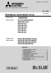
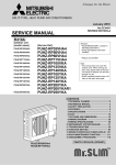
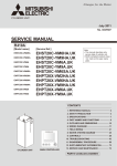
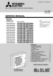
1
Contents
1 Specifications.........................................................B-2
Cylinder / Hydrobox
1.1 Combination table............................................................. B-2
1.2 Cylinder unit...................................................................... B-3
1.3 Hydrobox........................................................................... B-5
2 Outlines and dimensions.......................................B-6
2.1 Cylinder unit...................................................................... B-6
2.2 Hydrobox........................................................................... B-7
2.3 System configuration........................................................ B-8
2.4 Service access diagrams.................................................. B-9
3 Wiring diagrams....................................................B-10
3.1 Cylinder unit.................................................................... B-10
3.2 Hydrobox......................................................................... B-20
4 Water circuit diagrams.........................................B-25
4.1 Water quality and system preparation............................. B-28
4.2 Water pipe work................................................................ B-28
4.3 Performance curve external pressure................................. B-30
4.4 Safety device discharge arrangements........................... B-32
5 Performance curves.............................................B-34
5.1 Combination Performance.............................................. B-34
5.2 Heat time data (DHW mode)........................................... B-36
6 System Set Up.......................................................B-42
7 Troubleshooting....................................................B-54
7.1 Cylinder unit.................................................................... B-54
7.2 Hydrobox......................................................................... B-58
8 Supplementary information.................................B-61
Cylinder unit / Hydrobox
B-
1 Specifications
Cylinder unit / Hydrobox
1.1 Combination table
MODELS
POWER
INVERTER
ZUBADAN
POWER INVERTER
PACKAGE
ZUBADAN
SPLIT
TYPE
Heat pump
PUHZ-HRP200YKA
PUHZ-HRP125YHA2
PUHZ-HRP100YHA2
PUHZ-HRP100VHA2
PUHZ-HRP71VHA2
PUHZ-RP250YKA
PUHZ-RP200YKA
PUHZ-RP140YKA
PUHZ-RP140VKA
PUHZ-RP125YKA
PUHZ-RP125VKA
PUHZ-RP100YKA
PUHZ-RP100VKA
PUHZ-RP71VHA4
PUHZ-RP60VHA4
PUHZ-RP50VHA4
PUHZ-RP35VHA4
PUHZ-HW140YHA2
PUHZ-HW140VHA2
PUHZ-HW112YHA2
PUHZ-W85VHA2
TYPE
Cylinder / Hydrobox
Model name
R410A
PUHZ-W50VHA
REFRIGERANT
EHST20C-VM6HA
EHST20C-YM9HA
CYLINDER UNIT
EHST20C-VM6A
EHST20C-YM9A
EHST20C-VM6SA
EHPT20X-VM2HA
EHPT20X-VM6HA
EHPT20X-YM9HA
EHPT20X-VM6A
HYDRO BOX
EHPT20X-YM9A
EHSC-VM6A
EHSC-YM9A
EHPX-VM2A
: Combination is available.
Blank: Combination is NOT available.
B-
1 Specifications
Model name
Heat exchanger
Domestic hotwater tank
Booster heater (Phase)
Immersion heater
Solar circuit
Without package Height
Dimensions
Width
Depth
With package
Height
Width
Depth
Casing
Munsell
RAL code
Material
Product weight (empty)
Product weight (full)
Gross weight
Type of Installation
Power supply
mm
mm
mm
mm
mm
mm
kg
kg
kg
Ph
V
Hz
Booster heater Power supply
Ph
Heater
V
Hz
Capacity
kW
Heater step
Current
A
Breaker
A
Immersion
Power supply
Ph
heater
V
Hz
Capacity
kW
Current
A
Breaker
A
W
Water circulation Input
Speed
pump
W
Speed
(Primary circuit)
W
Speed
A
Current
Speed
A
Speed
A
Speed
Head difference Max.
m
20L/min
m
Performance curve
L/min
Flowrate
Primary circuit Max. *
L/min
Min. **
Heat exchanger Refrigerant - Primary circuit water
Primary circuit water - Domestic hot water
Coil: Surface area
m2
Coil: Length
m
Coil: Capacity
L
Coil: Material
Domestic
Volume
L
hot water tank
Material
-
* If the water flow rate exceeds maximum, the flow speed will be greater than 1.5 m/s, which could corrode the pipes.
** If the water flow rate is less than minimum, the flow switch will be activated.
*** The environment must be frost-free.
EHPT20X-VM2HA
EHPT20X-VM6HA
EHPT20X-YM9HA
EHPT20X-VM6A
EHPT20X-YM9A
X
X (1Phase)
X
X
X (1Phase)
X
X
X (3Phase)
X
X
X (1Phase)
X
X (3Phase)
1600
595
680
1850
660
800
1Y 9.2/0.2
RAL 9001
Pre-coated metal
119
332
136
Floor standing
~/N
230
50
~/N
230
50
2
1
9
16
~/N
230
50
3
13
16
95
125
149
0.46
0.58
0.65
7.1
6.3
1600
595
680
1850
660
800
1Y 9.2/0.2
RAL 9001
Pre-coated metal
119
332
136
Floor standing
~/N
230
50
~/N
230
50
6 (2/4/6)
3
26
32
~/N
230
50
3
13
16
95
125
149
0.46
0.58
0.65
7.1
6.3
27.7
7.1
Coil in tank
1.1*2
14*2
6.8*2
Stainless steel
200
Duplex 2304stainless
steel (EN10088)
L
12
Expansion vessel Volume
(Primary circuit) Charge pressure
MPa
0.1
Safety device
Primary circuit Control thermistor
°C
1~80
Pressure relief valve
MPa
0.3
5.5±1.0
Flow switch (Min. flow) L/min
BH manual reset thermostat °C
90
BH thermal Cut Off
°C
121
DHW tank
Control thermistor
°C
75
IH manual reset thermostat
°C
85
°C
90
Temperature & pressure
relief valve
MPa
0.7
Connections
Water
Primary circuit
mm
28
DHW circuit
mm
22
Solar circuit
mm
Refrigerant
Gas
mm
(R410A)
Liquid
mm
0~35
Operating ambient condition ***
10~30
Operating range Heating
Room temperature
25~60
Flow temperature
40~60
DHW
Max 70
Legionella prevention
Sound level (SPL)
dB(A)
28
1600
1600
595
595
680
680
1850
1850
660
660
800
800
1Y 9.2/0.2
1Y 9.2/0.2
RAL 9001
RAL 9001
Pre-coated metal
Pre-coated metal
119
118
332
331
136
135
Floor standing
Floor standing
~/N
~/N
230
230
50
50
3~
~/N
400
230
50
50
9 (3/6/9)
6 (2/4/6)
3
3
13
26
16
32
~/N
230
50
3
13
16
95
95
125
125
149
149
0.46
0.46
0.58
0.58
0.65
0.65
7.1
7.1
6.3
6.3
Refer to the following page
27.7
27.7
27.7
7.1
7.1
7.1
Coil in tank
Coil in tank
Coil in tank
1.1*2
1.1*2
1.1*2
14*2
14*2
14*2
6.8*2
6.8*2
6.8*2
Stainless steel
Stainless steel
Stainless steel
200
200
200
Duplex 2304stainless Duplex 2304stainless Duplex 2304stainless
steel (EN10088)
steel (EN10088)
steel (EN10088)
12
12
12
0.1
0.1
0.1
1~80
1~80
1~80
0.3
0.3
0.3
5.5±1.0
5.5±1.0
5.5±1.0
90
90
90
121
121
121
75
75
75
85
85
85
1.0
1.0
1.0
28
28
28
22
22
22
0~35
0~35
0~35
10~30
10~30
10~30
25~60
25~60
25~60
40~60
40~60
40~60
Max 70
Max 70
Max 70
28
28
28
1600
595
680
1850
660
800
1Y 9.2/0.2
RAL 9001
Pre-coated metal
118
331
135
Floor standing
~/N
230
50
3~
400
50
9 (3/6/9)
3
13
16
95
125
149
0.46
0.58
0.65
7.1
6.3
27.7
7.1
Coil in tank
1.1*2
14*2
6.8*2
Stainless steel
200
Duplex 2304stainless
steel (EN10088)
12
0.1
1~80
0.3
5.5±1.0
90
121
75
85
1.0
28
22
0~35
10~30
25~60
40~60
Max 70
28
B-
Cylinder / Hydrobox
1.2 Cylinder unit
Cylinder unit / Hydrobox
1 Specifications
Cylinder unit / Hydrobox
* If the water flow rate exceeds maximum, the flow speed will be greater than 1.5 m/s, which could corrode the pipes.
** If the water flow rate is less than minimum, the flow switch will be activated.
*** The environment must be frost-free.
Model name
Cylinder / Hydrobox
Heat exchanger
Domestic hotwater tank
Booster heater (Phase)
Immersion heater
Solar circuit
Without package Height
Dimensions
Width
Depth
With package
Height
Width
Depth
Casing
Munsell
RAL code
Material
Product weight (empty)
Product weight (full)
Gross weight
Type of Installation
Power supply
Heater
Booster heater
Immersion
heater
Power supply
Capacity
Heater step
Current
Breaker
Power supply
Capacity
Current
Breaker
Water circulation Input
Speed
pump
Speed
(Primary circuit)
Speed
Current
Speed
Speed
Speed
Head difference Max.
20L/min
Performance curve
Flowrate
Primary circuit Max. *
Min. **
Heat exchanger Refrigerant - Primary circuit water
Primary circuit water - Domestic hot water
Coil: Surface area
Coil: Length
Coil: Capacity
Coil: Material
Domestic
Volume
hot water tank
Material
mm
mm
mm
mm
mm
mm
kg
kg
kg
Ph
V
Hz
Ph
V
Hz
kW
A
A
Ph
V
Hz
kW
A
A
W
W
W
A
A
A
m
m
L/min
L/min
m2
m
L
L
EHST20C-VM6HA
EHST20C-YM9HA
EHST20C-VM6A
EHST20C-YM9A
EHST20C-VM6SA
X
X
X (1Phase)
X
X
X
X (3Phase)
X
X
X
X (1Phase)
X
X
X (3Phase)
X
X
X (1Phase)
1600
595
680
1850
660
800
1Y 9.2/0.2
RAL 9001
Pre-coated metal
131
346
148
Floor standing
~/N
230
50
~/N
230
50
6 (2/4/6)
3
26
32
~/N
230
50
3
13
16
95
125
149
0.46
0.58
0.65
7.1
6.3
1600
595
680
1850
660
800
1Y 9.2/0.2
RAL 9001
Pre-coated metal
131
346
148
Floor standing
~/N
230
50
3~
400
50
9 (3/6/9)
3
13
16
~/N
230
50
3
13
16
95
125
149
0.46
0.58
0.65
7.1
6.3
27.7
7.1
Plate
Coil in tank
1.1*2
14*2
6.8*2
Stainless steel
200
Duplex 2304stainless
steel (EN10088)
L
12
Expansion vessel Volume
(Primary circuit) Charge pressure
MPa
0.1
Safety device
Primary circuit Control thermistor
°C
1~80
Pressure relief valve
MPa
0.3
5.5±1.0
Flow switch (Min. flow) L/min
BH manual reset thermostat °C
90
BH thermal Cut Off
°C
121
DHW tank
Control thermistor
°C
75
IH manual reset thermostat
°C
85
°C
Temperature & pressure
relief valve
MPa
1.0
Connections
Water
Primary circuit
mm
28
DHW circuit
mm
22
Solar circuit
mm
Refrigerant
Gas
mm
15.88
(R410A)
Liquid
mm
9.52
0~35
Operating ambient condition ***
10~30
Operating range Heating
Room temperature
25~60
Flow temperature
40~60
DHW
Max 70
Legionella prevention
Sound level (SPL)
dB(A)
28
B-
1600
1600
595
595
680
680
1850
1850
660
660
800
800
1Y 9.2/0.2
1Y 9.2/0.2
RAL 9001
RAL 9001
Pre-coated metal
Pre-coated metal
130
130
345
345
147
147
Floor standing
Floor standing
~/N
~/N
230
230
50
50
~/N
3~
230
400
50
50
6 (2/4/6)
9 (3/6/9)
3
3
26
13
32
16
95
95
125
125
149
149
0.46
0.46
0.58
0.58
0.65
0.65
7.1
7.1
6.3
6.3
Refer to the following page
27.7
27.7
27.7
7.1
7.1
7.1
Plate
Plate
Plate
Coil in tank
Coil in tank
Coil in tank
1.1*2
1.1*2
1.1*2
14*2
14*2
14*2
6.8*2
6.8*2
6.8*2
Stainless steel
Stainless steel
Stainless steel
200
200
200
Duplex 2304stainless Duplex 2304stainless Duplex 2304stainless
steel (EN10088)
steel (EN10088)
steel (EN10088)
12
12
12
0.1
0.1
0.1
1~80
1~80
1~80
0.3
0.3
0.3
5.5±1.0
5.5±1.0
5.5±1.0
90
90
90
121
121
121
75
75
75
85
85
85
1.0
1.0
1.0
28
28
28
22
22
22
15.88
15.88
15.88
9.52
9.52
9.52
0~35
0~35
0~35
10~30
10~30
10~30
25~60
25~60
25~60
40~60
40~60
40~60
Max 70
Max 70
Max 70
28
28
28
X
1600
595
680
1850
660
800
1Y 9.2/0.2
RAL 9001
Pre-coated metal
131
346
148
Floor standing
~/N
230
50
~/N
230
50
6 (2/4/6)
3
26
32
95
125
149
0.46
0.58
0.65
7.1
6.3
27.7
7.1
Plate
Coil in tank
1.1+1.1 (Solar)
14+14 (Solar)
6.8+6.8 (Solar)
Stainless steel
200
Duplex 2304stainless
steel (EN10088)
12
0.1
1~80
0.3
5.5±1.0
90
121
75
85
1.0
28
22
22
15.88
9.52
0~35
10~30
25~60
40~60
Max 70
28
1 Specifications
Cylinder unit / Hydrobox
* If the water flow rate exceeds maximum, the flow speed will be greater than 1.5 m/s, which could corrode the pipes.
** If the water flow rate is less than minimum, the flow switch will be activated.
*** The environment must be frost-free.
Model name
EHPX-VM2A
Heat exchanger
Domestic hotwater tank
Booster heater (Phase)
Immersion heater
Solar circuit
Dimensions
Without package Height
Width
Depth
With package
Height
Width
Depth
Casing
Munsell
RAL code
Material
Product weight (empty)
Product weight (full)
Gross weight
Type of Installation
Power supply
Heater
Booster heater
Immersion
heater
Power supply
Capacity
Heater step
Current
Breaker
Power supply
Capacity
Current
Breaker
Water circulation Input
Speed
pump
Speed
(Primary circuit)
Speed
Current
Speed
Speed
Speed
Head difference Max.
20L/min
Performance curve
Flowrate
Primary circuit Max. *
Min. **
Heat exchanger Refrigerant - Primary circuit water
Primary circuit water - Domestic hot water
Coil: Surface area
Coil: Length
Coil: Capacity
Coil: Material
Domestic
Volume
hot water tank
Material
X (1Phase)
mm
mm
mm
mm
mm
mm
kg
kg
kg
Ph
V
Hz
Ph
V
Hz
kW
A
A
Ph
V
Hz
kW
A
A
W
W
W
A
A
A
m
m
L/min
L/min
m2
m
L
L
-
Volume
L
Charge pressure
MPa
Safety device
Primary circuit Control thermistor
°C
Pressure relief valve
MPa
Flow switch (Min. flow) L/min
BH manual reset thermostat °C
BH thermal Cut Off
°C
DHW tank
Control thermistor
°C
IH manual reset thermostat
°C
°C
Temperature & pressure
relief valve
MPa
Connections
Water
Primary circuit
mm
DHW circuit
mm
Solar circuit
mm
Refrigerant
Gas
mm
(R410A)
Liquid
mm
Operating ambient condition ***
Operating range Heating
Room temperature
Flow temperature
DHW
Legionella prevention
Sound level (SPL)
dB(A)
Expansion vessel
(Primary circuit)
800
530
360
990
600
560
1Y 9.2/0.2
RAL 9001
Pre-coated metal
39
44
52
Wall mounted
~/N
230
50
~/N
230
50
2
1
9
16
95
125
149
0.46
0.58
0.65
7.1
6.3
27.7
7.1
-
EHSC-VM6A
EHSC-YM9A
X
X
X (1Phase)
X (3Phase)
800
800
530
530
360
360
990
990
600
600
560
560
1Y 9.2/0.2
1Y 9.2/0.2
RAL 9001
RAL 9001
Pre-coated metal
Pre-coated metal
54
54
60
60
66
66
Wall mounted
Wall mounted
~/N
~/N
230
230
50
50
~/N
3~
230
400
50
50
6 (2/4/6)
9 (3/6/9)
3
3
26
13
32
16
95
95
125
125
149
149
0.46
0.46
0.58
0.58
0.65
0.65
7.1
7.1
6.3
6.3
Refer to the following page
27.7
27.7
7.1
7.1
Plate
Plate
-
-
-
-
10
0.1
1~80
0.3
5.5±1.0
90
121
28
0~35
10~30
25~60
28
10
0.1
1~80
0.3
5.5±1.0
90
121
28
15.88
9.52
0~35
10~30
25~60
28
10
0.1
1~80
0.3
5.5±1.0
90
121
28
15.88
9.52
0~35
10~30
25~60
28
Cylinder / Hydrobox
1.3 Hydrobox
B-
2 Outlines and dimensions
Cylinder unit / Hydrobox
2.1 Cylinder unit
595
G1/2
Main controller
100±20
Air vent
Pressure relief valve
79
680
445
Temperature and
pressure relief valve
and its access plate
(EXPT20X-VM2HA only)
30
Cylinder / Hydrobox
183
156
1
1600
50
950
1095
Terminal block
Front panel
<Left side>
Pipe description
Connection size/type
A
DHW outlet connection
22 mm/Compression
B
Cold water inlet connection
22 mm/Compression
C/D
Solar (ancillary heat source) connection
22 mm/Compression
E
Space heating return connection
28 mm/Compression
F
Space heating flow connection
28 mm/Compression
G
Flow from heat pump connection
(No plate heat exchanger)
28 mm/Compression
H
Return to heat pump connection
(No plate heat exchanger)
28 mm/Compression
J
Refrigerant (GAS)
(With plate heat exchanger)
15.88 mm/Flare
K
Refrigerant (LIQUID)
(With plate heat exchanger)
9.52 mm/Flare
L
Electrical cable inlets
—
* The leftmost hole is for
wireless receiver (option)
(PAR-WR41R-E)
D
E
47.1
0
550.2
541.1
522.8
492.2
470.8
Letter
C
<Right side>
<Front>
0
63.3
67.8
123
A
B
G/J
F
449.7
491.1
509.7
561.7
H/K
L
<Top>
B-
2 Outlines and dimensions
Cylinder unit / Hydrobox
2.2 Hydrobox
<EHSC> (Split model system)
55.5
100±5
110±5
264.5
590
800
Cylinder / Hydrobox
530
(233)
<Front>
<Side>
E
F
Letter
282
253
189
142
96
233
348
360
A
48
86
124
163
237
326
381
461
<View from below>
D
Pipe description
Connection size/type
A
Space heating/Indirect DHW cylinder (pri28 mm/Compression
mary) return connection
B
Space heating/Indirect DHW cylinder (pri28 mm/Compression
mary) flow connection
C
Refrigerant (Liquid)
9.52 mm/Flare
D
Refrigerant (Gas)
15.88 mm/Flare
E
Discharge pipe (by installer) from pressure G1/2” female (valve port
relief valve
within hydrobox casing)
F
Electrical cable inlets
C
B
<Rear>
—
*The leftmost inlet is for
wireless receiver (option)
<EHPX> (Packaged model system)
110±5
55.5
264.5
577
800
530
(233)
<Front>
E
F
A
<Side>
Letter
282
253
189
142
77
56
233
348
360
A
48
B
86
89
124
157
163
237
D
461
<View from below>
Pipe description
<Rear>
Connection size/type
Space heating/Indirect DHW cylinder (pri28 mm/Compression
mary) return connection
B
Flow connection from heat pump
28 mm/Compression
C
Return connection to heat pump
28 mm/Compression
D
Space heating/Indirect DHW cylinder (pri28 mm/Compression
mary) flow connection
E
Discharge pipe (by installer) from pressure G1/2” female (valve port
relief valve
within hydrobox casing)
F
Electrical cable inlets
C
—
*The leftmost inlet is for wireless receiver (option)
B-
2 Outlines and dimensions
Cylinder unit / Hydrobox
2.3 System configuration
Packaged model system
Split model system
EHPT20X-
EHST20C-
Model name
Plate heat exchanger
Plate heat exchanger
Cylinder / Hydrobox
Cylinder unit
Interconnecting
water pipes
Interconnecting
refrigerant pipes
Indoor cylinder unit
Outdoor heat pump unit
Indoor cylinder unit
Outdoor heat pump unit
Model name
EHPX-
EHSC-
Plate heat exchanger
Plate heat exchanger
Hydrobox
Interconnecting
water pipes
Interconnecting
refrigerant pipes
Indoor hydrobox
Outdoor heat pump unit
Indoor hydrobox
Outdoor heat pump unit
Important Parts of the Units - Points to Note
< Cylinder unit >
Cold water inlet connection
DHW outlet
connection
Solar (ancillary
heat source)
connection
Space heating
flow connection
Pressure relief
valve
Space heating
return connection
< Hydrobox >
EHPX (Package model system)
EHSC (Split model system)
Automatic air vent
Heat pump
connection
Plan view
Manometer
(Pressure gauge)
Main controller
Main controller
Main controller
Manometer
(Pressure gauge)
Manometer
(Pressure gauge)
Temperature and
pressure relief valve
*EHPT20X-VM2HA
ONLY
Space heating/
Indirect DHW
cylinder (primary)
return
connection
Space heating/
Indirect DHW
cylinder
(primary) flow
connection
Heat pump
connection Space heating/
Heat pump
Indirect DHW
cylinder (primary) connection
return
connection
Discharge pipe
from pressure
relief valve
View of base
Front elevation
B-
Space heating/
Indirect DHW cylinder
(primary) flow connection
Discharge pipe
from pressure
relief valve
View of base
2 Outlines and dimensions
Cylinder unit / Hydrobox
2.4 Service access diagrams
Hydrobox
Cylinder unit
Service access
Service access
Parameter
a
b
c (distance behind unit not visible
in Figure 2.5.1)
d
Dimension (mm)
300
150
10
Parameter
a
b
c
d
Dimension (mm)
200
150
500
500
Sufficient space MUST be left for the provision of discharge pipework as detailed in National and Local building regulations.
Sufficient space MUST be left for the provision of discharge pipework as detailed in National and Local building regulations.
a
a
b
b
b
b
d
c
d
<Figure 2.5.1>
Service access
The cylinder unit must be located indoors and in a frost-free environment,
for example in a utility room, to minimise heat loss from stored water.
<Figure 2.5.2>
Service access
The hydrobox must be located indoors and in a frost-free environment, for
example in a utility room.
B-
Cylinder / Hydrobox
500
3 Wiring diagrams
Cylinder unit / Hydrobox
3.1 Cylinder unit
EHST20C-VM6HA
Cylinder / Hydrobox
* See Page B-19.
B-10
3 Wiring diagrams
Cylinder unit / Hydrobox
Cylinder / Hydrobox
EHST20C-YM9HA
* See Page B-19.
B-11
3 Wiring diagrams
Cylinder unit / Hydrobox
EHST20C-VM6A
EHST20C-VM6SA
Cylinder / Hydrobox
* See Page B-19.
B-12
3 Wiring diagrams
Cylinder unit / Hydrobox
Cylinder / Hydrobox
EHST20C-YM9A
* See Page B-19.
B-13
3 Wiring diagrams
Cylinder unit / Hydrobox
EHPT20X-VM2HA
Cylinder / Hydrobox
* See Page B-19.
B-14
3 Wiring diagrams
Cylinder unit / Hydrobox
Cylinder / Hydrobox
EHPT20X-VM6HA
* See Page B-19.
B-15
3 Wiring diagrams
Cylinder unit / Hydrobox
EHPT20X-YM9HA
Cylinder / Hydrobox
* See Page B-19.
B-16
3 Wiring diagrams
Cylinder unit / Hydrobox
Cylinder / Hydrobox
EHPT20X-VM6A
* See Page B-19.
B-17
3 Wiring diagrams
Cylinder unit / Hydrobox
EHPT20X-YM9A
Cylinder / Hydrobox
* See Page B-19.
B-18
3 Wiring diagrams
Cylinder unit / Hydrobox
Dip switch setting (Cylinder unit)
Default (Indoor unit Ref.)
OFF
SW1-3
WITHOUT DHW tank
WITH DHW tank
SW1-4
Immersion heater
WITHOUT immersion heater
WITH immersion heater
SW1-5
Booster heater
WITHOUT booster heater
WITH booster heater
OFF:EH*****-*M**
ON :EH*****-*M*H*
ON
SW1-6
Booster heater function
For heating only
For heating and DHW
ON
SW1-7
Outdoor unit type
Split type
Packaged type
SW1-8
Wireless remote controller
OFF:EHS****-*M**
ON :EHP****-*M**
OFF
OFF:EHS****-*M** ( 1)
ON :EHP****-*M**
ON
SW2-1
WITHOUT wireless remote con- WITH wireless remote controller
troller
Room thermostat input (IN1) logic change Operation stop at thermostat short Operation stop at thermostat open
OFF
SW2-2
Flow switch input (IN2) logic change
Failure detection at short
Failure detection at open
ON
SW2-3
Booster heater capacity restriction
Inactive
Active
OFF
ON: EHPT20X-VM2HA
OFF
SW2-6
—
—
Automatic switch to backup heater only op- Inactive
eration (When outdoor unit stops by error)
—
—
OFF
Active ( 3)
—
—
OFF
SW2-7
—
—
—
OFF
SW2-8
—
—
—
OFF
SW3-1
—
—
—
OFF
SW3-2
—
—
—
OFF
SW3-3
—
—
—
OFF
SW3-4~8
—
—
—
OFF
—
OFF
SW4-1~4
SW4-5
SW4-6
Notes:
—
60 °C
SW2-4
SW4
ON
—
55 °C
SW2-5
SW3
OFF
—
Heat pump maximum outlet water
temperature
DHW tank
SW1-2
SW2
Function
Cylinder / Hydrobox
Dip switch
SW1
SW1-1
—
Emergency mode (Heater only operation)
—
—
Normal
—
Emergency mode (Heater only operation) OFF ( 2)
(To be activated only when powered ON)
OFF
—
1. For packaged model system, the max outlet water temperature is always 60°C so default Dip switch SW1-2 is ON.
For split model system, the max outlet water temperature is usually 55°C except in the case of PUHZ-HRP outdoor model where the max
outlet water temperature is 60°C and DIP switch SW1-2 should be changed to ON.
2. If emergency mode is no longer required, please turn off both outdoor and indoor unit power supply before returning SW4-5 to OFF position.
3. For safety reasons, this function is not available for certain errors. (System operation must be stopped and only pump keeps running.)
External output (OUT11) will be available.
B-19
3 Wiring diagrams
Cylinder unit / Hydrobox
3.2 Hydrobox
EHSC-VM6A
Cylinder / Hydrobox
* See Page B-23.
B-20
3 Wiring diagrams
Cylinder unit / Hydrobox
Cylinder / Hydrobox
EHSC-YM9A
* See Page B-23.
B-21
3 Wiring diagrams
Cylinder unit / Hydrobox
EHPX-VM2A
Cylinder / Hydrobox
* See Page B-23.
B-22
3 Wiring diagrams
Cylinder unit / Hydrobox
Dip switch setting (Hydrobox)
Dip switch
60 °C
SW1-3
WITHOUT DHW tank
WITH DHW tank
OFF: EHSC ( 1)
ON : EHPX
OFF
SW1-4
Immersion heater
WITHOUT immersion heater
WITH immersion heater
OFF
SW1-5
Booster heater
WITHOUT booster heater
WITH booster heater
ON
SW1-6
Booster heater function
For heating only
For heating and DHW
OFF
SW1-7
Outdoor unit type
Split type
Packaged type
WITHOUT wireless remote controller WITH wireless remote controller
OFF: EHSC
ON : EHPX
OFF
SW1-8
Wireless remote controller
SW2-1
Room thermostat input (IN1) logic change
Operation stop at thermostat short
Operation stop at thermostat open
OFF
SW2-2
Flow switch input (IN2) logic change
Failure detection at short
Failure detection at open
ON
SW2-3
Booster heater capacity restriction
Inactive
Active
OFF: EHSC
ON : EHPX-VM2A
OFF
SW2-5
SW4
—
—
Automatic switch to backup heater only op- Inactive
eration (When outdoor unit stops by error)
—
OFF
Active ( 3)
SW2-6
—
—
—
OFF
SW2-7
—
—
—
OFF
SW2-8
—
—
—
OFF
SW3-1
—
—
—
OFF
SW3-2
—
—
—
OFF
SW3-3
—
—
—
OFF
SW3-4~8
—
—
—
OFF
SW4-1~4
—
—
—
OFF
SW4-5
SW4-6
Notes:
—
55 °C
SW2-4
SW3
—
Default
(Indoor unit Ref.)
OFF
Heat pump maximum outlet water
temperature
DHW tank
SW1-2
SW2
—
SW1-1
ON
OFF
Cylinder / Hydrobox
SW1
Function
Emergency mode (Heater only operation)
Normal
—
—
Emergency mode (Heater only operation) OFF ( 2)
(To be activated only when powered ON)
OFF
—
1. For packaged model system, the max outlet water temperature is always 60°C so default Dip switch SW1-2 is ON.
For split model system, the max outlet water temperature is usually 55°C except in the case of PUHZ-HRP outdoor model where the max
outlet water temperature is 60°C and DIP switch SW1-2 should be changed to ON.
2. If emergency mode is no longer required, please turn off both outdoor and indoor unit power supply before returning SW4-5 to OFF position.
3. For safety reasons, this function is not available for certain errors. (System operation must be stopped and only pump keeps running.)
External output (OUT11) will be available.
Automatic switch to backup heater only operation
Back-up heater operation (*1) will automatically run when the indoor unit stops abnormally.
To enable the function, switch Dip SW 2-5 to ON.
During the back-up operation, an error code(s) and the contact number will be displayed alternately.
External output (OUT11) will be available.
To clear the fault(s), reset the power breakers on the indoor and outdoor units.
<Applicable error codes (*2)>
E6 to 9, Ed, P8, U1 to 8, Ud, UE, UF, UL, UP
(*1) Prolonged running of the back-up operation may affect the life of the heater.
(*2) For safety reasons, this function is not available for certain faults. (System operation must be stopped and only pump keeps running.)
B-23
3 Wiring diagrams
Caution on connecting DHW tank (Hydrobox)
Note:
• Be aware that the respective DHW operations are greatly effected by the selections of the components such as tank, immersion heater, or the like.
• Follow your local regulations to perform system configuration.
Cylinder / Hydrobox
1. To enable switching of the water circulation circuit between the DHW mode
and the heating mode, install a 3-way valve (field supply). The 3-way valve
and the DHW tank should be positioned as shown in the system diagram on
the page B-27 as applicable.
The use of two 2-way valves can perform the same function as a 3-way
valve.
2. Install the enclosed thermistor THW5B on the DHW tank.
It is recommended to position the thermistor at the mid point of the DHW
tank capacity. Insulate thermistor from ambient air. Especially for double (insulated) tank, thermistor should be attached to the inner side (to detect the
water temperature).
3. Connect the thermistor lead to the THW5 connector on the FTC3.
If the thermistor lead is too long it can be cut to the required length and then
connected directly to the THW5B labeled terminals on the terminal block
TBI.1.
4. The external output terminals for the 3-way valve is TBO.1-7, 8, 9 (OUT4).
The TBO.1-7, 8, 9 terminals on the FTC3 are shown in the wiring diagram on
the right.
Choose the terminals that the 3-way valve is connected to between TBO.1-7,
8, or TBO. 1- 7, 8, 9, according to the rated voltage.
When the rated current of the 3-way valve exceeds 0.1A, be sure to use
a relay with maximum voltage and current ratings of 230V AC / 0.1A when
connecting to the FTC3. Do not directly connect the 3-way valve cable to the
FTC3.
Connect the relay cable to the TBO. 1-7, 8 terminals.For systems using
2-way valves instead of a 3-way valve please read the following;
Cylinder unit / Hydrobox
Specification of 2-way valve (field supply)
• Power supply: 230V AC
• Current: 0.1A Max (If over 0.1A you must use a relay)
• Type: Normally closed
Installation Electrical connection Output signal
position
terminal block
Heating DHW
2-way valve1 DHW
TBO.1 7-8
2-way valve2 Heating
TBO.3 7-8
ON
(open)
OFF
(closed)
Note: Should the 2-way valve become blocked the water circulation will stop.
A by-pass valve or circuit should be installed between pump and 2-way
valve for safety.
The TBO.3-7, 8 terminals on the FTC3 are shown in the wiring diagram
on the right.
The 2-way valve (field supply) should be installed according to the instructions supplied with it. Follow 2-way valve maker’s instructions as to
whether to connect an earth cable or not.
• For the 2-way valve, choose the one that slowly opens and shuts off to
prevent water hammer sound.
• Choose the 2-way valve equipped with manual override, which is necessary for topping up or draining of water.
5. Turn the DIP SW1-3 on the FTC3 to ON.
6. When using the immersion heater (field supply), connect a contact relay cable for the immersion heater to TBO.3-5, 6 (OUT9), and turn the Dip SW1-4
to ON. Do NOT directly connect the power cable to the FTC3.
Note:
• When an immersion heater is installed, select appropriate breaker capacity
and a cable with appropriate diameter on the basis of heater output.
• When wiring an immersion heater in the field, always install an earth leakage
breaker to prevent accidental electric shock.
TBO.1-7,8,9
TBO.3-5,6
TBO.3-7,8
Dip-SW1
Connecter THW5
TBI.1 THW5B
WARNING: When connecting DHW tank
(1) When installing an immersion heater, use an overheat protection thermostat.
(2) Connect a pressure relief valve on the sanitary water side.
(3) Attach the enclosed thermistor THW5B.
(4) Always use earth leakage breaker when connecting immersion heater.
B-24
OFF
(closed)
ON
(open)
System
OFF
OFF
(closed)
OFF
(closed)
4 Water circuit diagrams
Cylinder unit / Hydrobox
Packaged model system
<Example>
Cold
water
DHW
14
12
9
17
8
7
Drain
6
11
10
11
16
1
2
3
10
19
10
18
4
Outdoor unit
19
10
15
5
Cylinder unit
13
For new pipework — FERNOX Boiler Buddy
For existing pipework — FERNOX Total Filter TF1
10
10
1. Outdoor unit
2. Plate heat exchanger
3. Interconnecting pipe work
Packaged model system—Water
Split model system—Refrigerant
4. Booster heater
5. Water circulation pump
6. 3-way valve
7. DHW Tank
8. Cold water inlet pipe
9. DHW outlet connection
10. Isolating valve (field supply)
11. Heat emitters
(E.g. Radiator, Floor heating, Fan coil)
12. Back flow prevention device (field supply)
13. Strainer
14. Pressure relief valve
15. Drain cock (primary circuit)
16. Drain cock (DHW tank)
17. Drain pipe (field supply)
18. Magnetic filter is recommended. (field supply)
19. Strainer (field supply)
12
Water Drain
supply
Split model system
<Example>
Cold
water
DHW
14
12
9
17
8
7
Drain
6
10
11
11
Note
• To enable draining of the cylinder unit an
isolating valve should be positioned on both
the inlet and outlet pipework.
• Be sure to install a strainer, on the inlet pipe
work to the cylinder unit.
• Suitable drain pipe work should be attached
to all relief valves in accordance with your
country’s regulations.
• A backflow prevention device must be installed on the cold water supply pipework
(IEC 61770)
• When using components made from different metals or connecting pipes made of different metals insulate the joints to prevent
a corrosive reaction taking place which will
damage the pipework.
16
1
2
3
18
4
10
5
Outdoor unit
Flare connection
15
Cylinder unit
13
10
10
12
Water Drain
supply
B-25
Cylinder / Hydrobox
Cylinder unit
4 Water circuit diagrams
Cylinder unit / Hydrobox
1.
2.
3.
4.
5.
6.
7.
8.
9.
10.
11.
UK Packaged model system
<Example>
Cold
water
DHW
15
14
9
15
Drain
19
16
7
8
Drain
Cylinder / Hydrobox
11
10
6
11
Drain
1
2
3 10 21
18
20
4
Outdoor unit
21
10
17
Cylinder unit
10
5
Outdoor unit
Plate heat exchanger
Interconnecting pipe work (WATER)
Booster heater
Water circulation pump
3-way valve
DHW Tank
Cold water inlet pipe
DHW outlet connection
Isolating valve
Heat emitters
(E.g. Radiator, Floor heating, Fan coil)
12.Filling loop (ball valves, check valves and
flexible hose) supplied with UK model only*
13. Strainer
14. Pressure relief valve (primary circuit)
15. Drain pipe (field supply)
16. T&P valve (factory fitted)
17. Drain cock (primary circuit)
18. Drain cock (DHW tank)
19. Inlet control group supplied with UK model
ONLY*
* Please refer to PAC-WK01UK-E Installation
Manual for more information on accessories.
13
Heating return
10
Flexible hose
(Temporary
connection)
12
20. Magnetic filter is recommended. (field supply)
For new pipework — FERNOX Boiler Buddy
For existing pipework — FERNOX Total Filter TF1
Drain
21. Strainer (field supply)
Mains water supply
Model name
Maximum supply pressure to the pressure reducing valve
Operating pressure (Potable side)
Expansion vessel charge setting pressure (Potable side)
Expansion valve setting pressure (Potable side)
Immersion heater specification (Potable side)
* EN60335/Type 3000W single phase 230V 50Hz, length 460mm
** Use only Mitsubishi Electric service parts as a direct replacement.
Domestic hot water tank capacity
Mass of the unit when full
Maximum primary working pressure
B-26
EHPT20X-VM2HA
16 bar
3.5 bar
3.5 bar
6.0 bar
3000 W, 230 V
200 L
332 kg
2.5 bar
Note
• To enable draining of the cylinder unit an isolating valve should be positioned on both the
inlet and outlet pipework. No valve should be
fitted between the expansion valve (item 19)
and the cylinder (safety matter).
• Be sure to install a strainer, on the inlet pipe
work to the cylinder unit.
• Suitable drain pipe work should be attached
to all relief valves in accordance with your
country’s regulations.
• When using components made from different
metals or connecting pipes made of different
metals insulate the joints to prevent a corrosive reaction taking place which may damage
the pipework.
• Filling loop’s flexible hose must be removed
following the filling procedure. Item provided
with unit as loose accessory.
4 Water circuit diagrams
Cylinder unit / Hydrobox
Packaged model system
<Example>
Cold
DHW water
Hydrobox
5
15
14
13
6
18
1
2
3
16
17
9
10
9
Drain
8
Outdoor unit
12
7
4
17
For new pipework — FERNOX Boiler Buddy
For existing pipework — FERNOX Total Filter TF1
11
17. Strainer (field supply)
18. Drain cock (primary circuit)
8
Water
supply
Split model system
<Example>
Drain
Cold
DHW water
Hydrobox
5
1
3
15
14
2
13
6
18
12
7
4
Outdoor unit
Flare connections
1. Outdoor unit
2. Plate heat exchanger
3. Interconnecting pipe work
Packaged model system—Water
Split model system—Refrigerant
4. Strainer
5. Booster heater
6. Water circulation pump
7. Pressure relief valve (discharge pipe by installer)
8. Isolating valve (field supply)
9. Heat emitters (e.g. radiator, UFH, fan coil)
10. 3-way valve (field supply)
11. Back flow prevention device
12. DHW indirect unvented cylinder (field supply)
13. Cold water inlet pipe (field supply)
14. DHW outlet connection (field supply)
15. Back flow prevention device (field supply)
16. Magnetic filter is recommended. (field supply)
9
10
16
8
9
Note
• Be sure to follow your local regulations to perform system configuration of the DHW connections.
• DHW connections are not included in the hydrobox package. All required parts are to be
sourced locally.
• To enable draining of the hydrobox an isolating
valve should be positioned on both the inlet and
outlet pipework.
• Be sure to install a strainer, on the inlet pipe
work to the hydrobox.
• Suitable drain pipework should be attached to
all relief valves in accordance with your country's regulations.
• A backflow prevention device must be installed
on water supply pipework (IEC 61770).
• When using components made from different
metals or connecting pipes made of different
metals insulate the joints to prevent a corrosive
reaction taking place which will damage the
pipework.
Drain
11
8
Water
supply
Drain
B-27
Cylinder / Hydrobox
Hydrobox
4 Water circuit diagrams
Cylinder unit / Hydrobox
4.1 Water quality and system preparation
General
• Water quality should be to European Directive 98/83 EC standards.
►pH value of 6.5-8.0 (Recommended: pH6.5 - 7.5)
►Calcium ≤ 100 mg/l
►Chlorine ≤ 100 mg/l
►Iron/Manganese ≤ 0.5 mg/l
• In known hard water areas, to prevent/minimise scaling, it is beneficial to
restrict the routine stored water temperature (DHW max. temp.) to 55°C.
Cylinder / Hydrobox
New Installation
• Before connecting outdoor unit, thoroughly cleanse pipe work of building
debris, solder etc using a suitable chemical cleansing agent.
• Flush the system to remove chemical cleanser.
• For all packaged systems add a combined inhibitor and anti-freeze solution
to prevent damage to the pipe work and system components.
• For split systems the responsible installer should decide if anti-freeze solution is necessary for each site’s conditions. Corrosion inhibitor however
should always be used.
Existing Installation
• Before connecting outdoor unit the existing heating circuit MUST be chemically cleansed to remove existing debris from the heating circuit.
• Flush the system to remove chemical cleanser.
• For all packaged systems add a combined inhibitor and anti-freeze solution
to prevent damage to the pipe work and system components.
• For split systems the responsible installer should decide if anti-freeze solution is necessary for each site’s conditions. Corrosion inhibitor however
should always be used.
When using chemical cleansers and inhibitors always follow manufacturer’s
instructions and ensure the product is appropriate for the materials used
in the water circuit
4.2 Water pipe work
Hot water pipe work
Cold water pipe work
The cylinder unit is UNVENTED. When installing unvented hot water
systems building regulations part G3 (England and Wales), P3 (Scotland)
and P5 (Northern Ireland) should be adhered to. If outside of the UK
please adhere to your own country’s regulations for unvented hot water
systems.
Cold water of a suitable standard (see section 4.1) should be introduced to the
system by connecting pipes (*1) using appropriate fittings.
Connect the flow for the DHW to pipe (*1).
The function of the following safety components of the cylinder unit and hydrobox should be checked on installation for any abnormalities;
• Pressure relief valve
• Temperature and pressure relief valve (EHPT20X-VM2HA ONLY)
• Expansion vessel pre-charge
Note: F
or the detail about positions for connecting pipes, refer to the appropriate Installation manuals.
The instruction on the following pages regarding safe discharge of hot water
from Safety devices should be followed carefully.
• The pipe work will become very hot, so should be insulated to prevent burns.
• When connecting pipe work, ensure that no foreign objects such as debris
or the like do not enter the pipe
B-28
Hydraulic filter work (ONLY EHPT series)
Install a hydraulic filter or strainer (field supply) at the water intake.
4 Water circuit diagrams
Cylinder unit / Hydrobox
Pipe work connections
Insulation of pipe work
• All exposed water pipe work should be insulated to prevent unnecessary heat
loss and condensation. To prevent condensate entering the cylinder unit and
hydrobox, the pipe work and connections should be carefully insulated.
• Cold and hot water pipe work should not be run close together where possible, to avoid unwanted heat transfer.
• Pipe work between outdoor heat pump unit and cylinder unit and hydrobox
should be insulated with suitable pipe insulation material with a thermal conductivity of ≤ 0.04 W/m.K.
Filling the system (Primary circuit)
Filling
1. Check all connections including factory fitted ones are tight.
2. Insulate pipe work between cylinder and hydrobox and outdoor unit.
3. Thoroughly clean and flush, system of all debris. (see section 4.2 for detailed instructions.)
4. Fill cylinder with potable water. Fill primary heating circuit with water and
suitable anti-freeze and inhibitor as necessary. Always use a filling loop
with double check valve when filling the primary circuit to avoid back
flow contamination of water supply.
• Anti-freeze should always be used for package systems. It is the
responsibility of the installer to decide if anti-freeze solution should be
used in split systems depending on each site’s conditions. Corrosion
inhibitor should be used in both split and package systems.
• When connecting metal pipes of different materials insulate the joints
to prevent a corrosive reaction taking place which will damage the
pipework.
5. Check for leaks. If leaks are found, retighten the screws on the connections.
6. Pressurise system to 1 bar.
7. Release all trapped air using air vents during and following heating period.
8. Top up with water as necessary. (If pressure is below 1 bar)
Sizing expansion vessels
To size the expansion vessel for the heating circuit the following formula and
graph can be used.
ε×G
P + 0.098
1 + P¹ + 0.098
²
Where;
V : Necessary expansion vessel volume
ε : Water expansion coefficient
G : Total volume of water in the system
P¹ : Expansion vessel setting pressure
P² : Max pressure during operation
Graph below is for the following values
ε : at 65 °C = 0.0198
P¹ : 0.1 MPa
P² : 0.3 MPa
*A 30% safety margin has been added.
Water circulation pump characteristics
Pump speed can be selected on the pump (see Section 4.4).
Adjust the pump speed setting so that the flow rate in the primary circuit is appropriate for the outdoor unit installed see Table 4.2.1. It may be necessary to
add an additional pump to the system depending on the length and lift of the
primary circuit.
<Second pump >
If a second pump is required for the installation please read the following
carefully.
If a second pump is used in the system it can be positioned in 2 ways.
The position of the pump influences which terminal of the FTC3 the signal cable should be wired to. If the additional pump(s) have current greater than 1A
please use appropriate relay. Pump signal cable can either be wired to TBO.1
1-2 or CNP1 but not both.
Option 1 (Space heating only)
If the second pump is being used for the heating circuit only then the signal
cable should be wired to TBO.1 terminals 3 and 4 (OUT2). In this position the
pump can be run at a different speed to the cylinder unit’s in-built pump.
Expansion vessel volume [L]
V=
Expansion vessel sizing
25
20
15
10
5
0
0
50
100
150
200
250
300
350
400
System water volume [L]
<Figure 4.2.1>
Outdoor heat pump unit
Packaged
PUHZ-W50
PUHZ-W85
PUHZ-HW112
PUHZ-HW140
Split
PUHZ-RP35
PUHZ-RP50
PUHZ-RP60
PUHZ-(H)RP71
PUHZ-(H)RP100
PUHZ-(H)RP125
PUHZ-RP140
Water flow rate range [L/min]
7.1 - 14.3
10.0 - 25.8
14.4 - 27.7
17.9 - 27.7
7.1 - 11.8
7.1 - 17.2
8.6 - 20.1
10.2 - 22.9
14.4 - 27.7
17.9 - 27.7
20.1 - 27.7
<Table 4.2.1>
* If the water flow rate is less than 7.1 L/min, the flow switch will be activated.
If the water flow rate exceeds 27.7 L/min, the flow speed will be greater than 1.5
m/s, which could corrode the pipes.
Option 2 (Primary circuit DHW and space heating)
If the second pump is being used in the primary circuit between the cylinder unit and the outdoor unit (Package system ONLY) then the signal cable
should be wired to TBO.1 terminals 1 and 2 (OUT1). In this position the pump
speed must match the speed of the cylinder unit’s in-built pump.
B-29
Cylinder / Hydrobox
Connections to the cylinder unit and hydrobox should be made using the 22
mm or 28 mm compression as appropriate.
Do not over-tighten compression fittings as this will lead to deformation of the
olive ring and potential leaks.
Note: To weld the pipes in the field, cool the pipes on the cylinder unit using wet
towel etc.
4 Water circuit diagrams
Cylinder unit / Hydrobox
4.3 Performance curve external pressure
Cylinder unit
EHST20C-VM6HA, EHST20C-YM9HA, EHST20C-VM6A, EHST20C-YM9A, EHST20C-VM6SA
EHPT20X-VM2HA, EHPT20X-VM6HA, EHPT20X-YM9HA, EHPT20X-VM6A, EHPT20X-YM9A
Performance curve external static pressure
80
External static pressure[kPa]
Cylinder / Hydrobox
70
speed3 (Default setting)
speed2
speed1
60
50
40
30
20
10
0
0
5
10
15
20
25
30
35
40
Flow rate[L/min]
Hydrobox
EHSC-VM6A, EHSC-YM9A
Performance curve external static pressure
80
External static pressure[kPa]
70
speed3 (Default setting)
speed2
speed1
60
50
40
30
20
10
0
0
10
20
30
40
50
Flow rate[L/min]
EHPX-VM2A
Performance curve external static pressure
80
External static pressure[kPa]
70
speed3 (Default setting)
speed2
speed1
60
50
40
30
20
10
0
0
10
20
30
Flow rate[L/min]
B-30
40
50
4 Water circuit diagrams
Cylinder unit / Hydrobox
EHPT20X-VM2HA (for UK)
DHW
Cold water inlet
2
PRV(primary)to discharge to
safe & visible location
6
Cylinder / Hydrobox
Safety device connections <Cylinder unit>
The expansion relief valve on the secondary hot water side, and the temperature and pressure (T&P) relief valve (*1), situated part way down the tank on the
right hand side, both need appropriate discharge pipe work. In accordance with
Building Regulations a tundish must be fitted into the pipework within 500 mm of
the safety device. Due to the distance between the two safety devices it may be
necessary to fit each safety device with its own tundish before you run the pipework together to a safe discharge (see Figure 4.3.1). The right side panel has a
window (*2) so that connection can be made to the factory fitted temperature and
pressure relief valve. If you wish to make the connection in a different position
you will have to cut a hole in the side panel yourself. However it remains necessary that the drainage parameters outlined in the appropriate Building Regulations are complied with.
Tundish
*1 Temperature and pressure relief valve fitted on EHPT20X-VM2HA ONLY.
*2 Unscrew the plate on the right-side panel, connect the T&P valve to the
pipework, and refit the plate. Always replace the plate so that no gaps exist
between the plate and side panel and the plate and drain pipe to avoid heat
loss.
Note:
Alternatively the discharges from the expansion relief valve and T&P relief valve
may commonly discharge to a singular tundish, so long as this tundish is located
within 500 mm of the T&P relief valve. When connecting discharge pipes to the
safety devices, beware not to strain the inlet connections.
Diagram Description
part No.
2
6
Connection Connection
size
type
Pressure relief valve
G 1/2
Temperature and pressure relief 15 mm
valve (Factory fitted)
Expansion relief valve
15 mm
(part of inlet control group)
Female
Compression
Other models
The expansion vessel on the sanitary water side
shall be installed as necessary in accordance with
your local regulations.
Expansion relief valve
(sanitary water side)
DHW
Compression
<Table 4.3.1>
Always refer to local regulations when installing discharge pipework.
Install discharge pipe work in a frost-free environment.
It is necessary to provide appropriate drainage from the pressure relief valve
situated on top of the cylinder to prevent damage to the unit and the surrounding area from any steam or hot water released. Relief valves MUST
NOT be used for any other purpose.
For UK use WK01UK-E kit, for other countries please see below;
• Any discharge pipework should be capable of withstanding discharge of hot
water. Discharge pipework should be installed in a continuously downward direction. Discharge pipework must be left open to the environment.
<Figure 4.3.1>
<Pressure relief valve included with the cylinder unit>
Applicable model:
EHPT20X-VM2HA
Item
1
Pressure relief valve (0.3 MPa (3 bar))
Quantity
1
Install the pressure relief valve (0.3 MPa (3 bar)) on the local piping connected to the space heating flow.
The connecting size is G1/2” (the drain connection size G1/2”).
The space heating flow can be identified on the diagram label on top of the cylinder unit.
Applicable models:
EHST20C-VM6HA, EHST20C-YM9HA, EHST20C-VM6A, EHST20C-YM9A,
EHST20C-VM6SA, EHPT20X-VM6HA, EHPT20X-YM9HA, EHPT20X-VM6A, EHPT20X-YM9A
Item
1
2
Quantity
Pressure relief valve (0.3 MPa (3 bar))
1
Pressure relief valve (1.0 MPa (10 bar))
2
Install the pressure relief valve (0.3 MPa (3 bar)) on the local piping connected to the space heating flow.
The connecting size is G1/2” (the drain connection size G1/2”).
The space heating flow can be identified on the diagram label on top of the cylinder unit.
Install the two pressure relief valves (1.0MPa (10 bar)) on the local piping connected to the cold water inlet.
The pressure relief valves should be installed between the pressure reducing valve and the cylinder unit.
The connection size is G1/2” (the drain connection size G3/4”).
The cold water inlet can be identified on the diagram label on top of the cylinder unit.
<Accessory location>
The pressure relief valve accessory pack can be found inside the cylinder unit, taped to the base.
B-31
4 Water circuit diagrams
Cylinder unit / Hydrobox
4.4 S
afety device discharge arrangements
for UK (G3)
The following instructions are a requirement of British building regulations and must be adhered to. For other countries please refer to local
legislation. If you are in any doubt please seek advice from local building planning office.
Cylinder / Hydrobox
. Position the inlet control group so that discharge from both safety valves
can be joined together via a 15 mm end feed Tee.
2. Connect the tundish and route the discharge pipe as shown in Figure 4.4.1.
3. The tundish should be fitted vertically and as close to the safety device as
possible and within 500 mm of the device.
4. The tundish should be visible to occupants and positioned away from electrical devices.
5. The discharge pipe (D2) from the tundish should terminate in a safe place
where there is no risk to persons in the vicinity of the discharge, be of
metal construction and:
A) Be at least one pipe size larger than the nominal outlet size of the safety
device unless its total equivalent hydraulic resistance exceeds that of a
straight pipe 9 m long i.e. discharge pipes between 9 m and 18 m equivalent resistance length should be at least two sizes larger than the nominal
outlet size of the safety device, between 18 and 27 m at least 3 sizes
larger, and so on. Bends must be taken into account in calculating the flow
resistance. Refer to Figure 4.4.1, Table 4.4.1 and the worked example. An
alternative approach for sizing discharge pipes would be to follow BS 6700:
1987 specification for design installation, testing and maintenance of services supplying water for domestic use within buildings and their cartilages.
B) Have a vertical section of pipe at least 300 mm long, below the tundish before any elbows or bends in the pipe work.
C) Be installed with a continuous fall.
D) Have discharges visible at both the tundish and the final point of discharge
but where this is not possible or is practically difficult there should be clear
visibility at one or other of these locations. Examples of acceptable discharge arrangements are:
i. Ideally below a fixed grating and above the water seal in a trapped gully.
ii. Downward discharges at low level; i.e. up to 100 mm above external surfaces such as car parks, hard standings, grassed areas etc. are acceptable
providing that where children may play or otherwise come into contact with
discharges a wire cage or similar guard is positioned to prevent contact,
whilst maintaining visibility.
iii. Discharges at high level; e.g. into a metal hopper and metal down pipe
with the end of the discharge pipe clearly visible (tundish visible or not) or
onto a roof capable of withstanding high temperature discharges of water
and 3 m from any plastics guttering system that would collect such discharges (tundish visible).
iv. Where a single pipe serves a number of discharges, such as in blocks
of flats, the number served should be limited to not more than 6 systems
so that any installation discharging can be traced reasonably easily. The
single common discharge pipe should be at least one pipe size larger than
the largest individual discharge pipe (D2) to be connected. If unvented hot
water storage systems are installed where discharges from safety devices
may not be apparent i.e. in dwellings occupied by blind, infirm or disabled
people, consideration should be given to the installation of an electronically
operated device to warn when discharge takes place.
Note: The discharge will consist of scalding water and steam. Asphalt,
roofing felt and nonmetallic rainwater goods may be damaged by
such discharges.
Worked example: The example below is for a G½ temperature relief valve
with a discharge pipe (D2) having 4 No. elbows and length of 7 m from the
tundish to the point of discharge.
From Table 4.4.1: Maximum resistance allowed for a straight length of 22 mm
copper discharge pipe (D2) from a G½ temperature relief valve is: 9.0 m subtract the resistance for 4 No. 22 mm elbows at 0.8 m each = 3.2 m. Therefore
the maximum permitted length equates to: 5.8 m. 5.8 m is less than the actual
length of 7 m, therefore calculate the next largest size. Maximum resistance
allowed for a straight length of 28 mm pipe (D2) from a G½ temperature relief
valve equates to: 18 m
Subtract the resistance for 4 No. 28 mm elbows at 1.0 m each = 4 m. Therefore the maximum permitted length equates to: 14 m. As the actual length is
7 m, a 28 mm (D2) copper pipe will be satisfactory.
Metal discharge pipe (D1)
temperature relief valve to tundish
Safety device
(e.g. temperature
relief valve)
500 mm maximum
Tundish
300 mm
minimum
Discharge below fixed grating
(Point 5.D gives alternative points
of discharge)
Metal discharge pipe (D2) from tundish,
with continuous fall. See Point 5.D i-iv,
Table 1 and worked example
Fixed grating
Trapped gulley
<Figure 4.4.1>
Valve outlet
size
G 1/2
Minimum size of
discharge pipe D1
15 mm
G 3/4
22 mm
G1
28 mm
Minimum size of
discharge pipe D2 from tundish
22 mm
28 mm
35 mm
28 mm
35 mm
42 mm
35 mm
42 mm
54 mm
Maximum resistance allowed, expressed as a
length of straight pipe (no elbows or bends)
Up to 9 m
Up to 18 m
Up to 27 m
Up to 9 m
Up to 18 m
Up to 27 m
Up to 9 m
Up to 18 m
Up to 27 m
<Table 4.4.1>
B-32
Resistance created
by each elbow or bend
0.8 m
1.0 m
1.4 m
1.0 m
1.4 m
1.7 m
1.4 m
1.7 m
2.3 m
4 Water circuit diagrams
Cylinder unit / Hydrobox
Safety device connections <Hydrobox>
A pressure relief valve (3 bar) is supplied as a loose accessory with the hydrobox in addition to the pressure relief valve that is installed on the hydrobox.
Install the pressure relief valve on the local piping connected to the space
heating flow.
The connection size is G1/2” (the drain connection size G1/2”).
The space heating/indirect DHW cylinder primary flow can be identified on the
pipe diagram label on the bottom of the hydrobox.
All pipework used should be capable of withstanding discharge of hot water.
Relief valves should NOT be used for any other purpose, and their discharges
should terminate in a safe and appropriate manner in accordance with local
regulation requirements.
Note: Beware that the manometer and the pressure relief valve are NOT
strained on its capillary side and on its inlet side respectively.
Factory-fitted pressure relief valve
(G1/2” female connection)
Discharge to drain
(pipe MUST be fitted by installer).
<Figure 4.4.2>
B-33
Cylinder / Hydrobox
The hydrobox contains a pressure relief valve. (see <Figure 4.4.2>) The
connection size is G1/2” female. The installer MUST connect appropriate discharge pipework from this valve in accordance with local and national regulations.
Failure to do so will result in discharge from the pressure relief valve directly
into the hydrobox and cause serious damage to the product.
5 Performance curves
Cylinder unit / Hydrobox
5.1 Combination performance
Combination performance ( Split type )
EHST20C-VM6HA
Cylinder / Hydrobox
Outdoor unit
Heating
Capacity
A7/W35
COP
Power input(*)
Heating
Capacity
A7/W45
COP
Power input(*)
Heating
Capacity
A2/W35
COP
Power input(*)
Outdoor unit
Heating
Capacity
A7/W35
COP
Power input(*)
Heating
Capacity
A7/W45
COP
Power input(*)
Heating
Capacity
A2/W35
COP
Power input(*)
Outdoor unit
Heating
Capacity
A7/W35
COP
Power input(*)
Heating
Capacity
A7/W45
COP
Power input(*)
Heating
Capacity
A2/W35
COP
Power input(*)
Outdoor unit
Heating
Capacity
A7/W35
COP
Power input(*)
Heating
Capacity
A7/W45
COP
Power input(*)
Heating
Capacity
A2/W35
COP
Power input(*)
Outdoor unit
Heating
Capacity
A7/W35
COP
Power input(*)
Heating
Capacity
A7/W45
COP
Power input(*)
Heating
Capacity
A2/W35
COP
Power input(*)
Outdoor unit
Heating
Capacity
A7/W35
COP
Power input(*)
Heating
Capacity
A7/W45
COP
Power input(*)
Heating
Capacity
A2/W35
COP
Power input(*)
Outdoor unit
Heating
Capacity
A7/W35
COP
Power input(*)
Heating
Capacity
A7/W45
COP
Power input(*)
Heating
Capacity
A2/W35
COP
Power input(*)
EHST20C-YM9HA
Cylinder unit
EHST20C-VM6A
kW
kW
kW
kW
kW
kW
kW
kW
kW
kW
kW
kW
kW
kW
kW
kW
kW
kW
kW
kW
kW
kW
kW
kW
kW
kW
kW
kW
kW
kW
kW
kW
kW
kW
kW
kW
kW
kW
kW
kW
kW
kW
* The pump input value is not included.
Heating A7W35: Heating Outside air DB 7°C/WB 6°C, Water outlet temperature 35°C (∆T=5°C)
A7W45: Heating Outside air DB 7°C/WB 6°C, Water outlet temperature 45°C (∆T=5°C)
A2W35: Heating Outside air DB 2°C/WB 1°C, Water outlet temperature 35°C ( ∆T=5°C)
B-34
EHST20C-YM9A
EHST20C-VM6SA
PUHZ-RP35VHA4
4.10
4.14
0.99
4.10
3.06
1.34
4.10
2.93
1.40
PUHZ-RP50VHA4
6.00
3.73
1.61
6.00
2.88
2.08
5.00
2.50
2.00
PUHZ-RP60VHA4
7.00
4.29
1.63
7.00
3.27
2.14
6.80
2.94
2.31
PUHZ-RP71VHA4
8.00
4.21
1.90
8.00
3.20
2.50
7.50
2.92
2.57
PUHZ-RP100VKA/YKA
11.20
4.31
2.60
11.20
3.20
3.50
10.50
2.90
3.62
PUHZ-RP125VKA/YKA
14.00
4.24
3.30
14.00
3.10
4.51
11.50
2.70
4.26
PUHZ-RP140VKA/YKA
16.00
4.10
3.90
16.00
3.09
5.17
11.80
2.78
4.24
Hydrobox
EHSC-VM6A
EHSC-YM9A
5 Performance curves
Cylinder unit / Hydrobox
Combination performance ( Split type )
Outdoor unit
Heating
Capacity
A7/W35
COP
Power input(*)
Heating
Capacity
A7/W45
COP
Power input(*)
Heating
Capacity
A2/W35
COP
Power input(*)
Outdoor unit
Heating
Capacity
A7/W35
COP
Power input(*)
Heating
Capacity
A7/W45
COP
Power input(*)
Heating
Capacity
A2/W35
COP
Power input(*)
Outdoor unit
Heating
Capacity
A7/W35
COP
Power input(*)
Heating
Capacity
A7/W45
COP
Power input(*)
Heating
Capacity
A2/W35
COP
Power input(*)
EHST20C-YM9HA
Cylinder unit
EHST20C-VM6A
Hydrobox
EHSC-VM6A
EHSC-YM9A
Cylinder unit
EHPT20X-YM9HA
Hydrobox
EHPX-VM2A
EHST20C-YM9A
EHST20C-VM6SA
PUHZ-HRP71VHA2
8.00
4.40
1.82
8.00
3.24
2.47
8.00
3.24
2.47
PUHZ-HRP100VHA2/YHA2
11.20
4.26
2.63
11.20
3.24
3.46
11.20
3.02
3.71
PUHZ-HRP125YHA2
14.00
4.22
3.32
14.00
3.20
4.38
14.00
2.70
5.19
kW
kW
kW
kW
kW
kW
kW
kW
kW
kW
kW
kW
kW
kW
kW
kW
kW
kW
Cylinder / Hydrobox
EHST20C-VM6HA
Combination performance ( Package type )
EHPT20X-VM2HA
Outdoor unit
Heating
Capacity
A7/W35
COP
Power input(**)
Heating
Capacity
A7/W45
COP
Power input(**)
Heating
Capacity
A2/W35
COP
Power input(**)
Outdoor unit
Heating
Capacity
A7/W35
COP
Power input(**)
Heating
Capacity
A7/W45
COP
Power input(**)
Heating
Capacity
A2/W35
COP
Power input(**)
Outdoor unit
Heating
Capacity
A7/W35
COP
Power input(**)
Heating
Capacity
A7/W45
COP
Power input(**)
Heating
Capacity
A2/W35
COP
Power input(**)
Outdoor unit
Heating
Capacity
A7/W35
COP
Power input(**)
Heating
Capacity
A7/W45
COP
Power input(**)
Heating
Capacity
A2/W35
COP
Power input(**)
EHPT20X-VM6HA
kW
kW
kW
kW
kW
kW
kW
kW
kW
kW
kW
kW
kW
kW
kW
kW
kW
kW
kW
kW
kW
kW
kW
kW
EHPT20X-VM6A
EHPT20X-YM9A
PUHZ-W50VHA(-BS)
5.00
4.10
1.22
5.00
3.21
1.56
5.00
3.13
1.60
PUHZ-W85VHA2(-BS)
9.00
4.18
2.15
9.00
3.24
2.78
8.50
3.17
2.68
PUHZ-HW112YHA2(-BS)
11.20
4.42
2.53
11.20
3.39
3.30
11.20
3.11
3.60
PUHZ-HW140VHA2/YHA2(-BS)
14.00
4.25
3.29
14.00
3.35
4.18
14.00
3.11
4.50
* The pump input value is not included.
** The pump input value is included (based on EN 14511).
Heating A7W35: Heating Outside air DB 7°C/WB 6°C, Water outlet temperature 35°C (∆T=5°C)
A7W45: Heating Outside air DB 7°C/WB 6°C, Water outlet temperature 45°C(∆T=5°C)
A2W35: Heating Outside air DB 2°C/WB 1°C, Water outlet temperature 35°C ( ∆T=5°C)
B-35
5 Performance curves
Cylinder unit / Hydrobox
5.2 Heat time data (DHW mode)
PUHZ-W50VHA
Reheat time
150
Time [min]
Cylinder / Hydrobox
Time [min]
Heat time
100
50
0
-8
-4
0
4
8
12
16
20
70
60
50
40
30
20
10
0
-8
-4
Ambient temperature [°C]
-7
Heat time
(min)
130
120
4
8
12
16
20
Ambient temperature [°C]
Ambient temperature [°C]
2
7
20
145
0
-7
Ambient temperature [°C]
2
7
20
Reheat time
50
45
40
40
(min)
•Mitsubishi’s domestic hot water tank (200 [L])
•Time to reheat 50% (100 [L]) of DHW tank to 55 [°C]
120
•Mitsubishi’s domestic hot water tank (200 [L])
•Time to raise DHW tank temperature 15 – 55[°C]
PUHZ-W85VHA2
Reheat time
150
Time [min]
Time [min]
Heat time
100
50
0
-8
-4
0
4
8
12
16
Ambient temperature [°C]
-7
Ambient temperature [°C]
2
7
20
Heat time
85
80
75
75
(min)
•Mitsubishi’s domestic hot water tank (200 [L])
•Time to raise DHW tank temperature 15 – 55 [°C]
B-36
20
70
60
50
40
30
20
10
0
-8
-4
0
4
8
12
16
20
Ambient temperature [°C]
-7
Ambient temperature [°C]
2
7
20
Reheat time
35
35
30
30
(min)
•Mitsubishi’s domestic hot water tank (200 [L])
•Time to reheat 50% (100 [L]) of DHW tank to 55 [°C]
5 Performance curves
Cylinder unit / Hydrobox
PUHZ-HW112YHA2
Time [min]
Time [min]
150
100
50
0
-8
-4
0
4
8
12
16
20
70
60
50
40
30
20
10
0
-8
-4
Ambient temperature [°C]
-7
0
4
8
12
16
Cylinder / Hydrobox
Reheat time
Heat time
20
Ambient temperature [°C]
Ambient temperature [°C]
2
7
20
-7
Heat time
65
60
60
55
(min)
•Mitsubishi’s domestic hot water tank (200 [L])
•Time to raise DHW tank temperature 15 – 55 [°C]
Ambient temperature [°C]
2
7
20
Reheat time
30
25
25
25
(min)
•Mitsubishi’s domestic hot water tank (200 [L])
•Time to reheat 50% (100 [L]) of DHW tank to 55 [°C]
PUHZ-HW140VHA2/YHA2
Reheat time
150
Time [min]
Time [min]
Heat time
100
50
0
-8
-4
0
4
8
12
16
20
Ambient temperature [°C]
-7
Ambient temperature [°C]
2
7
20
Heat time
55
50
50
45
(min)
•Mitsubishi’s domestic hot water tank (200 [L])
•Time to raise DHW tank temperature 15 – 55 [°C]
70
60
50
40
30
20
10
0
-8
-4
0
4
8
12
16
20
Ambient temperature [°C]
-7
Ambient temperature [°C]
2
7
20
Reheat time
25
20
20
20
(min)
•Mitsubishi’s domestic hot water tank (200 [L])
•Time to reheat 50% (100 [L]) of DHW tank to 55 [°C]
B-37
5 Performance curves
Cylinder unit / Hydrobox
PUHZ-RP35VHA4
Reheat time
150
Time [min]
Cylinder / Hydrobox
Time [min]
Heat time
100
50
0
-8
-4
0
4
8
12
16
20
70
60
50
40
30
20
10
0
-8
-4
Ambient temperature [°C]
0
4
8
12
16
20
Ambient temperature [°C]
Ambient temperature [°C]
-7
2
7
20
120
100
Heat time (min)
165
140
•Mitsubishi’s domestic hot water tank (200 [L])
•Time to raise DHW tank temperature 15 – 55 [°C]
Ambient temperature [°C]
-7
2
7
20
Reheat time (min)
60
50
44
35
•Mitsubishi’s domestic hot water tank (200 [L])
•Time to reheat 50% (100 [L]) of DHW tank to 55 [°C]
PUHZ-RP50VHA4
Reheat time
150
Time [min]
Time [min]
Heat time
100
50
0
-8
-4
0
4
8
12
16
20
70
60
50
40
30
20
10
0
-8
-4
Ambient temperature [°C]
0
4
8
12
16
20
Ambient temperature [°C]
Ambient temperature [°C]
-7
2
7
20
110
95
Heat time (min)
160
130
•Mitsubishi’s domestic hot water tank (200 [L])
•Time to raise DHW tank temperature 15 – 55 [°C]
Ambient temperature [°C]
-7
2
7
20
Reheat time (min)
58
48
42
34
•Mitsubishi’s domestic hot water tank (200 [L])
•Time to reheat 50% (100 [L]) of DHW tank to 55 [°C]
PUHZ-RP60VHA4
Reheat time
150
Time [min]
Time [min]
Heat time
100
50
0
-8
-4
0
4
8
12
16
Ambient temperature [°C]
Ambient temperature [°C]
-7
2
7
20
105
90
Heat time (min)
140
120
•Mitsubishi’s domestic hot water tank (200 [L])
•Time to raise DHW tank temperature 15 – 55 [°C]
B-38
20
70
60
50
40
30
20
10
0
-8
-4
0
4
8
12
16
20
Ambient temperature [°C]
Ambient temperature [°C]
-7
2
7
20
Reheat time (min)
55
46
38
32
•Mitsubishi’s domestic hot water tank (200 [L])
•Time to reheat 50% (100 [L]) of DHW tank to 55 [°C]
5 Performance curves
Cylinder unit / Hydrobox
PUHZ-RP71VHA4
Time [min]
Time [min]
150
100
50
0
-8
-4
0
4
8
12
16
20
70
60
50
40
30
20
10
0
-8
-4
Ambient temperature [°C]
0
4
8
12
16
Cylinder / Hydrobox
Reheat time
Heat time
20
Ambient temperature [°C]
Ambient temperature [°C]
-7
2
7
20
100
85
Heat time (min)
135
115
•Mitsubishi’s domestic hot water tank (200 [L])
•Time to raise DHW tank temperature 15 – 55 [°C]
Ambient temperature [°C]
-7
2
7
20
Reheat time (min)
52
44
36
30
•Mitsubishi’s domestic hot water tank (200 [L])
•Time to reheat 50% (100 [L]) of DHW tank to 55 [°C]
PUHZ-RP100VKA/YKA
Reheat time
150
Time [min]
Time [min]
Heat time
100
50
0
-8
-4
0
4
8
12
16
20
70
60
50
40
30
20
10
0
-8
-4
Ambient temperature [°C]
Time [min]
Time [min]
150
100
50
0
12
16
20
Reheat time
Heat time
-4
8
Ambient temperature [°C]
-7
2
7
20
Reheat time (min)
46
40
34
26
•Mitsubishi’s domestic hot water tank (200 [L])
•Time to reheat 50% (100 [L]) of DHW tank to 55 [°C]
PUHZ-RP125VKA/YKA
-8
4
Ambient temperature [°C]
Ambient temperature [°C]
-7
2
7
20
100
90
75
Heat time (min)
110
•Mitsubishi’s domestic hot water tank (200 [L])
•Time to raise DHW tank temperature 15 – 55 [°C]
0
0
4
8
12
16
Ambient temperature [°C]
Ambient temperature [°C]
-7
2
7
20
90
80
65
Heat time (min)
100
•Mitsubishi’s domestic hot water tank (200 [L])
•Time to raise DHW tank temperature 15 – 55 [°C]
20
70
60
50
40
30
20
10
0
-8
-4
0
4
8
12
16
20
Ambient temperature [°C]
Ambient temperature [°C]
-7
2
7
20
Reheat time (min)
40
35
28
22
•Mitsubishi’s domestic hot water tank (200 [L])
•Time to reheat 50% (100 [L]) of DHW tank to 55 [°C]
B-39
5 Performance curves
Cylinder unit / Hydrobox
PUHZ-RP140VKA/YKA
Reheat time
150
Time [min]
Cylinder / Hydrobox
Time [min]
Heat time
100
50
0
-8
-4
0
4
8
12
16
Ambient temperature [°C]
-7
Ambient temperature [°C]
2
7
20
Heat time
90
85
75
60
(min)
•Mitsubishi’s domestic hot water tank (200 [L])
•Time to raise DHW tank temperature 15 – 55 [°C]
B-40
20
70
60
50
40
30
20
10
0
-8
-4
0
4
8
12
16
20
Ambient temperature [°C]
-7
Ambient temperature [°C]
2
7
20
Reheat time
38
32
25
20
(min)
•Mitsubishi’s domestic hot water tank (200 [L])
•Time to reheat 50% (100 [L]) of DHW tank to 55 [°C]
5 Performance curves
Cylinder unit / Hydrobox
PUHZ-HRP71VHA2
Time [min]
Time [min]
150
100
50
0
-8
-4
0
4
8
12
16
20
70
60
50
40
30
20
10
0
-8
-4
Ambient temperature [°C]
Time [min]
Time [min]
150
100
50
0
4
8
12
16
20
70
60
50
40
30
20
10
0
-8
-4
Ambient temperature [°C]
Time [min]
Time [min]
150
100
50
0
0
4
8
12
16
20
Reheat time
Heat time
-4
20
Ambient temperature [°C]
-7
2
7
20
Reheat time (min)
35
30
30
25
•Mitsubishi’s domestic hot water tank (200 [L])
•Time to reheat 50%(100 [L]) of DHW tank to 55 [°C]
PUHZ-HRP125YHA2
-8
16
Ambient temperature [°C]
Ambient temperature [°C]
-7
2
7
20
Heat time (min)
65
60
60
50
•Mitsubishi’s domestic hot water tank (200 [L])
•Time to raise DHW tank temperature 15 – 55[°C]
0
12
Reheat time
Heat time
-4
8
Ambient temperature [°C]
-7
2
7
20
Reheat time (min)
35
35
35
30
•Mitsubishi’s domestic hot water tank (200 [L])
•Time to reheat 50%(100 [L]) of DHW tank to 55 [°C]
PUHZ-HRP100VHA2/YHA2
-8
4
Ambient temperature [°C]
Ambient temperature [°C]
-7
2
7
20
Heat time (min)
85
80
70
60
•Mitsubishi’s domestic hot water tank (200 [L])
•Time to raise DHW tank temperature 15 – 55[°C]
0
0
Cylinder / Hydrobox
Reheat time
Heat time
4
8
12
16
Ambient temperature [°C]
Ambient temperature [°C]
-7
2
7
20
Heat time (min)
55
50
50
40
•Mitsubishi’s domestic hot water tank (200 [L])
•Time to raise DHW tank temperature 15 – 55[°C]
20
70
60
50
40
30
20
10
0
-8
-4
0
4
8
12
16
20
Ambient temperature [°C]
Ambient temperature [°C]
-7
2
7
20
Reheat time (min)
30
25
25
20
•Mitsubishi’s domestic hot water tank (200 [L])
•Time to reheat 50%(100 [L]) of DHW tank to 55 [°C]
B-41