1
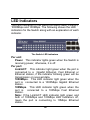
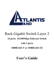
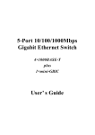
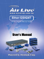
Ether-GSH24T 24-Port Gigabit Ethernet Switch User’s Manual FCC Warning This equipment has been tested and found to comply with the limits for a Class A digital device, pursuant to Part 15 of the FCC Rules. These limits are designed to provide reasonable protection against harmful interference when the equipment is operated in a commercial environment. This equipment generates, uses, and can radiate radio frequency energy and, if not installed and used in accordance with this user’s guide, may cause harmful interference to radio communications. Operation of this equipment in a residential area is likely to cause harmful interference in which case the user will be required to correct the interference at his own expense. CE Mark Warning This is a Class A product. In a domestic environment, this product may cause radio interference in which case the user may be required to take adequate measures. VCCI Warning This is a product of VCCI Class A Compliance. 2 UL Warning a) Elevated Operating Ambient Temperature-If installed in a closed or multi-unit rack assembly, the operating ambient temperature of the rack environment may be greater than room ambient. Therefore, consideration should be given to installing the equipment in an environment compatible with the manufacturer's maximum rated ambient temperature (Tmra). b) Reduced Air Flow- Installation of the equipment in a rack should be such that the amount of air flow required for safe operation of the equipment is not compromised. c) Mechanical Loading-Mounting of the equipment in the rack should be such that a hazardous condition is not achieved due to uneven mechanical loading. d) Circuit Overloading- Consideration should be given to the connection of the equipment to the supply circuit and the effect that overloading of circuits might have on over current protection and supply wiring. Appropriate consideration of equipment nameplate ratings should be used when addressing this concern. e) Reliable Earthing-Reliable earthing of rack-mounted equipment should be maintained. Particular attention should be given to supply connections other than direct connections to the branch circuit (e.g., use of power strips). 3 TABLE OF C ONTENTS ABOUT THIS GUIDE ...................................................... 5 TERMS ............................................................................ 5 OVERVIEW OF THIS USER’S GUIDE ................................... 5 INTRODUCTION ............................................................. 6 GIGABIT ETHERNET TECHNOLOGY ................................... 6 SWITCHING TECHNOLOGY................................................ 7 FEATURES ...................................................................... 8 UNPACKING AND SETUP ............................................. 9 UNPACKING .................................................................... 9 SETUP ............................................................................ 9 DESKTOP INSTALLATION ................................................ 10 RACK INSTALLATION ...................................................... 11 IDENTIFYING EXTERNAL COMPONENTS................. 12 FRONT PANEL ............................................................... 12 REAR PANEL ................................................................. 13 LED INDICATORS .......................................................... 14 TECHNICAL SPECIFICATIONS................................... 15 4 About This Guide This user’s guide tells you how to install your 24-Port 1000BASE-T Gigabit Ethernet Switch, how to connect it to your Gigabit Ethernet network. Terms For simplicity, this documentation uses the terms “Switch” (first letter upper case) to refer to the 24-Port 1000BASE-T Gigabit Ethernet Switch, and “switch” (first letter lower case) to refer to all Ethernet switches, including the 24-Port 1000BASE-T Gigabit Ethernet Switch. Overview of this User’s Guide Introduction. Describes the Switch and its features. Unpacking and Setup. Helps you get started with the basic installation of the Switch. Identifying External Components. Describes the front panel, rear panel, and LED indicators of the Switch. Technical Specifications. Lists the technical specifications of the Switch. 5 Introduction This section describes the features of the 24-Port 1000BASE-T Gigabit Ethernet Switch, as well as giving some background information about Gigabit Ethernet and switching technology. Gigabit Ethernet Technology Gigabit Ethernet is an extension of IEEE 802.3 Ethernet utilizing the same packet structure, format, and support for CSMA/CD protocol, full duplex, flow control, and management objects, but with a tenfold increase in theoretical throughput over 100-Mbps Fast Ethernet and a hundredfold increase over 10-Mbps Ethernet. Since it is compatible with all 10-Mbps and 100-Mbps Ethernet environments, Gigabit Ethernet provides a straightforward upgrade without wasting a company’s existing investment in hardware, software, and trained personnel. The increased speed and extra bandwidth offered by Gigabit Ethernet is essential to coping with the network bottlenecks that frequently develop as computers and their busses get faster and more users use applications that generate more traffic. Upgrading key components, such as your backbone and servers to Gigabit Ethernet can greatly improve network response times as well as significantly speed up the traffic between your subnets. 6 Gigabit Ethernet supports video conferencing, complex imaging, and similar data-intensive applications. Likewise, since data transfers occur 10 times faster than Fast Ethernet, servers outfitted with Gigabit Ethernet NIC’s are able to perform 10 times the number of operations in the same amount of time. Switching Technology Another key development pushing the limits of Ethernet technology is in the field of switching technology. A switch bridges Ethernet packets at the MAC address level of the Ethernet protocol transmitting among connected Ethernet or fast Ethernet LAN segments. Switching is a cost-effective way of increasing the total network capacity available to users on a local area network. A switch increases capacity and decreases network loading by making it possible for a local area network to be divided into different segments which don’t compete with each other for network transmission capacity, giving a decreased load on each. The switch acts as a high-speed selective bridge between the individual segments. Traffic that needs to go from one segment to another is automatically forwarded by the switch, without interfering with any other segments. This allows the total network capacity to be multiplied, while still maintaining the same network cabling and adapter cards. 7 Switching LAN technology is a marked improvement over the previous generation of network bridges, which were characterized by higher latencies. Routers have also been used to segment local area networks, but the cost of a router and the setup and maintenance required make routers relatively impractical. Today’s switches are an ideal solution to most kinds of local area network congestion problems. Features The 24-Port 1000BASE-T Gigabit Ethernet Switch was designed for easy installation and high performance in an environment where traffic on the network and the number of users increase continuously. 24 1000BASE-T Gigabit Ethernet ports Supports Auto-Negotiation for speed and duplex mode Supports Auto-MDIX for each port Full/half duplex transfer mode for 10Mbps and 100Mbps Full duplex transfer mode for 1000Mbps Wire speed reception and transmission Store-and-Forward switching method IEEE 802.3x flow control for full-duplex mode Integrated address Look-Up Engine, supports 32K absolute MAC addresses Supports 2M Bytes data buffer per device Extensive front-panel diagnostic LEDs 8 Unpacking and Setup This chapter provides unpacking and setup information for the Switch. Unpacking Open the shipping carton of the Switch and carefully unpack its contents. The carton should contain the following items: ♦ One 24-Port 1000BASE-T Gigabit Ethernet Switch ♦ Accessory pack: 2 mounting brackets and screws ♦ Four rubber feet with adhesive backing ♦ One AC power cord ♦ This User’s Guide If any item is found missing or damaged, please contact your local reseller for replacement. Setup The setup of the Switch can be performed using the following steps: ♦ The surface must support at least 5 kg. ♦ The power outlet should be within 1.82 meters (6 feet) of the device. 9 ♦ Visually inspect the power cord and see that it is secured fully to the AC power connector. ♦ Make sure that there is proper heat dissipation from and adequate ventilation around the Switch. Do not place heavy objects on the Switch. Desktop Installation When installing the Switch on a desktop or shelf, the rubber feet included with the device must be first attached. Attach these cushioning feet on the bottom at each corner of the device. Allow enough ventilation space between the device and the objects around it. Gigabit Ethernet Switch installed on Desktop 10 Rack Installation The Switch can be mounted in an EIA standard size, 19-inch rack, which can be placed in a wiring closet with other equipment. To install, attach the mounting brackets on the switch’s front panel (one on each side) and secure them with the screws provided. Attaching the mounting brackets to the Switch Then, use the screws provided with the equipment rack to mount the Switch in the rack. Installing the Switch in an equipment rack 11 Identifying External Components This chapter describes the front panel, rear panel and LED indicators of the Switch Front Panel The front panel of the Switch consists of 24 1000BASE-T Gigabit Ethernet ports and LED indicators. Front panel view of the Switch Sixteen Gigabit Ethernet ports of 10/100/1000Mbps Auto-Negotiation interface. Comprehensive LED indicators that display the conditions of the Switch and status of the network. A description of these LED indicators follows (see LED Indicators). 12 Rear Panel The rear panel of the Switch consists of an AC power connector. The following shows the rear panel of the Switch. Rear panel view of the Switch ♦ AC Power Connector This is a three-pronged connector that supports the power cord. Plug in the female connector of the provided power cord into this connector, and the male into a power outlet. Supported input voltages range from 100 - 240 VAC at 50/60 Hz. 13 LED Indicators The LED indicators of the Switch include Power, Link/Act, 1000Mbps and 100Mbps. The following shows the LED indicators for the Switch along with an explanation of each indicator. The Switch LED indicators Per unit: Power This indicator lights green when the Switch is receiving power, otherwise, it is off. Per port: Link/ACT. This indicator light green when the port is connected to a Gigabit Ethernet, Fast Ethernet or Ethernet station, if the indicator blinking green will be transmission or received data. 1000Mbps. This LED indicator light green when the port is connected to a 1000Mbps Gigabit Ethernet station. 100Mbps. This LED indicator light green when the port is connected to a 100Mbps Fast Ethernet station. Note: If the Link/ACT LED indicator light green and both of 1000Mbps and 100Mbps LED indicators off, mean the port is connecting to 10Mbps Ethernet station. 14 Technical Specifications General Standards: IEEE 802.3ab 1000BASE-T IEEE 802.3u 100BASE-TX IEEE 802.3 10BASE-T IEEE 802.3x Flow Control Protocol: CSMA/CD Data Transfer Rate: Ethernet: Fast Ethernet: 10Mbps (Half-duplex) 20Mbps (Full-duplex) 100Mbps (Half-duplex) 200Mbps (Full-duplex) Gigabit Ethernet: 2000Mbps (Full-duplex) Topology: Star Network Cables: Ethernet: 2-pair UTP Cat. 3,4,5, EIA/TIA-568 100-ohm screened twisted-pair (UTP) Fast Ethernet: 2-pair UTP Cat. 5, EIA/TIA-568 100-ohm screened twisted-pair (UTP) Gigabit Ethernet: 4-pair UTP Cat. 5, EIA/TIA-568 100-ohm screened twisted-pair (UTP) General Number of Ports: Twenty-four (24) 1000BASE-T Gigabit Ethernet ports Physical and Environmental AC inputs: 100 – 240 VAC Universal, 50/60 Hz Power Consumption: 55 watts maximum Operating Temperature: 0 ~ 40 degrees Celsius Storage Temperature: -10 ~ 70 degree Celsius Humidity: 5% ~ 90% RH, non-condensing Dimensions: 440 mm x 210 mm x 44 mm (1U), 19 inch rack-mount width EMI: FCC Class A, CE Marking Class A, VCCI Class A Safety: cUL(1950), CB(IEC60950) Performance Transmission Method: Store-and-forward RAM Buffer: 2MBytes per device Filtering Address Table: 32K MAC address per device MAC Address Learning: Self-learning, auto-aging 16