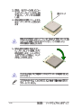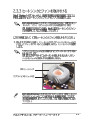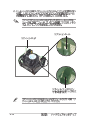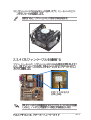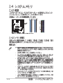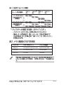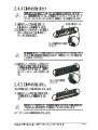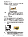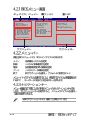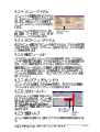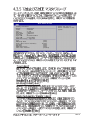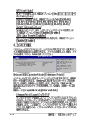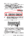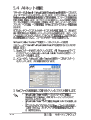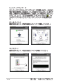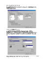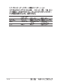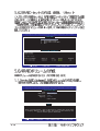
1
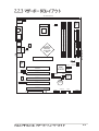
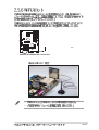
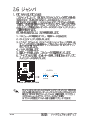
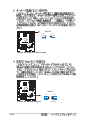
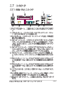
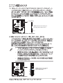
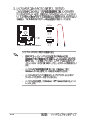
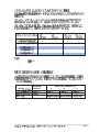
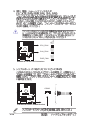
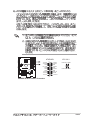
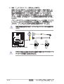
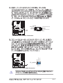
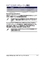
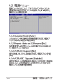
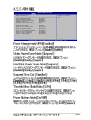
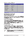
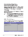
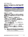
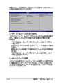
Motherboard
P4P800 SE
Checklist
Copyright© 2004 ASUSTeK COMPUTER INC. All Rights Reserved.
ii
iii
Features
Safeguards
iv
v
®
vi
This device complies with Part 15 of the FCC Rules. Operation is subject to
the following two conditions:
This equipment has been tested and found to comply with the limits for a
Class B digital device, pursuant to Part 15 of the FCC Rules. These limits
are designed to provide reasonable protection against harmful interference
in a residential installation. This equipment generates, uses and can radiate
radio frequency energy and, if not installed and used in accordance with
manufacturer’s instructions, may cause harmful interference to radio
communications. However, there is no guarantee that interference will not
occur in a particular installation. If this equipment does cause harmful
interference to radio or television reception, which can be determined by
turning the equipment off and on, the user is encouraged to try to correct the
interference by one or more of the following measures:
This digital apparatus does not exceed the Class B limits for radio noise
emissions from digital apparatus set out in the Radio Interference
Regulations of the Canadian Department of Communications.
This class B digital apparatus complies with Canadian ICES-003.
vii
viii
ix
x
®
®
®
®
®
®
®
®
®
®
®
1-1
®
®
®
®
®
1-2
1-3
®
1-4
1-5
1-6
®
P4P800 SE
SB_PWR1
ON
Standby
Power
OFF
Powered
Off
P4P800 SE Onboard LED
2-1
2-2
24.5cm (9.6in)
Accelerated Graphics Port (AGP1)
FLOPPY1
30.5cm (12.0in)
Top:Line In
Center:Line Out
Below:Mic In
SEC_IDE1
USB2.0 Top:
T: USB4 RJ-45 USBPW12
B: USB3
USBPW34
PRI_IDE1
Intel
82865PE
Memory
Controller
Hub
ATX12V1
DDR DIMM_B2 (64 bit,184-pin module)
USB20_12
DDR DIMM_B1 (64 bit,184-pin module)
COM1
DDR DIMM_A2 (64 bit,184-pin module)
DDR DIMM_A1 (64 bit,184-pin module)
PARALLEL PORT
SPDIF_O
CPU_FAN1
ATX Power Connector
Socket 478
Super
I/O
PS/2KBMS KBPWR
T: Mouse
B: Keyboard
Marvell
Gigabit
LAN
®
CHA_FAN1
SATA2
Intel
ICH5R
PCI1
CD1
AUX1
PCI2
MODEM1
USBPW56
USBPW78
PCI3
FP_AUDIO
USB_56
4Mbit
Firmware
Hub
USB_78
P4P800 SE
CR2032 3V
Lithium Cell
CMOS Power
PCI4
SPDIF_OUT
SATA1
SMB20
CLRTC1
Audio
Codec
PWR_FAN1
PCI5
SB_PWR1
GAME1
CHASSIS1
COM2
PANEL1
WIFI
2-3
2-4
2-5
®
®
®
®
®
2-6
®
90º~100º
2-7
®
2-8
®
®
®
®
®
®
®
2-9
2-10
2-11
80 Pins
DIMM_B2
DIMM_B1
DIMM_A2
DIMM_A1
P4P800 SE
P4P800 SE 184-Pin DDR DIMM Sockets
2-12
104 Pins
®
DIMM_A1
( )
(1)
(2)
(3)
(4)
(1)
(2)
DIMM_A2
( )
DIMM_B1
( )
DIMM_B2
( )
-
-
-
-
-
-
-
-
(3)*
CPU FSB
DDR DIMM
800 MHz
PC3200/PC2700*/PC2100
400/333*/266 MHz
533 MHz
PC2700/PC2100
333/266 MHz
400 MHz
PC2100
266 MHz
2-13
SS/DS
MDGA5F3G315B1EC2
ADATA
SS
ADD8608A8A-5B
•
•
256MB A DATA
MDOWB5F3G316B1EAE
Winbond
SS
W942508BH-5
•
•
256MB A DATA
MDOSS6F3G31JB1EAE
SAMSUNG
SS
K4H560838D-TCC4
•
•
256MB Apacer
77.10636.465
SAMSUNG
SS
K4H560838D-TCC4
•
•
512MB Apacer
77.10736.464
SAMSUNG
DS
K4H560838D-TCC4
•
•
•
256MB Corsair
CMX256-3500C2 XMS3502v1.1
N/A
SS
N/A •
•
512MB Corsair
CMX512-3500C2 XMS3502v1.1
N/A
DS
N/A •
•
256MB Hynix
HYMD232646B8J-D43AA
Hynix
SS
HY5DU56822BT-D43
•
•
•
512MB Hynix
HYMD232646B8J-D43AA
Hynix
DS
HY5DU56822BT-D43
•
•
•
128MB Infineon
HYS64D16301GU-5-B
Infineon
SS
HYB25D256160BT-5B •
•
•
256MB Infineon
HYS64D32300GU-5-B
Infineon
SS
HYB25D256800BT-5B •
•
•
512MB Infineon
HYS64D64320GU-5-B
Infineon
SS
HYB25D256800BT-5B •
•
•
256MB Kingston
KVR400X64C25/256
Winbond
SS
W942508BH-5
•
•
512MB Kingston
KVR400X64C25/512
Winbond
DS
W942508BH-5
•
256MB Kingston
KHX3500/256
N/A
SS
N/A
•
256MB MICRON
MT16VDDT3264AG-403B2
MICRON
DS
MT46V16M8-5TESB
•
•
512MB PSC
AL6D8A53TK1-5B
PSC
DS
A2S56D30ATP
•
•
•
SAMSUNG
SS
K4H560838E-TCCC
•
•
•
•
256MB SAMSUNG M368L3223ETM-CCC
2-14
A* B* C*
256MB A DATA
•
•
•
•
512MB SAMSUNG M368L6423ETM-CCC
SAMSUNG
DS
K4H560838E-TCCC
•
•
256MB Transcend TS32MLD64V4F3
SAMSUNG
SS
K4H560838D-TCC4
•
•
256MB Transcend TS32MLD64V4F3
Mosel
SS
V58C2256804SAT5
•
•
512MB Transcend TS64MLD64V4F3
SAMSUNG
DS
K4H560838D-TCC4
•
•
256MB Transcend TS64MLD64V4F3
Mosel
DS
V58C2256804SAT5
•
•
•
•
256MB TwinMOS
M2G9108AFATT9FD81AA4T TwinMOS
SS
TMD7608F8E50D
•
•
512MB TwinMOS
M2G9J16AGATT9F081AA4T TwinMOS
DS
TMD7608F8E50D
•
•
256MB TwinMOS
M2S9108AFAPS9F0811A-T
PSC
SS
A2S56D30ATP
•
•
•
256MB Winbond
W9425GCDB-5
Winbond
SS
W942508CH-5
•
•
•
512MB Winbond
W9451GCDB-5
Winbond
DS
W942508CH-5
•
•
•
2-15
2-16
IRQ
0
1
2
3*
4*
5*
6
7*
8
9*
10*
11*
12*
13
14*
15*
1
2
N/A
11
12
13
14
15
3
4
5
6
7
8
9
10
(COM2)
(COM1)
(LPT2
)
(LPT1)
CMOS/
ACPI
PCI
PCI
PS/2
1
2
IRQ
IRQ
IDE
IDE
A
B
C
D
E
F
G
H
—
—
PCI
1
—
—
—
—
—
PCI
2
—
—
—
—
—
—
PCI
3
—
—
—
—
—
—
—
PCI
4
—
—
—
—
—
—
—
PCI
5
—
—
—
—
—
—
—
—
—
—
—
—
—
—
—
—
—
—
—
—
—
—
—
—
—
—
—
—
—
AGP
LAN
—
—
—
—
2-17
®
P4P800 SE
Keyed for 1.5v
P4P800 SE Accelerated Graphics Port (AGP)
2-18
™
®
WIFI
P4P800 SE
P4P800 SE WIRELESS Connectors
™
™
2-19
CLRTC1
®
1 2
P4P800 SE
P4P800 SE Clear RTC RAM
2-20
Normal
(Default)
2 3
Clear CMOS
USBPW12
USBPW34
2 3
1 2
+5V
(Default)
+5VSB
®
USBPW56
USBPW78
1 2
2 3
P4P800 SE
P4P800 SE USB Device Wake Up
+5V
(Default)
+5VSB
2-21
KBPWR
1 2
2 3
+5V
(Default)
+5VSB
®
P4P800 SE
P4P800 SE Keyboard Power Setting
SMB20
®
1 2
2 3
P4P800 SE
Enable
P4P800 SE SMB2.0 Support
2-22
Disable
(Default)
1
2
3
4
5
6
11
10
9
8
7
2-23
2-24
FLOPPY1
NOTE: Orient the red markings on
the floppy ribbon cable to PIN 1.
®
P4P800 SE
PIN 1
SEC_IDE1
P4P800 SE Floppy Disk Drive Connector
P4P800 SE
P4P800 SE IDE Connectors
PRI_IDE1
®
NOTE: Orient the red markings
(usually zigzag) on the IDE
ribbon cable to PIN 1.
PIN 1
2-25
P4P800 SE SATA Connectors
®
2-26
GND
RSATA_TXP1
RSATA_TXN1
GND
RSATA_RXP1
RSATA_RXN1
GND
GND
RSATA_TXP2
RSATA_TXN2
GND
RSATA_RXP2
RSATA_RXN2
GND
SATA2
®
SATA1
P4P800 SE
®
®
®
®
®
P-ATA
2
1
(2
)
S-ATA
0
(2
)
(1
)
1
(1
)
—
—
—
—
:
—
BIOS
Windows®
2000/XP
A
Windows® 98/ME/NT4.0
B
C
2-27
GND
+12V
Rotation
GND
+12V
Rotation
CPU_FAN1
CHA_FAN1
GND
+12V
Rotation
®
P4P800 SE
PWR_FAN1
P4P800 SE 12-Volt Fan Connectors
COM2
®
PIN 1
P4P800 SE
P4P800 SE Serial COM2 Bracket
2-28
ATXPWR1
®
P4P800 SE
+3.3VDC
-12.0VDC
COM
PS_ON#
COM
COM
COM
-5.0VDC
+5.0VDC
+5.0VDC
+3.3VDC
+3.3VDC
COM
+5.0VDC
COM
+5.0VDC
COM
PWR_OK
+5VSB
+12.0VDC
ATX12V1
+12V DC GND
+12V DC GND
P4P800 SE ATX Power Connector
2-29
USB56
P4P800 SE USB 2.0 Header
2-30
1
USB+5V
USB_P5USB_P5+
GND
USB78
1
USB+5V
USB_P7USB_P7+
GND
USB+5V
USB_P8USB_P8+
GND
NC
USB+5V
USB_P6USB_P6+
GND
NC
®
P4P800 SE
MODEM
®
Modem-Out
Ground
Ground
Modem-In
Right Audio Channel
Ground
Ground
Left Audio Channel
CD1(Black) AUX1(White)
P4P800 SE
®
BLINE_OUT_L
AGND
+5VA
BLINE_OUT_R
P4P800 SE Internal Audio Connectors
MIC2
MICPWR
Line out_R
NC
Line out_L
FP_AUDIO
P4P800 SE
P4P800 SE Front Panel Audio Connector
2-31
+5V
J1B2
J1CY
GND
GND
J1CX
J1B1
+5V
®
P4P800 SE
MIDI_IN
J2B2
J2CY
MIDI_OUT
J2CX
J2B1
+5V
GAME1
P4P800 SE Game Connector
Chassis Signal
GND
®
+5VSB_MB
CHASSIS1
P4P800 SE
(Default)
P4P800 SE Chassis Alarm Lead
2-32
P4P800 SE
SMI Lead
+5V
Ground
Ground
Speaker
PLED-
IDE_LED
Reset
Ground
®
ExtSMI#
Ground
PWR
Ground
IDE_LED+
IDE_LED-
PLED+
Power LED
Speaker
Connector
Reset SW
ATX Power
Switch*
* Requires an ATX power supply.
P4P800 SE System Panel Connectors
2-33
2-34
3-1
3-2
®
format A:/S
®
®
®
4-1
A:\>afudos /iP4P800SE.rom
AMI Firmware Update Utility - Version 1.10
Copyright (C) 2002 American Megatrends, Inc. All rights reserved.
Reading file ..... done
Erasing flash .... done
Writing flash .... 0x0008CC00 (9%)
4-2
A:\>afudos /iP4P800SE.rom
AMI Firmware Update Utility - Version 1.10
Copyright (C) 2002 American Megatrends, Inc. All rights reserved.
Reading file ..... done
Erasing flash .... done
Writing flash .... 0x0008CC00 (9%)
Verifying flash .. done
A:\>
”
”
A:\>afudos /oMYBIOS03.rom
AMI Firmware Update Utility - Version 1.10
Copyright (C) 2002 American Megatrends, Inc. All rights reserved.
Reading flash ..... 0x0008CC00 (9%)
4-3
3.
BIOS
600 KB
A:\>afudos /oMYBIOS03.rom
AMI Firmware Update Utility - Version 1.10
Copyright (C) 2002 American Megatrends, Inc. All rights reserved.
Reading flash ..... done
A:\>
User recovery requested. Starting BIOS recovery...
Checking for floppy...
4-4
User recovery requested. Starting BIOS recovery...
Checking for floppy...
Floppy found!
Reading file “P4P800SE.rom”. Completed.
Start flashing...
Flashed successfully. Rebooting.
Bad BIOS checksum. Starting BIOS recovery...
Checking for floppy...
4-5
Bad BIOS checksum. Starting BIOS recovery...
Checking for floppy...
Floppy found!
Reading file “P4P800SE.ROM”. Completed.
Start flashing...
Bad BIOS checksum. Starting BIOS recovery...
Checking for floppy...
Bad BIOS checksum. Starting BIOS recovery...
Checking for floppy...
Floppy not found!
Checking for CD-ROM...
CD-ROM found.
Reading file “P4P800SE.ROM”. Completed.
Start flashing...
4-6
®
4-7
4-8
4-9
System
System
Legacy
Legacy
Time
Date
Diskette A
Diskette B
Primary IDE Master
Primary IDE Slave
Secondary IDE Master
Secondary IDE Slave
Third IDE Master
Fourth IDE Master
IDE Configuration
System Information
4-10
[22:16:45]
[Tue 01/15/2002]
[1.44M, 3.5 in.]
[Disabled]
[ST321122A]
[Not Detected]
[Not Detected]
[Pioneer CD-ROM ATA]
[Not Detected]
[Not Detected]
Use [ENTER], [TAB] or
[SHIFT-TAB] to
select a field.
Use [+] or [-] to
configure system time.
4-11
System
System
Legacy
Legacy
Time
Date
Diskette A
Diskette B
Primary IDE Master
Primary IDE Slave
Secondary IDE Master
Secondary IDE Slave
Third IDE Master
Fourth IDE Master
IDE Configuration
System Information
4-12
[22:16:45]
[Tue 01/15/2002]
[1.44M, 3.5 in.]
[Disabled]
[ST321122A]
[Not Detected]
[Not Detected]
[Pioneer CD-ROM ATA]
[Not Detected]
[Not Detected]
Use [ENTER], [TAB] or
[SHIFT-TAB] to
select a field.
Use [+] or [-] to
configure system time.
Primary IDE Master
Select the type of
device connected to the
system.
Device
: Hard Disk
Vendor
: ST32122A
Size
: 2.1GB
LBA Mode
: Supported
Block Mode
: 16Sectors
PIO Mode
: 4
Async DMA
: MultiWord DMA-2
Ultra DMA
: Ultra DMA-2
SMART Monitoring: Supported
Type
LBA/Large Mode
Block (Multi-sector Transfer)
PIO Mode
DMA Mode
SMART Monitoring
32Bit Data Transfer
[Auto]
[Auto]
M [Auto]
[Auto]
[Auto]
[Auto]
[Disable]
4-13
IDE Configuration
Onboard PCI IDE Operate Mode
Enhanced Mode Support On
Configure S-ATA as RAID
IDE Detect Time Out (Sec)
4-14
[Enhanced Mode]
[S-ATA]
[No]
[35]
Set [Compatible Mode]
when Legacy OS (i.e.
WIN ME, 98, NT4.0, MS
DOS) is used.
Set [Enhanced Mode]
when Native OS (i.e.
Win2000, WIN XP) is
used.
4-15
AMI BIOS
Version
: 1001.004
Build Date : 01/27/04
Processor
Type
Speed
Count
: Intel(R) Pentium(R) 4 Family CPU 2.40G
: 2400MHz
: 1
System Memory
Size
: 128MB
JumperFree Configuration
CPU Configuration
Chipset
Onboard Devices Configuration
PCIPnP
USB Configuration
Speech Configuration
Instant Music Configuration
4-16
Adjust system
frequency/voltage.
Configure System Frequency/Voltage
AI Overclock Tuner
[Standard]
Performance Mode
[Auto]
Select the target CPU
frequency, and the
relevant parameters will
be auto-adjusted.
Frequencies higher than
CPU manufacturer
recommends are not
guaranteed to be stable.
If the system becomes
unstable, return to the
default.
4-17
Configure System Frequency/Voltage
AI Overclock Tuner
CPU External Frequency (MHz)
DRAM Frequency
AGP/PCI Frequency (MHz)
[Manual]
[133]
[Auto]
[Auto]
CPU VCore Voltage
DDR Reference Voltage
AGP VDDQ Voltage
[Auto]
[Auto]
[1.50V]
Performance Mode
[Auto]
Select the target CPU
frequency, and the
relevant parameters
will be auto-adjusted.
Frequencies higher
than CPU manufacturer
recommends are not
guaranteed to be stable.
If the system becomes
unstable, return to the
default.
(value is auto-detected)
4-18
Configure advanced CPU settings
Manufacturer
Brand String
Frequency
FSB Speed
: Intel(R)
: Intel(R) Pentium(R) 4 Family CPU 2.4G
: 2400MHz
: 533MHz
Cache L1
Cache L2
Cache L3
: 8 KB
: 512 KB
: 0 KB
Ratio Status : Locked
Ratio Actual Value : 18
VID CMOS Setting:
Maximum Value Limit
CPU Internal Thermal Control
Selects the VID
setting at which
the processor is
to run.
[ 62]
[Disabled]
[Auto]
4-19
Advanced Chipset settings
WARNING: Setting wrong values in the sections below
may cause system to malfunction.
4-20
Configure DRAM Timing by SPD
Memory Acceleration Mode
DRAM Idle Timer
DRAM Refresh Rate
[Enabled]
[Auto]
[Auto]
[Auto]
Graphic Adapter Priority
Graphics Aperture Size
Spread Spectrum
[AGP/PCI]
[ 64MB]
[Enabled]
ICH Delayed Transaction
[Enabled]
MPS Revision
[1.4]
Set DRAM timing
parameters according
to DRAM SPD
or manually.
4-21
OnBoard AC’97 Audio
OnBoard LAN
OnBoard LAN Boot ROM
[Auto]
[Enabled]
[Disabled]
Serial Port1 Address
Serial Port2 Address
Parallel Port Address
Parallel Port Mode
ECP Mode DMA Channel
Parallel Port IRQ
OnBoard Game/MIDI Port
[3F8/IRQ4]
[2F8/IRQ3]
[378]
[ECP]
[DMA3]
[IRQ7]
[Disabled]
’
®
4-22
®
4-23
Advanced PCI/PnP settings
WARNING: Setting wrong values in the sections below
may cause system to malfunction.
4-24
Plug and Play OS
PCI Latency Timer
Allocate IRQ to PCI VGA
Palette Snooping
PCI IDE BusMaster
[No]
[64]
[Yes]
[Disabled]
[Enabled]
IRQ3
IRQ4
IRQ5
IRQ7
IRQ9
IRQ10
IRQ11
IRQ14
IRQ15
[Available]
[Available]
[Available]
[Available]
[Available]
[Available]
[Available]
[Available]
[Available]
PCI
PCI
PCI
PCI
[Auto]
[Auto]
[Auto]
[Auto]
Slot-1/5 IRQ Preference
Slot-2 IRQ Preference
Slot-3 IRQ Preference
Slot-4 IRQ Preference
NO: Lets the BIOS
configure all the
devices in the system.
YES: Lets the
operating system
configure Plug and
Play (PnP) devices not
required for boot if
your system has a Plug
and Play operating
system.
USB Configuration
Module Version
Enables USB host
controllers.
- 2.23.0-4.3
USB Devices Enabled :
None
USB Function
Legacy USB Support
USB 2.0 Controller
USB 2.0 Controller Mode
[8 USB Ports]
[Auto]
[Enabled]
[HiSpeed]
USB Mass Storage Device Configuration
4-25
USB Mass Storage Device Configuration
USB Mass Storage Reset Delay
[20 Sec]
No USB Mass Storage device detected
4-26
Number of seconds
POST waits for the USB
mass storage device
after the start unit
command.
Instant Music Option
Instant Music
[Disabled]
If enabled, power up
by PS/2 kepyboard
function will be
disabled.
4-27
Suspend Mode
Repost Video on S3 Resume
ACPI 2.0 Support
ACPI APIC Support
APM Configuration
Hardware Monitor
4-28
[Auto]
[No]
[No]
[Enabled]
Select the ACPI state
used for System
Suspend.
Enable or disable
APM.
APM Configuration
Power Management/APM
Video Power Down Mode
Hard Disk Power Down Mode
Suspend Time Out
Throttle Slow Clock Ratio
[Enabled]
[Suspend]
[Suspend]
[Disabled]
[50%]
Power Button Mode
Restore on AC Power Loss
[On/Off]
[Power Off]
Power
Power
Power
Power
Power
[Disabled]
[Disabled]
[Disabled]
[Disabled]
[Disabled]
On
On
On
On
On
By RTC Alarm
By External Modems
By PCI Devices
PS/2 Keyboard
PS/2 Mouse
4-29
4-30
CPU Temperature
Hardware Monitor
CPU Temperature
MB Temperature
Power Temperature
[31.5° C/86.5° F]
[31° C/87.5° F]
[N/A]
Q-Fan Control
[Disabled]
CPU Fan Speed
Chassis Fan Speed
Power Fan Speed
[5232RPM]
[N/A]
[N/A]
VCORE Voltage
3.3V Voltage
5V Voltage
12V Voltage
[1.552V]
[3.408V]
[5.080V]
[11.977V]
4-31
Boot Settings
Boot Device Priority
Boot Settings Configuration
Security
4-32
Specifies the Boot
Device Priority
sequence.
Boot Device Priority
1st
2nd
3rd
4th
Boot
Boot
Boot
Boot
Device
Device
Device
Device
[1st Floppy Drive]
[PM-ST32122A]
[SS-Pioneer CD-ROM]
[Yukon PXE]
Boot Settings Configuration
Quick Boot
Full Screen Logo
Add On ROM Display Mode
Bootup Num-Lock
PS/2 Mouse Support
Boot to OS/2
Wait for ‘F1’ If Error
Hit ‘DEL’ Message Display
Interrupt 19 Capture
[Enabled]
[Enabled]
[Force BIOS]
[On]
[Auto]
[No]
[Enabled]
[Enabled]
[Disabled]
Specifies the boot
sequence from the
available devices.
A device enclosed in
parenthesis has been
disabled in the
corresponding type
menu.
Allows BIOS to skip
certain tests while
booting. This will
decrease the time
needed to boot the
system.
4-33
‘
‘
4-34
’
’
Security Settings
Supervisor Password
User Password
:Not Installed
:Not Installed
<Enter> to change
password.
<Enter> again to disable
password.
Change Supervisor Password
Boot Sector Virus Protection
[Disabled]
4-35
Security Settings
Supervisor Password
User Password
4-36
Installed
Not Installed
Change Supervisor Password
User Access Level
Change User Password
Clear User Password
Password Check
[Setup]
Boot Sector Virus Protection
[Disabled]
[Full Access]
<Enter> to change
password.
<Enter> again to disable
password.
Exit Options
Exit & Save Changes
Exit & Discard Changes
Discard Changes
Exit system setup after
saving the changes.
F10 key can be used for
this operation.
Load Setup Defaults
4-37
4-38
®
®
5-1
®
®
®
5-2
®
5-3
5-4
5-5
5-6
5-7
5-8
5-9
CD
ON/OFF
PLAY/PAUSE
Esc
F1
STOP/EJECT
F2
PREVIOUS
NEXT
F3
F4
VOL. DOWN
VOL. UP
F5
F6
CAPS
LOCK
LED
CD ON/OFF
PLAY/PAUSE
STOP/EJECT
PREVIOUS
VOL. DOWN
5-10
F7
NEXT
VOL. UP
SCROLL
LOCK
LED
F8
5-11
®
®
®
®
5-12
®
5-13
5-14
5-15
5-16
®
®
®
®
®
®
®
®
\
\
5-17
®
Copyright(C) 2003 Intel Corporation. All Rights Reserved. v3.x.x.xxxx
[ MAIN MENU ]
1.
2.
3.
4.
Create RAID Volume
Delete RAID Volume
Reset Disks to Non-RAID
Exit
[ DISK/VOLUME INFORMATION ]
RAID Volumes:
None defined.
Non-RAID Disks:
Port Drive Model
0 ST380013AS
1 ST380013AS
[
Serial #
xxxxxxxx
xxxxxxxx
]-Select
Size
74.5GB
74.5GB
[ESC] Exit
Status
Normal
Normal
Bootable
Yes
Yes
[Enter]-Select Menu
Copyright(C) 2003 Intel Corporation. All Rights Reserved. v3.x.x.xxxx
[ CREATE ARRAY MENU ]
Name:
RAID Level:
Strip Size:
Capacity:
RAID_Volume1
RAID0(Stripe)
128KB
149.0GB
Create Volume
[ HELP ]
Enter a string between 1 and 16 characters in length taht can be used
to uniquely identify the RAID volume. This name is case sensitive and
can not contain special characters.
[
5-18
]-Change
[TAB]-Next
[ESC] Previous Menu
[Enter]-Select
Are you sure you want to create this volume (Y/N)
Copyright(C) 2003 Intel Corporation. All Rights Reserved. v3.x.x.xxxx
[ DELETE ARRAY MENU ]
Name
RAID_Volume1
Level
Drives
RAID0(Stripe) 2
Capacity Status
149.0GB Normal
Bootable
Yes
[ HELP ]
Deleting a volume will destroy the volume data on the drive(s) and
cause any member disks to become available as non-RAID disks.
WARNING: EXISTING DATA WITHING THIS VOLUME WILL BE LOST AND NON-RECOVERABLE
[
]-Change
[TAB]-Next
[<ESC>]-Previous Menu
[<DEL>]-Delete Volume
5-19
[ VOLUME DELETE VERIFICATION ]
Are you sure you want to delete this volume?
ALL DATA IN THE VOLUME WILL BE LOST!!
Are you sure you want to delete volume "RAID_Volume1"? (Y/N)
Copyright(C) 2003 Intel Corporation. All Rights Reserved. v3.x.x.xxxx
[ MAIN MENU ]
1.
2.
3.
4.
Create RAID Volume
Delete RAID Volume
Reset Disks to Non-RaID
Exit
[ DISK/VOLUME INFORMATION ]
RAID Volumes:
None defined.
Non-RAID Disks:
Port Drive Model
0 ST380013AS
1 ST380013AS
[
Serial #
xxxxxxxx
xxxxxxxx
]-Select
[ESC] Exit
Size
74.5GB
74.5GB
Status
Normal
Normal
Bootable
Yes
Yes
[Enter]-Select Menu
[ RESET ALL DATA RAID DATA ]
Resetting all RAID data will remove any internal RAID structures
from all RAID disks, including disks with working volumes. These
structures are used to maintain the RAID volumes. By removing
these structures, the drive will revert back to a Non-RAID disk
that can then be used or reallocated to a new RAID volume.
WARNING: Selecting "Yes" will cause all data on any RAID disk
(RAID Volume or Other RAID Disk) to be lost.
Are you sure you want to destroy all RAID data (Y/N):
5-20
®
5-21
5-22