1
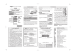
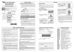
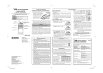
VX-351PMR446
(VX-351-EG3J-1)
OPERATING MANUAL
CONTENTS
Important Notice .............................................................................................................................................................. 1
Important Notice for the Li-ion Battery Pack ............................................................................................................... 2
Disposal of Your Electronic and Electric Equipment .................................................................................................... 2
Attention in Case of Use .................................................................................................................................................. 3
Controls & Connectors .................................................................................................................................................... 3
Before You Begin .............................................................................................................................................................. 4
Battery Pack Installation and Removal ........................................................................................................................ 4
Battery Charge ............................................................................................................................................................. 4
Low Battery Indication ................................................................................................................................................ 5
Operation .......................................................................................................................................................................... 6
Programmable Key Functions ........................................................................................................................................ 8
Monitor ........................................................................................................................................................................ 8
SQL Off ....................................................................................................................................................................... 8
Scan ............................................................................................................................................................................. 8
Follow-Me Scan ........................................................................................................................................................... 9
Encryption .................................................................................................................................................................... 9
Advanced Feature .......................................................................................................................................................... 10
Dual Scan ................................................................................................................................................................... 10
Priority Check ............................................................................................................................................................ 10
Time-Out Timer (TOT) .............................................................................................................................................. 10
Busy Channel Lock-Out (BCLO) .............................................................................................................................. 10
ARTS (Auto Range Transpond System) .................................................................................................................... 10
Power Save ................................................................................................................................................................ 10
Supplied Accessories ....................................................................................................................................................... 11
Optional Accessories ....................................................................................................................................................... 11
Sub-Audio Set Mode (Programming the CTCSS Tone Frequency / DCS Code ....................................................... 12
IMPORTANT NOTICE
H Please read this manual carefully to become familiar with the features of this transceiver.
H When transmitting, hold the radio in a vertical position with its microphone 2.5 to 5 cm away from your
mouth and keep the antenna at least 2.5cm away from your head.
H The radio must be used with a maximum operating duty cycle not exceeding 50 %, in typical Push-to-Talk
(PTT) configurations. DO NOT transmit for more than 50 % of total radio use time (50 % duty cycle).
Transmitting more than 50 % of the time can cause RF exposure compliance requirements to be exceeded.
The radio is transmitting when the red LED on the top of the radio is illuminated. You can cause the radio
to transmit by pressing the PTT button or by using the VOX headset, model VC-25.
H Always use the FNB-V95LI or FNB-V96LI Lithium-Ion Battery.
H Perform the battery charging where the ambient temperature range +10 °C to +40 °C. Charge out of this
range could cause damage to the battery pack.
H Battery Pack shall not be exposed to excessive heat such as sunshine, fire or the like.
H Always use Vertex Standard authorized accessories.
Vertex Standard shall not be liable for any damage or accidents such as fire, leakage or explosion of
batteries, etc., caused by the malfunction of non-Vertex Standard accessories.
H This radio generates RF electromagnetic energy during transmit mode. This radio is designed for and
classified as occupational use only, meaning it must be used only during the course of employment by
individuals aware of hazardous, and the ways to minimize such hazardous. This radio is not intended for
use by the General Population in an uncontrolled environment.
Page 1
IMPORTANT NOTICE FOR THE LI-ION BATTERY PACK
CONTAINS LITHIUM-ION BATTERY.
MUST BE RECYCLED OR DISPOSED OF PROPERLY.
H Never short-circuit the connection terminals on the battery or charger!
Li-ion
H Do not attempt to open the battery pack, as personal injury or damage to the battery pack could
occur if a cell or cells become accidentally short-circuited.
H Before using a battery pack for the first time, charge it completely. Do not attempt charge a pack with the incorrect
charger, as this can damage or shorten the life of the pack.
H When a battery pack is not used for a long time, please remove it from the transceiver. Also, while in storage, the
charge will drain slightly over time and the battery should be recharged 50% each six months.
H When carefully maintained, a pack should be useful for about 300 charge/discharge cycles.
H The following abuses can shorten the useful life of the battery,and should be avoided:
Exceeding the specified temper-ature limits;
Overcharging with an incorrect charger, or charging for too long;
Shorting the terminals, or using the pack with equipment not designed for it;
Reversing charge polarity. Use only the proper charger. If this is tampered with or another charger is used,
permanent damage may result;
Submersing the battery in water, or attempting to open the battery casing.
H After storage, the battery should be returned to room temperature before use. It may first function at reduced
capacity, but should return to full capacity after several complete charge/discharge cycles.
H Replace the pack if charge life becomes very short.
DISPOSAL OF YOUR ELECTRONIC AND ELECTRIC EQUIPMENT
Products with the symbol (crossed-out wheeled bin) cannot be disposed as household waste. Electronic and
Electric Equipment should be recycled at a facility capable of handling these items and their waste byproducts.
In EU countries, please contact your local equipment supplier representative or service center for information about the waste collection system in your country.
Page 2
Attention in Case of Use
This transceiver works on frequencies which are not
generally permitted.
For frequency allocation, apply for a licence at your
local spectrum management authority.
For actual usage contact your dealer or sales shop
in order to get your transceiver adjusted to the allocated frequency range.
AUT
DNK
GRC
LVA
SVK
NOR
List of the practicable area
BEL
BGR
CYP
CZE
ESP
EST
FIN
FRA
HUN
IRL
ITA
LTU
MLT
NLD
POL
PRT
SVN SWE CHE
ISL
CONTROLS & CONNECTORS
LED Indicator
Glows Green
Blinking Green
Glows Red
Blinking Red
Glows Yellow
SCAN or FM-SCAN is activated (or Monitor on)
Busy Channel (or SQL off)
Transmitting
Battery Voltage is Low
Sub-Audio Set Mode
CH (Channel) Selector
Antenna
DEU
GBR
LUX
ROU
LIE
VOL/PWR Knob
Speaker
Push To Talk
(PTT) Switch
MIC/SP Jack
[SIDE 1] Key
OPERATING TEMPERATURE RANGE
Operation: –25 °C to +55 °C
Battery Charging: +10 °C to +40 °C
Microphone
[SIDE 2] Key
Battery Pack Latch
Page 3
BEFORE YOU BEGIN
BATTERY PACK INSTALLATION AND REMOVAL
BATTERY CHARGE
To install the battery, hold the transceiver with your
left hand, so your palm is over the speaker and your
thumb is on the top of the belt clip. Insert the battery
pack into the battery compartment on the back of the
radio while tilting the Belt Clip outward, then push
the bottom side of the battery pack until the battery
pack locks with the Battery Pack Latch.
1. Insert the DC plug from the PA-42
AC Adapter into the DC jack on the
bottom side of the CD-34 Desktop
Rapid Charger, then plug the PA-42
AC Adapter into the AC line outlet.
2. Turn the transceiver “off”, then insert
the transceiver into the CD-34 Desktop Rapid Charger while aligning the slots of the battery pack with the guides in the nest of the CD-34;
refer to the illustration below for details on proper positioning of the battery pack.
3. If the transceiver is inserted correctly, the LED indicator will glow red. A fully-discharged pack will be
charged completely in approximately 2 hours.
4. The LED indicator will change to green when charging is nearing completion. The
battery pack becomes fully
charged approximately 30 minutes later.
5. When charging is completed, remove the transceiver from the CD-34
Align the slots of the battery
Desktop Rapid Charger, pack with the guides in the
and unplug the PA-42 AC nest of the CD-34 Desktop
Adapter from the AC line Rapid Charger.
outlet.
Push the bottom side
of the battery pack
p
Belt Cli
Tilt the
Insert
ack
ttery P
the Ba
To remove the battery, turn the radio off and remove
any protective cases. Slide the Battery Pack Latch on
the bottom of the radio, then slide the battery downward and out from the radio while holding the Belt
Clip.
Page 4
BEFORE YOU BEGIN
Important Notes!
Do not connect an improper AC Adapter to the CD34 Desktop Rapid Charger. Use only the supplied PA42 AC Adapter.
Disconnect the transceiver from the CD-34 Desktop
Rapid Charger, and unplug the PA-42 AC Adapter
from the AC line outlet, when charging is completed.
The PA-42 AC Adapter and/or CD-34 Desktop Rapid
Charger will generate a moderate amount of heat during the charging process. This is a normal condition.
The PA-42 AC Adapter and CD-34 Desktop Rapid
Charger is designed for charging only, and is not designed for operation (transmission/reception) of the
transceiver.
Periodically wipe the charging terminals in the nest of
the CD-34 Desktop Rapid Charger, using a dry cloth,
to ensure good connections between the charger and
battery.
Caution!
Do not attempt to open any of the rechargeable
Lithium-Ion packs, as they could explode if accidentally short-circuited.
LOW BATTERY INDICATION
As the battery discharges during use, the voltage gradually becomes lower. When the battery voltage becomes to
low, substitute a freshly charged battery and recharge the
depleted pack. When the battery voltage becomes to low,
the LED indicator on the top of the radio will blink red
and an alert beeper will sound.
Caution!!
When charging a battery pack alone (not attached to
the transceiver), do not allow any metal object to short
the terminals on the battery pack.
Do not allow any metal objects to short the terminals
in the nest of the CD-34 Desktop Rapid Charger, as a
short-circuit could cause overheating of the charger
circuitry.
Page 5
English
OPERATION
OPERATION QUICK START
Turn the top panel’s VOL/
PWR knob clockwise to
turn on the radio on.
Turn the top panel’s CH selector knob to choose the
desired operating channel.
Rotate the VOL/PWR
knob to set the volume
level. If no signal is
present, press and hold in
the [SIDE 1] key (default:
[MONI/SQL OFF ] key)
for more than one second;
background noise will now be heard, and you may
use this to set the VOL/PWR knob for the desired
audio level.
Page 6
Press and hold in the
[SIDE 1 ] key (default:
[MONI/SQL OFF ] key)
for more than one second
(or press the key twice) to
quiet the noise and resume
normal (quiet) monitoring.
To transmit, monitor the channel and make sure it is
clear.
To transmit, press and hold
in the PTT switch. Speak
into the microphone area of
the front panel grille (lower
right-hand corner) in a normal voice level. To return
to the Receive mode, release the PTT switch.
Press the [SIDE 2 ] key
(default: [SCAN] key) to
start scanning. If and when
the scanner encounters a
signal strong enough to
open the squelch, the scanner will remain halted for
as long as there is carrier present on the channel. After
the carrier drops at the end of the other station’s transmission, scanning will resume.
OPERATION
If a Speaker/Microphone is available, remove the plastic cap and its two mounting screws from the right side
of the transceiver, then insert the plug from the Speaker/
Microphone into the MIC/SP jack; secure the plug using the screws supplied with the Speaker/Microphone.
Hold the speaker grille up next to your ear while receiving. To transmit, press the PTT switch on the
Speaker/Microphone, just as you would on the main
transceiver’s body.
Note: Save the original plastic cap and its mounting
screws. They should be re-installed when not
using the Speaker/Microphone.
VX-351PMR446 DEFAULT SETTING
CHANNEL
1
2
3
4
5
6
7
8
9
10
11
12
13
14
15
16
FREQUENCY NO. (FREQUENCY)
1 ch (446.00625 MHz)
2 ch (446.01875 MHz)
3 ch (446.03125 MHz)
4 ch (446.04375 MHz)
5 ch (446.05625 MHz)
6 ch (446.06875 MHz)
7 ch (446.08125 MHz)
8 ch (446.09375 MHz)
1 ch (446.00625 MHz)
2 ch (446.01875 MHz)
3 ch (446.03125 MHz)
4 ch (446.04375 MHz)
5 ch (446.05625 MHz)
6 ch (446.06875 MHz)
7 ch (446.08125 MHz)
8 ch (446.09375 MHz)
CTCSS/DCS (TONE NO.)
DCS 114 (76)
DSC 115 (77)
DCS 023 (60)
DCS 025 (61)
DCS 026 (62)
DCS 071 (72)
DCS 072 (73)
DCS 073 (74)
DCS 152 (86)
DCS 155 (87)
DCS 156 (88)
DCS 162 (89)
DCS 165 (90)
DCS 205 (93)
DCS 212 (94)
DCS 223 (95)
Page 7
PROGRAMMABLE KEY FUNCTIONS
The VX-351PMR446 provide [SIDE 1] and [SIDE 2]
keys. These “Programmable” keys functions can be customized (set to other functions) via the CE95 Programming Software. The possible Programmable key features
are illustrated below, and their functions are explained
below. For further details, contact your Vertex Standard
dealer.
For future reference, check the box at the right to each
function that has been assigned to the Programmable key
on your particular radio, and keep it handy.
FUNCTION
Monitor
SQL Off
Scan
Follow-Me Scan
Encryption
PROGRAMMABLE KEY
(PRESS / PRESS AND HOLD)
[SIDE 1] KEY
[SIDE 2] KEY
/
/
/
/
/
/
/
/
/
/
PROGRAMMABLE KEY DEFAULT SETTING
[SIDE 1]
[SIDE 2]
PRESS KEY
Monitor
Scan
PRESS & HOLD KEY
SQL Off
—
Page 8
MONITOR
Press (or Press and hold) the assigned Programmable key
to disable the CTCSS- and DCS-controlled squelch; the LED
indicator on the top of the transceiver will glow green.
SQL OFF
Press (or Press and hold) the assigned Programmable key
to hear background noise (unmute the transceiver); the LED
indicator on the top of the transceiver will blink green.
SCAN
The Scanning feature is used to monitor multiple channels programmed into the transceiver. While scanning, the
transceiver will check each channel for the presence of a
signal, and will stop on a channel if a signal is present.
To activate scanning:
Press (or Press and hold) the assigned Programmable key.
The scanner will search the channels, looking for active ones; it will pause each time it finds a channel on
which someone is speaking.
To stop scanning:
Press (or Press and hold) the assigned Programmable key again.
PROGRAMMABLE KEY FUNCTIONS
FOLLOW-ME SCAN
ENCRYPTION
The “Follow-Me” Scan feature checks a User-assigned
Priority Channel regularly as you scan other channels.
Thus, if only Channels 1, 3, and 5 (of the 8 available channels) are designated for “Scanning,” the user may nonetheless assign Channel 2 as the “User-assigned” Priority
Channel via the “Follow-Me” feature.
To activate “Follow-Me” scanning, first select the channel you want to designate as the “User-Assigned Priority
Channel” and press (or press and hold) the assigned Programmable key. When the scanner stops on an “Active”
channel, the User-assigned Priority Channel will automatically be checked every few seconds; if activity is found
on the User-assigned Priority Channel, the radio will
switch between it and the Dealer-Assigned Priority Channel, if any.
Pressing (or Pressing and holding) the assigned Programmable key toggles the scrambler “on” and “off” when
the optional FVP-36 Encryption unit is installed.
Page 9
ADVANCED FEATURE
You may set the following features in each operating channel via the CE95 Programming Software independently.
ARTS (AUTO RANGE TRANSPOND SYSTEM)
The Priority Check feature checks a User-assigned Priority Channel every five seconds, when the scanner stopped
on the channel except the User-assigned Priority Channel.
This system is designed to inform you when you and another ARTS-equipped station are within communication
range.
During ARTS operation, your radio automatically transmits for about 1 second every 55 seconds in an attempt to
shake hands with the other station.
If you are out of range for more than 2 minutes, your radio senses that no signal has been received, three short
beeper will sound. If you subsequently move back into
range, as soon as the other station transmits, a short beeper
will sound.
TIME-OUT TIMER (TOT)
POWER SAVE
DIAL SCAN
When set the CH selector knob to the channel which a
Dial Scan feature was assigned, the scanner begins automatically.
PRIORITY CHECK
The TOT feature provides a safety switch, which limits
transmission time to a pre-programmed value. This will
conserve battery power by limiting the length of transmissions. When your transmission time is within 10 seconds of the Time-Out Timer expiration, an alert bell will
provide an audible warning from the speaker.
BUSY CHANNEL LOCK-OUT (BCLO)
The BCLO feature prevents the radio’s transmitter from
being activated if a signal strong enough to break through
the “noise” squelch is present.
Page 10
The Power Save feature puts the transceiver to sleep for a
time interval, periodically “waking it up” to check for
activity. If somebody is talking on the channel, the transceiver will remain in the “active” mode, then resume its
“sleep” cycles when the signal drops. This feature significantly reduces quiescent channel battery drain.
SUPPLIED ACCESSORIES
Li-ion Battery Pack
Rapid Charger
AC Adapter
Belt Clip
FNB-V95LI (7.4V, 1800mAh)
CD-34
PA-42C or PA-42U
OPTIONAL ACCESSORIES
FNB-V95LI
FNB-V96LI
MH-45B4B
MH-360S
MH-450S
MH-37A4B
VC-25
CD-34
PA-42C/U
VAC-6300
PA-41
VCM-2
DCM-1
FVP-36
CLIP-18
CE95
FIF-10A
CT-28
CT-29
CT-106
7.4V, 1800mAh Li-ion Battery Pack
7.4V, 2000mAh Li-ion Battery Pack
Speaker/Microphone
Speaker/Microphone
Speaker/Microphone
Earpiece/Microphone
VOX Headset
Rapid Charger
AC Adapter
6-Unit Multi Charger
AC Adapter (for VAC-6300)
Vehicle Charger Mounting Bracket
Desktop Charger Mounting Bracket
Encryption Unit
(Voice Inversion Scrambler)
Belt Clip
Programming Software
USB Interface
RS-232C PC Programming Cable
(6-pin DIN 3.5φ, 4-pin plug)
RS-232C PC Programming Cable
(D-SUB 9-pin 6-pin DIN)
PC Programming Cable (for FIF-10A)
(8-pin DIN 3.5φ, 4-pin plug)
Page 11
SUB-AUDIO SET MODE (PROGRAMMING THE CTCSS TONE FREQUENCY / DCS CODE)
You may change the CTCSS tone frequency or DCS code which is memorized in the operating channel, if you desired.
1. Turn the radio “off” by rotating the top panel’s VOL/
PWR knob fully counterclockwise (into the click-stop).
2. Press and hold in the PTT switch and [SIDE 1] key;
while holding it in, turn the radio “on” to enter the
“Sub-Audio Set Mode”. The radio sounds “Tone A”.
During the “Sub-Audio Set Mode”, the LED indicator on the top of the radio will glow “Yellow”.
3. Rotate the top panel’s CH selector knob to select the
channel where you want to change the Sub-Audio.
4. Press the PTT switch to decide the channel. The radio
sounds “Tone B”.
If the selected channel is vacant, the radio will sound
Error Beep (Tone C).
5. Rotate the top panel’s CH selector knob to select channel position equal to LSB (1’s place) of tone Table.
Ch1=1, Ch2=2, ............. Ch9=9, Ch10=0
When the channel position indicates the preset SubAudio, the radio will sound “Tone G”.
6. Press the PTT switch to decide the LSB, the radio will
sound “Tone D”.
If the “Ch11” - “Ch16” is selected, the Sub-Audio will
be disabled. The radio sounds “Tone F” and the SubAudio Setting of current channel will be finished. In
this case, if you want to change Sub-Audio for another channel, repeat the step 3.
Page 12
7. Select channel position equal to MSB (100’s and 10’s
places) of tone Table.
Ch1=1, Ch2=2, ............. Ch9=9, Ch10=10,
Ch11=11, ............. Ch15=15, Ch16=16
When the channel position indicates the preset SubAudio, the radio will sound “Tone G”.
8. Press the PTT switch to decide the MSB code, the
radio will sound “Tone E”.
The table number “164” to “169” will become NoTone Setting. (If No-Tone is needed on the channel
then it is recommended to set LSB as No-Tone.)
9. Press the PTT switch again to finish the Sub-Audio Setting of current channel. The radio will sound “Tone E”
10. The Sub-Audio Setting of current channel will be finished. If you want to change Sub-Audio for another
channel, repeat steps 3 - 8.
11. To end of the “Sub-Audio Set Mode”, turn the radio
“off” or press and hold the [SIDE 1] or [SIDE 2] key.
12. Turn the radio “on” again, the radio will reset and restart. The radio will sound “Tone H”.
SUB-AUDIO SET MODE (PROGRAMMING THE CTCSS TONE FREQUENCY / DCS CODE)
Example 1: To set the 67.0 Hz CTCSS Tone (Tone No: 10):
1) Set the CH selector knob to “CH10” position (“10” representing “0”).
2) Press the PTT switch. The radio sounds “Tone B”.
3) Set the CH selector knob to “CH1” position.
4) Press the PTT switch. The radio sounds “Tone B”.
5) Press the PTT switch again. The radio sounds “Tone E”.
Example 2: To set the DCS Tone 311 (Tone No: 112):
1) Set the CH selector knob to “CH2” position.
2) Press the PTT switch. The radio sounds “Tone B”.
3) Set the CH selector knob to “CH11” position.
4) Press the PTT switch. The radio sounds “Tone B”.
5) Press the PTT switch again. The radio sounds “Tone E”.
TONE TABLE
TONE NO.
10
11
12
13
14
15
16
17
18
19
20
21
22
23
24
25
26
27
28
29
30
31
32
33
34
35
SYSTEM
CTCSS
CTCSS
CTCSS
CTCSS
CTCSS
CTCSS
CTCSS
CTCSS
CTCSS
CTCSS
CTCSS
CTCSS
CTCSS
CTCSS
CTCSS
CTCSS
CTCSS
CTCSS
CTCSS
CTCSS
CTCSS
CTCSS
CTCSS
CTCSS
CTCSS
CTCSS
FREQUENCY TONE NO.
67.0 Hz
36
69.3 Hz
37
71.9 Hz
38
74.4 Hz
39
77.0 Hz
40
79.7 Hz
41
82.5 Hz
42
85.4 Hz
43
88.5 Hz
44
91.5 Hz
45
94.8 Hz
46
97.4 Hz
47
100.0 Hz
48
103.5 Hz
49
107.2 Hz
50
110.9 Hz
51
114.8 Hz
52
118.8 Hz
53
123.0 Hz
54
127.3 Hz
55
131.8 Hz
56
136.5 Hz
57
141.3 Hz
58
146.2 Hz
59
151.4 Hz
60
156.7 Hz
61
SYSTEM
CTCSS
CTCSS
CTCSS
CTCSS
CTCSS
CTCSS
CTCSS
CTCSS
CTCSS
CTCSS
CTCSS
CTCSS
CTCSS
CTCSS
CTCSS
CTCSS
CTCSS
CTCSS
CTCSS
CTCSS
CTCSS
CTCSS
CTCSS
CTCSS
DCS
DCS
FREQ./CODE TONE NO. SYSTEM
162.2 Hz
62
DCS
167.9 Hz
63
DCS
173.8 Hz
64
DCS
179.9 Hz
65
DCS
186.2 Hz
66
DCS
192.8 Hz
67
DCS
203.5 Hz
68
DCS
210.7 Hz
69
DCS
218.1 Hz
70
DCS
225.7 Hz
71
DCS
233.6 Hz
72
DCS
241.8 Hz
73
DCS
250.3 Hz
74
DCS
159.8 Hz
75
DCS
165.5 Hz
76
DCS
171.3 Hz
77
DCS
177.3 Hz
78
DCS
183.5 Hz
79
DCS
189.9 Hz
80
DCS
196.6 Hz
81
DCS
199.5 Hz
82
DCS
206.5 Hz
83
DCS
229.1 Hz
84
DCS
254.1 Hz
85
DCS
023
86
DCS
025
87
DCS
CODE
026
031
032
036
043
047
051
053
054
065
071
072
073
074
114
115
116
122
125
131
132
134
143
145
152
155
TONE NO. SYSTEM
88
DCS
89
DCS
90
DCS
91
DCS
92
DCS
93
DCS
94
DCS
95
DCS
96
DCS
97
DCS
98
DCS
99
DCS
100
DCS
101
DCS
102
DCS
103
DCS
104
DCS
105
DCS
106
DCS
107
DCS
108
DCS
109
DCS
110
DCS
111
DCS
112
DCS
113
DCS
CODE
156
162
165
172
174
205
212
223
225
226
243
244
245
246
251
252
255
261
263
265
266
271
274
306
311
315
TONE NO. SYSTEM
114
DCS
115
DCS
116
DCS
117
DCS
118
DCS
119
DCS
120
DCS
121
DCS
122
DCS
123
DCS
124
DCS
125
DCS
126
DCS
127
DCS
128
DCS
129
DCS
130
DCS
131
DCS
132
DCS
133
DCS
134
DCS
135
DCS
136
DCS
137
DCS
138
DCS
139
DCS
CODE
325
331
332
343
346
351
356
364
365
371
411
412
413
423
431
432
445
446
452
454
455
462
464
465
466
503
TONE NO. SYSTEM
140
DCS
141
DCS
142
DCS
143
DCS
144
DCS
145
DCS
146
DCS
147
DCS
148
DCS
149
DCS
150
DCS
151
DCS
152
DCS
153
DCS
154
DCS
155
DCS
156
DCS
157
DCS
158
DCS
159
DCS
160
DCS
161
DCS
162
DCS
163
DCS
—
—
—
—
CODE
506
516
523
526
532
546
565
606
612
624
627
631
632
654
662
664
703
712
723
731
732
734
743
754
—
—
Page 13
SUB-AUDIO SET MODE (PROGRAMMING THE CTCSS TONE FREQUENCY / DCS CODE)
BEEP TONE
Tone A
Tone E
Tone B
Tone F
Tone C
Tone G
Tone D
Tone H
Page 14
N OTE
Page 15
N OTE
Page 16
Declaration of Conformity
We, Yaesu UK Ltd. declare under our sole responsibility that the following equipment
complies with the essential requirements of the Directive 1999/5/EC.
Type of Equipment:
Brand Name:
Model Number:
Manufacturer:
Address of Manufacturer:
FM Transceiver
VERTEX STANDARD
VX-351-EG3J-1
Vertex Standard Co., Ltd.
4-8-8 Nakameguro Meguro-Ku, Tokyo 153-8644, Japan
Applicable Standards:
This equipment is tested and conforms to the essential requirements of directive, as
included in following standards.
EN 300 296-2 V1.1.1
Radio Standard:
EMC Standard:
EN 301 489-01 V1.6.1
EN 301 489-05 V1.3.1
EN 60065: 2002
Safety Standard:
The technical documentation as required by the Conformity Assessment procedures
is kept at the following address:
Company:
Address:
Yaesu UK Ltd.
Unit 12, Sun Valley Business Park, Winnall Close,
Winchester, Hampshire, SO23 0LB, U.K.
VERTEX STANDARD CO., LTD.
4-8-8 Nakameguro, Meguro-Ku, Tokyo 153-8644, Japan
VERTEX STANDARD
US Headquarters
10900 Walker Street, Cypress, CA 90630, U.S.A.
YAESU UK LTD.
Unit 12, Sun Valley Business Park, Winnall Close
Winchester, Hampshire, SO23 0LB, U.K.
VERTEX STANDARD HK LTD.
Copyright 2010
VERTEX STANDARD CO., LTD.
All rights reserved.
No portion of this manual
may be reproduced
without the permission of
VERTEX STANDARD CO., LTD.
Unit 5, 20/F., Seaview Centre, 139-141 Hoi Bun Road,
Kwun Tong, Kowloon, Hong Kong
VERTEX STANDARD (AUSTRALIA) PTY., LTD.
Normanby Business Park, Unit 14/45 Normanby Road
Notting Hill 3168, Victoria, Australia
E
C
0
8
3
U
1
0
1