1
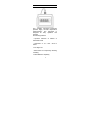
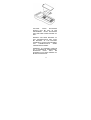
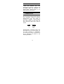
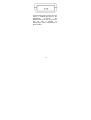
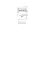
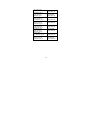
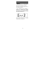
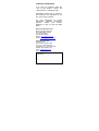
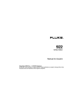
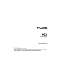
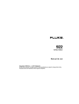
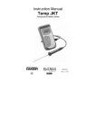
Thermocouple
Thermometer Models
60010-00 (Type J)
60010-10 (Type K)
60010-20 (Type T)
Technology Made Easy ...
68X309905 Rev 1 04/04
TABLE OF CONTENTS
1.
2.
3.
4.
5.
6.
7.
8.
9.
10.
11.
12.
13.
14.
15.
16.
17.
18.
19.
20.
INTRODUCTION
4
SAFETY PRECAUTIONS
6
SPECIFICATIONS
7
BATTERY INSTALLATION AND
REPLACEMENT
10
SELF TEST
12
CONNECTING A THERMOCOUPLE
12
SELECTING TEMPERATURE
SCALE
16
HOLD FUNCTON
17
CALIBRATION
17
CANCELING A FIELD CALIBRATION
18
FIELD CALIBRATION LOCKOUT
AND RE-ENABLE
19
LOCKOUT PROCEDURE
19
RE-ENABLE PROCEDURE
20
MAINTENANCE
20
CLEANING
21
BATTERIES
21
ACCESSORIES
22
SERVICE
24
WARRANTY
25
PRODUCT RETURN
25
1.
INTRODUCTION
This versatile hand-held instrument
provides highly accurate temperature
measurements. The instrument is
designed for easy operation and
includes
the following features:
• Operator selection of Celsius or
Fahrenheit scale
• Resolution of 0.1° from –99.9 to
299.9°
• Four-digit LCD
• Hold feature for temporarily retaining
a reading
• Field calibration capability
4
• Low battery warning
• Built-in tilt stand for easy hands-free
operation
• Two blade
connector input
female
ANSI
mini-
• Operates with a wide selection of
probes 2
5
2.
SAFETY PRECAUTIONS
WARNING: THIS INSTRUMENT IS
DESIGNED TO ACCEPT LOW
LEVEL SIGNALS SUPPLIED BY
STANDARD
THERMOCOUPLES.
UNDER
NO
CIRCUMSTANCES
SHOULD THE INPUT VOLTAGE
EXCEED THE SPECIFIED 50V RMS.
CAUTION: DO NOT USE OR STORE
THIS INSTRUMENT IN MICROWAVE
OVENS OR ANY ABNORMALLY HOT
OR COLD AREAS.
CAUTION:
WEAK BATTERIES
SHOULD NOT BE LEFT IN THE
INSTRUMENT. DEAD BATTERIES
CAN LEAK AND CAUSE DAMAGE TO
UNIT.
DANGER: VOLTAGES PRESENT AT
THE THERMOCOUPLE MAY ALSO
BE PRESENT AT THE BATTERY
TERMINALS. ALWAYS DISCONNECT
THE
THERMOCOUPLE
WHEN
CHANGING BATTERIES.
WARNING: TO PREVENT IGNITION
OF A HAZARDOUS ATMOSPHERE,
BATTERIES
MUST
ONLY
BE
CHANGED IN AN AREA KNOWN TO
BE NON-HAZARDOUS.
6
3.
SPECIFICATIONS
THERMOCOUPLE PROBES
Type
Temperature range
Type J
–200°C to 1000°C
(–328°F to 1832°F )
–250°C to 1372°C
(–418°F to 2501°F )
–250°C to 400°C
(–418°F to 752°F )
Type K
Type T
Out
of
range
display:
-
-
-
-
Resolution
0.1°/1° autoranging, 0.1° from –99.9° to
299.9°, 1° outside this range.
Accuracy
> –99.9°: +(0.2% of reading +0.5°C)
+(0.2% of reading +0.9°F)
< –99.9°: +(0.25% of reading, +1°C)
+(0.25% of reading +2°F)
Display
4-digit LCD with 0.5 in high numerals.
Display update rate
0.6 sec per update.
Input
One
thermocouple
connector.
7
with
ANSI
Input Protection
50V rms
Battery
Two AA, 1.5V alkaline ANSI-L40, IECLR6.
Battery Life: 750 hours continuous,
typical.
Low battery indication
Battery Symbol on when 8 to 10 hours
of battery life remains.
Battery symbol blinking: replace battery
Operating Conditions
Stated accuracy:
18°C to 28°C (64°F to 82°F)
Useful range:
0°C to 40°C (32°F to 104°F)
Storage:
–40°C to 65°C (–40°F to 149°F)
Humidity (non-condensing):
10% to 90% 4
Dimensions
3 cm D x 8.4 cm W x 15.8 cm H
(1.2 in x 3.3 in x 6.2 in)
Weight with batteries
227 grams (8 ounces)
8
Ingress protection
Meets IEC-529 IP-54 for dust and
water resistant enclosures.
Intrinsic safety
This product is energy limited for
intrinsically safe operation in hydrogen
atmospheres per Class I, Division 1,
Groups
A,
B,
C
and
D
hazardous(classified) locations for UL
per UL913 and CSA per C22.2 No. 0M1982 and No. 157-M1987. Maximum
surface temperature: 135°C (T4); UL
file No. E182612 (1997).
Electromagnetic Compatibility
(For CE Mark) EN61326-1/1A: 1998
(EU EMC Directive)
9
4.
BATTERY INSTALLATION AND
REPLACEMENT
If battery indicator turns on, battery
life is approximately 8 to 10 hours. The
battery indicator will start blinking with
less than 1 hour of life remaining.
Selected settings are stored in memory
and will remain in memory even after
power is turned off, or while batteries
are being replaced.
1. Before changing battery, turn
instrument
off
and
disconnect
thermocouple.
2. Loosen screw and lift battery cover
off back of case.
3. Remove the two AA batteries.
4. Insert two new batteries observing
polarity.
5. Install cover and tighten screw.
10
CAUTION:
WEAK
BATTERIES
SHOULD NOT BE LEFT IN THE
INSTRUMENT. DEAD BATTERIES
CAN LEAK AND CAUSE DAMAGE TO
UNIT.
DANGER: VOLTAGES PRESENT AT
THE THERMOCOUPLE MAY ALSO
BE PRESENT AT THE BATTERY
TERMINALS. ALWAYS DISCONNECT
THE
THERMOCOUPLE
WHEN
CHANGING BATTERIES.
WARNING: TO PREVENT IGNITION
OF A HAZARDOUS ATMOSPHERE,
BATTERIES
MUST
ONLY
BE
CHANGED IN AN AREA KNOWN TO
BE NON-HAZARDOUS.
11
5.
SELF TEST
Press the ON/OFF key. The
thermometer performs a self-test and
all display digits and indicators, as
shown below, should remain on for
approximately one second.
6.
CONNECTING A
THERMOCOUPLE
Use the correct thermocouple type for
your instrument. Using an incorrect
thermocouple type will result in
erroneous readings. Thermocouples
are colour coded by type using the
North American ANSI Color Code as
follows:
TYPE
J
K
T
COLOR
Black
Yellow
Blue
Thermocouple connectors have one
wide blade and one narrow blade. Do
not force connector in backwards.
Connect thermocouple to receptacle at
top of instrument as shown in the
following illustration.
12
Thermocouple wiring polarity must be
correct. If readings decrease as the
temperature
increases,
the
thermocouple wires may be reversed.
The red wire is negative for
thermocouple wires manufactured in
North America.
13
14
15
If a thermocouple is not connected or if
the thermocouple is defective, the
display will indicate OPEn.
Thermocouples are sensitive at the tip
or measuring junction. When taking
measurements, allow time for the
reading to stabilize. Multiplying the time
constant of the probe by 5 will give you
the approximate time required.
7.
SELECTING TEMPERATURE
SCALE
Select °C or °F by pressing the °C/°F
key. Each time the key is pressed the
temperature scale will switch. Switching
between °C and °F can be done at any
time during operation.
Each time you turn the instrument on, it
will power up with the same settings
that were set when the unit was last
turned off.
16
8.
HOLD FUNCTON
Press the HOLD key to retain the
reading on the display. Press the
HOLD key again for normal operation.
9.
CALIBRATION
The thermometer is factory calibrated
and does not require calibration before
use. The CAL function allows single
point calibration of the thermometer, at
0°C (32°F) to compensate for
thermocouple off-set error. It is not
necessary to perform a field calibration
to obtain specified meter accuracy. Use
the field calibration feature to improve
thermometer/probe accuracy or to
compensate for thermocouple drift.
.
1. Pack sensing end of probe in a
container tightly packed with crushed
ice and filled with distilled water. Allow
temperature to stabilize.
2. Press and hold the CAL key for 5
seconds to enter the calibration mode,
the CAL annunciator on the display
starts blinking. Release the CALkey.
3. If the measured temperature is from
_10°C to10°C (14 to 50°F), when the
17
temperature reading is stable, press
the CAL key.
The CAL indicator will stop blinking
and the reading will be set to 0°C
(32°F). The CAL indicator will remain
turned on, indicating a field calibration
is active.
If “Err” is displayed, either the displayed
reading is outside the above limits or
the batteries are weak.
10. CANCELING A FIELD
CALIBRATION
1. Turn the thermometer off.
2. Hold the CAL key down while
pressing the ON/OFF key.
The field calibration is canceled and the
thermometer reverts to the default
factory
calibration.
The
CAL
annunciator is now turned off.
18
11. FIELD CALIBRATION LOCKOUT
AND RE-ENABLE
The calibration lockout feature prevents
any field calibration changes. The
lockout remains in effect until a lockout
re-enable has been performed. Use
the following procedures to lockout or
re-enable the field calibration operation.
12. LOCKOUT PROCEDURE
1. Turn the thermometer off.
2. Simultaneously press and hold the
CAL and the °C/°F keys down and
momentarily press the ON/OFF key.
Continue to hold the CAL and °C/°F
keys for at least 5 seconds.
19
13. RE-ENABLE PROCEDURE
1. Turn the thermometer off.
2. Simultaneously press and hold the
HOLD and the CAL keys down and
momentarily press the ON/OFF key.
Continue to hold the HOLD and
CAL keys until the display blanks.
14. MAINTENANCE
Properly used, the thermometer should
maintain calibration indefinitely and not
require service other than occasional
cleaning of the housing and changing
of the batteries.
20
15. CLEANING
WARNING:
TO PREVENT IGNITION OFA
HAZARDOUS
ATMOSPHERE BY
ELECTROSTATIC
DISCHARGE,CLEAN WITH DAMP
CLOTH.
Do not clean with abrasives or
solvents. Use mild detergents, never
immerse nor use excessive fluid.
16. BATTERIES
If there is no display when the
thermometer is turned on, check
condition of the two AA batteries. Also
check that the battery terminals are
clean and batteries are properly
installed. If replacement is necessary,
refer to the BATTERY INSTALLATION
AND REPLACEMENT section for
replacement procedure.
21
17. ACCESSORIES
Replacement
Accessories
Meter
and
Meter
Item
Ordering Code
Type J
60010-00
Type K
60010-10
Type T
60010-20
Soft carrying case
08520-05
Replacement AA
batteries, pack of 4
09376-01
Call for part
number
Traceable to
NIST
Certificate of Calibration
22
General purpose
probe (immersion
Into liquids), type J
EC-TPGLPJ01M/ 08517-55
Penetration probe
(meat, semi-soft
Materials), type J
EC-TPPENJ01M/ 08517-65
Surface probe
(direct contact on
Hot surfaces), type J
EC-TPSURJ01M/ 08517-60
Clip-on probe
(surface contactsElectronics), type J
EC-TPCLPJ01M/ 08469-00
General purpose
probe (immersion
Into liquids), type K
EC-TPGLPK01M/ 08516-55
Penetration probe
(meat, semi-soft
Materials), type K
EC-TPPENK01M/ 08516-65
Surface probe
(direct contact on
Hot surfaces), type K
EC-TPSURK01M/ 08516-60
Clip-on probe
(surface contactsElectronics), type K
EC-TPCLPK01M / 08469-02
23
18. SERVICE
WARNING
SUBSTITUTION OF COMPONENTS
MAY IMPAIR INTRINSIC SAFETY.
There are no internal adjustments or
user replaceable parts.
If “Err” followed by the numbers 1
through 9 is displayed (see example
below) return unit for service. Note that
“Err” alone may be displayed during
improper field calibration.
Note: Serial number label is located
inside battery compartment.
24
19. WARRANTY
The Manufacturer warrants this
product to be free from significant
deviations
from
published
specifications for a period of three
years. If repair or adjustment is
necessary within the warranty period,
the problem will be corrected at no
charge if it is not due to misuse or
abuse on your part as determined by
the Manufacturer. Repair costs outside
the warranty period, or those resulting
from product misuse or abuse, may be
invoiced to you.
20. PRODUCT RETURN
To limit charges and delays, contact
the seller or Manufacturer for
authorization and shipping instructions
before returning the product, either
within or outside of the warranty period.
When returning the product, please
state the reason for the return. For your
protection, pack the product carefully
and insure it against possible damage
or loss. Any damages resulting from
improper
packaging
are
your
responsibility.
25
NOTES
TECHNICAL ASSISTANCE
If you have any questions about the
use of this product, contact the
Manufacturer or authorized seller.
Trademarks bearing the ® symbol in
this publication are registered in the
U.S. and in other countries.
For more information on Eutech
Instruments/ OAKTON Instruments’
products,
contact
your
nearest
distributor or visit our web site listed
below:
Eutech Instruments Pte Ltd
Blk 55 Ayer Rajah Crescent
#04-16 Singapore 139949
Tel: (65) 6778 6876
Fax: (65) 6773 0836
Website: www.eutechinst.com
Email: [email protected]
OAKTON Instruments
P.O. Box 5136
Vernon Hills, IL 60061, USA
Tel (in U.S.): 888-462-5866
Tel (outside U.S.) 1-847-549-7600
Website: www.4oakton.com
E-mail: [email protected]
Fax: (1) 847-247-2984
Distributed by: