1
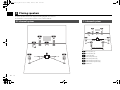
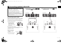
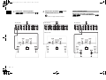
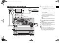
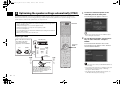
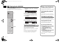
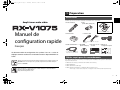
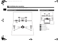
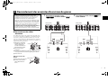
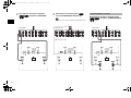
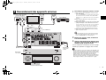
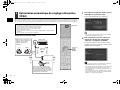
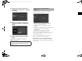
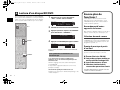
RX-V1075_esg_CA_cover1.fm Page 1 Monday, February 18, 2013 4:35 PM CA English Français AV Receiver/Ampli-tuner audio-vidéo Easy Setup Guide Manuel de configuration rapide RX-V1075_esg_CA.fm Page 1 Monday, March 4, 2013 11:28 AM 1 Preparation Accessories Check that the following accessories are supplied with the product. AV Receiver Remote control Batteries (AAA, R03, UM-4) (x2) Insert the batteries the right way round. Easy Setup Guide AM antenna FM antenna YPAO microphone English *One of the above is supplied depending on the region of purchase. Power cable This document explains how to set up a 5.1- or 7.1-channel system and play back surround sound from a BD/DVD on the unit. To reduce the impact on natural resources, the Owner’s Manual for this product is supplied on CD-ROM. For more information about this product, refer to the Owner’s Manual on the supplied CD-ROM. CD-ROM Safety Brochure (Owner’s Manual) Easy Setup Guide *The supplied power cable varies depending on the region of purchase. Cables required for connections The following cables (not supplied) are required to build the system described in this document. • Speaker cables (depending on the number of speakers) • HDMI cable (x2) • Audio pin cable (x1) PDF versions of this guide and “Owner’s Manual” can be downloaded from the following website. http://download.yamaha.com/ • Digital optical cable or stereo pin cable (x1*) * Not required if your TV supports ARC (Audio Return Channel) En 1 RX-V1075_esg_CA.fm Page 2 Monday, March 4, 2013 11:28 AM 2 Placing speakers Set up the speakers in the room using the following diagram as a reference. For information on other speaker systems, refer to “Owner’s Manual”. 5.1-channel system 7.1-channel system 1 9 1 2 2 3 4 5 10° to 30° 9 3 10° to 30° 6 7 0.3 m (1 ft) or more 1 Front speaker (L) 4 5 10° to 30° 10° to 30° 2 Front speaker (R) 3 Center speaker 4 Surround speaker (L) 5 Surround speaker (R) 6 Surround back speaker (L) 7 Surround back speaker (R) 9 Subwoofer 2 En RX-V1075_esg_CA.fm Page 3 Monday, March 4, 2013 11:28 AM 3 Connecting speakers/subwoofer • Under its default settings, the unit is configured for 8-ohm speakers. When connecting 6-ohm speakers, set the unit’s speaker impedance to “6 MIN”. For details, see “Setting the speaker impedance” in “Owner’s Manual”. 1 Connect the front speakers (1/2) to the FRONT (//\) terminals. 2 Connect the center speaker (3) to the CENTER terminal. • Use a subwoofer equipped with built-in amplifier. • Before connecting the speakers, remove the unit’s power cable from the AC wall outlet and turn off the subwoofer. • Ensure that the core wires of the speaker cable do not touch each other or come into contact with the unit’s metal areas. This may damage the unit or the speakers. If the speaker cables short circuit, “Check SP Wires” will appear on the front display when the unit is turned on. ZONE OUT CENTER PRE OUT (SINGLE) 2 The unit (rear) ROUND SUR. BACK SUBWOOFER ZONE 2 FRONT SURROUND SUR. BACK SUBWOOFER ZONE OUT CENTER 1 SURROUND L R ■ Connecting speaker cables SURROUND BACK (SINGLE) SURROUND SUR. BACK 1 2 The unit (rear) CENTER ROUND SUR. BACK SUBWOOFER ZONE 2 FRONT SPEAKERS R PRE OUT SUBWOOFER CENTER SPEAKERS L CENTER R FRONT L R ZONE 2/F.PRESENCE/ BI–AMP EXTRA SP L R SURROUND L R SINGLE SURROUND BACK L CENTER R FRONT L R ZONE 2/F.PRESENCE/ BI–AMP EXTRA SP L SINGLE Speaker cables have two wires. One is for connecting the negative (–) terminals of the unit and the speaker, and the other is for the positive (+) terminals. If the wires are colored to prevent confusion, connect the black wire to the negative and the other wire to the positive terminals. a Remove approximately 10 mm (3/8”) of insulation from the ends of the speaker cable and twist the bare wires of the cable firmly together. + (red) + b 1 c 2 1 2 FR ON T - 9 a d 3 9 3 – (black) b Loosen the speaker terminal. 4 5 4 5 c Insert the bare wires of the cable into the gap on the side (upper right or bottom left) of the terminal. d Tighten the terminal. Using a banana plug a Tighten the speaker terminal. b Insert a banana plug into the end of the terminal. Banana plug a + FR ON T b En 3 RX-V1075_esg_CA.fm 3 Page 4 Monday, March 4, 2013 11:28 AM Connect the surround speakers (4/5) to the SURROUND (//\) terminals. 4 For 7.1-channel system Connect the subwoofer (9) to the SUBWOOFER PREOUT (1) jack. Connect the surround back speakers (6/7) to the SURROUND BACK (//\) terminals. • Use a subwoofer equipped with built-in amplifier. ZONE OUT CENTER PRE OUT (SINGLE) 2 The unit (rear) ROUND SUR. BACK SUBWOOFER ZONE 2 FRONT SURROUND SUR. BACK SUBWOOFER ZONE OUT CENTER 1 SURROUND L R SURROUND BACK (SINGLE) The unit (rear) CENTER ROUND SUR. BACK SUBWOOFER ZONE 2 FRONT SURROUND SUR. BACK SUBWOOFER ZONE OUT CENTER 1 2 SPEAKERS R PRE OUT CENTER R FRONT L R ZONE 2/F.PRESENCE/ BI–AMP EXTRA SP L R SURROUND L R SINGLE SURROUND BACK (SINGLE) SURROUND SUR. BACK 1 2 The unit (rear) CENTER ROUND SUR. BACK SUBWOOFER ZONE 2 FRONT SPEAKERS L PRE OUT SUBWOOFER CENTER SPEAKERS L CENTER R FRONT L R ZONE 2/F.PRESENCE/ BI–AMP EXTRA SP L R SURROUND L R SURROUND BACK SINGLE L CENTER R FRONT L R ZONE 2/F.PRESENCE/ BI–AMP EXTRA SP SINGLE Audio pin cable 1 9 4 2 1 3 9 5 4 2 1 3 9 5 En 3 4 5 6 4 2 7 L RX-V1075_esg_CA.fm Page 5 Monday, March 4, 2013 11:28 AM 1 4 Connecting external devices Audio out (digital optical or analog stereo) OPTICAL R TV HDMI in HDMI out HDMI HDMI BD/DVD player L Connect external devices to the unit. a Connect a BD/DVD player to the unit with an HDMI cable. If the BD/DVD player is currently connected to the TV directly with an HDMI cable, disconnect the cable from the TV and connect it to the unit. b Connect a TV to the unit with the other HDMI cable. HDMI O R L a b c HDMI OUT 1 jack HDMI HDMI HDMI OUT 1 DC OUT 5V 0.5A (ZONE OUT) NETWORK AV 3 HDMI HDMI OUT ( 3 NET ) 2 ARC AV 2 HDMI (AV 1) jack (1 BD/DVD) 1 AV 1 AV 4 (1 BD/DVD) (ZONE OUT) MONITOR OUT/ ZONE OUT AV OUT d Connect the supplied power cable to the unit and then to an AC wall outlet. AV 1 2 ARC PHONO c Connect a TV to the unit with a digital optical cable or a stereo pin cable. This connection is required to play back TV audio on the unit. This connection is not required if your TV supports ARC (Audio Return Channel). HDMI Y AV 1 AV 2 AV 3 RS-232C AV 4 AV 5 AV 6 PB COMPONENT VIDEO PR Y AV 3 PB C TRIGGER OUT PR AV 1 A Y GND 1 REMOTE MONITOR OUT/ZONE OUT PB PR IN OUT AV 2 D AV 4 AUDIO 1 (2 TV) L 2 B AUDIO 1 (2 TV) AUDIO 2 AUDIO 3 • For information on how to connect radio antennas or other external devices, see “PREPARATIONS” in “Owner’s Manual”. AV 7 (1 BD/DVD) AUDIO 4 MULTI CH INPUT 12V ZONE OUT CENTER PRE OUT (SINGLE) 0.1A 1 L R 2 Turn on the unit, the TV and the BD/DVD player. 3 Use the TV remote control to change the TV input to video from the unit. 2 1 COAXIAL 2 COAXIAL 3 OPTICAL 4 OPTICAL 5 OPTICAL 6 COAXIAL FRONT SURROUND SUR. BACK SUBWOOFER ZONE 2 FRONT SURROUND SUR. BACK SUBWOOFER CENTER SPEAKERS R SURROUND L R SURROUND BACK L CENTER R FRONT L R ZONE 2/F.PRESENCE/ BI–AMP EXTRA SP AC IN L R ANTENNA (4 RADIO) 5 OPTICAL AM FM 75Ω SINGLE O The unit (rear) AUDIO 1 (OPTICAL or AUDIO) jack d The connections are complete. Proceed to the next page to optimize the speaker settings. To an AC wall outlet MAIN ZONE PURE DIRECT Turn on the unit • By connecting a TV to the unit with an HDMI cable, you can configure the unit’s settings with the menu displayed on the TV. In addition, you can select the on-screen menu language from English (default), Japanese, French, German, Spanish, Russian, Italian and Chinese. For details, refer to “Owner’s Manual”. In this guide, illustrations of English menu screens are used as examples. VOLUME INPUT Press the bottom of the front panel door gently to open the door The unit (front) En 5 RX-V1075_esg_CA.fm Page 6 Monday, March 4, 2013 11:28 AM 5 Optimizing the speaker settings automatically (YPAO) 1 The following screen appears on the TV. The Yamaha Parametric room Acoustic Optimizer (YPAO) function detects speaker connections, measures the distances from them to your listening position(s), and then automatically optimizes the speaker settings, such as volume balance and acoustic parameters, to suit your room. • During the measuring process, test tones are output at high volume. Ensure that the test tones do not frighten small children. Also, refrain from using this function at night when it may be a nuisance to others. Connect the YPAO microphone to the YPAO MIC jack on the front panel. RECEIVER SOURCE RECEIVER AV 1 2 3 4 5 6 7 V-AUX 1 2 3 4 PHONO MULTI USB NET PARTY HDMI OUT • During the measuring process, you cannot adjust the volume. • During the measuring process, keep the room as quiet as possible. • Do not connect headphones. • Do not stand between the speakers and the YPAO microphone during the measurement process (about 3 minutes). • Move to the corner of the room or leave the room. AUDIO TUNER MAIN ZONE 2 • To cancel the operation, disconnect the YPAO microphone before starting the measurement. SCENE Preparing for YPAO Turn on the subwoofer and set the volume to half. If the cross-over frequency is adjustable, set it to maximum. 1 2 3 4 BD/DVD TV NET RADIO YPAO MIC TOP MENU POP-UP/MENU ON SCREEN Cursor keys ENTER RETURN CROSSOVER/ HIGH CUT RETURN To start the measurement, use the cursor keys to select “Measure” and press ENTER. The measurement will start in 10 seconds. OPTION ENTER VOLUME 2 VOLUME MUTE PROGRAM The unit (front) The following screen appears on the TV when the measurement finishes. DISPLAY BAND MODE TUNING PRESET SUR. DECODE STRAIGHT MIN MAX MIN MAX MOVIE MUSIC INFO SLEEP ENHANCER PURE DIRECT YPAO microphone 1 2 3 5 6 7 9 0 4 8 MEMORY 10 ENT TV INPUT TV VOL Ear height Place the YPAO microphone at your listening position (same height as your ears). We recommend the use of a tripod as a microphone stand. You can use the tripod screws to fix the microphone in place. 6 En MUTE TV CH CODE SET • If the cursor keys do not work, press RECEIVER and then use the cursor keys. • If any error message (such as E-1) or warning message (such as W-2) appears, see “Error messages” or “Warning messages” in “Owner’s Manual”. • If the warning message “W-1:Out of Phase” appears, see “If “W-1:Out of Phase” appears” (next page). RX-V1075_esg_CA.fm 3 4 Page 7 Monday, March 4, 2013 11:28 AM Use the cursor keys to select “Save/Cancel” and press ENTER. Use the cursor keys to select “SAVE” and press ENTER. If “W-1:Out of Phase” appears Follow the procedure below to check the speaker connections. a Use the cursor keys to select “Result” and press ENTER. b Use the cursor keys to select “Wiring”. c Check the cable connections (+/–) of the speaker that was identified as being “Reverse” in the warning message. If the speaker is connected correctly: Depending on the type of speakers or room environment, this message may appear even if the speakers are connected correctly. In this case, you can ignore the message. 5 Disconnect the YPAO microphone from the unit. This completes optimization of the speaker settings. Press RETURN and proceed to step 3. If the speaker is connected incorrectly: Turn off the unit, reconnect the speaker cable, and then try YPAO measurement again. • The YPAO microphone is sensitive to heat, so should not be placed anywhere where it could be exposed to direct sunlight or high temperatures (such as on top of AV equipment). En 7 RX-V1075_esg_CA.fm Page 8 Monday, March 4, 2013 11:28 AM 6 Playing back a BD/DVD Now let’s play back a BD/DVD. We recommend playing back multichannel audio (5.1-channel or more) to feel surround sound produced by the unit. Many more features! 1 SPIMP.- DOCK TAG HD STEREO TUNED PRE AMP PARTY ZONE ZONE ZONE 3 4 IN OUT 1 OUT 2 2 ENHANCER SLEEP RECEIVER SOURCE Press AV 1 to select “AV 1” as the input source. HD 3 AV1 A.Sel:Auto MUTE VOLUME ADAPTIVE DRC PL L C R PR SL SW1 SW SW2 SR PL SBL SB SBR PR AV 1 2 3 4 5 6 7 V-AUX 1 2 3 4 PHONO MULTI USB NET PARTY HDMI OUT AV 1 AUDIO 2 3 TUNER MAIN ZONE 2 Start playback on the BD/DVD player. Press STRAIGHT repeatedly to select “STRAIGHT”. SPIMP.- DOCK TAG HD STEREO TUNED PRE AMP PARTY ZONE ZONE ZONE 3 4 IN OUT 1 OUT 2 2 ENHANCER SLEEP SCENE 1 2 3 4 HD 3 BD/DVD TV NET VOLUME MUTE PROGRAM TOP MENU RADIO VOLUME SPIMP.- OPTION MUTE VOLUME ADAPTIVE DRC PL L C R PR SL SW1 SW SW2 SR PL SBL SB SBR PR Main:Volume HD 3 MUTE VOLUME ADAPTIVE DRC PL L C R PR SL SW1 SW SW2 SR PL SBL SB SBR PR This completes the basic setup procedure. DISPLAY BAND If surround sound is not working MODE TUNING PRESET SUR. DECODE STRAIGHT MOVIE MUSIC INFO SLEEP ENHANCER PURE DIRECT 1 2 3 4 5 6 7 8 9 0 STRAIGHT Sound is only being output from the front speakers during multichannel audio playback Check the digital audio output setting on the BD/DVD player. MEMORY 10 ENT TV It may be set to 2-channel output (such as PCM). INPUT TV VOL MUTE TV CH CODE SET Connecting other playback devices Connect audio devices (such as CD player), game consoles, camcorders, and many others. Selecting the sound mode Select the desired sound program (CINEMA DSP) or surround decoder suitable for movies, music, games, sports programs, and other uses. Playing back from iPod ENTER RETURN Please refer to “Owner’s Manual” on the supplied CD-ROM to help you get the most out of the unit. Press VOLUME to adjust the volume. DOCK TAG HD STEREO TUNED PRE AMP PARTY ZONE ZONE ZONE 3 4 IN OUT 1 OUT 2 2 ENHANCER SLEEP POP-UP/MENU ON SCREEN 4 STRAIGHT A.Sel:Auto The unit has various other functions. No sound is coming from a specific speaker See “Troubleshooting” in “Owner’s Manual”. By using a USB cable supplied with iPod, you can enjoy iPod music on the unit. ■ Listening to FM/AM radio ■ Playing back music stored on a USB storage device ■ Playing back the network contents ■ Selecting the input source and favorite settings at once For more information, see “What you can do with the unit”. 8 En RX-V1075_esg_CA.fm Page 1 Thursday, March 21, 2013 11:35 AM UAB 1 Préparation Accessoires Vérifiez que les accessoires suivants sont fournis avec le produit. Ampli-tuner audio-vidéo Télécommande Piles (AAA, R03, UM-4) (x2) Insérez les piles comme indiqué. Manuel de configuration rapide Français Ce document décrit la configuration d’un système à 5.1 ou 7.1 voies et explique comment restituer le son d’ambiance d’un disque BD/DVD sur l’unité. Afin de préserver l’environnement, le Mode d’emploi de ce produit est fourni sur CD-ROM. Pour en savoir plus sur ce produit, reportez-vous au Mode d’emploi fourni sur CD-ROM. Pour télécharger ce guide ainsi que le « Mode d’emploi » au format PDF, rendez-vous sur le site Web suivant : http://download.yamaha.com/ Antenne AM Antenne FM Microphone YPAO *L’élément fourni dépend de la région d’achat. Câble d’alimentation CD-ROM Brochure sur la Manuel de (Mode d’emploi) sécurité configuration rapide *Le câble d’alimentation fourni dépend de la région d’achat. Câbles requis pour les raccordements Les câbles suivants (non fournis) sont requis pour l’installation du système décrit dans le présent document. • Câbles d’enceintes (en fonction du nombre d’enceintes) • Câble HDMI (x2) • Câble de broche audio (x1) • Câble optique numérique ou câble de broche stéréo (x1*) * Non requis si votre téléviseur prend en charge la fonction ARC (Audio Return Channel). Fr 1 RX-V1075_esg_CA.fm Page 2 Thursday, March 21, 2013 11:35 AM 2 Installation des enceintes Installez les enceintes dans la pièce en vous reportant au diagramme suivant. Pour obtenir des informations sur les autres systèmes d’enceinte, consultez le « Mode d’emploi ». Système à 5.1 voies Système à 7.1 voies 1 9 1 2 2 3 4 5 10° à 30° 9 3 10° à 30° 6 7 0,3 m ou plus 1 Enceinte avant (G) 4 5 10° à 30° 10° à 30° 2 Enceinte avant (D) 3 Enceinte centrale 4 Enceinte Surround (G) 5 Enceinte Surround (D) 6 Enceinte Surround arrière (G) 7 Enceinte Surround arrière (D) 9 Caisson de graves 2 Fr RX-V1075_esg_CA.fm Page 3 Thursday, March 21, 2013 11:35 AM 3 Raccordement des enceintes/du caisson de graves • L’unité est configurée pour des enceintes 8 ohms par défaut. Lorsque vous raccordez des enceintes 6 ohms, réglez l’impédance d’enceinte de l’unité sur « 6 MIN ». Pour plus d’informations, reportez-vous à la section « Réglage de l’impédance des enceintes » du « Mode d’emploi ». 1 Raccordez les enceintes avant (1/2) aux bornes FRONT (//\). 2 Raccordez l’enceinte centrale (3) à la borne CENTER. • Utilisez un caisson de graves équipé d’un amplificateur intégré. • Avant de raccorder les enceintes, retirez le câble d’alimentation de l’unité de la prise secteur et éteignez le caisson de graves. • Veillez à ce que les fils conducteurs du câble de l’enceinte ne se touchent pas ou n’entrent pas en contact avec les parties métalliques de l’unité. Ce contact risque d’endommager l’unité ou les enceintes. Si un court-circuit survient au niveau des câbles de l’enceinte, le message « Check SP Wires » apparaît sur l’afficheur de la face avant lors de la mise sous tension de l’unité. ZONE OUT CENTER PRE OUT (SINGLE) 2 L’unité (arrière) ROUND SUR. BACK SUBWOOFER ZONE 2 FRONT SURROUND SUR. BACK SUBWOOFER ZONE OUT CENTER 1 SURROUND L R SURROUND BACK (SINGLE) SURROUND SUR. BACK 1 2 L’unité (arrière) CENTER ROUND SUR. BACK SUBWOOFER ZONE 2 FRONT SPEAKERS R PRE OUT SUBWOOFER CENTER SPEAKERS L CENTER R FRONT L R ZONE 2/F.PRESENCE/ BI–AMP EXTRA SP L R SURROUND L R SINGLE SURROUND BACK L CENTER R FRONT L R ZONE 2/F.PRESENCE/ BI–AMP EXTRA SP L SINGLE ■ Raccordement des câbles d’enceinte Les câbles d’enceinte sont composés de deux fils. L’un se connecte aux bornes négatives (-) de l’appareil et de l’enceinte, et l’autre aux bornes positives (+). Si les fils sont de couleurs différentes afin d’éviter toute confusion, connectez le fil de couleur noire aux bornes négatives et l’autre fil aux bornes positives. a Dénudez les extrémités c + du câble d’enceinte sur + (rouge) b environ 10 mm, puis torsadez fermement les a brins dénudés du câble. d b Desserrez la borne – (noir) d’enceinte. c Insérez les fils dénudés du câble dans l’écartement sur le côté (supérieur droit ou inférieur gauche) de la borne. d Serrez la borne. 1 9 2 1 3 9 2 3 FR ON T Utilisation d’une fiche banane a Serrez la borne d’enceinte. Fiche banane b Insérez la fiche banane dans l’extrémité de la borne. a + 4 5 4 5 FR ON T b Fr 3 RX-V1075_esg_CA.fm 3 Page 4 Thursday, March 21, 2013 11:35 AM 4 Raccordez les enceintes d’ambiance (4/5) aux bornes SURROUND (//\) . Raccordez le caisson de graves (9) à la prise SUBWOOFER PREOUT (1). • Utilisez un caisson de graves équipé d’un amplificateur intégré. ZONE OUT CENTER PRE OUT (SINGLE) 2 L’unité (arrière) ROUND SUR. BACK SUBWOOFER ZONE 2 FRONT SURROUND SUR. BACK SUBWOOFER ZONE OUT CENTER 1 SURROUND L R SURROUND BACK (SINGLE) ROUND SUR. BACK SUBWOOFER ZONE 2 SURROUND SUR. BACK SUBWOOFER ZONE OUT CENTER 2 FRONT Raccordez les enceintes surround arrière (6/7) aux bornes SURROUND BACK (//\). 1 L’unité (arrière) CENTER SPEAKERS R PRE OUT Pour le système à 7.1 voies CENTER R FRONT L R ZONE 2/F.PRESENCE/ BI–AMP EXTRA SP L R SURROUND L R SINGLE SURROUND BACK (SINGLE) SURROUND SUR. BACK 1 2 L’unité (arrière) CENTER ROUND SUR. BACK SUBWOOFER ZONE 2 FRONT SPEAKERS L PRE OUT SUBWOOFER CENTER SPEAKERS L CENTER R FRONT L R ZONE 2/F.PRESENCE/ BI–AMP EXTRA SP L R SURROUND L R SURROUND BACK SINGLE L CENTER R FRONT L R ZONE 2/F.PRESENCE/ BI–AMP EXTRA SP SINGLE Câble de broche audio 1 9 4 2 1 3 9 5 4 2 1 3 9 5 Fr 3 4 5 6 4 2 7 L RX-V1075_esg_CA.fm Page 5 Thursday, March 21, 2013 11:35 AM 1 4 Raccordement des appareils externes TV Sortie audio (optique numérique ou stéréo analogique) OPTICAL R Entrée HDMI Sortie HDMI HDMI HDMI Lecteur BD/DVD L HDMI O R L HDMI a b c Prise HDMI OUT 1 HDMI HDMI HDMI OUT 1 DC OUT 5V 0.5A AV 1 2 NETWORK 2 ARC AV 1 AV 2 AV 3 HDMI HDMI OUT ( 3 NET ) 1 PHONO Prise HDMI (AV 1) (1 BD/DVD) (ZONE OUT) ARC AV 4 MONITOR OUT/ ZONE OUT AV OUT (1 BD/DVD) (ZONE OUT) Y AV 1 AV 2 AV 3 PB COMPONENT VIDEO PR Y AV 3 PB C AV 5 AV 6 AV 7 GND MONITOR OUT/ZONE OUT PB PR 1 REMOTE IN OUT AV 2 2 B AUDIO 1 D AV 4 AUDIO 1 (2 TV) L (2 TV) AUDIO 2 AUDIO 3 • Pour plus d’informations sur le raccordement des antennes radio ou des autres appareils externes, reportez-vous à la section « PRÉPARATION » du « Mode d’emploi ». TRIGGER OUT PR AV 1 Y AUDIO 4 MULTI CH INPUT 12V ZONE OUT CENTER PRE OUT (SINGLE) SURROUND SUR. BACK 2 3 0.1A 1 L R 2 1 COAXIAL 2 COAXIAL 3 OPTICAL 4 OPTICAL 5 OPTICAL 6 COAXIAL FRONT SURROUND SUR. BACK SUBWOOFER ZONE 2 FRONT SUBWOOFER CENTER SPEAKERS R SURROUND L R SURROUND BACK L CENTER R FRONT L R ZONE 2/F.PRESENCE/ BI–AMP EXTRA SP AC IN L R ANTENNA (4 RADIO) 5 OPTICAL AM a Raccordez un lecteur BD/DVD à l’unité au moyen d’un câble HDMI. Si le lecteur BD/DVD est actuellement directement raccordé au téléviseur à l’aide d’un câble HDMI, débranchez ce câble du téléviseur et raccordez-le à l’unité. b Raccordez un téléviseur à l’unité au moyen de l’autre câble HDMI. c Raccordez le téléviseur et l’unité au moyen d’un câble optique numérique ou d’un câble de broche stéréo. Ce raccordement est nécessaire si vous souhaitez restituer le son TV sur l’unité. Ce raccordement n’est pas nécessaire si votre téléviseur prend en charge la fonction ARC (Audio Return Channel). d Raccordez le câble d’alimentation fourni à l’unité, puis à une prise secteur. RS-232C AV 4 (1 BD/DVD) A Raccordez les appareils externes à l’unité. FM 75Ω Mettez sous tension, l’unité, le téléviseur et le lecteur BD/DVD. Utilisez la télécommande du téléviseur pour changer la source d’entrée du téléviseur et afficher l’image à partir de l’unité. SINGLE O L’unité (arrière) Prise AUDIO 1 (OPTICAL ou AUDIO) d Les raccordements sont terminés. Passez à la page suivante pour optimiser les réglages des enceintes. Branchement sur une prise secteur MAIN ZONE PURE DIRECT Mettre l’unité sous tension VOLUME INPUT Pour ouvrir le clapet de la face avant, appuyez doucement au bas du clapet • Lorsque le téléviseur est raccordé à l’unité par un câble HDMI, vous pouvez configurer les réglages de cette dernière à l’aide du menu qui s’affiche sur le téléviseur. Par ailleurs, vous pouvez sélectionner la langue souhaitée dans le menu affiché à l’écran parmi les langues suivantes : anglais (par défaut), japonais, français, allemand, espagnol, russe, italien et chinois. Pour plus d’informations, reportez-vous au « Mode d’emploi ». Des illustrations d’écrans de menus anglais sont utilisées comme exemples dans ce guide. L’unité (avant) Fr 5 RX-V1075_esg_CA.fm Page 6 Thursday, March 21, 2013 11:35 AM 5 Optimisation automatique des réglages d’enceintes (YPAO) 1 Raccordez le microphone YPAO à la prise YPAO MIC sur le panneau avant. L’écran suivant apparaît sur le téléviseur. La fonction Yamaha Parametric room Acoustic Optimizer (YPAO) permet de détecter les raccordements des enceintes et de mesurer la distance entre ces dernières et la position d’écoute. Elle optimise ensuite automatiquement les réglages des enceintes tels que les paramètres d’équilibre du volume et les paramètres acoustiques qui conviennent à la pièce. • Lors de la mesure, des signaux test sont restitués à un volume élevé. Assurez-vous que le signal test n’effraie pas les jeunes enfants. Évitez également d’utiliser cette fonction la nuit, où elle peut constituer une nuisance pour les autres. • Lors de la mesure, vous ne pouvez pas régler le volume. • Faites en sorte que la pièce soit le plus calme possible. • Ne raccordez pas d’écouteurs. • Ne restez pas entre les enceintes et le microphone YPAO pendant la mesure (environ 3 minutes). • Placez-vous dans un coin de la pièce ou quittez-la. RECEIVER SOURCE RECEIVER AV 1 2 3 4 5 6 7 V-AUX 1 2 3 4 PHONO MULTI USB NET PARTY HDMI OUT AUDIO • Pour annuler l’opération, débranchez le microphone YPAO avant le début de l’opération de mesure. TUNER MAIN ZONE 2 Préparation à la fonction YPAO 2 SCENE Allumez le caisson de graves et réglez le volume à moitié. Si la fréquence de coupure est réglable, réglez-la sur le maximum. L’unité (avant) 1 2 3 4 BD/DVD TV NET RADIO YPAO MIC VOLUME MUTE PROGRAM La mesure commence dans les 10 secondes. TOP MENU Lorsque la mesure est terminée, l’écran suivant apparaît sur le moniteur TV. POP-UP/MENU ON SCREEN VOLUME Pour commencer la mesure, utilisez les touches de curseur pour sélectionner « Measure » et appuyez sur ENTER. OPTION CROSSOVER/ HIGH CUT ENTER RETURN DISPLAY Touches de curseur ENTER RETURN BAND MODE MIN MAX MIN MAX TUNING PRESET Microphone YPAO SUR. DECODE STRAIGHT MOVIE MUSIC INFO SLEEP ENHANCER PURE DIRECT 1 2 3 5 6 7 9 0 4 8 MEMORY Hauteur d’oreille 6 Fr ENT TV INPUT TV VOL MUTE Placez le microphone YPAO à votre position d’écoute (à hauteur d’oreilles). Nous conseillons l’utilisation d’un trépied comme support de microphone. Lorsque vous utilisez un trépied, utilisez les vis du trépied pour fixer le microphone. 10 TV CH CODE SET • Si les touches de curseur ne fonctionnent pas, appuyez sur RECEIVER puis utilisez les touches de curseur. • Si un message d’erreur (par exemple E-1) ou d’avertissement (par exemple W-2) apparaît, reportez-vous aux sections « Messages d’erreur » ou « Messages d’avertissement » du « Mode d’emploi ». • Si le message d’avertissement « W-1:Out of Phase » apparaît, reportez-vous à la section « Si le message « W-1:Out of Phase » apparaît » se trouvant à la page suivante. RX-V1075_esg_CA.fm 3 4 Page 7 Thursday, March 21, 2013 11:35 AM Utilisez les touches de curseur pour sélectionner « Save/Cancel » et appuyez sur ENTER. Utilisez les touches de curseur pour sélectionner « SAVE » et appuyez sur ENTER. Si le message « W-1:Out of Phase » apparaît Suivez la procédure ci-dessous pour vérifier les raccordements de l’enceinte. a Utilisez les touches de curseur pour sélectionner « Result » et appuyez sur ENTER. b Utilisez les touches de curseur pour sélectionner « Wiring ». c Vérifiez les raccordements de câble (+ et -) de l’enceinte désignée par « Reverse » dans le message d’avertissement. Si l’enceinte est correctement raccordée : Selon le type d’enceintes ou l’environnement, ce message peut apparaître, même si les enceintes sont correctement raccordées. 5 Dans ce cas, vous pouvez ignorer le message. Débranchez le microphone YPAO de l’unité. L’optimisation des réglages d’enceintes est maintenant terminée. Appuyez sur RETURN et passez à l’étape 3. Si l’enceinte n’est pas correctement raccordée : Mettez l’unité hors tension et raccordez à nouveau le câble d’enceinte, puis essayez à nouveau d’effectuer la mesure YPAO. • Le microphone YPAO est sensible à la chaleur. Ne le placez pas dans un endroit où il pourrait être exposé directement à la lumière du soleil ou à des températures élevées (sur un équipement AV, etc.). Fr 7 RX-V1075_esg_CA.fm Page 8 Thursday, March 21, 2013 11:35 AM 6 Lecture d’un disque BD/DVD Voyons maintenant comment lire un disque BD/DVD. Pour sentir les effets d’ambiance sonore produits par l’unité, nous vous recommandons de lire les disques avec le système audio multivoies (5.1 voies et plus). 1 SPIMP.- DOCK TAG HD STEREO TUNED PRE AMP PARTY ZONE ZONE ZONE 3 4 IN OUT 1 OUT 2 2 ENHANCER SLEEP RECEIVER SOURCE Appuyez sur AV 1 pour sélectionner « AV 1 » comme source d’entrée. HD 3 AV1 A.Sel:Auto MUTE VOLUME ADAPTIVE DRC PL L C R PR SL SW1 SW SW2 SR PL SBL SB SBR PR Encore plus de fonctions ! L’unité propose diverses autres fonctions. Reportez-vous au « Mode d’emploi » sur le CD-ROM fourni pour savoir comment utiliser l’unité de manière optimale. AV 1 2 3 4 5 6 7 V-AUX AV 1 AUDIO 1 2 3 4 PHONO MULTI USB NET PARTY HDMI OUT 2 3 TUNER MAIN ZONE 2 Commencez la lecture sur le lecteur BD/DVD. Raccordement d’autres appareils de lecture Appuyez à plusieurs reprises sur STRAIGHT pour sélectionner « STRAIGHT ». Raccordez des appareils audio (lecteurs CD et autres), consoles de jeux, caméscopes, etc. SPIMP.- DOCK TAG HD STEREO TUNED PRE AMP PARTY ZONE ZONE ZONE 3 4 IN OUT 1 OUT 2 2 ENHANCER SLEEP SCENE 1 2 3 4 HD 3 BD/DVD TV NET VOLUME MUTE PROGRAM TOP MENU RADIO VOLUME SPIMP.- OPTION MUTE VOLUME ADAPTIVE DRC PL L C R PR SL SW1 SW SW2 SR PL SBL SB SBR PR Appuyez sur VOLUME pour régler le volume. DOCK TAG HD STEREO TUNED PRE AMP PARTY ZONE ZONE ZONE 3 4 IN OUT 1 OUT 2 2 ENHANCER SLEEP POP-UP/MENU ON SCREEN 4 STRAIGHT A.Sel:Auto HD 3 Main:Volume MUTE VOLUME ADAPTIVE DRC PL L C R PR SL SW1 SW SW2 SR PL SBL SB SBR PR ENTER RETURN La procédure d’installation de base est maintenant terminée. DISPLAY BAND MODE TUNING PRESET SUR. DECODE STRAIGHT MOVIE MUSIC INFO SLEEP 1 2 5 6 9 0 ENHANCER PURE DIRECT 3 7 4 8 MEMORY 10 ENT TV INPUT TV VOL MUTE TV CH CODE SET STRAIGHT Si le système de son d’ambiance ne fonctionne pas Lors de la lecture à l’aide du système audio multivoies, le son est restitué uniquement par les enceintes avant Vérifiez le réglage de la sortie audio numérique du lecteur BD/DVD. Il est peut-être réglé pour restituer un son à 2 voies (PCM par exemple). Une enceinte spécifique n’émet aucun son Reportez-vous à la section « Guide de dépannage » du « Mode d’emploi ». 8 Fr Sélection du mode sonore Sélectionnez le programme sonore souhaité (CINEMA DSP) ou le décodeur d’ambiance qui convient aux films, à la musique, aux jeux, aux programmes sportifs, etc. Écoute de musique à partir d’un iPod Grâce au câble USB fourni avec l’iPod, vous pouvez écouter votre musique sur l’unité. ■ Écoute d’émission FM/AM ■ Lecture de musique stockée sur un dispositif de stockage USB ■ Lecture de contenus réseau ■ Sélection simultanée de la source et des paramètres favoris Pour plus d’informations, reportez-vous à la section « Fonctions de l’unité ». RX-V1075_esg_CA_cover4.fm Page 2 Monday, February 18, 2013 4:27 PM © 2013 Yamaha Corporation Printed in Malaysia ZF81580