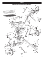
1
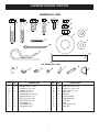
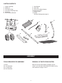
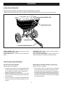
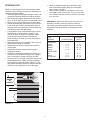
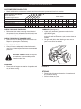
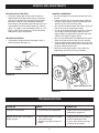
Owner's Manual
®
TOW BROADCAST SPREADER
Model No. 486.245951
CAUTION:
Before using this product, read
this manual and follow all Safety
Rules and Operating Instructions.
STOP
DO NOT RETURN TO STORE
For Missing Parts or Assembly
Questions Call 1-866-576-8388
•
•
•
•
•
Safety
Assembly
Operation
Maintenance
Parts
Sears, Roebuck and Co., Hoffman Estates, IL 60179 U.S.A.
www.sears.com/craftsman
PRINTED IN U.S.A.
FORM NO. 49914 (REV. 05/09/08)
TABLE OF CONTENTS
SAFETY RULES........................................................... 3
FULL SIZE HARDWARE CHART................................. 4
CARTON CONTENTS.................................................. 5
ASSEMBLY................................................................... 5
OPERATION............................................................... 10
MAINTENANCE/STORAGE....................................... 12
SERVICE AND ADJUSTMENTS................................ 13
TROUBLESHOOTING................................................ 13
REPAIR PARTS ILLUSTRATION............................... 14
REPAIR PARTS LIST................................................. 15
PARTS ORDERING/SERVICE......................Back Page
WARRANTY
ONE YEAR FULL WARRANTY
When operated and maintained according to the instructions supplied with it, if this Spreader fails due to a defect in material
or workmanship within one year from the date of purchase, call 1-800-4-MY-HOME® to arrange for free repair (or replacement
if repair proves impossible).
If this product is used for commercial or rental purposes, this warranty applies for only 90 days from the date of purchase.
This warranty gives you specific legal rights, and you may also have other rights which vary from state to state.
Sears, Roebuck and Co., D817WA, Hoffman Estates, IL 60179
The model number and serial numbers will be found on
a decal attached to the tubular frame.
You should record both the serial number and the date of
purchase and keep in a safe place for future reference.
2
MODEL NUMBER:
486.245951
SERIAL NUMBER:
__________________
DATE OF PURCHASE:
__________________
SAFETY
Any power equipment can cause injury if operated improperly or if the user does not understand how to operate the equipment.
Exercise caution at all times, when using power equipment.
•
Read the towing vehicle owners manual and towing
vehicle safety rules. Know how to operate your tractor
before using the broadcast spreader attachment.
•
Always begin with the transmission in first (low) gear
and with the engine at low speed, and gradually
increase speed as conditions permit.
•
Read the chemical label instructions and cautions for
handling and applying the chemicals purchased for
spreading.
•
When towing broadcast spreader do not drive too
close to a creek or ditch and be alert for holes and
other hazards which could cause you to loose control
of the broadcast spreader and tractor.
•
Wear eye and hand protection when handling and
when applying lawn or garden chemicals.
•
Before operating vehicle on any grade (hill) refer
to the safety rules in the vehicle owner's manual
concerning safe operation on slopes. Stay off steep
slopes!
•
Follow maintenance and lubrication instructions as
outlined in this manual.
•
Never operate tractor and spreader attachment
without wearing substantial footwear, and do not allow
anyone to ride or sit on spreader attachment frame.
•
Never allow children to operate the tractor or spreader
attachment, and do not allow adults to operate without
proper instructions.
Look for this symbol to point out important safety precautions. It means — Attention!! Become
alert!! Your safety is involved.
3
HARDWARE PACKAGE CONTENTS
SHOWN FULL SIZE
F
A
B
C
D
E
G
H
I
K
L
J
M
N
O
NOT SHOWN FULL SIZE
P
KEY QTY.
A
B
C
D
E
F
G
H
I
J
K
4
6
2
2
1
8
4
2
4
7
4
Q
S
R
DESCRIPTION
KEY QTY.
Hex Bolt, 5/16" x 1-3/4"
Hex Bolt, 1/4" x 1-3/4"
Hex Bolt, 3/8" x 3/4"
Hex Bolt, 1/4" x 1"
Carriage Bolt, 1/4" x 3/4"
Nylock Hex Nut, 1/4"
Nylock Hex Nut, 5/16"
Nylock Hex Nut, 3/8"
Nylon Washer
Flat Washer, 5/16"
Flat Washers 3/4"
4
L
M
N
O
P
Q
R
S
T
U
V
1
2
1
1
2
1
1
1
1
1
1
T
U
DESCRIPTION
Cotter Pin, 3/32" x 3/4"
Cotter Pin, 1/8 x 1-1/2"
Hair Cotter Pin, 1/8"
Hitch Pin
Spacers
Nylon Wing Nut
Adjustable Stop
Vinyl Cap
Grip
Flow Control Link
Drive Pin
V
CARTON CONTENTS
1.
2.
3.
4.
5.
6.
7. Hitch Bracket
8. Hitch Tube
9. Flow Control Mount Bracket
10. Flow Control Arm
11. Hopper Cover
12. Screen
Hardware Package (see page 4)
Hopper Assembly
Braces (4)
Flow Control Rod
Flow Control Mounting Tube
Wheels (2)
Hitch Extension Bracket
2
4
3
1
9
OF
F
ON
10
9
8
7
6
5
4
3
2
1
10
5
11
8
6
7
12
ASSEMBLY
TOOLS REQUIRED FOR ASSEMBLY
REMOVAL OF PARTS FROM CARTON
(1)
(2)
(2)
(2)
Remove all parts and hardware packages from the
carton. Lay out all parts and hardware and identify using
the illustrations on pages 4 and 5.
Pliers
7/16" Wrenches
1/2" Wrenches
9/16" Wrenches
5
•
•
•
Turn the spreader upside down as shown in figure 1.
Remove the lock nut from the middle bolt in the
crossover tube and shaft support plate. Leave the bolt
in place. See figure 1.
Assemble the hitch tube onto the middle bolt and
secure it with the same lock nut you removed. DO
NOT TIGHTEN YET. See figure 1.
•
•
Assemble a spacer, a 3/4" flat washer, a wheel (air
valve facing out) and another 3/4" flat washer onto
the end of the axle that has only the small hole. See
figure 3.
Install a 1/8" x 1-1/2" cotter pin into hole in the axle.
See figure 3.
IMPORTANT: The hitch tube must attach to the side of
the crossover tube opposite the shaft support plate.
SMALL HOLE
SHAFT
SUPPORT
PLATE
CROSSOVER
TUBE
MIDDLE BOLT
AIR VALVE
1/8" x 1-1/2"
COTTER PIN
HITCH
TUBE
SPACER
3/4" DIA.
FLAT WASHER
MIDDLE
LOCK NUT
FIGURE 3
FIGURE 1
•
•
•
Assemble two hitch braces per side to the inside of
the hopper frame using a 1/4" x 1-3/4" hex bolt and
1/4" hex lock nut on each side. DO NOT TIGHTEN
YET. See figure 2.
Assemble the OUTER hitch braces to the hitch tube
using a 1/4" x 1-3/4" hex bolt and a 1/4" nylock hex
nut. DO NOT TIGHTEN YET. Do not assemble the
inner hitch braces at this time. See figure 2.
•
•
Assemble a spacer, a 3/4" flat washer, a wheel (air
valve facing out) and another 3/4" flat washer onto
the end of the axle that has both the large and small
holes. See figure 4.
Install a 1/8" x 3/4" cotter pin into the small hole in the
end of the axle. See figure 4.
Open the bail on the drive pin and install it through the
wheel and the large hole in the axle. Close the bail to
lock the pin in place. See figure 4.
DRIVE PIN
1/8" x 1-1/2"
COTTER PIN
HITCH
TUBE
1/4" x 1-3/4"
HEX BOLT
AIR VALVE
1/4" NYLOCK
HEX NUT
HITCH BRACE
OUTER
SPACER
3/4" DIA.
FLAT WASHER
HITCH BRACE
OUTER
FIGURE 2
FIGURE 4
6
•
•
•
Turn the spreader upright on its wheels.
Assemble the flow control mounting tube to the hitch
tube using two 5/16" x 1-3/4" hex bolts and 5/16"
nylock hex nuts. DO NOT TIGHTEN YET. See figure 5.
Assemble the vinyl cap onto the flow control mounting
tube. See figure 5.
•
Assemble the flow control mounting bracket to the
flow control mounting tube using two 5/16" x 1-3/4"
hex bolts, four 5/16" flat washers and two 5/16" nylock
hex nuts. DO NOT TIGHTEN YET. See figure 7.
VINYL CAP
OF
F
ON
FLOW CONTROL
MOUNTING TUBE
10
5/16" x 1-3/4"
HEX BOLT
9
8
7
6
5
4
3
2
1
5/16" NYLOCK
HEX NUT
5/16" FLAT
WASHER
5/16" x 1-3/4"
HEX BOLT
FIGURE 7
5/16" NYLOCK
HEX NUT
•
•
FIGURE 5
•
•
Assemble the two INNER hitch braces to the flow
control mounting tube using a 1/4" x 1-3/4" hex bolt
and a 1/4" nylock hex nut. DO NOT TIGHTEN YET.
See figure 6.
TIGHTEN all nuts and bolts assembled up to this
point. Do not collapse the tubes when tightening.
Assemble the vinyl grip onto the flow control arm. See
figure 8.
Insert the flow control arm down through the slot in
the flow control bracket. Assemble the small hole of
the flow control link to the flow control arm using a
1/4" x 1" hex bolt, a nylon washer and a 1/4" nylock
hex nut as shown in figure 8. Tighten carefully. The
flow control link should be snug but should pivot with
no more than slight resistance.
VINYL GRIP
OF
F
1/4" NYLOCK
HEX NUT
HITCH BRACE
INNER
FLOW
CONTROL
LINK
(small hole)
1/4" x 1-3/4"
HEX BOLT
1/4" NYLOCK
HEX NUT
FLOW CONTROL
MOUNTING TUBE
NYLON
WASHER
HITCH BRACE
INNER
1/4" x 1"
HEX BOLT
FIGURE 6
FIGURE 8
7
ON
10
9
8
7
6
5
4
3
2
1
•
Assemble the flow control arm to the flow control
mounting bracket using a 1/4" x 1" hex bolt, two nylon
washers and a 1/4" nylock hex nut. Tighten carefully.
The flow control arm should be snug but should pivot
with no more than slight resistance. See figure 9.
OF
F
10
1/4" NYLOCK
HEX NUT
5/16" FLAT
WASHER
ON
9
8
7
6
5
4
3
2
1
FLOW
CONTROL
ROD
OF
F
ON
10
9
8
7
6
5
4
3
2
3/32" HAIR
COTTER PIN
1
5/16" FLAT
WASHER
1/4" x 1"
HEX BOLT
FIGURE 11
•
NYLON
WASHERS (2)
FIGURE 9
•
Hook the double bent end of the flow control rod
through the hole in the slide gate bracket located near
the bottom of the hopper. See figure 10.
Place the adjustable stop into the "ON" end of the slot
in the top of the flow control mounting bracket. Secure
with the 1/4" x 3/4" carriage bolt, a nylon washer, a
5/16" flat washer and the nylon wing nut. See figure
12.
NYLON
WING NUT
OF
F
5/16" FLAT
WASHER
NYLON
WASHER
ON
10
9
8
7
6
5
4
3
2
1
ADJUSTABLE
STOP
1/4" x 3/4"
CARRIAGE BOLT
FIGURE 12
•
FIGURE 10
•
Place a 5/16" flat washer onto the other end of the
flow control rod. Insert the end of the rod through the
curved slot in the flow control mounting bracket and
through the hole in the flow control link. Secure with
a 5/16" flat washer and a 3/32" x 3/4" cotter pin. See
figure 11.
NOTE: You can leave off the second washer if there is
not enough room on the end of the rod.
8
Position the flow control mounting bracket. See figure
13.
a. Push on flow control arm until it locks in "OFF"
position.
b. Slide flow control mounting bracket along tube
until closure plate in bottom of hopper just
closes.
c. Snug the 5/16" nylock hex nuts just enough to
hold flow control mounting bracket in place.
d. Set adjustable stop at "5". Pull flow control arm
against stop. Verify that closure plate has opened
about half way.
e. If closure plate does not open half way, adjust
position of flow control mounting bracket until
closure plate will open about half way at "5"
and will still close when arm is locked in "OFF"
position. Tighten the 5/16" nylock hex nuts.
•
OFF
ON
•
Assemble the hitch bracket to the hitch extension
bracket using two 3/8" x 3/4" hex bolts (inserted from
the bottom) and two 3/8" nylock hex nuts. See figure
15.
Assemble the hitch pin through the hitch bracket and
the hitch extension bracket and secure with the hair
cotter pin. See figure 15.
HITCH PIN
FLOW
CONTROL
ARM
10
9
8
7
6
5
4
3
3/8" NYLOCK
HEX NUT
OF
F
ON
2
1
3/8" x 3/4"
HEX BOLT
1/8" HAIR
COTTER PIN
ADJUSTABLE
STOP
(SETTING "5")
FIGURE 15
FIGURE 13
•
24. Place the screen down into the hopper, sliding the
edge of the screen under one of the clips. Slightly bow
the screen to slide the opposite side of the screen
under the other clip. See figure 14.
CLIP
SCREEN
For most vehicles, assemble the hitch extension
bracket to the holes in the hitch tube shown at the
top of figure 16. Use two 1/4" x 1-3/4" hex bolts and
1/4" nylock hex nuts tightened only finger tight. Attach
the spreader hitch to your vehicle hitch. Check for
interference with the spreader directly behind and out
to both sides of the vehicle. Lift the spreader at each
position to make sure there is no interference with the
spreader's flow control. If there is interference with
the rear of the vehicle, assemble the hitch extension
bracket as shown at the bottom of figure 16. Tighten
the bolts and nuts when finished.
1/4" NYLOCK
HEX NUT
CLIPS
FIGURE 14
FIGURE 16
9
1/4" x 1-3/4"
HEX BOLT
OPERATION
KNOW YOUR SPREADER
Read this owner's manual and safety rules before operating your spreader.
Compare the illustration below with your spreader to familiarize yourself with the various controls and their locations.
FLOW CONTROL ARM
ADJUSTABLE STOP
CLOSURE PLATE
HITCH EXTENSION BRACKET
FLOW CONTROL ARM - Opens and closes the closure
plate in the bottom of the hopper.
ADJUSTABLE STOP - Limits how far the closure plate
opens.
CLOSURE PLATE - Slides to open or close the opening
in the bottom of the hopper.
HITCH EXTENSION BRACKET - Adjusts to allow more
clearance between the spreader and towing vehicle
HOW TO USE YOUR SPREADER
SETTING THE FLOW CONTROL
(Refer to figure 13 on page 9.)
DISENGAGING THE DRIVE WHEEL (Freewheeling)
(Refer to figure 4 on page 6.)
•
•
•
•
Loosen the nylon wing nut, set the adjustable stop to
the desired flow rate setting and retighten the wing
nut. The higher the setting number, the wider the
opening in the bottom of the hopper.
Refer to the application chart on page 11 and to the
instructions on the fertilizer bag to select the proper
flow rate setting.
Pull the flow control arm against the adjustable stop
for the on position and toward the hopper for the off
position.
10
Remove the drive pin from the left wheel to disengage
the wheel from the axle and gear mechanism. This
prevents excessive wear or damage to the spreading
mechanism when transporting the spreader. With the
drive wheel disengaged, the spreader may be towed
at speeds up to 20 mph. If the drive wheel is engaged
do not exceed 6 mph.
OPERATING TIPS
•
We do not recommend the use of any powdered lawn
chemicals, due to difficulty in obtaining a satisfactory or
consistent broadcast pattern.
• Determine approximate square footage of area to be
covered and estimate amount of material required.
• Before filling the hopper make sure the flow control
arm is in the off position and the closure plate is shut.
• Break up any lumpy fertilizer as you fill the hopper.
• Set the adjustable stop with the flow control arm still
in the off position. Refer to the application chart on
this page and to the instructions on the fertilizer bag
to select the proper flow rate setting.
• The application chart is calculated for light to heavy
application at a vehicle speed of 3 mph, or 100
ft. in 23 seconds. A variation in speed will require
an adjustment of the flow rate to maintain the
same coverage. The faster you drive, the wider the
broadcast width.
• Make sure the drive pin is installed in the left (drive)
wheel before starting the spreader.
• Always start the vehicle in motion before opening
closure plate.
• Always shut the closure plate before turning or
stopping the vehicle.
• If fertilizer is accidentally deposited too heavily in a
small area, soak the area thoroughly with a garden
hose or sprinkler to prevent burning of the lawn.
• To insure uniform coverage, make each pass so that
the broadcast pattern slightly overlaps the pattern
from the previous pass as shown in figure 17. The
approximate broadcast widths for different materials
are shown in the application chart on this page.
•
When broadcasting weed control fertilizers, make
sure the broadcast pattern does not hit evergreen
trees, flowers or shrubs.
Heavy moisture conditions may require a cover over
the hopper to keep contents dry. The vinyl cover acts
as a wind and moisture shield, but should not be used
as a rain cover.
IMPORTANT: Application rates shown in the chart are
affected by humidity and by the moisture content of
the material (granular and pellet). Some minor setting
adjustments may be necessary to compensate for this
condition.
APPLICATION CHART (SHIELD UP)
TYPE
MATERIAL
FERTILIZER
Powder
Granular
Pelleted
Organic
GRASS SEED
Fine
Coarse
ICE MELTER
FLOW SETTING
SPREAD
WIDTH
3-5
3-5
3-5
6-8
3' - 4'
8' - 10'
10' - 12'
6' - 8'
3-4
4-5
6-8
6' - 7'
8' - 9'
10' - 12'
OPERATING SPEED - 3 MPH. (100 ft. in 23 seconds)
REFER
TO
CHARTS
OVERLAP
FIGURE 17
11
MAINTENANCE/STORAGE
CUSTOMER RESPONSIBILITIES
•
Read and follow the maintenance schedule and the maintenance procedures listed in this section.
e
us se on ge d
ch ch u eas tora cte
a
s
e
ru
s
a
re er e ery fore inst
o
f
t
v
E
As
Be Af
Be
MAINTENANCE SCHEDULE
Fill in dates as you
complete regular service.
Check for loose fasteners
Check for worn or damaged parts
Check tire inflation
Cleaning
Lubricate
X
X
X
Service Dates
X
X
X
X
X
CHECK FOR LOOSE FASTENERS
• Before each use make a thorough visual check of
the spreader for any bolts and nuts which may have
loosened. Retighten any loose bolts and nuts.
LUBRICATE (See figure 18.)
• Lightly apply automotive grease as needed to the
sprocket and gear.
• Oil the nylon bushings on the vertical sprocket shaft
and on the axle at least once a year, or more often as
needed.
• Oil right hand (idler) wheel bearing at least once a
year or more often as needed.
CHECK FOR WORN OF DAMAGED PARTS
• Check for worn or damaged parts before each use.
Repair or replace parts if necessary.
CHECK TIRE INFLATION
• Check if tires are adequately inflated before each
use. Do not inflate beyond maximum recommended
pressure.
OIL
CAUTION: DO NOT inflate tires beyond
the maximum recommended pressure
printed on side of tire.
OIL
GREASE
CLEANING
• Rinse inside of hopper and exterior of spreader and
dry off before storing.
FIGURE 18
STORAGE
•
•
12
Rinse inside of hopper and exterior of spreader and
dry off before storing.
Store in a clean, dry area.
SERVICE AND ADJUSTMENTS
REPLACING SLOTTED GEAR
• If the axle, slotted gear and sprocket assembly is
disassembled, mark down the positions of the parts
as they are removed. The drive wheel and sprocket
positions in relation to the slotted gear determine
which direction the spreader plate will spin. Be sure to
reassemble them in their original positions. (Refer to
figure 4 on page 6.) Use shim washers (Ref. no. 21 on
pages 14 and 15) as needed for minimum backlash.
Add grease to gear and sprocket.
LOCKED UP SPREADER
• Turn the spreader over so that the wheels are off the
ground.
• Loosen all three nuts on the shaft support plate just
enough so that the bolts can be turned easily with a
wrench but cannot be turned by hand.
• Spin the drive wheel and note how freely it spins and
how much noise the slotted gear makes.
• To free up the wheel and gear, tap gently on the front
or rear edge of the shaft support plate to move it
slightly forward or backward. You can also tap at the
corners of the plate to angle it slightly.
• Spin the drive wheel after each adjustment to see if it
spins more freely and if the gear noise is reduced.
• Continue making slight adjustments until you find the
position where the drive wheel spins most freely and
the gear makes the least noise.
• Secure the shaft support plate in this position by
retightening all three nuts that you loosened.
REPLACING AGITATOR
• If the agitator hairpin becomes damaged or worn it
can be replaced. See figure 19.
SPROCKET
SHAFT
SLOTTED GEAR
AGITATOR
HAIRPIN
FIGURE 19
SHAFT SUPPORT PLATE
FIGURE 20
TROUBLESHOOTING
PROBLEM
CAUSE
CORRECTION
Flow rate is not accurate.
1. Flow controls out of adjustment.
1. Adjust the flow control bracket as
described on pages 8-9.
Material will not flow out of bottom of
hopper properly.
1. Closure plate in bottom of hopper
is not open enough.
2. Material is clumping at bottom of
hopper.
1. Change the flow control setting to
match the application chart.
2. a. Stir or sift to break up clumps.
b. Wait for drier weather.
13
PARTS
REPAIR PARTS FOR MODEL 486.245951
47
44
42
34
45
65
54
54
40
58
39
53
30
40
1
13
ON
1
37
54
4
5
6
7
8
9
10
54
11
35
39
60
63
B
39
11
51
54
39
41
2
A
31
40
9
5
29
58
3
59
26
27
4
60
9
10
D
28
E
62
9
46
49
15
35
33
9
25
C
32
7
52
E
36
29
23
24
50
50
A
55
13
7
13
23
21
18
37
9
40
57
6
7
19
43
20
19
21 22
17
37
35
49
9
14
D
15
16
48
C
50
50
3
35
4
24
2
9
9
9
58
F
38
61
8 39
OF
64
B
9
37
14
56
REPAIR PARTS FOR MODEL 486.245951
REF.
NO.
1
2
3
4
5
6
7
8
9
10
11
13
14
15
16
17
18
19
20
21
22
23
24
25
26
27
28
29
30
31
32
33
34
PART
NO.
QTY.
44480
1
43882
4
65129
1
44462
1
23753
1
23758
1
HA21362 6
24857
1
47189
16
43808
1
43084
4
47810
6
48864
1
48511
2
25080
1
23014
1
24914
1
43851
2
43871
1
1540-32 5
1540-162 1
47615
2
47683
2
25305
1
04367
1
43850
1
44468
1
44285
2
25672
2
48934
1
43070
5
43054
2
48586
1
DESCRIPTION
Hopper
Rivet, Stainless
Ass'y, Guide Closure
Tube, Frame
Slide Gate Angle Bracket
Slide Gate Bracket
Nut, Nylock Hex 3/8-16 Thd.*
Flow Control Link
Nut, Nylock Hex 1/4-20 Thd.*
Tube, Crossover
Bolt, Hex 5/16-18 x 1-3/4" Lg.
Nut, Nylock Hex 5/16-18 Thd.*
Tube, Hitch
Wheel
Bracket, Hitch Extension
Bracket, Hitch
Shaft, Axle
Pin, Spring 3/16" Dia. x 1-1/4" Lg.
Bushing, Axle Shaft
Washer, Flat .78 I.D.
Washer, Flat 1/2"
Bearing, Flange
Tube, Spacer
Shaft, Sprocket
Spreader Plate
Pin, Spring 1/8" Dia. x 5/8".
Sprocket, 6 Tooth
Bushing, Delrin
Clip
Hairpin Agitator
Washer, Flat 3/8" *
Bolt, Hex 3/8-16 x 2" Lg.*
Rod, Flow Control
REF.
NO.
35
PART
NO.
QTY.
DESCRIPTION
23525
4 Brace, Hitch
36
23762
1 Shaft Support Plate
37 1509-69 6 Bolt, Hex 1/4-20 x 1-3/4"
38
47441
1 Screen
39 1543-69 12 Washer, Nylon
40
43088
15 Washer, Flat 1/4" Std.
41
24858
1 Stop, Adjustable
42
24915
1 Bracket, Flow Control Mount
43
62474
1 Gear Assembly
44
24917
1 Flow Control Arm
45
44101
1 Cotter Pin 3/32" x 3/4" Lg.*
46
23533
1 Plate, Closure
47
43848
1 Grip, Flow Control Arm
48
43407
2 Bolt, Hex 3/8-16 x 3/4" Lg. *
49
43093
2 Pin, Cotter 1/8" x 1-1/2"
50
43009
4 Washer, Flat 3/4"
51
47141
1 Wing Nut, Nylon
52 HA180132 1 Bolt, Hex 3/8-16 x 2-1/4" Lg. *
53
46699
6 Bolt, Hex 1/4-20 x 2"
54 R19111116 7 Washer, 5/16 SAE
55
47623
1 Hitch Pin
56
43343
1 Hair Cotter Pin, 1/8"
57
44566
1 Spring, Torsion
58
43661
5 Bolt, Hex 1/4-20 x 1" Lg.*
59
46055
1 Pin, Spring 1/8" Dia. x 1" Lg.
60
44950
1 Bolt, Carriage 1/4-20 x 3/4"
61
44180
2 Bolt, Hex 5/16-18 x 2"
62
48515
1 Drive Pin W/Bail, 1/4" x 2"
63
48514
1 Flow Control Mounting Tube
64
44481
1 Vinyl Cap
65
40825
1 Vinyl Cover
49914
1 Owner's Manual
15
Get it fixed, at your home or ours!
Your Home
For repair – in your home – of all major brand appliances,
lawn and garden equipment, or heating and cooling systems,
no matter who made it, no matter who sold it!
For the replacement parts, accessories and
owner’s manuals that you need to do-it-yourself.
For Sears professional installation of home appliances
and items like garage door openers and water heaters.
1-800-4-MY-HOME®
(1-800-469-4663)
Call anytime, day or night (U.S.A. and Canada)
www.sears.com
www.sears.ca
For expert home solutions advice: www.managemyhome.com
Our Home
For repair of carry-in items like vacuums, lawn equipment,
and electronics, call or go on-line for the location of your nearest
Sears Parts & Repair Service Center
1-800-488-1222 (U.S.A.)
1-800-469-4663 (Canada)
Call anytime, day or night
www.sears.com
www.sears.ca
To purchase a protection agreement on a product serviced by Sears:
1-800-827-6655 (U.S.A.)
1-800-361-6665 (Canada)
Para pedir servicio de reparación
a domicilio, y para ordenar piezas:
Au Canada pour service en français:
1-888-SU-HOGAR®
1-800-LE-FOYER MC
(1-888-784-6427)
® Registered Trademark / TM Trademark / SM Service Mark of Sears Brands, LLC
® Marca Registrada / TM Marca de Fábrica / SM Marca de Servicio de Sears Brands, LLC
MC
Marque de commerce / MD Marque déposée de Sears Brands, LLC
(1-800-533-6937)
www.sears.ca
© Sears Brands, LLC