1
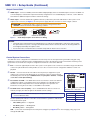
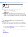
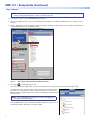
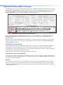
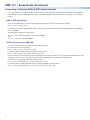
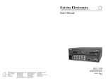
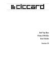
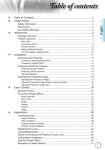
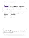
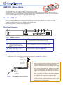
SMD 101 • Setup Guide
The Extron SMD 101 decodes video or graphics streams from an IP network,
plays back internal video and audio files, and plays Video On Demand files from network shares at their original resolution or
scaled up or down to any common SD, HD, or graphics resolution up to 1900x1200 (WUXGA). The SMD 101 can be deployed in
live event streaming and high level conferencing for specialized projects.
Mount the SMD 101
Before connecting the SMD 101, turn off all devices that will be connected to it. The SMD 101 is housed in a 1-inch high,
half‑rack width, 6‑inch deep metal enclosure that can sit on a table with the provided rubber feet or can be rack mounted. Select
a suitable mounting location, then choose an appropriate mounting option.
Make all external device connections before applying power.
Rear Panel Overview
1
2
Figure 1.
OUTPUTS
POWER
12V
1.0A MAX
4
3
L
AUDIO
R
HDMI
IR IN
S G
5
RS-232
6
7
RESET
Tx Rx G
LAN
SMD 101 Rear Panel
a 12 VDC Power input
e 3.5 mm, 3-pole captive screw connector for dual mode
b HDMI output
c 3.5 mm, 5-pole captive screw
f Reset button and LED
g RJ-45 Ethernet connector for connection to a LAN
d 3.5 mm, 3-pole captive screw
Front panel USB config port (see figure 4, e)
RS‑232 port (host control or IP pass-through)
connector for analog stereo audio
output
connector for wired IR receiver input
Power Supply Connection
a 12 VDC power input – Connect the provided 12 VDC power supply to the rear panel captive screw connector (see figure 2)
and plug in the power cord. Verify the front panel power LED lights (see figure 4, a on page 4).
Rear Panel
Power Receptacle
DC Power Cord
Captive Screw
Connector
AC Power Cord
Figure 2.
External
Power Supply
(12 VDC, 1 A )
External Power Supply Connection
POWER
12V
1.0A MAX
ATTENTION:
• Always use a power supply provided by or specified by Extron.
Use of an unauthorized power supply voids all regulatory
compliance certification and may cause damage to the supply
and the end product.
• Unless otherwise stated, the AC/DC adapters are not suitable
for use in air handling spaces or in wall cavities. The power
supply is to be located within the same vicinity as the Extron
AV processing equipment in an ordinary location, Pollution
Degree 2, secured to the equipment rack within the dedicated
closet, podium, or desk.
• The installation must always be in accordance with the
applicable provisions of National Electrical Code ANSI/NFPA
70, article 75 and the Canadian Electrical Code part 1, section
16. The power supply shall not be permanently fixed to
building structure or similar structure.
1
SMD 101 • Setup Guide (Continued)
Output Connections
b HDMI output – Connect an HDMI (or DVI with suitable adapter) display device to the HDMI output connector. The EDID of a
connected display is read and the output automatically configured. For non-standard displays or devices, see the SMD 101
User Guide for additional output resolutions and format settings.
c Audio output – Connect a balanced or unbalanced stereo (or dual mono) line level audio device to this 5-pole 3.5 mm
captive screw connector (see figure 1, c on the previous page). Wire the connector as shown in figure 3, below.
ATTENTION: For unbalanced audio, connect the sleeves to the ground contact.
DO NOT connect the sleeves to the negative (–) contacts.
Balanced Audio Output
Figure 3.
R
R
Tip
Sleeves
Tip
L
L
Tip
Ring
Sleeves
Tip
Ring
Do not tin the wires!
Unbalanced Audio Output
Audio Output Captive Screw Connector Wiring
NOTES:
• The length of the exposed wires in the stripping process is critical. The ideal length is 3/16 inch (5 mm). If longer,
the exposed wires may touch, causing a short circuit between them. If shorter, the wires can be easily pulled out
even if tightly fastened by the captive screws.
• Do not tin the wires. Tinned wire does not hold its shape and can become loose over time.
Control System Connections
The SMD 101 can be configured and controlled from the RS-232 port or the front panel mini-type B USB config port using
DataViewer, or from the LAN port using a standard web browser. Since the LAN port must be connected for streaming source
input, Extron recommends also using it for configuration and remote control of the SMD 101.
d IR In – Connect an (optional) IR receiver to this 3-pole 3.5 mm captive screw connector to extend the range of the IR hand
control. The optional IR hand control provides access to the on screen menus for configuration and direct control over
playback.
e RS-232 — Connect the host RS-232 cable to the rear panel (see right) with a 3-pole
IR IN
RS-232
S G
Tx Rx G
+ S G
IR
Transmitter
Receive
Transmit
Ground
captive screw connector for bi-directional (±5 V) serial host control or IP pass‑through.
The default protocol for this port is 9600 baud rate, no parity bit, 8 data bits, 1 stop bit,
and no flow control (handshaking).
RESET
LAN
f Reset button and LED — The SMD 101 has three reset modes to return user-defined
configuration settings or all settings back to factory defaults. The LED indicates the
desired reset mode, and provides the reset status during the reset operation. For
information on using the reset mode, see the SMD 101 User Guide.
g RJ-45 Ethernet connector (LAN) — Use a standard Ethernet cable to connect to a
network (see right). The table at right has the default network settings.
NOTE: To connect the SMD 101 directly to a computer Ethernet port, use a
crossover Ethernet cable.
The ACT (amber) LED indicator on the LAN connector blinks in a pattern to indicate the
connected network speed.
•
Three blinks, pause — 1 Gigahertz
•
Two blinks, pause — 100 Megahertz
•
One blink, pause — 10 Megahertz
Connected RS-232
Device Pins
IP Address: 192.168.254.254
Subnet Mask: 255.255.0.0
Default Gateway: 0.0.0.0
DHCP: OFF
USB — Connect the host USB port to the front panel config port (see figure 4, e on the next page), using a type A to
mini type B USB cable.
2
Front Panel Features
1
2
3
4
5
IR
CONFIG
SMD 101
Figure 4.
SMD 101 Front Panel
a Power LED – Lights solid green when the SMD 101 is powered. Lights solid red when in standby (low power) mode.
b Playback status indicator — Dual-color LED indicates the current state of playback operation:
•
Solid Green – The SMD 101 is actively decoding a stream.
•
Blinking Green – A stream is selected for decoding, but playback is paused.
•
Off – The selected stream is not being decoded.
•
Solid Red – Playback errors.
c Network status indicator — Dual-color LED indicates the current state of network operation and connection quality.
•
Solid Green – Indicates network conditions are favorable for the current source. The LED is also lit if the current source
is a local file.
•
Red/Green – When flashing red and green, indicates encoder or network conditions are compromising image or audio
quality, and the buffers could be depleted.
•
Solid Red – Indicates server or network conditions are compromising video or audio quality and the buffers could be
depleted.
•
Off – No network connectivity.
d IR Receiver Window— Allows remote operation using a compatible IR hand control (optional).
e Config port — Connect a control PC or other USB device to this port with a mini-type B USB cable (not supplied). Use this
port to send Simple Instruction Set (SIS™) commands to the SMD 101 for device configuration and control.
SMD 101 Configuration
The SMD 101 can be configured and controlled using a web‑browser. To configure the SMD 101 to play a multimedia stream:
1. Connect the external power supply to a 100 to 240 VAC, 50 or 60 Hz power source. The SMD 101 powers up and undergoes
a self testing sequence.
2. Power up all connected devices. The SMD 101 reads the EDID of the connected display device and sets the output
resolution and format.
3. The SMD 101 can be connected to a control PC using the front panel USB port, the rear panel RS-232 connection, or the
RJ‑45 LAN port (see Control System Connections on page 2). Ensure the control PC is on the same subnet, power the
PC, and open a web browser.
•
Google Chrome™ version 27 or higher (recommended),
•
Mozilla® Firefox® (version 15 or higher) or
•
Microsoft® Internet Explorer® version 8 or higher (for Windows operating systems).
4. Enter the default IP address of the SMD 101 (192.168.254.254) into the browser address bar and press <Enter> on the
keyboard.
The Player Page opens with the browser, lists, and playlist editor panels open. The browser Streams tab is selected (see
figure 5 on page 4).
5. Configure the SMD 101 using the Configuration, and Advanced Configuration pages. See the SMD 101 User Guide at
www.extron.com for details.
3
SMD 101 • Setup Guide (Continued)
Play a Stream:
NOTE: The SMD 101 must be connected to a LAN to locate and play streams. Clips or streams stored in internal
memory can be played without the need for a network connection.
1. In the Browser panel, select the Streams tab (see figure 5).
2. Click on an available stream to select it for decoding (see the SMD 101 User Guide for additional ways to specify or select
streams).
3. Click on and drag the stream from the Streams browser panel and drop it in the Player Controls panel. The URI for the
currently playing stream is in the Source: field.
1
3
√ Drop item into Player Control to load, or into Channels to add a new preset.
2
7HVW3DWWHUQ
4
4a
Figure 5.
4. Press play (
Player Page: Player Controls and Browser Panels
) to start playing the stream.
The source format and output format are shown near the bottom of the Player Controls panel (see figure 5, Ü).
To change the stream, repeat the above steps, selecting a new stream from the
streams list. The currently active stream stops playing and is removed from the
Source: field, then replaced by the new stream. Press Play to start playback of
the new stream.
Browser
Files
NOTE:Select Load Play under the player controls to start playback of
a selected source automatically.
Click the Files tab to access media files and clips stored in local memory or on
shared network drives and folders (see figure at right).
/
audio
Audio-File-1.m4a
clips
Video-clip-1.mp4
images
1920x1080-Image.jpg
nortxe-backup
shares
MediaShare
4
Operation With Extron SME 100 Encoders
For SME 100 stream discovery in the SMD 101 streams browser (see figure 5 on page 4), the SME 100 must have both
Stream Control and SAP Control enabled to enable SAP announcements. The SME 100 settings are shown below.
From the SME 100 default web page (see the SME 100 User Guide), select the Encoder Configuration link, then
Encoder Settings to open the configuration dialog shown in figure 6 below.
Streaming Configuration
Stream Control Stream Method
Enable
SAP Control
Enable
Figure 6.
Multi TS/RTP
Session Name
Test Pattern 1
Destination IP
Destination Port
238.13.197.190
Session Description Keywords
Bars and Tones
MTU
60000
1500
TTL
QoS (Differentiated Services)
10 Normal (CS3)
Author
test, pattern
Announce Frequency
Extron1
5 sec
SME 100 Encoder Configuration Panel (Partial View)
In both the Stream Control and SAP Control drop-down lists, select Enable. Choose a Destination IP and
Destination Port which avoid conflict with other multicast devices on your network, then enter them into the
appropriate fields.
With SAP Control enabled, the SME 100 stream (Test Pattern 1) is listed by the SMD 101 stream browser in the Extron
folder. To connect the stream, from the browser, drag and drop the stream anywhere on the Player Controls panel
(see Play a Stream: on page 4).
RTSP Multicast (Pull Streaming)
When using RTSP multicast from an SME 100, the SMD 101 must still connect to it using the SME 100 IP address (for
example rtsp://192.168.254.100) rather than the typical multicast IP address (for example rtsp://239.10.193.165).
If the SME 100 is set up for push streaming (Stream Control Enable), the RTSP bitrate is limited to 5 Mbps on startup or
restart. Although it can be higher, it is not recommended.
If higher bitrates are required, only a single stream method should be active.
Push Streaming (Unicast Port Numbers)
In systems with more than one SME 100 encoder using any of the unicast push methods (TS/UDP, TS/RTP, ES/RTP) to a
single SMD 101 decoder, each SME 100 must use a unique port number (such as 60000 and 61000). See the SMD 101
User Guide for additional information.
Multicast
For systems where streams from one or more SME 100s are received and decoded by multiple SMD 101s, multicast
addressing is strongly recommended. All network switches must be suitably rated and correctly configured for IGMP
snooping and multicast filtering with an active IGMP querier (possibly the network switch) available on the local subnet
for optimum performance.
5
SMD 101 • Setup Guide (Continued)
Connecting to Streams Without SAP Announcements
For a source that is not configured for SAP announcements (such as IP cameras), the RTSP (pull) stream URI is entered directly
in the Source: field of the SMD 101 player controls. The URI prefix (udp in the example below) corresponds to the streaming
method.
UDP or RTP Connections
To connect the SMD 101 to a stream using the destination port of the encoder, use the following template:
udp://@:<destination port>
For example, to connect to the SME 100 stream in figure 6, enter the following URI in the SMD 101 Source field (see figure 5):
udp://@:60000
The SMD 101 also supports the URI formats:
ts/rtp://[email protected]:60000
and
ts/rtp://@192.168.254.254:60000
HTTP Connection to an SME 100
To connect to RTSP streams over HTTP, use the following templates.
For unicast streams, the URI format is:
http://<sme_ip_adr>/web/output1.sdp.
For multicast RTP over UDP RTSP (pull) streams, the URI format is:
http://<sme_ip_adr>/web/output1/multicast.sdp.
If the encoder has an active admin password, it challenges the connection. An admin or user password is required for connection.
To play the stream, the user name and password must be embedded in the URI entered in the Source field.
For unicast streams requiring credentials, the URI format is:
http://user:password@<sme_ip_adr>/web/output1.sdp.
For multicast RTP over UDP RTSP (pull) streams requiring credentials, the URI format is:
http://user:password@<sme_ip_adr>/web/output1/multicast.sdp.
6
Play Video on Demand
The SMD 101 can play video on demand from network shares and supports the following file types:
Video: [mp4,ts,m2t,m2ts,mov*,264,m4v,flv*,sdp]
NOTE: *Supports files that use H.264 encoding and AAC audio only.
Images: [bmp,jpg,jpeg,tif,tiff,png,gif],
NOTE: TIFF files using JPEG compression are not supported.
Audio: [wav,aac,m4a]
Playlists: [jspf, m3u, m3u8, pls, and xspf].
The shared folder must be added to the player browser file list. To add a shared folder:
1. From the Files browser (click the Files tab in the browser panel), click Network Shares.
Network - Shares
Network Path:
\\192.168.127.101\SharedFolder
User Name:
Password:
Options:
Local Name: MediaShare
Reconnect at power up:
Save
Cancel
Network Shares
Figure 9.
Network Share Configuration
2. In the Network Path: field, enter the full path of the shared folder using the IP address or host name of the server.
3. Enter a user name and password in the next fields, if assigned.
4. Enter a local name for the shared folder.
NOTE: A local name for the shared folder (in this example, MediaShare) is
optional. If the user does not define a name, it defaults to the server folder name
(SharedFolder in figure 9).
5. Click Save.
The SMD 101 connects to the shared folder and installs it under the default Shares folder of the files browser.
images
MediaShare
Figure 10. Browser Shares Folder
To play a file shared on the network share, from the browser files tab, drag the selected file in the Shares folder and drop it in
the player panel (see figure 5 on page 4).
7
Play Local Content
Browser
The SMD 101 has internal memory reserved for local content. Local content is viewed
from the browser Files tab. A typical folder structure for the internal memory is
shown at right.
Files
/
NOTES:
audio
• The media folder is currently reserved for future use. Do not put user
content files in the folder.
Audio-File-1.m4a
clips
Video-clip-1.mp4
images
• TMP folders are not accessible.
1920x1080-Image.jpg
nortxe-backup
Content (up to 175 MB total) can be transferred directly to the SMD 101 from a
computer on the same network using an FTP client such as Filezilla, a free FTP
program available here:
shares
MediaShare
https://filezilla-project.org/download.php?type=client
Download and install the FileZilla program.
After installation, run the program.
1. From the toolbar select File>Site Manager. The Site Manager dialog
opens (see right).
2. Enter the SMD 101 IP address in the Host: field.
General
Host:
192.168.193.165
Protocol:
SFTP-SSH File Transfer Protocol
Port: 22022
3. Enter 22022 in the Port: field.
4. Select SFTP in the Protocol: drop-down list.
Logon Type: Normal
5. Select Normal from the Logon Type: drop-down list.
6. Enter admin in the User: field.
7. Enter the SMD 101 admin password if one is set. Otherwise leave the
Password: field blank.
User:
admin
Password:
*****
Account:
8. Click Connect to start the connection routine.
Filezilla establishes a connection with the SMD 101 at the IP address in the
Host: address and logs in.
Comments:
Filezilla defaults to the root of the SMD 101 local memory (on the right in the figure
below) and shows all files and folders stored in the user file system.
In the example below, a file is uploaded from the PC to the SMD 101 Clips folder
using the right-click menu.
Local site: C:\Users\Videos\MediaShare
Remote site:
PC file uploads to:
PC Folders and Files
Extron Headquarters
+800.633.9876 Inside USA/Canada Only
Extron USA - West
Extron USA - East
+1.714.491.1500+1.919.850.1000
+1.714.491.1517 FAX
+1.919.850.1001 FAX
SMD 101 Folders and Files
Extron Europe
+800.3987.6673
Inside Europe Only
+31.33.453.4040
+31.33.453.4050 FAX
Extron Asia
+65.6383.4400
+65.6383.4664 FAX
Extron Japan
+81.3.3511.7655
+81.3.3511.7656 FAX
Extron China
+86.21.3760.1568
+86.21.3760.1566 FAX
Extron Middle East
+971.4.299.1800
+971.4.299.1880 FAX
Extron Korea
+82.2.3444.1571
+82.2.3444.1575 FAX
Extron India
1800.3070.3777
(Inside India Only)
+91.80.3055.3777
+91.80.3055.3737 FAX
© 2014 Extron Electronics All rights reserved. All trademarks mentioned are the property of their respective owners. www.extron.com
8
68-2231-50 Rev. A
02 14