1
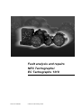
Fault analysis and repairs
NEC Tachographs/
EC Tachographs 1318
TU00-1318-0200302
© Siemens VDO Trading GmbH
Any changes will be notified by service information or circular.
This documentation is protected by copyright law for Siemens VDO Trading
GmbH and must not be reproduced without prior written consent by Trading
GmbH or used against the due interest of Trading GmbH. It is exclusively for
internal use for service work. Any other use is not permitted. Any
communication of this documentation to a third party requires the prior express
written permission of Siemens VDO Trading GmbH.
We reserve the right to change technical details of the descriptions, information
and illustrations in this documentation.
Printed in Federal Republic of Germany.
Responsible for the content
Siemens VDO Trading GmbH
Postfach 16 40
D - 78052 Villingen-Schwenningen
Orders
Please send your orders to the your representative.
2
© Siemens VDO Trading GmbH
TU00-1318-0200302
Technical Product Manual
Fault analysis and repairs 1318
Table of contents
Table of contents
Table of contents • Edition 12/2005
Section 1 General notes
1
Contents ...................................................................................................1-2
1
General notes...........................................................................................1-3
1.1
History - 1318 ...........................................................................................1-3
1.2
Preparing repairs......................................................................................1-3
1.3
Repair hints ..............................................................................................1-4
1.4
Workbench setup .....................................................................................1-5
1.5
Auxiliary tools – detailed view ..................................................................1-6
Section 2 Removing and fitting housing cover
2
Contents and assignment.........................................................................2-2
2.1
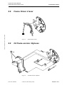
Housing cover – overall view....................................................................2-7
2.2
Type plaque labelling ...............................................................................2-8
2.3
Removing front parts ................................................................................2-9
2.3.1
Removing bezel........................................................................................2-9
2.3.2
Replacing dial glass ...............................................................................2-10
2.3.3
Lock cylinder ..........................................................................................2-11
2.3.4
Replacing driver and lock bolt ................................................................2-12
2.4
Modified cover and dial support (from 07.98).........................................2-13
2.5
Removing indicators and dial components.............................................2-14
2.5.1
Speed indicator ......................................................................................2-14
2.5.2
RPM indicator.........................................................................................2-14
2.5.3
Clock hands ...........................................................................................2-15
2.5.4
Disengaging stop springs .......................................................................2-15
2.5.5
Removing and replacing dial elements ..................................................2-16
2.5.6
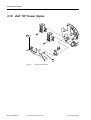
1318 with MOTOMETER dial .................................................................2-17
2.6
Removing cover plate/lamp plate ...........................................................2-18
2.6.1
Removing gears from n measuring system............................................2-18
2.6.2
Unsoldering wires, contact spring and coil .............................................2-18
TU00-1318-0200302
© Siemens VDO Trading GmbH
1
Table of contents
2
2.6.3
Removing cover plate/lamp plate .......................................................... 2-19
2.7
Flat cable ............................................................................................... 2-20
2.7.1
Flat cable versions for KTCO 1318........................................................ 2-20
2.7.2
Fitting flat cable...................................................................................... 2-21
2.7.3
Measuring adapter for new flat cable (from 08.00) ................................ 2-22
2.7.4
Replacing light emitting diode................................................................ 2-23
2.8
n measuring system............................................................................... 2-24
2.8.1
Removing n measuring system ............................................................. 2-24
2.8.2
Removing stylus lever............................................................................ 2-24
2.8.3
Replacing gears..................................................................................... 2-24
2.8.4
Removing contact springs with holder on n measuring system ............. 2-25
2.8.5
Fitting contact spring and holder............................................................ 2-26
2.8.6
Checking integral potentiometer ............................................................ 2-27
2.8.7
Checking DC motor ............................................................................... 2-28
2.8.8
Removing and installing DC motor ........................................................ 2-28
2.8.9
Modified n frame (from 02.00) ............................................................... 2-29
2.9
Quartz mechanism................................................................................. 2-30
2.9.1
Checking fibre glass quartz mechanism ................................................ 2-30
2.9.2
Removing fibre glass quartz mechanism............................................... 2-31
2.9.3
Replacing gears..................................................................................... 2-31
2.9.4
Modified quartz mechanism ................................................................... 2-32
2.9.5
Speed shaft............................................................................................ 2-35
2.10
Cover contact......................................................................................... 2-36
2.10.1
Replacing cover contact ........................................................................ 2-36
2.10.2
Checking cover contact ......................................................................... 2-37
2.11
Fitting quartz mechanism, n measuring system, lamp plate and cover plate
2-38
2.11.1
Fitting quartz mechanism....................................................................... 2-39
2.11.2
Fitting n measuring system.................................................................... 2-39
2.11.3
Fitting n stylus lever ............................................................................... 2-40
2.11.4
Fitting cover plate and lamp plate.......................................................... 2-41
2.11.5
Clockwork mechanism malfunction ....................................................... 2-42
2.11.6
Making electrical connections................................................................ 2-43
2.11.7
n measuring system - Inserting spur gears............................................ 2-44
2.12
Fitting dial components and indicators .................................................. 2-45
© Siemens VDO Trading GmbH
TU00-1318-0200302
Table of contents • Edition 12/2005
Technical Product Manual
Fault analysis and repairs 1318
Table of contents
2.12.1
Fitting dial components ..........................................................................2-45
2.12.2
Making auxiliary bezel ............................................................................2-46
2.12.3
Fitting n and v indicators ........................................................................2-47
2.12.4
Checking indicator running.....................................................................2-47
2.12.5
Checking engagement depth .................................................................2-48
2.12.6
Fitting clock hands..................................................................................2-49
2.12.7
Modified hands for IVECO version. ........................................................2-50
2.12.8
Fitting bezel ............................................................................................2-50
2.13
Removing cover plate and knobs ...........................................................2-51
2.13.1
Removing cover plate.............................................................................2-51
2.13.2
Pulling out knobs ....................................................................................2-52
2.14
Distance recorder ...................................................................................2-53
2.14.1
Setting counter .......................................................................................2-53
2.14.2
Removing distance counter....................................................................2-54
2.14.3
Fitting distance counter ..........................................................................2-55
2.15
Fitting cover plate and knobs .................................................................2-56
2.15.1
Fitting knobs ...........................................................................................2-56
2.15.2
Cover plate versions...............................................................................2-58
2.15.3
Fitting cover plate ...................................................................................2-60
2.16
Fitting stylus guide/7-day cutting blade ..................................................2-61
2.16.1
Fitting stylus guide..................................................................................2-61
2.16.2
Fitting 7-day cutting blade ......................................................................2-61
2.16.3
Modified cutting blade (from 05.99)........................................................2-62
2.17
Replacing separating plate and cover ....................................................2-64
2.17.1
Replacing plate on defective covers.......................................................2-64
2.17.2
Replacing defective separating plate .....................................................2-64
2.17.3
Separating plate .....................................................................................2-65
2.17.4
Secure contact with 318 warning LED (from 05.97)...............................2-65
2.18
Replacing cover and cover strap............................................................2-66
2.18.1
Replacing cover......................................................................................2-66
2.18.2
Modified cover dimensions (from 01.96) ................................................2-67
2.18.3
Replacing cover strap.............................................................................2-68
Section 3 Removing and fitting housing
TU00-1318-0200302
© Siemens VDO Trading GmbH
3
Table of contents
4
3
Contents and assignment ........................................................................ 3-2
3.1
Housing – overall view............................................................................. 3-9
3.2
Removing hood...................................................................................... 3-10
3.2.1
Inserting removal tool ............................................................................ 3-10
3.2.2
Fixing cap versions ................................................................................ 3-10
3.2.3
Removing fixing cap .............................................................................. 3-11
3.2.4
Removing hood...................................................................................... 3-11
3.3
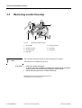
Removing socket housing...................................................................... 3-12
3.4
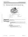
Removing trough connector/ plug unit / lug ........................................... 3-13
3.5
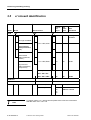
v/ n board identification.......................................................................... 3-14
3.6
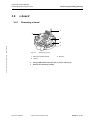
v board................................................................................................... 3-15
3.6.1
Removing v board.................................................................................. 3-15
3.6.2
Replacing v board coding plate ............................................................. 3-16
3.6.3
Series v board converted into a service version (until 10.91) ................ 3-17
3.6.4
Converting v board for 140 km/h (up to approx. 03.91) ......................... 3-17
3.6.5
Converting series v board into service version (until 03.93) .................. 3-18
3.6.6
Converting a series v board into a service version (until 10.94) ............ 3-20
3.6.7
Converting a series µP v board into a service version (from 11.94) ...... 3-21
3.7
n board................................................................................................... 3-22
3.7.1
Removing n board ................................................................................. 3-22
3.7.2
Converting series n board into a service version ................................... 3-23
3.7.3
Converting a series µP v board into a service version (from 11.94) ...... 3-24
3.8
Removing frame .................................................................................... 3-26
3.8.1
Removing frame completely .................................................................. 3-26
3.8.2
Removing v contact carrier .................................................................... 3-27
3.8.3
Removing stylus unit.............................................................................. 3-28
3.8.4
Fitting on 2 driver unit ............................................................................ 3-30
3.8.5
Removing and installing gears............................................................... 3-32
3.8.6
Fitting stop, spur gear and stop spring for driver 1 ................................ 3-35
3.9
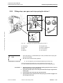
Installing/ removing CH time group recording........................................ 3-36
3.9.1
Removing drive parts ............................................................................. 3-37
3.9.2
Fitting stylus holder................................................................................ 3-37
3.9.3
Fitting switching and drive parts ............................................................ 3-37
3.9.4
Fitting/ adjusting driver 1 drive parts ...................................................... 3-38
3.9.5
Fitting on 2 driver unit ............................................................................ 3-39
© Siemens VDO Trading GmbH
TU00-1318-0200302
Table of contents • Edition 12/2005
Technical Product Manual
Fault analysis and repairs 1318
Table of contents
3.10
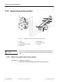
Speed measuring system.......................................................................3-42
3.10.1
Removing speed measuring system ......................................................3-42
3.10.2
Checking and replacing speed measurement system............................3-43
3.10.3
Checking and replacing motor................................................................3-44
3.10.4
Removing and fitting socket housing contacts .......................................3-46
3.10.5
Speed measuring system.......................................................................3-47
3.11
Distance/ WT motor................................................................................3-48
3.11.1
Removing distance or WT motor............................................................3-48
3.11.2
Checking the distance/ WT motor ..........................................................3-48
3.11.3
Replacing and installing distance or WT motor when faulty...................3-49
3.11.4
Preparing frame plate (version till 09.87) for installing
distance/ WT motor (version from 10.87) ...............................................3-49
3.12
Replacing contact set for warning device (up to 04.90) .........................3-50
3.12.1
Modified contact set for warning device (up to 10.91)............................3-52
3.12.2
Modified contact set for warning device (up to 07.93)............................3-53
3.12.3
Modified contact set for warning device (up to 04.94)............................3-54
3.12.4
Modified contact set for warning device (from 05.94).............................3-55
3.13
Replacing carriage contact.....................................................................3-56
3.14
Fitting frame plate...................................................................................3-57
3.14.1
Installing stylus unit and making sure it engages ...................................3-57
3.14.2
Fitting the tension spring/ v contact carrier/ wires ..................................3-59
3.15
Replacing grip head, jack socket and test socket on housing................3-61
3.15.1
Replacing grip head ...............................................................................3-62
3.15.2
Replacing jack socket for speed.............................................................3-62
3.15.3
Replacing rpm test socket ......................................................................3-62
3.16
Completing back of housing ...................................................................3-63
3.16.1
Fitting the frame .....................................................................................3-63
3.16.2
Adjusting the contact set for warning device ..........................................3-64
3.16.3
Default setting for driver 2 coupling........................................................3-65
3.16.4
Fitting n board ........................................................................................3-66
3.16.5
Fitting v board ........................................................................................3-67
3.16.6
Laying cables, making electrical connections ........................................3-70
3.16.7
fixing v and n boards ..............................................................................3-70
3.16.8
Fitting the lug holder and lug ..................................................................3-71
3.16.9
Plug unit and trough connector ..............................................................3-73
TU00-1318-0200302
© Siemens VDO Trading GmbH
5
Table of contents
3.17
Data output – data block........................................................................ 3-76
Section 4 Checking and adjusting
4
Contents and assignment ........................................................................ 4-2
4.1
Adjustment tool for styluses and coupling levers (from 01.02) ................ 4-3
4.2
Checking and correcting position of speed recording.............................. 4-4
4.2.1
Checking speed stylus ............................................................................. 4-4
4.2.2
Correcting speed recording ..................................................................... 4-5
4.2.3
Checking and adjusting speed recording for speed dial .......................... 4-6
4.3
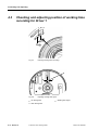
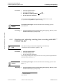
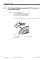
Checking and adjusting position of working time recording for Driver 1 .. 4-8
4.3.1
Checking and adjusting working time recording with NEC ** 1318-02, -04, 06............................................................................................................. 4-9
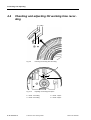
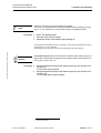
4.4
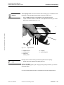
Checking and adjusting CH working time recording .............................. 4-10
4.5
Checking and correcting position of distance recording ........................ 4-12
4.6
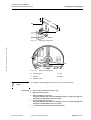
Checking and adjusting position of Driver 2 working time recording ..... 4-14
4.7
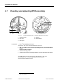
Checking and adjusting RPM recording ................................................ 4-18
4.8
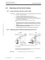
Adjusting unit test bench display ........................................................... 4-21
4.8.1
Speed calibration adjustment (km/h, mph) ............................................ 4-21
4.8.2
Modifying speed calibration adjustment (from 07.98) ............................ 4-21
4.9
Adjusting unit to test bench display ....................................................... 4-22
4.9.1
Speed calibration adjustment (km/h, mph) ............................................ 4-23
4.9.2
RPM calibration adjustment (1/min, rev/min)......................................... 4-23
4.10
Function check....................................................................................... 4-24
Section 5 Sealing points
6
5
Contents and assignment ........................................................................ 5-2
5.1
Sealing points and protective elements ................................................... 5-3
5.2
Removing seal caps, bezel seal and fixing caps ..................................... 5-4
5.3
Fixing cap versions .................................................................................. 5-4
5.4
Fitting seals and fixing caps..................................................................... 5-5
5.4.1
Embossing seals...................................................................................... 5-5
5.4.2
Fitting seal caps....................................................................................... 5-6
5.4.3
Fitting bezel seal...................................................................................... 5-6
5.4.4
Fitting hood fixing caps ............................................................................ 5-7
© Siemens VDO Trading GmbH
TU00-1318-0200302
Technical Product Manual
Fault analysis and repairs 1318
Table of contents
Table of contents • Edition 12/2005
Section 6 Additional equipment
6
Contents and assignment.........................................................................6-2
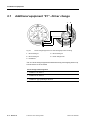
6.1
Additional equipment "01" - Driver change...............................................6-4
6.1.1
Recording widths......................................................................................6-5
6.1.2
Repair hint ................................................................................................6-5
6.1.3
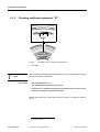
Checking additional equipment "01".........................................................6-6
6.2
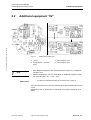
Additional equipment "04" ........................................................................6-7
6.3
Additional equipment "09" ........................................................................6-8
6.3.1
External speed warning contact (connector A8).......................................6-8
6.3.2
Adjusting "v" warning value ......................................................................6-9
6.3.3
Pulse output 4 imp/m (connector B8) .....................................................6-10
6.3.4
Checking pulse output 4 imp/m ..............................................................6-10
6.3.5
Stop signal (connector D8).....................................................................6-11
6.3.6
Checking stop signal ..............................................................................6-11
6.4
Additional equipment "45" – Two-level additional stylus (connectors D1 / D2)
6-12
6.4.1
Function .................................................................................................6-12
6.4.2
Control....................................................................................................6-13
6.4.3
Adjusting additional stylus ......................................................................6-13
6.4.4
Checking recording ................................................................................6-14
6.4.5
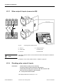
Retrofitting additional stylus ...................................................................6-15
6.4.6
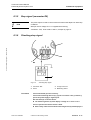
Clock generator 2154.02 ........................................................................6-17
6.4.7
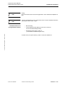
1318 with additional equipment "45" - Clock generator and pulse memory620
6.5
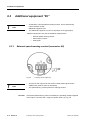
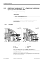
Additional equipment "70" – RPM unit without RPM display..................6-21
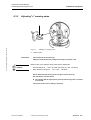
6.5.1
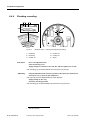
Adjusting ................................................................................................6-22
6.5.2
RPM constant label ................................................................................6-22
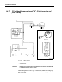
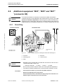
6.6
Additional equipment "B03", "B05" and "B07" *(connector D5)..............6-23
6.6.1
Retrofitting ..............................................................................................6-23
6.6.2
Checking two speed axle adjustment.....................................................6-24
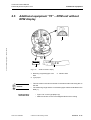
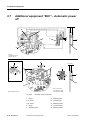
6.7
Additional equipment "B30" – Automatic power off ................................6-26
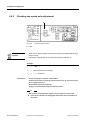
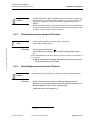
6.7.1
Checking automatic power-off function ..................................................6-27
6.7.2
Retrofitting automatic power-off board ...................................................6-27
TU00-1318-0200302
© Siemens VDO Trading GmbH
7
Table of contents
Section 7 Wiring diagrams, fault analysis
7
Contents and unit assignment ................................................................. 7-2
7.1
Connector assignment and connections "A, B, C, D" .............................. 7-3
7.2
Colour codes............................................................................................ 7-3
7.3
Additional equipment "A" and "B" – Type summary / combinations ........ 7-4
7.4
Fault analysis workflow sample ............................................................... 7-5
7.5
"Basic" wiring diagram and fault analysis ............................................... 7-6
7.6
Wiring diagram and "RPM" fault analysis ................................................ 7-8
7.7
"Basic" wiring diagram and fault analysis - µP v board.......................... 7-10
7.8
"RPM" wiring diagram and fault analysis - µP n board .......................... 7-12
7.9
"EC units" and "CH" wiring diagram and fault analysis.......................... 7-14
7.10
Additional equipment "A" and "B" wiring diagram and fault analysis ..... 7-16
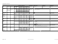
Section 8 Lubrication charts
8
8
Contents and unit assignment ................................................................. 8-2
8.1
Lubricants list – Greases and oils ............................................................ 8-3
8.2
Distance counter...................................................................................... 8-5
8.3
n frame: Studs, sockets, styluses ............................................................ 8-5
8.4
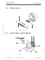
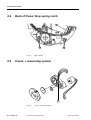
Back of frame: Stop spring catch............................................................. 8-6
8.5
Frame: v measuring system .................................................................... 8-6
8.6
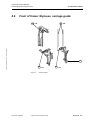
Front of frame: Styluses, carriage guide.................................................. 8-7
8.7
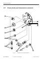
Frame studs and transmission elements ................................................. 8-8
8.8
Frame: Driver 2 lever ............................................................................... 8-9
8.9
CH frame version: Styluses ..................................................................... 8-9
8.10
ZuE "45" frame: Stylus........................................................................... 8-10
© Siemens VDO Trading GmbH
TU00-1318-0200302
Technical Product Manual
Fault analysis and repairs 1318
List of illustrations
List of illustrations • Edition 12/2005
List of illustrations
Fig. 1-1
Workbench design....................................................................................1-5
Fig. 1-2
Auxiliary tools ...........................................................................................1-6
Fig. 2-1
Housing cover – overall view....................................................................2-7
Fig. 2-2
Type plaque labelling ...............................................................................2-8
Fig. 2-3
Removing bezel seals ..............................................................................2-9
Fig. 2-4
Replacing dial glass ...............................................................................2-10
Fig. 2-5
Removing lock cylinder ..........................................................................2-11
Fig. 2-6
Fitting lock cylinder.................................................................................2-11
Fig. 2-7
Replacing driver and lock bolt ................................................................2-12
Fig. 2-8
Cover with modified stop bolts and correct dial support.........................2-13
Fig. 2-9
Removing indicators...............................................................................2-14
Fig. 2-10
Disengaging stop springs .......................................................................2-15
Fig. 2-11
Removing and replacing dial elements ..................................................2-16
Fig. 2-12
MOTOMETER dial .................................................................................2-17
Fig. 2-13
Housing cover without dial elements (RPM units)..................................2-18
Fig. 2-14
Removing cover plate/lamp plate ...........................................................2-19
Fig. 2-15
Flat cable versions .................................................................................2-20
Fig. 2-16
Fitting flat cable ......................................................................................2-21
Fig. 2-17
Measuring adapter for new flat cable (from 08.00).................................2-22
Fig. 2-18
Replacing light emitting diode ................................................................2-23
Fig. 2-19
Removing n measuring system ..............................................................2-24
Fig. 2-20
Removing contact springs on n measuring system................................2-25
Fig. 2-21
Fitting contact spring and holder ............................................................2-26
Fig. 2-22
Checking potentiometer .........................................................................2-27
Fig. 2-23
Checking, removing and installing DC motor .........................................2-28
Fig. 2-24
Modified n frame (from 02.00) ................................................................2-29
Fig. 2-25
Checking quartz mechanism ..................................................................2-30
Fig. 2-26
Replacing gears .....................................................................................2-31
Fig. 2-27
Fibre glass quartz mechanism (from 11.96)...........................................2-32
Fig. 2-28
Bridge with guide on mechanism ...........................................................2-33
Fig. 2-29
Clockwork mechanism made of transparent plastic ...............................2-34
Fig. 2-30
Speed shaft ............................................................................................2-35
Fig. 2-31
Removing cover contact.........................................................................2-36
TU00-1318-0200302
© Siemens VDO Trading GmbH
1
List of illustrations
Fig. 2-32
Riveting cover contact ........................................................................... 2-36
Fig. 2-33
Checking cover contact ......................................................................... 2-37
Fig. 2-34
Fitting quartz mechanism and n measuring system .............................. 2-38
Fig. 2-35
Fitting n stylus lever ............................................................................... 2-40
Fig. 2-36
Fitting cover plate and lamp plate (n measuring system not shown)..... 2-41
Fig. 2-37
Modified cover plate with rotor cover ..................................................... 2-42
Fig. 2-38
Cover plate/lamp plate – making electrical connections........................ 2-43
Fig. 2-39
Inserting spur gears ............................................................................... 2-44
Fig. 2-40
Fitting dial components.......................................................................... 2-45
Fig. 2-41
Making auxiliary bezel ........................................................................... 2-46
Fig. 2-42
Fitting indicators / pressing on v indicator.............................................. 2-47
Fig. 2-43
Checking engagement depth................................................................. 2-48
Fig. 2-44
Inserting adjustment disc / fitting clock hands ....................................... 2-49
Fig. 2-45
Fitting bezel ........................................................................................... 2-50
Fig. 2-46
Removing cover plate ............................................................................ 2-51
Fig. 2-47
Removing knobs .................................................................................... 2-52
Fig. 2-48
Setting counter....................................................................................... 2-53
Fig. 2-49
Removing distance counter ................................................................... 2-54
Fig. 2-50
Modified knobs....................................................................................... 2-56
Fig. 2-51
Inserting knobs ...................................................................................... 2-57
Fig. 2-52
Cover plate versions .............................................................................. 2-58
Fig. 2-53
Inserting cover plate .............................................................................. 2-60
Fig. 2-54
Fitted cover plate ................................................................................... 2-60
Fig. 2-55
Fitting stylus guide/7-day cutting blade.................................................. 2-61
Fig. 2-56
Cutting blade (from 05.99) ..................................................................... 2-62
Fig. 2-57
Replacing separating plate .................................................................... 2-64
Fig. 2-58
Secure contact with 318 warning LED (from 05.97) .............................. 2-65
Fig. 2-59
Removing cover strap............................................................................ 2-66
Fig. 2-60
Cover housing........................................................................................ 2-66
Fig. 2-61
Modified cover unit dimensions ............................................................. 2-67
Fig. 2-62
Fastening cover strap to housing........................................................... 2-68
Fig. 2-63
Cover strap version................................................................................ 2-68
Fig. 3-1
Housing – overall view............................................................................. 3-9
Fig. 3-2
Inserting removal tool ............................................................................ 3-10
Fig. 3-3
Fixing cap versions ................................................................................ 3-10
2
© Siemens VDO Trading GmbH
TU00-1318-0200302
List of illustrations • Edition 12/2005
Technical Product Manual
Fault analysis and repairs 1318
List of illustrations
Fig. 3-4
Removing fixing cap ...............................................................................3-11
Fig. 3-5
Removing hood ......................................................................................3-11
Fig. 3-6
Removing socket housing ......................................................................3-12
Fig. 3-7
Removing trough connector, lug, plug units ...........................................3-13
Fig. 3-8
Removing v board ..................................................................................3-15
Fig. 3-9
Replacing coding plate ...........................................................................3-16
Fig. 3-10
Series v board converted into a service version (until 10.91).................3-17
Fig. 3-11
Converting series v board into service version (until 03.93)...................3-18
Fig. 3-12
Converting a series v board into a service version (until 10.94).............3-20
Fig. 3-13
Converting a series µP v board into a service version (from 11.94) ......3-21
Fig. 3-14
Removing n board ..................................................................................3-22
Fig. 3-15
Converting standardn board to service version......................................3-23
Fig. 3-16
Converting series µP n board into a service version ..............................3-24
Fig. 3-17
Removing frame completely...................................................................3-26
Fig. 3-18
Contact carrier........................................................................................3-27
Fig. 3-19
Removing stylus unit ..............................................................................3-28
Fig. 3-20
Distance stylus (from 02.00)...................................................................3-29
Fig. 3-21
v, distance and WT carriages (from 04.97) ............................................3-29
Fig. 3-22
Fitting/ removing drive parts for driver 2.................................................3-30
Fig. 3-23
Fitting connecting link, spur gear and stop spring ..................................3-31
Fig. 3-24
Removing and installing gears (unit type 1318 – 26,–27) ......................3-32
Fig. 3-25
Fitting stop, spur gear and stop spring for driver 1.................................3-35
Fig. 3-26
CH drive parts assembled and dismantled.............................................3-36
Fig. 3-27
Gear lever/ spur gear (CH).....................................................................3-38
Fig. 3-28
Driver 2 drive parts .................................................................................3-39
Fig. 3-29
Replacing lever.......................................................................................3-40
Fig. 3-30
Removing and checking speed measurement system...........................3-42
Fig. 3-31
Checking and replacing motor................................................................3-44
Fig. 3-32
Removing and fitting socket housing contact .........................................3-46
Fig. 3-33
Installing speed measuring system ........................................................3-47
Fig. 3-34
Removing, installing and checking distance and WT motor...................3-48
Fig. 3-35
Frame with three flange centring bars....................................................3-49
Fig. 3-36
Replacing contact set for warning device (up to 04.90) .........................3-50
Fig. 3-37
Replacing contact set (up to 10.91)........................................................3-52
Fig. 3-38
Modified contact set for warning device (up to 07.93)............................3-53
TU00-1318-0200302
© Siemens VDO Trading GmbH
3
List of illustrations
Fig. 3-39
Modified contact set for warning device (up to 04.94) ........................... 3-54
Fig. 3-40
Modified contact set for warning device (from 05.94) ............................ 3-55
Fig. 3-41
Replacing carriage contact .................................................................... 3-56
Fig. 3-42
Fitting stylus unit .................................................................................... 3-57
Fig. 3-43
Complete front and back of frame plate................................................. 3-59
Fig. 3-44
Replacing grip head, jack socket and test socket.................................. 3-61
Fig. 3-45
Installing frame ...................................................................................... 3-63
Fig. 3-46
Adjusting the contact set for warning device ........................................ 3-64
Fig. 3-47
Default setting for driver 2 coupling ....................................................... 3-65
Fig. 3-48
Fitting n board onto back of housing...................................................... 3-66
Fig. 3-49
Fitting v board to back of housing.......................................................... 3-67
Fig. 3-50
Fitting v board Detailed view of frame plate........................................... 3-68
Fig. 3-51
2 driver EC v board in 1 driver unit ........................................................ 3-69
Fig. 3-52
Laying cables, making electrical connections........................................ 3-70
Fig. 3-53
Fitting lug for warning device ................................................................. 3-71
Fig. 3-54
Fitting lug holder for warning device ...................................................... 3-71
Fig. 3-55
Putting lug onto lug holder ..................................................................... 3-72
Fig. 3-56
Fitting plug unit and trough connector ................................................... 3-73
Fig. 3-57
Hood with integral trough connector from 02.04.................................... 3-74
Fig. 3-58
Hood modification (from 03.99) ............................................................. 3-75
Fig. 3-59
Data output and optical fibre.................................................................. 3-76
Fig. 4-1
Adjustment tool ........................................................................................ 4-3
Fig. 4-2
Inserting adjustment disc ......................................................................... 4-4
Fig. 4-3
Checking speed recording ....................................................................... 4-5
Fig. 4-4
Adjusting speed stylus ............................................................................. 4-5
Fig. 4-5
Checking speed dial for speed recording ................................................ 4-6
Fig. 4-6
Checking speed recording ....................................................................... 4-6
Fig. 4-7
Checking working time recording............................................................. 4-8
Fig. 4-8
Adjusting working time stylus................................................................... 4-8
Fig. 4-9
Checking CH working time recording .................................................... 4-10
Fig. 4-10
Adjusting CH working time stylus .......................................................... 4-10
Fig. 4-11
Checking distance stylus recording ....................................................... 4-12
Fig. 4-12
Adjusting distance stylus ....................................................................... 4-12
Fig. 4-13
Checking Driver 2 recording .................................................................. 4-14
Fig. 4-14
Adjustment tool ...................................................................................... 4-15
4
© Siemens VDO Trading GmbH
TU00-1318-0200302
List of illustrations • Edition 12/2005
Technical Product Manual
Fault analysis and repairs 1318
List of illustrations
Fig. 4-15
Adjusting coupling lever .........................................................................4-17
Fig. 4-16
Adjusting coupling lever .........................................................................4-17
Fig. 4-17
Inserting adjustment disc / Checking RPM dial for recording.................4-18
Fig. 4-18
Checking RPM recording .......................................................................4-19
Fig. 4-19
Modifying the speed calibration adjustment (from 07.98).......................4-21
Fig. 4-20
Speed / RPM calibration adjustment ......................................................4-22
Fig. 5-1
Sealing points and protective elements on the unit..................................5-3
Fig. 5-2
Fixing caps on hood .................................................................................5-3
Fig. 5-3
Fixing cap versions...................................................................................5-4
Fig. 5-4
Embossing seals ......................................................................................5-5
Fig. 5-5
Fitting seal cap and bezel seal .................................................................5-6
Fig. 5-6
Fitting hood and fixing caps......................................................................5-7
Fig. 6-1
Driver change equipment "01" with tachograph chart recording ..............6-4
Fig. 6-2
v board service version ............................................................................6-5
Fig. 6-3
Bar width position – Additional equipment "01"........................................6-6
Fig. 6-4
Additional equipment "04" ........................................................................6-7
Fig. 6-5
v warning value/ output A8 .......................................................................6-8
Fig. 6-6
Adjusting "v" warning value ......................................................................6-9
Fig. 6-7
Checking pulse output 4 imp/m ..............................................................6-10
Fig. 6-8
Checking stop signal ..............................................................................6-11
Fig. 6-9
Deflection – Level 1 / Level 2 .................................................................6-12
Fig. 6-10
Setting drive parts ..................................................................................6-13
Fig. 6-11
Additional stylus - Checking and adjusting recording.............................6-14
Fig. 6-12
Retrofitting additional stylus: Fitting straight pin and bearing .................6-15
Fig. 6-13
Fitting two-level additional stylus to frame plate.....................................6-16
Fig. 6-14
Dimensions - Clock generator 2154.02 ..................................................6-18
Fig. 6-15
Wiring diagram - Clock generator 2154.02.............................................6-18
Fig. 6-16
Wiring diagram .......................................................................................6-20
Fig. 6-17
RPM unit without display ........................................................................6-21
Fig. 6-18
v board: Cutting conductors, inserting HA board and soldering it on .....6-23
Fig. 6-19
HA circuit diagram label .........................................................................6-24
Fig. 6-20
Automatic power-off function..................................................................6-26
Fig. 7-1
Trough connector versions .......................................................................................................... 7-3
Fig. 7-2
Measuring adapter for flat cable and test adapter....................................7-5
Fig. 7-3
"Basic" wiring diagram..............................................................................7-6
TU00-1318-0200302
© Siemens VDO Trading GmbH
5
List of illustrations
Fig. 7-4
"RPM" wiring diagram .............................................................................. 7-8
Fig. 7-5
"Basic" wiring diagram and fault analysis - microprocessor v board (µP).. 710
Fig. 7-6
"RPM" wiring diagram - microprocessor n board ................................... 7-12
Fig. 7-7
"EC units" and "CH" wiring diagram....................................................... 7-14
Fig. 7-8
Additional equipment "A" and "B" wiring diagram .................................. 7-16
Fig. 8-1
Distance counter...................................................................................... 8-5
Fig. 8-2
n frame..................................................................................................... 8-5
Fig. 8-3
Back of frame........................................................................................... 8-6
Fig. 8-4
Frame: v measuring system .................................................................... 8-6
Fig. 8-5
Front of frame .......................................................................................... 8-7
Fig. 8-6
Frame studs and transmission elements ................................................. 8-8
Fig. 8-7
Frame: Driver 2 lever ............................................................................... 8-9
Fig. 8-8
CH frame version: Styluses ..................................................................... 8-9
Fig. 8-9
ZuE "45" frame: Stylus........................................................................... 8-10
6
© Siemens VDO Trading GmbH
TU00-1318-0200302
1 General notes
Section 1: General notes • Edition 12/2005
Technical Product Manual
Fault analysis and repairs 1318
Section 1 General notes
TU00-1318-0200302
© Siemens VDO Trading GmbH
Section 1 1–1
1 General notes
-05
-03
-01
NEC
Tachographs CH
-06
-04
-27
-26
Fig.
NEC Tachographs
-25
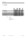
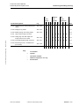
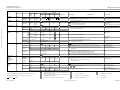
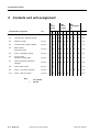
Contents/assignment
EC
Tachograph
-02
Contents
-24
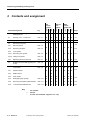
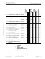
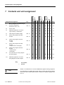
1
Page
1
General notes
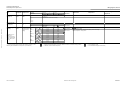
1.1
History - 1318
o
o
o
o
o
o
o
o
o
o
1-3
1.2
Preparing repairs
o
o
o
o
o
o
o
o
o
o
1-3
1.3
Repair hints
o
o
o
o
o
o
o
o
o
o
1-4
1.4
Workbench setup
Abb. 1-1
o
o
o
o
o
o
o
o
o
o
1-5
1.5
Auxiliary tools – detailed view
Abb. 1-2
o
o
o
o
o
o
o
o
o
o
1-6
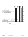
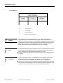
Key
1–2 Section 1
1-3
-
not available
o
optional
•
illustration available
*
additional equipment "01" only
**
discontinued
© Siemens VDO Trading GmbH
TU00-1318-0200302
Technical Product Manual
Fault analysis and repairs 1318
1
1.1
1 General notes
General notes
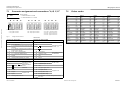
History - 1318
Year
Section 1: General notes • Edition 12/2005
1984
Remarks
KTCO 1318 introduction
•
1st pilot lot
from 10.000
•
2nd pilot lot
to 10.000
•
Series (Asic boards)
from 13.000
1985
From September with optical data output
from 20.000
1991
October: KTCO 1318 (EMC) introduced
from
582.000
1994
From December: µP units introduced
from
1.500.000
1995
•
Delivery to Mercedes Benz
•
New mounts, various front panels
•
Start: 05.94 (units with self-test function)
•
Final: 01.01.96 (law comes into force)
µP units, ADR version
•
1.2
Device
number
New barrier unit (current limiter) "STB 3"
Preparing repairs
Prior to any repair:
Voraussetzung
TU00-1318-0200302
•
Check recordings on tachograph chart.
•
Visually check all mechanical parts.
•
Visually check all electrical cables and components.
•
Check soldering points and conductors.
•
Check gear engagement.
•
Check that gears are running smoothly.
© Siemens VDO Trading GmbH
Section 1 1–3
1 General notes
1.3
Repair hints
Bemerkung
Lubrication
Electrical connections
•
Item numbers shown in the illustrations do not represent order numbers
•
For order numbers please refer to the Electronic Product Catalogue (EPC)
•
Any repair work on units up to manufacturing number 9.999 will be carried
out at head office in Villingen. Complete units must be sent in for repair.
When carrying out any repair work, lubricate the relevant parts in accordance
with Section 8.
For details on wiring diagrams please refer to Section 7.
Plug connections
Only remove mini-timer terminals and Ultrex connectors from the socket housing using the special tool designed for this purpose. Make sure that connectors are plugged in correctly and provide secure contact. Please refer to
Section 3 for a workflow description.
Soldered connections
Switch off the power to NEC / EC Tachographs before you carry out any soldering work. Carry out all soldering work with an electrically controlled, earthed
soldering unit and the necessary expertise.
With soldering you must ensure the following:
Bemerkung
Cabling
1–4 Section 1
•
The soldering tip must be no more than 0.5 mm.
•
Do not produce any cold soldering points.
•
Avoid any short circuits between the individual soldering points.
•
Remove any soldering spatters.
Run all cables without clamping and crushing them. The cables must not cause
any malfunctions in moving parts.
© Siemens VDO Trading GmbH
TU00-1318-0200302
Technical Product Manual
Fault analysis and repairs 1318
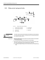
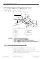
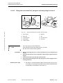
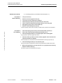
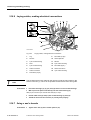
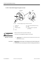
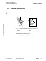
1.4
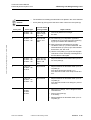
1 General notes
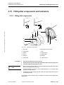
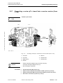
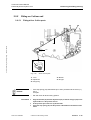
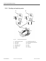
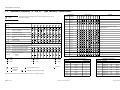
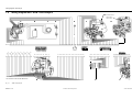
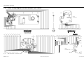
Workbench setup
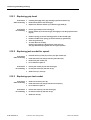
4
3
5
6
2
7
8
9
Section 1: General notes • Edition 12/2005
1
18
20
22
21
Fig. 1-1
14
16
17
19
15
12
11
10
13
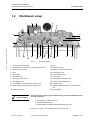
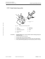
Workbench design
1
Tachograph chart turntable
12 Bolt
2
Tachograph chart analyser incl. measuring microscope
13 Indicator extractor
3
STC (incl. accessories)
14 Support for speed indicator shaft
4
BTC I
15 Tachograph mount
5
Rivet holder
16 Stylus adjustment tool
6
Adjustment disc
17 Riveting die
7
Conducting, earthed cover
18 Drilling support for tubular rivet
8
Test adapter 1318
19 Hood removal and fitting tool
9
Test adapter for 1318; STB barrier unit (no µP)
20 Analysing chart
10 Electronically controlled, earthed soldering unit
21 Clamping plate (complete) for 7 day adjustment
disc
11 Earthed wrist band
22 Test template
Voraussetzung
Please ensure when setting up the workbench that you heed the CMOS anti-static
protective measures:
Conducting, earthed cover (7)
Earthed wrist band (11)
Electronically controlled, earthed soldering unit (10)
Please refer to page 1-6 for a detailed view of the auxiliary tools.
TU00-1318-0200302
© Siemens VDO Trading GmbH
Section 1 1–5
1 General notes
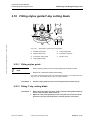
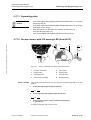
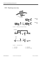
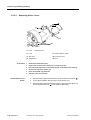
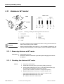
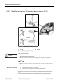
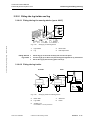
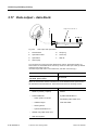
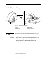
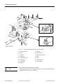
1.5
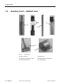
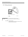
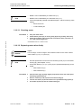
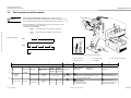
Auxiliary tools – detailed view
19
13
17
16
18
14
Fig. 1-2
1–6 Section 1
Auxiliary tools
13 Pointer extractor
17 Riveting die
14 Support for speed pointer shaft
18 Drilling support for tubular rivet
16 Stylus adjustment tool
19 Hood fitting tool
© Siemens VDO Trading GmbH
TU00-1318-0200302
Section 2: Removing and fitting housing cover • Edition 12/2005
Technical Product Manual
Fault analysis and repairs 1318
2 Removing and fitting housing cover
Section 2 Removing and fitting
housing cover
TU00-1318-0200302
© Siemens VDO Trading GmbH
Section 2 2–1
2 Removing and fitting housing cover
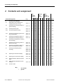
2
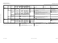
Contents and assignment
-26
-27
-02
-04
-06
-01
-03
-05
NEC
Tachographs CH
-25
NEC Tachographs
-24
EC
Tachographs
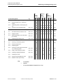
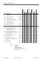
2
Removing and fitting
housing cover
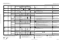
2.1
Housing cover – overall view
Abb. 2-1
o
o
o
o
o
o
o
o
o
o
2-7
2.2
Type plaque labelling
Abb. 2-2
o
o
o
o
o
o
o
o
o
o
2-8
2.3
Removing front parts
2.3.1
Removing bezel
Abb. 2-3
2.3.2
Replacing dial glass
Abb. 2-4
2.3.3
Lock cylinder
Contents/Assignment
Fig.
Page
2-9
o
2.3.3.1 Removing lock cylinder
Abb. 2-5
2.3.3.2 Fitting lock cylinder
Abb. 2-6
2.3.4
Replacing driver and lock bolt
Abb. 2-7
2.4
Modified cover and dial support (from
07.98)
Abb. 2-8
2.5
Removing indicators and dial
components
Abb. 2-9
2.5.1
o
o
o
o
o
o
o
o
o
2-10
o
o
o
o
o
o
o
o
o
o
2-11
o
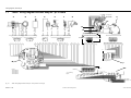
o
o
o
o
o
o
o
o
o
2-12
2-13
o
o
o
o
o
o
o
o
o
o
Speed indicator
o
o
o
o
o
o
o
o
o
o
2.5.2
RPM indicator
-
o
o
-
-
o
-
-
o
-
2.5.3
Clock hands
o
o
o
o
o
o
o
o
o
o
2.5.4
Disengaging stop springs
Abb. 2-10
o
o
o
o
o
o
o
o
o
o
2.5.5
Removing and replacing dial elements
Abb. 2-11
o
o
o
o
o
o
o
o
o
o
2-16
2.5.6
1318 with MOTOMETER dial
Abb. 2-12
o
o
o
o
o
o
o
o
o
o
2-17
2-14
2-15
Key
2–2 Section 2
-
not available
o
optional
*
for units with additional equipment "01" only
© Siemens VDO Trading GmbH
TU00-1318-0200302
Technical Product Manual
Fault analysis and repairs 1318
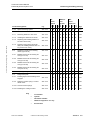
2 Removing and fitting housing cover
Contents/Assignment
Fig.
-26
-27
-02
-04
-06
-01
-03
-05
NEC
Tachographs CH
-25
NEC Tachographs
-24
Section 2: Removing and fitting housing cover • Edition 12/2005
EC
Tachographs
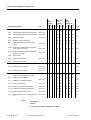
2.6
Removing cover plate/lamp plate
Abb. 2-13
-
o
o
-
-
o
-
-
o
-
2.6.1
Removing gears from n measuring
system
-
o
o
-
-
o
-
-
o
-
2.6.2
Unsoldering wires, contact spring and
coil
o
o
o
o
o
o
o
o
o
o
2.6.3
Removing cover plate/lamp plate
o
o
o
o
o
o
o
o
o
o
2.7
Flat cable
o
o
o
o
o
o
o
o
o
o
2.7.1
Flat cable versions for KTCO 1318
Abb. 2-15
o
o
o
o
o
o
o
o
o
o
2.7.2
Fitting flat cable
Abb. 2-16
o
o
o
o
o
o
o
o
o
o
2.7.3
Measuring adapter for new flat cable
(from 08.00)
Abb. 2-17
2.7.4
Replacing light emitting diode
Abb. 2-18
2.8
n measuring system
Abb. 2-19
2.8.1
Removing n measuring system
2.8.2
Removing stylus lever
2.8.3
Replacing gears
2.8.4
Removing contact springs with holder
on n measuring system
2.8.5
Abb. 2-14
Page
2-18
2-19
2-20
2-21
2-22
o
o
o
o
o
o
o
o
o
o
2-23
-
o
o
-
-
o
-
-
o
-
2-24
Abb. 2-20
-
o
o
-
-
o
-
-
o
-
2-25
Fitting contact spring and holder
Abb. 2-21
-
o
o
-
-
o
-
-
o
-
2-26
2.8.6
Checking integral potentiometer
Abb. 2-22
2.8.7
Checking DC motor
2.8.8
Removing and installing DC motor
Abb. 2-23
2.8.9
Modified n frame (from 02.00)
Abb. 2-24
2-27
-
o
o
-
-
o
-
-
o
2-28
Key
TU00-1318-0200302
-
not available
o
optional
*
for units with additional equipment "01" only
© Siemens VDO Trading GmbH
2-29
Section 2 2–3
2 Removing and fitting housing cover
-26
-27
-02
-04
-06
-01
-03
-05
NEC
Tachographs CH
-25
Contents/Assignment
NEC Tachographs
-24
EC
Tachographs
Page
o
o
o
o
o
o
o
o
o
o
2-30
Abb. 2-26
o
o
o
o
o
o
o
o
o
o
Abb. 2-26
o
o
o
o
o
o
o
o
o
o
o
o
o
o
o
o
o
o
o
o
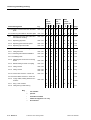
Fig.
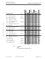
2.9
Quartz mechanismk
2.9.1
Checking fibre glass quartz mechanism
Abb. 2-25
2.9.2
Removing fibre glass quartz mechanism
2.9.3
Replacing gears
2.9.4
Modified quartz mechanism
2-31
2-32
2.9.4.1 Fibre glass quartz mechanism (from
11.96)
Abb. 2-27
o
o
o
o
o
o
o
o
o
o
2.9.4.2 Clockwork mechanism bridge with flat
cable guide (from 07.97)
Abb. 2-28
o
o
o
o
o
o
o
o
o
o
2.9.4.3 Quartz mechanism made of transparent
plastic (from 03.98)
Abb. 2-29
2-34
Abb. 2-30
2-35
2.9.5
2-33
Speed shaft
2.9.5.1 Replacing speed shaft
2.9.5.2 Checking speed shaft
2.10
Cover contact
2.10.1
Replacing cover contact
Abb. 2-31
Abb. 2-32
2.10.2
Checking cover contact
Abb. 2-33
2.11
Fitting quartz mechanism, n measuring
system, lamp plate and cover plate
2.11.1
Fitting quartz mechanism
-
-
o
o
-
-
-
-
-
-
-
-
o
o
-
-
-
-
-
-
2-36
2-37
o
o
o
o
o
o
o
o
o
o
o
o
o
o
o
o
o
o
o
o
-
o
o
-
-
o
-
-
o
-
Abb. 2-34
2-38
2-39
2.11.2
Fitting the n measuring system
2.11.3
Fitting n stylus lever
Abb. 2-35
-
o
o
-
-
o
-
-
o
-
2-40
2.11.4
Fitting cover plate and lamp plate
Abb. 2-36
o
o
o
o
o
o
o
o
o
o
2-41
2.11.5
Clockwork mechanism malfunction
Abb. 2-37
o
o
o
o
o
o
o
o
o
o
2-42
2.11.6
Making electrical connections
Abb. 2-38
-
o
o
-
-
o
-
-
o
-
2-43
2.11.7
n measuring system - Inserting spur gears
Abb. 2-39
-
o
o
-
-
o
-
-
o
-
2-44
Key
2–4 Section 2
-
not available
o
optional
*
for units with additional equipment "01" only
© Siemens VDO Trading GmbH
TU00-1318-0200302
Technical Product Manual
Fault analysis and repairs 1318
2 Removing and fitting housing cover
-26
-27
-02
-04
-06
-01
-03
-05
NEC
Tachographs CH
-25
NEC Tachographs
-24
EC
Tachographs
o
o
o
o
o
o
o
o
o
o
Abb. 2-40
o
o
o
o
o
o
o
o
o
o
Making auxiliary bezel
Abb. 2-41
o
o
o
o
o
o
o
o
o
o
2.12.3
Fitting n and v indicators
Abb. 2-42
o
o
o
o
o
o
o
o
o
o
2.12.4
Checking indicator running
o
o
o
o
o
o
o
o
o
o
2.12.5
Checking engagement depth
Abb. 2-43
o
o
o
o
o
o
o
o
o
o
2-48
2.12.6
Fitting clock hands
Abb. 2-44
o
o
o
o
o
o
o
o
o
o
2-49
2.12.7
Modified hands for IVECO version.
2.12.8
Fitting bezel
Abb. 2-45
o
o
o
o
o
o
o
o
o
o
2.13
Removing cover plate and knobs
o
o
o
o
o
o
o
o
o
o
2-51
2.13.1
Removing cover plate
Abb. 2-46
2.13.2
Pulling out knobs
Abb. 2-47
o
o
o
o
o
o
o
o
o
o
2-52
2.14
Distance recorder
o
o
o
o
o
o
o
o
o
o
2.14.1
Setting counter
2.14.2
Removing distance counter
Contents/Assignment
Fig.
2.12
Fitting dial components and indicators
2.12.1
Fitting dial components
2.12.2
Page
2-45
2-46
Section 2: Removing and fitting housing cover • Edition 12/2005
2-47
2-50
2-53
Abb. 2-48
o
o
o
o
o
o
o
o
o
o
2-54
Abb. 2-49
2.14.3
Fitting distance counter
o
o
o
o
o
o
o
o
o
o
2.15
Fitting cover plate and knobs
o
o
o
o
o
o
o
o
o
o
2.15.1
Fitting knobs
o
o
o
o
*
*
*
o
o
o
2-55
2-56
2.15.1.1 Modified knobs
Abb. 2-50
2.15.1.2 Inserting knobs
Abb. 2-51
2-57
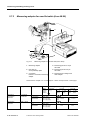
2.15.2
Cover plate versions
Abb. 2-52
2-58
2.15.3
Fitting cover plate
Abb. 2-53
Abb. 2-54
key
TU00-1318-0200302
o
o
o
o
o
o
-
not available
o
optional
*
for units with additional equipment "01" only
© Siemens VDO Trading GmbH
o
o
o
o
2-60
Section 2 2–5
2 Removing and fitting housing cover
Contents/Assignment
Fig.
-26
-27
-02
-04
-06
-01
-03
-05
NEC
Tachographs CH
-25
NEC Tachographs
-24
EC
Tachographs
2.16
Fitting stylus guide/7-day cutting blade
Abb. 2-55
o
o
-
-
o
o
-
o
o
-
2.16.1
Fitting stylus guide
-
-
-
-
-
-
o
-
-
o
2.16.2
Fitting 7-day cutting blade
2.16.3
Modified cutting blade (from 05.99)
2.17
Replacing separating plate and cover
2.17.1
Replacing plate on defective covers
2.17.2
Replacing defective separating plate
2.17.3
Separating plate
2.17.4
Secure contact with 318 warning LED
(from 05.97)
2.18
Replacing cover and cover strap
2.18.1
Replacing coverl
2.18.2
Modified cover dimensions (from
01.96)
2.18.3
Replacing cover strap
Key
2–6 Section 2
Abb. 2-56
Page
2-61
2-62
-
-
o
o
-
-
-
-
-
-
-
-
o
o
-
-
-
-
-
-
2-64
Abb. 2-57
2-65
Abb. 2-58
o
o
o
o
o
o
o
o
o
o
Abb. 2-59
Abb. 2-60
o
o
o
o
o
o
o
o
o
o
Abb. 2-61
o
o
o
o
o
o
o
o
o
o
2-66
Abb. 2-62
Abb. 2-63
-
not available
o
optional
*
for units with additional equipment "01" only
© Siemens VDO Trading GmbH
2-67
2-68
TU00-1318-0200302
Technical Product Manual
Fault analysis and repairs 1318
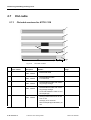
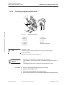
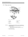
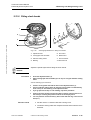
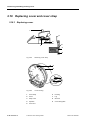
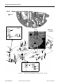
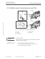
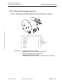
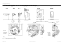
2.1
2 Removing and fitting housing cover
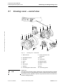
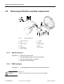
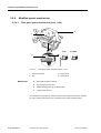
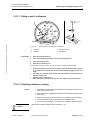
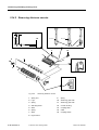
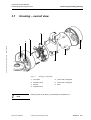
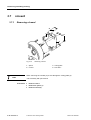
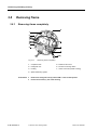
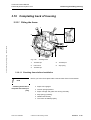
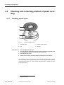
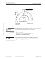
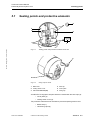
Housing cover – overall view
8
10
11
12
Section 2: Removing and fitting housing cover • Edition 12/2005
9
5
2
3
6
7
4
13
15
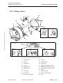
Fig. 2-1
Note
TU00-1318-0200302
16
17
1
14
Housing cover – overall view
1
Bezel with lock
9
Quartz mechanism with
speed shaft
2
Speed/RPM indicator
10 Cover
3
Dial glass
11 Type plaque
4
Panel
12 Separating plate
5
Dial
13 Distance counter
6
Dial support
14 Cover
7
Reflector
15 Knob
8
Cover/lamp plate with flat cable
16 n measuring system
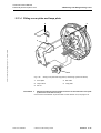
Repair hint:
The steps to be carried out when repairing the 1318.40 tachograph are similar
to the ones for the 1318 tachograph. Its main components are constructed in
the same way as the EC/NEC; special components are listed in the Electronic
Product Catalogue (EPC).
© Siemens VDO Trading GmbH
Section 2 2–7
2 Removing and fitting housing cover
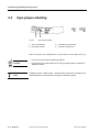
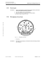
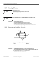
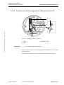
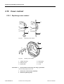
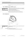
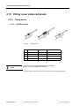
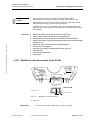
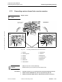
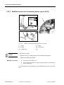
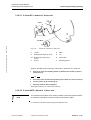
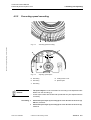
2.2
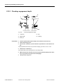
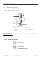
Type plaque labelling
3
1
Fig. 2-2
4
2
Type plaque labelling
1
Year of manufacture
3
1318 without µP electronics
2
Device/type number
4
1318 with µP electronics
When servicing the unit, complete fields (1), (2) and make a note of labels (3) and (4).
•
From 04.94: black, laser-marked type plaque.
Remark
•
From 03.95, the numbers 80 to 86 on the type plaque (item 2) identify an
ADR/STB version.
Note
Installing µP units – ADR version – without barrier unit into 24 V vehicles is permitted if these are not used for the carriage of hazardous goods.
2–8 Section 2
© Siemens VDO Trading GmbH
TU00-1318-0200302
Technical Product Manual
Fault analysis and repairs 1318
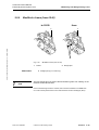
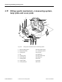
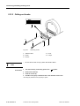
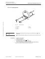
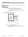
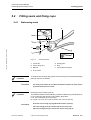
2.3
2 Removing and fitting housing cover
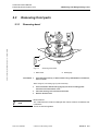
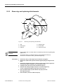
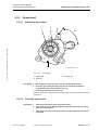
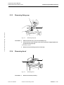
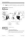
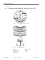
Removing front parts
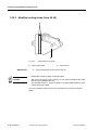
2.3.1
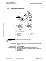
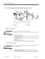
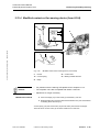
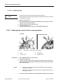
Removing bezel
Section 2: Removing and fitting housing cover • Edition 12/2005
1
1
2
2
Fig. 2-3
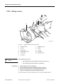
1
Procedure
H
Removing bezel seals
Bezel seals
2
Sealing lugs
Press the bezel seals (1) in about 3-5 mm using a watchmaker's screwdriver,
max. Ø 1.9 mm.
When doing this, the sealing lugs (2) will break away.
H
H
H
Note
TU00-1318-0200302
Press used seals without sealing lugs (2) into the four sealing points
until these are flush with the cover.
Close the housing cover and remove the bezel.
Remove all bezel seals.
Bezel versions:
The 1318 Electronic Product Catalogue lists various versions for different manufacturers.
These are interchangeable.
© Siemens VDO Trading GmbH
Section 2 2–9
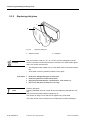
2 Removing and fitting housing cover
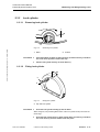
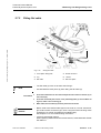
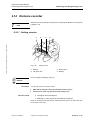
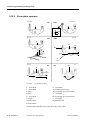
2.3.2
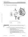
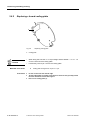
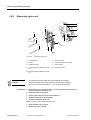
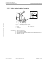
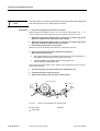
Replacing dial glass
1
2
Fig. 2-4
1
Remark
Procedure
Note
Replacing dial glass
Adhesive surface
2
Dial glass
With unit versions 1318-03, -04, -25, -26 only concave plexiglass must be
used. For all other versions and versions 1318.2570 and .2670 silicate glass
that is not curved must be used.
•
The dial glass must be fitted in such a way that it rests on the bezel completely.
•
There must not be any adhesive residue on the glass.
H
H
H
H
Remove the damaged dial glass from the bezel.
Remove any adhesive residue from the bezel.
Apply the prescribed adhesive, "Delomet 2301", to the surface (1).
Insert a new dial glass (2) and press it on firmly.
Cleaning dial glass:
Cleaning materials must not contain alcohol and affect the antireflection coating.
Use the intensive plastic cleaner supplied by us.
The cleaner is ready for use and can be applied using a soft cloth.
The order number can be found in the 1318 Electronic Product Catalogue.
2–10 Section 2
© Siemens VDO Trading GmbH
TU00-1318-0200302
Technical Product Manual
Fault analysis and repairs 1318
2.3.3
2 Removing and fitting housing cover
Lock cylinder
2.3.3.1
Removing lock cylinder
1
b
a
2
Section 2: Removing and fitting housing cover • Edition 12/2005
Fig. 2-5
1
Procedure
H
H
2.3.3.2
Removing lock cylinder
Bezel
2
Tumbler
Press the tumbler (2) down so that it points to (a) and turn the key in the direction of the arrow (b) until it reaches the stop.
Pull the lock cylinder and key out of the bezel (1).
Fitting lock cylinder
45
c
3
Fig. 2-6
Procedure
Fitting lock cylinder
3
Key with lock cylinder
H
Insert the lock cylinder and key (3) into the bezel.
When doing this, the protruding MS tumbler of the lock cylinder must point to the left
bezel edge.
H
TU00-1318-0200302
Insert the lock cylinder until it is flush with the bezel, turn the key in the direction of the arrow (c) until the tumbler locks into place.
© Siemens VDO Trading GmbH
Section 2 2–11
2 Removing and fitting housing cover
2.3.4
Replacing driver and lock bolt
from
to 11.93
4
5
4
5
3
1
2
Fig. 2-7
Remark
Procedure
2–12 Section 2
1
Replacing driver and lock bolt
1
Drive
4
Lock bolt
2
Compensating washers
5
Screw
3
Seal
When closed, the cover must be flush with the housing and must not have any
play.
H
H
H
H
H
Undo the screw (5).
Remove the driver (1), compensating washers (2) (until 11.93) and lock bolt (4).
Replace the self-adhesive seal (3) (until 11.93) if necessary.
Tighten the compensating washers (2) lightly and put them on the driver (1).
Put the lock bolt (4) on the driver (1) and fasten the screw.
© Siemens VDO Trading GmbH
TU00-1318-0200302
Technical Product Manual
Fault analysis and repairs 1318
2.4
2 Removing and fitting housing cover
Modified cover and dial support (from 07.98)
1
3
Section 2: Removing and fitting housing cover • Edition 12/2005
2
4
Fig. 2-8
Modification
Cover with modified stop bolts and correct dial support
1
Reinforced parts
3
Dial support
2
Stop bolts
4
Hold-down device
Specially designed stop bolts (2) for fitting the cover plate/lamp plate more
easily.
Hold-down devices (4) fitted on the dial support (3) to ensure that the cover
plate/lamp plate stays in place better.
Fitting a new cover to the reinforced parts (1) during repairs:
Fitting a new cover 1318.0101.010.007 with the correct dial support
1318.0101.016.001 or 1318.0101.065.002
Remark
Start of production in July 1998, from device number 2.745.771.
Dial support (3) with hold-down devices (4) is compatible with all cover versions.
Order number
Order number
Previous order number
Description
Remarks
1318.0101.010.007
1318.0101.010.005
Cover
EC and NEC without 1/min,
1318.0101.009.003 1/min,
based on 1318.0101.010.007.
1318.0101.016.001
1318.0101.016.000
Dial support
1318.0101.065.002
1318.0101.065.001
Dial support
TU00-1318-0200302
© Siemens VDO Trading GmbH
for Iveco
Section 2 2–13
2 Removing and fitting housing cover
2.5
Removing indicators and dial components
19
2
4
6,
2
5
4
1
3
6
7
8
9
11
2
Fig. 2-9
2.5.1
Removing indicators
1
Indicator extractor
7
Washer
2
Cap
8
Ring *
3
Speed indicator
9
Minute hand *
4
Ring
10 Ring *
5
RPM indicator
11 Hour hand *
6
Second washer
Speed indicator
Procedure
2.5.2
10
H
H
H
H
Remove the cap (2) by hand.
Insert the indicator remover (1) exactly in the middle.
Turn the indicator extractor (1) clockwise.
Remove the speed indicator (3).
RPM indicator
Procedure
Remark
2–14 Section 2
H
Turn the RPM indicator (5) and the ring (4) and remove by hand.
Items 8-11*
From 04.01 indicators and rings can only be ordered together.
© Siemens VDO Trading GmbH
TU00-1318-0200302
Technical Product Manual
Fault analysis and repairs 1318
2.5.3
2 Removing and fitting housing cover
Clock hands
Procedure
H
H
H
Turn the second washer (6), minute hand (9) and hour hand (11) and remove
them by hand together with items (7), (8) and (10).
The ring (7) engages into the seconds plate (6).
Rings (4), (8) and (10) are engaged into the relevant indicator.
The rings prevent light escaping from the side.
Disengaging stop springs
Section 2: Removing and fitting housing cover • Edition 12/2005
2.5.4
1
1
Fig. 2-10
1
Procedure
TU00-1318-0200302
H
Disengaging stop springs
Stop springs
Disengage the stop springs (1) in the direction of the arrow using a watchmaker's screwdriver.
© Siemens VDO Trading GmbH
Section 2 2–15
2 Removing and fitting housing cover
2.5.5
Removing and replacing dial elements
2
3
1
4
6
5
Fig. 2-11
1
Dial
4
Adhesive tape
2
Dial support
5
Diode holder
3
Reflector
6
Indicator stop pin
•
Put a leather cloth or a clean cloth on the dial to prevent it from getting dirty
(stains etc.).
•
The diode holder (5), indicator stop pin (6) and adhesive tape (4)
are used to connect the dial (1) and dial support (2).
Remark
Procedure
H
H
H
H
H
H
H
2–16 Section 2
Removing and replacing dial elements
Remove the dial (1), dial support (2) and reflector (3) together.
Remove the diode holder (5) from the dial support (2) by pressing from the
back.
Remove the indicator stop pin (6), max. Ø 1.4 mm, from the dial support (2)
from the back. When doing this, do not damage the dial.
Carefully remove the dial (1) from the adhesive tape (4).
Hold the new dial by the edges and put in on the dial support (2)
in such a way that the adhesive tape does not stick to it.
Press the diode holder (5) and indicator stop pin (6) into the
dial support (2) again.
Press the dial (1) onto the adhesive tape (4).
© Siemens VDO Trading GmbH
TU00-1318-0200302
Technical Product Manual
Fault analysis and repairs 1318
2 Removing and fitting housing cover
From 07.97 modified indicator stop pin (6):
Longer indicator stop pin (6) introduced for DC version (RPM units).
Note
Modification
Indicator stop pin (6) with 10 mm standard length changed to 13.2 mm special length
For order numbers please refer to the 1318 Electronic Product Catalogue (EPC).
2.5.6
1318 with MOTOMETER dial
Section 2: Removing and fitting housing cover • Edition 12/2005
1
2
Fig. 2-12
1
MOTOMETER dial
Dial
2
Company logo
When carrying out any service work or technical checks, 1318 units – MOTOMETER
version – must be handled in the same way as units from Siemens VDO Automotive.
Units supplied with Motometer dial:
Note
•
1318.02
•
1318.04
•
1318.24
•
1318.27
For order numbers please refer to the 1318 Electronic Product Catalogue (EPC).
TU00-1318-0200302
© Siemens VDO Trading GmbH
Section 2 2–17
2 Removing and fitting housing cover
2.6
Removing cover plate/lamp plate
1
2
3
4
5
6
11
7
8
10
9
Fig. 2-13
2.6.1
1
Cover plate
7
Lamp plate
2
Cover contacts
8
Quartz mechanism
3
n system contact spring
9
Warning LED
4
Wires
10 Warning LED
5
Spur gears
11 Coil connections
6
n measuring system
Removing gears from n measuring system
Procedure
2.6.2
Housing cover without dial elements (RPM units)
H
Remove the spur gears (5).
Unsoldering wires, contact spring and coil
Procedure
H
H
H
H
2–18 Section 2
Unsolder all six wires (4) and the contact spring (3).
Remove any solder using desolder wire or by suction using an automatic vacuum pump.
Unsolder cover contacts (2) and coil connections (11).
Remove any solder using desolder wire or by suction using an automatic vacuum pump.
© Siemens VDO Trading GmbH
TU00-1318-0200302
Technical Product Manual
Fault analysis and repairs 1318
2.6.3
2 Removing and fitting housing cover
Removing cover plate/lamp plate
2
2
1
Section 2: Removing and fitting housing cover • Edition 12/2005
a
4
Fig. 2-14
Note
Procedure
3
Removing cover plate/lamp plate
1
Flat cable
3
Lamp plate
2
Stop bolts
4
Cover plate
•
The five stop bolts (2) hold the cover plates (4) and lamp plate (3) in place.
•
When removing the two plates, do not press the stop bolts together.
H
H
H
H
H
H
H
TU00-1318-0200302
b
Remove the bulbs from the holder by turning them anti-clockwise.
Insert the screwdriver into (a) and remove the cover plate (4) by lifting it over
the bevel of the lamp holder.
Repeat by inserting the screwdriver into (b).
Pull the cover plate (4) and flat cable (1) out of the stop bolts (2).
Carefully remove the lamp plate (3) from the stop bolts (2) by hand.
Lift the cover plate/lamp plate in the area of the distance counter and
remove without damaging the contact springs.
Turn the cover plate (4) and carefully pull the flat cable (1) out of the socket
connector.
© Siemens VDO Trading GmbH
Section 2 2–19
2 Removing and fitting housing cover
2.7
Flat cable
2.7.1
Flat cable versions for KTCO 1318
1
2
3
4
A
5
B
D
C
Fig. 2-15
Flat cable versions
E
No
.
Order number
Description
Remarks
Usage
1
HS53-6800-695
Flat
cable, 16x250
•
Flexible flat cable
from 04.84 to 03.98
2
HS53-6800-039
Flat
cable, 16x250
•
Ultra-flexible flat cable
0.12 mm thick
from 04.98 to 09.98
3
HS53-6800-040
Flat
cable, 16x250
•
Ultra-flexible flat cable with reinforcing foil (A) at hinge
from 09.98 to 03.00
4
HS53-6800-040
Flat
cable, 16x250
•
Ultra-flexible flat cable with reinforcing foil (A) at hinge
from 09.98 to 03.00
•
Cover side marked in white on reinforced part (B)
•
Area (C) reinforced from 0.12 mm
to 0.17 mm
•
Area (D), 0.12 mm thick
•
Reinforced part (E) extended by 19
mm
5
HS53-6800-042
2–20 Section 2
Flat
cable, 16x250
© Siemens VDO Trading GmbH
from 03.00
TU00-1318-0200302
Technical Product Manual
Fault analysis and repairs 1318
2.7.2
2 Removing and fitting housing cover
Fitting flat cable
5
4
Section 2: Removing and fitting housing cover • Edition 12/2005
6
2
3
1
Fig. 2-16
Note
Procedure
1
Cover plate / lamp plate
4
Socket connector
2
Lug
5
v board
3
Flat cable
6
Flat-nose pliers
•
The flat cable (3) must not be bent when fitting it.
•
Use standard flat-nose pliers (6) when fitting the flat cable (3).
H
H
H
Insert the end with the 19 mm reinforced part into the socket connector (4) on
the v board (5).
Insert the reinforced part into the cover plate/lamp plate (1) 10 mm. When doing this, make a note of the lug (2).
When fitted, the flat cable (3) must be positioned as shown.
•
Before 1994: Insert the flat cable (3)into units 1318-04, -25 and –26 with single-contact socket connectors (4) in such a way that contact is being made.
Contacts are no longer accessible for troubleshooting.
See Chapter 2.7.3 for troubleshooting instructions.
•
Improving tachograph repairs:
When replacing a defective clockwork mechanism, fit the latest ultra-flexible
flat cable too.
Remark
TU00-1318-0200302
Fitting flat cable
© Siemens VDO Trading GmbH
Section 2 2–21
2 Removing and fitting housing cover
2.7.3
Measuring adapter for new flat cable (from 08.00)
3
1
2
6
4
5
Fig. 2-17
Measuring adapter for new flat cable (from 08.00)
1
Measuring adapter
4
Measuring points for 16-pin
flat cable
2
Flat cable on
cover plate/lamp plate
5
Measuring points for 8-pin
flat cable
3
Connection
between v board and measuring
adapter
6
Measuring point assignment/
fault analysis
Please refer to Chapter "7.6.1 Fault analysis - "Basic" microprocessor v board (µP)"
Error
Component 1
Component 2
Component 1voltage check
Measuring
point
colour
Clockwork
mechanism
defective
K clockwork
mechanism
Illumination
defective
M/M1 v board
2–22 Section 2
Conductor
no. ()
K clockwork
mechanism
Flat cable
23 + (4) ((8))
24 + (5) ((10))
H1
Illumination
Flat cable
25 + (6) ((12))
22 + (3) ((6))
© Siemens VDO Trading GmbH
12 V unit
v=0
km/h
v = 60
km/h
0 V ...> 3.3 V
imp
12 V
24 V unit
v=0
km/h
v = 60
km/h
0 V ...> 3.3 V
imp
24 V
TU00-1318-0200302
Technical Product Manual
Fault analysis and repairs 1318
2 Removing and fitting housing cover
The adapter can be used for both 8-pin and 16-pin flat cables. For order numbers please
refer to the 1318 Electronic Product Catalogue (EPC).
2.7.4
Replacing light emitting diode
Section 2: Removing and fitting housing cover • Edition 12/2005
3
1
1
2
2
Fig. 2-18
TU00-1318-0200302
Replacing light emitting diode
1
Self-adhesive seal
2
LED
•
Depending on the customer-specific version, the LED (2) is either red or yellow.
•
When soldering LED's, make a note of the correct polarity.
•
Area (3) is the cathode connection.
Remark
Procedure
3
H
H
H
3
Cathode connection (area)
Remove the self-adhesive seal (1).
Unsolder the LED (2).
Insert the seal (1).
© Siemens VDO Trading GmbH
Section 2 2–23
2 Removing and fitting housing cover
2.8
n measuring system
1
2
3
4
a
6
5
Fig. 2-19
2.8.1
1
Stylus lever
4
Tension spring
2
Retaining washer
5
Spur gears
3
Filister head screw
6
Retaining washer
Removing n measuring system
Procedure
H
H
H
2.8.2
Unhook the tension spring (4) and move the stylus lever (1) in the direction of
the arrow (a).
Undo the filister head screw (3).
Remove the n measuring system.
Removing stylus lever
Procedure
2.8.3
Removing n measuring system
H
H
Remove the retaining washer (2).
Remove the stylus lever (1).
Replacing gears
Procedure
2–24 Section 2
H
H
H
Remove the retaining washer (6).
Remove the spur gears (5).
Put the spur gears (5) on again (no specific order).
© Siemens VDO Trading GmbH
TU00-1318-0200302
Technical Product Manual
Fault analysis and repairs 1318
2.8.4
2 Removing and fitting housing cover
Removing contact springs with holder on n measuring system
1
6
5
2
Section 2: Removing and fitting housing cover • Edition 12/2005
4
4
3
Fig. 2-20
Remark
Procedure
TU00-1318-0200302
Removing contact springs on n measuring system
1
Contact carrier
4
Catch lug
2
Contact path
5
Contact spring with holder
3
Contract spring with holder
6
n frame
If this component is defective, replace the n frame (6) and integral potentiometer unit.
H
Remove the contact springs and holders (3) and (5) by disengaging the catch
lugs (4).
© Siemens VDO Trading GmbH
Section 2 2–25
2 Removing and fitting housing cover
2.8.5
Fitting contact spring and holder
6
1.2
b
6.8+0.5
4
3
5
2
1
6
7
Fig. 2-21
Remark
Procedure
Fitting contact spring and holder
1
Contact spring with holder
5
Contact path
2
Contact spring with holder
6
Driver plate
3
Contact rivet
7
Spur gear
4
Driver contact
•
The driver contact (4) and contact path (5) are welded to the driver plate (6).
•
The driver plate (6) is located on the same axle as the integral potentiometer's resistor and spur gear (7).
H
With the contact spring (1) the contact rivet (3) must extend over the fictious
line (b) (pre-tensioned).
The contact sits firmly on the spur gear's (7) contact path.
H
When fitted, adjust the contact rivet (3) on the contact spring and the holder
(2) in such a way that they are level with the driver contact (4).
Contacts (3) and (4) sit firmly on the contact carrier's (7) contact path. (Fig.
2-20)
2–26 Section 2
© Siemens VDO Trading GmbH
TU00-1318-0200302
Technical Product Manual
Fault analysis and repairs 1318
2.8.6
2 Removing and fitting housing cover
Checking integral potentiometer
3
2
p
5
wt-
1
wt
r
6
7 bk
4
8 9 10
Section 2: Removing and fitting housing cover • Edition 12/2005
11
Fig. 2-22
Checking potentiometer
1
Wire wt
7
Wire bk
2
Wire wtr
8
Motor pinion
3
Wire pink
9
Collar
4
Spur gear
10 Motor
5
n frame
11 Filister head screws
6
Wire red
Defective n frame:
Resistance value changes abruptly when turning the spur gear (4).
Note
Action to be taken:
Replace the n frame (5) and integral unit.
•
Depending on the direction of rotation of the spur gear (4)
, the resistance value must increase or decrease steadily (about 170 Ω...5
KΩ).
•
The measured value on the wires must not exceed 5 KΩ ± 10%
.
Remark
Procedure
TU00-1318-0200302
H
H
H
H
Connect a measuring device between wires (1) and (3).
Determine the resistance value.
Connect the measuring device to wires (2) and (3).
Turn the spur gear (4) slowly and steadily to determine the resistance value.
© Siemens VDO Trading GmbH
Section 2 2–27
2 Removing and fitting housing cover
2.8.7
Checking DC motor
Defective DC motor:
Resistance value changes abruptly when turning
on the motor pinion (8).
Note
Action to be taken:
Replace the DC motor.
The measured value on the wires must not exceed 50 Ω ± 12%.
Note
Procedure
2.8.8
H
H
H
H
Visually check the DC motor.
Check that the motor pinion is running (8) freely.
Connect a measuring device between wires (6) and (7).
Turn the motor pinion (8) steadily to determine the resistance value.
Removing and installing DC motor
6
7
a
10
11
Fig. 2-23
Checking, removing and installing DC motor
6
Wire
10 Motor
7
Wire
11 Filister head screws
9 Collar
Procedure
H
H
Undo the filister head screws (11) and pull the motor (10) out.
Insert a replacement motor and run wires (6) and (7) as shown in Abb. 2-22.
The collar (9) enables the motor to be centred precisely.
H
2–28 Section 2
Screw the filister head screws (11) on.
© Siemens VDO Trading GmbH
TU00-1318-0200302
Technical Product Manual
Fault analysis and repairs 1318
2.8.9
2 Removing and fitting housing cover
Modified n frame (from 02.00)
from
to 02.00
Section 2: Removing and fitting housing cover • Edition 12/2005
1
1
2
Fig. 2-24
1
Modification
Note
Modified n frame (from 02.00)
n frame
2
Straight pins
Straight pins (2) on n frame (1).
The two straight pins (2) prevent the transmission gears from rubbing on the
reflector located above them.
From manufacturing number 3.018.818, this has been standard on all RPM units.
For order number please refer to the 1318 Electronic Product Catalogue (EPC).
TU00-1318-0200302
© Siemens VDO Trading GmbH
Section 2 2–29
2 Removing and fitting housing cover
2.9
Quartz mechanism
3
1
2
C
1
5
3
4
B
A
6
1
Observe the anti-static
protective measures
Fig. 2-25
2.9.1
Checking quartz mechanism
1
Filister head screws (3x)
4
Quartz mechanism
2
Bridge
5
Flat cable guide
3
Bridge
6
1311 electronic quartz board
Checking fibre glass quartz mechanism
Remark
Visual checks
With 1318 units the quartz electronic unit is located on the v board.
To check the clockwork mechanism, the mechanism’s electronic quartz board
(6) must be controlled by the 1311 unit.
H
H
Checking coil
resistance
Checking mechanism
function
H
H
H
H
H
Check that all gears are running smoothly and have play.
When doing this, make a note of foreign bodies and damaged gears.
Bridges (2) and (3) must be seated firmly so that all the indicator adjustment
gears engage properly.
Connect a measuring devices to points (B) and (C).
The measured value must not exceed 1.5 to 2 KΩ.
Replace the mechanism if the resistance value is outside tolerances.
Push the clock hands and second hand down onto point (A).
Replace the mechanism completely if time differences are outside permissible
tolerances.
For tolerances please refer to the TPH, TU00.1308.01 000 01, Section 3, Chapter 8.
From 09.93 the bridge (3) has a flat cable guide (5).
2–30 Section 2
© Siemens VDO Trading GmbH
TU00-1318-0200302
Technical Product Manual
Fault analysis and repairs 1318
2.9.2
2 Removing and fitting housing cover
Removing fibre glass quartz mechanism
to 08.93
from
Section 2: Removing and fitting housing cover • Edition 12/2005
0.7
1.05
1
5
4
3
Fig. 2-26
Procedure
2.9.3
2
Replacing gears
1
Board
4
Spring
2
Spring washer
5
Change gear
3
Change gear
H
H
Undo the filister head screws (1) Abb. 2-25.
Remove the mechanism from the housing cover.
Replacing gears
The spring washer (2) underneath the change gear (3) is not necessary if the
modified change gear (5) with moulded springs (4) is used.
Note
Procedure
H
All the gears at the top of the board (1) must be replaced if defective.
No additional repair release will be given.
Remark
TU00-1318-0200302
© Siemens VDO Trading GmbH
Section 2 2–31
2 Removing and fitting housing cover
2.9.4
Modified quartz mechanism
2.9.4.1
Fibre glass quartz mechanism (from 11.96)
2
1
from
to 10.96
3
4
Fig. 2-27
Modification
Fibre glass quartz mechanism (from 11.96)
1
Quartz mechanism
3
Fixing points
2
Side
4
Rotary drive
Gears fully enclosed - side (2).
Improved gear (not shown)
Additional fixing points (3) on stator plates.
Longer rotary drive (4).
From manufacturing number 2.155.675 and since week 45/96, this has been standard.
For order number please refer to the 1318 Electronic Product Catalogue (EPC).
2–32 Section 2
© Siemens VDO Trading GmbH
TU00-1318-0200302
Technical Product Manual
Fault analysis and repairs 1318
2.9.4.2
2 Removing and fitting housing cover
Clockwork mechanism bridge with flat cable guide (from 07.97)
3
1
1
Section 2: Removing and fitting housing cover • Edition 12/2005
2
2
Fig. 2-28
Modification
1
Bridge
2
Guide
Bridge with guide on mechanism
3
Flat-ribbon cable
Flat cable (3) guide (2) on bridge (1).
Bridge (1) is included in the 1318.0106.060.000 parts kit. Standard since manufacturing
number 2.356.426.
For order numbers please refer to the 1318 Electronic Product Catalogue (EPC).
TU00-1318-0200302
© Siemens VDO Trading GmbH
Section 2 2–33
2 Removing and fitting housing cover
2.9.4.3
Quartz mechanism made of transparent plastic (from 03.98)
1
2
3
Fig. 2-29
Note
Clockwork mechanism made of transparent plastic
1
Quartz mechanism
2
Rotor cover
3
Coil pins
When unsoldering and soldering the clockwork coil, there is a high risk that the
coil pins (3) will be displaced and the coil wire will break.
With soldering you must ensure the following:
Modification
•
Do not apply too much heat for too long a time.
•
Do not exert any force on the cover plate/lamp plate.
•
Remove any solder using desolder wire or by suction using an automatic
vacuum pump.
Material: transparent plastic instead of glass fibre.
Rotor cover (2) fitted to bridge.
For order numbers please refer to the 1318 Electronic Product Catalogue (EPC).
2–34 Section 2
© Siemens VDO Trading GmbH
TU00-1318-0200302
Technical Product Manual
Fault analysis and repairs 1318
2.9.5
2 Removing and fitting housing cover
Speed shaft
2.9.5.1
Replacing speed shaft
2
1
3*
Section 2: Removing and fitting housing cover • Edition 12/2005
A
3*
Fig. 2-30
Procedure
Speed shaft
1
Speed shaft
2
Driver pin
H
H
H
* see paragraph 2.10.1
3
Centring pins
Pull the defective speed shaft (1) from the clockwork mechanism.
Insert the speed shaft (48.8 mm long) into the clockwork mechanism
so that the driver pin (2) is located in area (A).
Push the speed shaft in up to the stop.
Because of the pressure spring and the torsion spring in the mechanism, the shaft will
spring back.
2.9.5.2
Checking speed shaft
Procedure
H
H
H
TU00-1318-0200302
Push the speed shaft (1) down using flat tweezers.
Turn the driver pin (2) about 90 degrees in both directions and let it spring
back to its initial position.
If the driver pin (2) does not spring back to area (A), replace the mechanism
completely.
© Siemens VDO Trading GmbH
Section 2 2–35
2 Removing and fitting housing cover
2.10 Cover contact
2.10.1 Replacing cover contact
3
1
2
4
Fig. 2-31
Removing cover contact
1
6
5
Fig. 2-32
Procedure
Riveting cover contact
1
Tubular rivet head
4
Rivet holder
2
Drilling support
5
Contact kit
3
Riveting dies
6
Cover
H
Drill the tubular rivet head (1) out using a grooved bit.
Use the drilling support (2) for this.
H
H
2–36 Section 2
Remove the contact kit (5) completely.
Remove any drilling chips.
© Siemens VDO Trading GmbH
TU00-1318-0200302
Technical Product Manual
Fault analysis and repairs 1318
H
2 Removing and fitting housing cover
Rivet the new contact kit (5) to the cover (6) so that it doesn’t have any play
using the rivet holder (4) and riveting die (3) for tubular rivets – outer diameter
2.0 mm.
2.10.2 Checking cover contact
1
4
2 3
5
6
Section 2: Removing and fitting housing cover • Edition 12/2005
a
from
7
Fig. 2-33
Checking cover contact
1
Plastic part
5
Adjustment lever
2
Contact
6
Cover base
3
Contact spring 1
7
Lug
4
Contact spring 2
Contact spring 1 (3) is parallel with the cover base (6).
Condition
or
The pre-tensioned contact spring 2 (4) sits on the lug (7).
Procedure
H
Lift contact spring 1 (3) so that the plastic part (1) comes off the cover
slightly.
In this way the contacts (2) are securely closed.
H
Push the plastic part (1) down in the direction of the arrow (a) until the upper
edge
is flush with the cover base (6).
When doing this, the contact (2) must be open.
H
TU00-1318-0200302
Use the adjustment lever (5) to correct this if necessary.
© Siemens VDO Trading GmbH
Section 2 2–37
2 Removing and fitting housing cover
2.11 Fitting quartz mechanism, n measuring system,
lamp plate and cover plate
3
2
4
5
6
1
10
7
8
17
16
10
9
15
18
a
14
13
Fig. 2-34
2–38 Section 2
12
11
Fitting quartz mechanism and n measuring system
1
Indicator setting wheel
10 Filister head screws
2
Quartz mechanism
11 n measuring system
3
Centring pins
12 Spur gear
4
Slot
13 Drilled hole
5
Centring points
14 Filister head screw
6
Cover fixing pin
15 Drilled hole
7
Centring points
16 Recess
8
Contact carrier
17 Recess
9
Contact path tips
18 Recess
© Siemens VDO Trading GmbH
TU00-1318-0200302
Technical Product Manual
Fault analysis and repairs 1318
2 Removing and fitting housing cover
2.11.1 Fitting quartz mechanism
Procedure
H
H
H
Insert quartz mechanism (2) into the cover.
Align the clockwork mechanism with the centring points (5) and (7) to centre
it.
Fix the quartz mechanism to the cover using the filister head screws (10).
Torque 200 ... 300 Nmm.
2.11.2 Fitting n measuring system
Section 2: Removing and fitting housing cover • Edition 12/2005
Remark
Procedure
When fitted correctly, the spur gear (12) can be turned to the stop
in the direction of the arrow (a). The drilled hole (15) is opposite the
the recess (16).
H
H
H
H
Align the contact carrier's (8) contact path tips (9) in the direction of the distance counter.
Insert the contact carrier (8) into the cover.
Make sure that the contact path is clean.
Turn the spur gear (12) to the stop against the direction of the arrow (a).
The drilled hole (15) points to the recess (18).
H
Insert the n measuring system (11).
The drilled hole (13), recess (17) and the two cover fixing pins centre the n measuring
system.
H
TU00-1318-0200302
Fix the n measuring system to the cover using the filister head screw (14).
© Siemens VDO Trading GmbH
Section 2 2–39
2 Removing and fitting housing cover
2.11.3 Fitting n stylus lever
5
6
7
4
8
3
2
9
1
3
2
Fig. 2-35
Procedure
Fitting n stylus lever
1
Spur gear
6
Retaining washer
2
Drilled hole
7
Marking
3
Angle piece
8
Chamfer
4
Wires
9
Tension spring
5
n stylus lever
H
H
Turn the spur gear (1) until the drilled hole (2) points to the angle piece (3).
Then put the n stylus lever (5) on in such a way that the marking (7) is opposite
the moulded chamfer (8).
– With the 2-driver version the stylus is 15 mm long.
– With the 1-driver and 7-day versions the stylus is 20.5 mm long.
H
H
2–40 Section 2
Fit the retaining washer (6).
Hook the tension spring (9) in.
© Siemens VDO Trading GmbH
TU00-1318-0200302
Technical Product Manual
Fault analysis and repairs 1318
2 Removing and fitting housing cover
2.11.4 Fitting cover plate and lamp plate
2
4
3
Section 2: Removing and fitting housing cover • Edition 12/2005
1
5
Fig. 2-36
Procedure
Fitting cover plate and lamp plate (n measuring system not shown)
1
Cover plate
4
Flat cable
2
n stylus lever
5
Lamp plate
3
Cut out
H
Plug the flat cable (4) into the socket connector on the back of the cover plate
(1) and insert it into the cut out (3).
From 03.98 an ultra-flexible 16-pin flat cable is used with the 1318, see page 2-20.
TU00-1318-0200302
© Siemens VDO Trading GmbH
Section 2 2–41
2 Removing and fitting housing cover
2.11.5 Clockwork mechanism malfunction
to 05.98
from
3
2
4
21
1
Fig. 2-37
Remark
Modification
Modified cover plate with rotor cover
1
Cover plate
3
Lug
2
Rotor cover
4
Recess
There must be small gap between the rotor cover (2) on the bridge and the cover plate/lamp plate (1).
•
If not, use a round file to rework the cover plate.
When doing this, make sure not to damage the conductor.
•
From 06.98 reworking is no longer necessary. The recess (4) is standard.
The lug (3) is no longer necessary.
There is a recess (4) instead.
Standard since 06.98. For order numbers please refer
to the 1318 Electronic Product Catalogue (EPC).
2–42 Section 2
© Siemens VDO Trading GmbH
TU00-1318-0200302
Technical Product Manual
Fault analysis and repairs 1318
2 Removing and fitting housing cover
2.11.6 Making electrical connections
4
1
6
6
2
7
Section 2: Removing and fitting housing cover • Edition 12/2005
p
wt
wtr
bk
r
ye
4
Fig. 2-38
Remark
Procedure
3
4
Cover plate/lamp plate – making electrical connections
1
Cover plate
5
Coil connections
2
Wires
6
Cover contact
3
Lamp plate
7
n contact
4
Stop bolts
Run the wires of the n measuring system and cover plate/lamp plate
in such a way that they do not rub on the gears.
H
H
H
H
H
H
TU00-1318-0200302
5
Push the contact springs (6) and (7) down onto the cover plate's (1) contact
areas.
The coil connections (5) protrude from the cover plate (1).
Push the cover plate (1) and lamp plate (3) down onto stop bolts (4).
With speed units solder on the contacts (6), (7) and coil connections (5).
With RPM units the contact (7) and wires (2) must be soldered on too (see fig.
2-38).
Run the wires of the n measuring system, cover plate and lamp plate.
© Siemens VDO Trading GmbH
Section 2 2–43
2 Removing and fitting housing cover
2.11.7 n measuring system - Inserting spur gears
A
1
2
3
4
5
6
7
Fig. 2-39
1
n stylus lever
5
Spur gear
2
Spur gear
6
Drilled holes
3
Drilled holes a
7
Gear
4
Drilled holes b
Modified since 09.92
Procedure
2–44 Section 2
Inserting spur gears
H
H
H
H
H
H
H
Spur gear gearing increased from 0.5 mm to 3.5 mm.
Push the n stylus lever (1) in the direction of the arrow (A) to the stop.
Insert the spur gear (2).
The drilled holes a (3) must be opposite one another.
Insert the spur gear (5).
The drilled holes b (6) must be opposite one another.
Insert the spur gear (7).
The drilled holes (6) must be opposite one another.
© Siemens VDO Trading GmbH
TU00-1318-0200302
Technical Product Manual
Fault analysis and repairs 1318
2 Removing and fitting housing cover
2.12 Fitting dial components and indicators
2.12.1 Fitting dial components
to 02.94
from
6.1
6
0.5
7
1
3
8
5
8
5
Section 2: Removing and fitting housing cover • Edition 12/2005
6
2
7
2
11
3
10
3
4
9
Fig. 2-40
Procedure
Fitting dial components
1
Flat cable
6.1 Dial support with chamfer
2
Stop springs
7
Dial
3
Diodes
8
Complete unit
4
Cut out
9
Diode holder
5
Reflector
10 Stop pin
6
Dial support
11 Adhesive tape
H
H
H
Insert the flat cable (4) into the cut out (4).
Put the reflector (5) on the dial support (6) with the white side facing towards it.
Insert the complete unit (8) into the cover.
•
When replacing the flat cable (1), always install the dial support with chamfer (6.1). It is standard from 02.94.
•
The diode holder (9), stop pin (10) and adhesive tape (11) connect the dial
support 6) and the dial (7).
•
The diodes (3) must engage into the holder (9) and the stop spring (2) into
the dial support (6).
Note
Put a leather cloth or a clean cloth on the dial (7) to prevent it from getting dirty
(stains etc.).
TU00-1318-0200302
© Siemens VDO Trading GmbH
Section 2 2–45
2 Removing and fitting housing cover
2.12.2 Making auxiliary bezel
2
3
1
Fig. 2-41
1
Edge
2
Recess
Making auxiliary bezel
3
Cutout?
Use the auxiliary bezel when fitting the indicators.
This guarantees that the unit opens and closes properly.
Note
Procedure
2–46 Section 2
H
H
H
Remove the dial glass.
Chamfer the edge (1) on the recess (2) 45° to make the cut out (3).
Do this for all 4 recesses on the bezel.
© Siemens VDO Trading GmbH
TU00-1318-0200302
Technical Product Manual
Fault analysis and repairs 1318
2 Removing and fitting housing cover
2.12.3 Fitting n and v indicators
1
4
Section 2: Removing and fitting housing cover • Edition 12/2005
2
3
Fig. 2-42
Procedure
Fitting indicators / pressing on v indicator
1
v indicator
3
Indicator stop pin
2
n indicator
4
Speed shaft
H
H
H
H
Push the auxiliary bezel on.
The n and v measuring systems are in their initial positions.
Close the housing cover.
Push the n indicator (2) on.
The indicator's tip must point to the 2nd zero of the "x100/min" dial labelling.
H
H
H
Push the v indicator (1) on by hand so that it points to about 20 km/h and turn
it into the direction of the arrow until the speed shaft (4) engages into the coupling.
Then turn the v indicator back until the indicator is about 1 mm away from the
indicator stop pin (3).
Now press the v indicator on.
When doing this, open the housing cover and support the speed shaft (4).
2.12.4 Checking indicator running
Check
With RPM units the distance between the v indicator and the n indicator should be 0.3 mm.
With speed units the distance between the v indicator and dial should
be 0.3 mm.
When the housing cover is closed, the v indicator may move away
from the indicator stop pin by about one indicator width*.
Correct this if necessary, i.e. remove the v indicator and fit it again.
* With some models the distance can be about 1 cm!
Remark
TU00-1318-0200302
© Siemens VDO Trading GmbH
Section 2 2–47
2 Removing and fitting housing cover
2.12.5 Checking engagement depth
6
a
b
1
5
4
0.2 ...
5
c
7
Fig. 2-43
Procedure
Checking engagement depth
1
v indicator
4
Cap
2
Speed shaft
5
Coupling
3
Driver pin
H
H
H
Push the speed shaft (4) down firmly in the direction of the arrow (c).
Close the housing cover.
Pull out the v indicator (1) in the direction of (a) and turn it in the direction of
(b).
The play between the driver pin (5) and the coupling (7) must be 0.2 to 1.0 mm.
H
Release the v indicator (1).
The speed shaft (4) must spring back into its initial position.
H
H
2–48 Section 2
When turning in the direction of the arrow (b) and without pulling in the direction of (a), the driver pin (5) must not disengage.
Then press the cap (7) on.
© Siemens VDO Trading GmbH
TU00-1318-0200302
Technical Product Manual
Fault analysis and repairs 1318
2 Removing and fitting housing cover
2.12.6 Fitting clock hands
1
5
6
2
7
3
Section 2: Removing and fitting housing cover • Edition 12/2005
7.1
4
Fig. 2-44
Inserting adjustment disc / fitting clock hands
1
Adjustment disc
5
Hour hand
2
Tachograph chart turntable
6
Minute hand
3
Indicator setting wheel
7
Second washer
4
Marking
7.1 Second hand
Adjust the speed stylus before fitting the clock hands.
Remark
Procedure
H
H
Insert the adjustment disc (1).
Set the tachograph chart turntable (2) to 12.15 p.m. using the indicator setting
wheel.
Use the marking (4) for reference.
H
H
H
H
H
Function check
Create a closing mark and read the time on the adjustment disc (1).
Turn the indicator setting wheel (3) until the closing mark is created directly
at the 12.00 p.m. time marking on the adjustment disc.
If you go past the 12.00 p.m. time marking, repeat the procedure.
Position the hour hand (5) and minute hand (6) and the relevant washers on
the 12.00 p.m. marking and push them down to the stop by hand.
You can push the second washer (7) down either with the ring or the second
hand (7.1).
Set the clock to 11.00 and close the housing cover.
Create the closing mark and compare the time shown with the recorded time.
TU00-1318-0200302
© Siemens VDO Trading GmbH
Section 2 2–49
2 Removing and fitting housing cover
For permissible inherent errors please refer to the TPH, TU00.1308.01 000 01, Section
3, Chapter 8.
2.12.7 Modified hands for IVECO version.
•
UV radiation can modify the clock hands on the IVECO version considerably so that these are no longer fixed to the hand support. To correct this error
the material used has been modified.
•
The new hands have a slightly different colour.
•
Replace all hands when the unit needs to be repaired.
Note
From manufacturing number 1789416, the new hands are standard ex works.
For order numbers please refer to the 1318 Electronic Product Catalogue (EPC).
2.12.8 Fitting bezel
1
2
Fig. 2-45
1
Fitting bezel
Panel
2
Bezel
With RPM units concave plexiglass must be fitted. Flat silicate glass is used
with all the other units.
Note
Procedure
2–50 Section 2
H
H
Clean the dial with a leather cloth.
Insert the panel (1) and press the bezel (2) onto the housing cover.
© Siemens VDO Trading GmbH
TU00-1318-0200302
Technical Product Manual
Fault analysis and repairs 1318
2 Removing and fitting housing cover
2.13 Removing cover plate and knobs
2.13.1 Removing cover plate
3
1
a
b
4
2
d
Section 2: Removing and fitting housing cover • Edition 12/2005
c
from
to 04.99/
from
A
1
Fig. 2-46
1,5
Removing cover plate
1
Coding switch cover
3
Seal cap
2
Cover plate
4
Screwdriver and screw
From 05.99 the coding switch cover (1) and closure (A) have been standard.
From 12.99 the coding switch cover (1) without closure (A) has been standard.
Note
Both versions are available as replacement parts.
Procedure
H
H
H
H
H
H
H
TU00-1318-0200302
Use the screwdriver with soldered on self-tapping screw (B 2.2 x 6.5) to remove the seal caps (3).
When removing the seal caps (3), support the unit and avoid damaging the
brackets on the underside.
Push the coding switch cover (1) in the direction of the arrow (a).
Remove the coding switch cover (1).
Lift the cover plate (2) at position (b) and push it in the direction of the arrow
(c).
Remove the cover plate (2).
Close the housing cover.
© Siemens VDO Trading GmbH
Section 2 2–51
2 Removing and fitting housing cover
2.13.2 Pulling out knobs
Date:
Odometer
1
3
5
2
2
4
3
Fig. 2-47
Removing knobs
1
Adhesive label
4
Cover
2
Knobs
5
2 stops
3
Screws
•
Do not remove the cover (4) when the bezel is fitted.
Note
Procedure
H
H
H
H
Turn the knobs (2) so that they point to the "
" symbol.
Remove the knobs (2).
Undo the screws (3).
Fold the cover (4) up a maximum 105° in the direction of the arrow.
The stops (5) hold the cover (4) firmly in place.
2–52 Section 2
© Siemens VDO Trading GmbH
TU00-1318-0200302
Technical Product Manual
Fault analysis and repairs 1318
2 Removing and fitting housing cover
2.14 Distance recorder
Remove the cover plate and knobs prior to repairing the distance counter (see
Chapter 2.13).
Note
2.14.1 Setting counter
Section 2: Removing and fitting housing cover • Edition 12/2005
1
Fig. 2-48
2
3
4
Setting counter
1
Marking
3
Starting drum
2
Left figure drum
4
Marking
Do not modify the starting drum (3).
Remark
Procedure
Turn the figure drums to set the counter.
H
H
Function check
Start with the left figure drum (2) and hold the drum next to it.
Proceed in the same way until the desired reading is set.
The figure drums are aligned.
Markings (1) and (4) point to the middle of the figures.
Enter the set reading and date onto the adhesive label (5), Abb. 2-47. Attach the label
to the inside of the cover.
TU00-1318-0200302
© Siemens VDO Trading GmbH
Section 2 2–53
2 Removing and fitting housing cover
2.14.2 Removing distance counter
to 04.89
12°
from
from
4,4
5°
1,8
1
Ø 2 mm
Ø 3 mm
13
2
3
14
15
a
5
b
13
from
Ø 3 mm
4
12
6
7
12
8
9
Fig. 2-49
2–54 Section 2
10
Removing distance counter
1
Spring end
9
Spring
2
Lugs
10
Advancing gear tooth
3
Spring
11
Advancing gear tooth
4
Switching drives
12
Counter housing
5
Shaft
13
Coupling shaft
6
Spring
14
Collar
7
Shaft
15
Coupling sleeve
8
Figure drums
© Siemens VDO Trading GmbH
TU00-1318-0200302
Technical Product Manual
Fault analysis and repairs 1318
•
On the KTCO 1318 figure drums (8) the advancing gear tooth (10) is located
at figure "4".
•
From 07.97 the coupling shaft (13) can be centred in the coupling sleeve
and held in the counter housing more easily because of the collar (14).
Remark
Procedure
2 Removing and fitting housing cover
H
H
H
H
H
Unhook the spring (3) by pressing on it in the direction of the arrow (a).
Unhook spring (6) and spring (9) from the shaft (5).
Remove the shaft (5) and switching drives (4) from the counter housing (12).
Pull the spring (6) and shaft (7) out in the direction of the arrow (b).
Replace any defective parts.
Section 2: Removing and fitting housing cover • Edition 12/2005
2.14.3 Fitting distance counter
Remark
Procedure
When fitting the complete distance counter, make sure that the coupling sleeve
(15) engages correctly.
H
H
H
H
H
H
H
H
H
TU00-1318-0200302
Put the spring (6) on the shaft (7) until it locks into place.
Insert the shaft (7) and spring (6) into the counter housing (12) and put the figure drums(8) on.
Fit the shaft (5) and switching drives (4). When doing this, the shaft (5) ends
must firmly lock into the spring (6) on the one side and the counter housing
(12) on the other side.
Insert the spring (9) into the counter housing.
Hook the spring (9) into shaft (5).
Fitting the spring (2):
Lock the two lugs (3) into the counter housing and press the pre-tensioned
spring end (1) against the shaft (7).
Slide the correct coupling shaft (13) into the counter housing (12).
Check the forward movement.
Set the counter.
(See page 2-53)
© Siemens VDO Trading GmbH
Section 2 2–55
2 Removing and fitting housing cover
2.15 Fitting cover plate and knobs
2.15.1 Fitting knobs
2.15.1.1 Modified knobs
2
1
Fig. 2-50
3
Modified knobs
No.
Description
Length
Version
1
Knob
65.3
2
Knob
79.4 mm
2
Knob
70.7 mm
Ford Cargo
3
Knob
65.3 mm
Scania, Kässbohrer
D
Note
From 11.94 only pre-assembled knobs are available.
Please note the modified order numbers.
For order numbers please refer to the 1318 Electronic Product Catalogue (EPC).
2–56 Section 2
© Siemens VDO Trading GmbH
TU00-1318-0200302
Technical Product Manual
Fault analysis and repairs 1318
2 Removing and fitting housing cover
2.15.1.2 Inserting knobs
1
3
2
Section 2: Removing and fitting housing cover • Edition 12/2005
4
5
5
Fig. 2-51
Inserting knobs
1
Spur gear
4
Lug
2
Cover
5
Knobs
3
Screws
•
With CH units the user must not be able to set both knobs to "
same time.
•
Both knobs must clearly indicate the set symbol and lock into place correctly.
Note
Procedure
4
H
H
H
H
" at the
Fold the cover (2) down.
Fasten the screws (3).
Insert the knobs (5) so that " " is set.
Push the spur gear (1) to the side if necessary.
Lock the moulded lug (4) into place behind the collar of the screw (3).
Proceed in the same way with CH and driver change units.
TU00-1318-0200302
© Siemens VDO Trading GmbH
Section 2 2–57
2 Removing and fitting housing cover
2.15.2 Cover plate versions
to end 1985
from begin-
EC
NEC
1
2
2.1
2.2
A
from mid
from mid
EC
NEC
3
4
4.1
16.5
14.5
4.2
3.1
3.2
10.8
3.3
7 day
version
from mid
EC
EC
6
from
5
1 day
version
5.1
10.8
6.1
Fig. 2-52
Cover plate versions
1
Cover plate
4
Cover plate
2
Cover plate
4.1 Chamfer (since 09.92)
2.1 Lug
4.2 Cover strap cut out (from 02.94)
2.2 Lug
5
3
5.1 Cover strap cut out (from 02.94)
Cover plate
Cover plate
3.1 Catch
6
Cover plate
3.2 Flat surface
6.1 Moulded catch
3.3 Flat surface
The table below describes how to repair the various cover plates.
2–58 Section 2
© Siemens VDO Trading GmbH
TU00-1318-0200302
Technical Product Manual
Fault analysis and repairs 1318
Remark
Section 2: Removing and fitting housing cover • Edition 12/2005
Cover plate
2 Removing and fitting housing cover
•
The workflow for installing the individual cover plates in the unit is identical.
•
Cover plates (3) and (4) have the same order number as cover plate (2).
Device type
used until manufacturing number
Repair remarks
1
1318-24...-27
1318-02...-06
about 10.000
approx. beginning 1985
•
2
1318-24...-27
1318-02...-06
about 24.000
approx. end
1985
a) Cut off the lug (2.1) at position (a) before
installing the cover plate. Push the remaining
lug (2.2) in between the SIM seal cup.
This cover plate must no longer
be used.
b) With units before manufacturing number
10.000 the catch (3.1) must be reworked. File
off flat surfaces (3.2) and (3.3) to the indicated
dimensions, see Abb. 2-52.
c) Use the cover plate (4) or (5) if the tachograph
chart does not turn smoothly, is damaged or if
the flat cable is interrupted.
3
1318-24...-27
1318-02...-06
1318-05...-06
about 127.511
about 124.169
approx. mid
1987
•
Repair workflow as described under b) and c)
for cover plate (2).
4
7-day unit
1318-05...-06
1318-16
still produced
•
Repair workflow as described under c) for cover plate (2)
from about 09.92 with chamfer (4.1)
from about 02.94 with cover strap cut out 10.8
mm.
5
1-day unit
1318-24...-27
1318-02...-04
still produced
•
Repair workflow as described under c) for cover plate (2)
from about 02.94 with cover strap (5.1) cut out
10.8 mm.
6
1318-24...-27
1318-01
1318-02
1318-04
Sept. 96
•
New lug (6.1) design, can no longer be removed with force.
•
Fit this cover plate (6)
if necessary.
•
Repair workflow as described under c) for cover plate (2).
TU00-1318-0200302
© Siemens VDO Trading GmbH
Section 2 2–59
2 Removing and fitting housing cover
2.15.3 Fitting cover plate
1
2
3
4
4
5
Fig. 2-53
Inserting cover plate
1
6
7
5
4
Fig. 2-54
Fitted cover plate
1
Housing
4
Catches
2
Recess
5
Cover plate
3
Recess
6
Seal cup
•
The lug located at (7) must be between the seal cups (6).
•
The knobs and counter shaft must be located in the recesses (3).
Remark
Procedure
2–60 Section 2
H
Insert the cover (5) and catches (4) into the recess (2) on the housing (1) and
push it down in the direction of the arrow.
© Siemens VDO Trading GmbH
TU00-1318-0200302
Technical Product Manual
Fault analysis and repairs 1318
2 Removing and fitting housing cover
2.16 Fitting stylus guide/7-day cutting blade
2
3
Section 2: Removing and fitting housing cover • Edition 12/2005
1
7
Fig. 2-55
6 5
4
Fitting stylus guide/7-day cutting blade
1
Bonded stylus guide
5
7-day cutting blade
2
Filister head screws
6
Protective nose piece
3
Screwed on stylus guide
7
Housing cover
4
Cutting blade holder
2.16.1 Fitting stylus guide
•
When repairing earlier units, the stylus guide (3) can also be used.
•
Remove any adhesive residue before fitting.
Note
From 1987 (manufacturing number 102.000) the stylus guide (1) is screwed to the housing cover (7). The bonded version (3) is no longer available.
Procedure
H
Screw the stylus guide (3) to the cover using the filister head screws (2).
2.16.2 Fitting 7-day cutting blade
Procedure
H
H
TU00-1318-0200302
With 7-day units replace the stylus guide (1) with the cutting blade holder (4)
and fix it with the filister head screws (2).
Adjust the 7-day cutting blade (5) in such a way that it is located next to the
protective nose piece (6) and about 0.1 mm away from the carrier plate.
© Siemens VDO Trading GmbH
Section 2 2–61
2 Removing and fitting housing cover
2.16.3 Modified cutting blade (from 05.99)
8
4
Fig. 2-56
4
Remark
Cutting blade holder
Modification
Cutting blade (from 05.99)
8
Support strips
Cutting blade holder (8) with support strips (4).
•
Modification results in better recording quality.
•
With some 1318 units (7-day version), 0.6 mm thick flat washers are used
with the cutting blade holder (4).
The flat washers are no longer necessary if a cutting blade holder (4) with
support strips (8) is fitted.
For order numbers please refer to the 1318 Electronic Product Catalogue
(EPC).
2–62 Section 2
© Siemens VDO Trading GmbH
TU00-1318-0200302
2 Removing and fitting housing cover
Section 2: Removing and fitting housing cover • Edition 12/2005
Technical Product Manual
Fault analysis and repairs 1318
TU00-1318-0200302
© Siemens VDO Trading GmbH
Section 2 2–63
2 Removing and fitting housing cover
2.17 Replacing separating plate and cover
2.17.1 Replacing plate on defective covers
6
5
11
4
7
a
3
8
2
d
10
b
1
A
9
Fig. 2-57
Procedure
Replacing separating plate
1
Bench vice
7
Separating plate
2
Steel bar
8
Spring
3
Aperture
9
Removed part
4
Catch lug
10
Flat-nose pliers
5
Punch
11
Pliers
6
Spring
H
H
H
H
H
c
Fasten the steel bar (2) in the bench vice (1).
Put the cover on in the area of the aperture (3).
Use the punch (5), Ø = 3 mm, to straighten the catch lug (4).
Pull the spring (6) out in the direction of the arrow (11) using the pliers (11).
Remove spring (8) in the same way.
2.17.2 Replacing defective separating plate
Procedure
2–64 Section 2
H
H
H
H
H
H
Cut off the separating plate (7) at position (A) using a wire cutter.
Remove the cut off part.
Push the separating plate (7) out in the direction of the arrow (13).
Grab the spring part with the flat-nose pliers (10)
Remove the spring (8) by lifting and pulling it out in the direction of arrow (d).
Remove the second spring (6) in the same way.
© Siemens VDO Trading GmbH
TU00-1318-0200302
Technical Product Manual
Fault analysis and repairs 1318
2 Removing and fitting housing cover
2.17.3 Separating plate
•
If you must replace the separating plate as described under 2.17.1, replace
springs (6) and (8).
•
If you must replace the separating plate as described under 2.17.2, springs
(6) and (8) can be reused.
•
Push the springs in to the stop in the direction of the arrow (15)
using the flat-nose pliers (10).
•
Then check whether the separating plate is working correctly.
Remark
2.17.4 Secure contact with 318 warning LED (from 05.97)
Section 2: Removing and fitting housing cover • Edition 12/2005
4
2
3
1
7
6
Fig. 2-58
Secure contact
8
5
Secure contact with 318 warning LED (from 05.97)
1
Function control LED
5
Stylus guide
2
Support strips
6
Support strips
3
Separating plate
7
Eccentric shaft
4
Collar across full length
8
Bearing bracket
Carry out the measures below to solve any problems with the warning LED (1), i.e. LED
lights up:
H
Fit the plate with support strips (2) (2-driver).
or
H
Fit the support (5) with support strips (6) (1-driver).
or
H
Fit and set the eccentric shaft (7) and bearing bracket (8).
(1- and 2-driver)
For fitting hints please refer to Section 3.6.9.
TU00-1318-0200302
© Siemens VDO Trading GmbH
Section 2 2–65
2 Removing and fitting housing cover
2.18 Replacing cover and cover strap
2.18.1 Replacing cover
1
9
1
4
2
9
3
a
5
Fig. 2-59
Removing cover strap
5
6
7
8
Fig. 2-60
2–66 Section 2
Cover housing
1
Cover strap
6
Housing
2
Cover
7
Lug
3
Strap cover
8
Grooves
4
Aperture
9
Cover strap plate
5
Cover unit
© Siemens VDO Trading GmbH
TU00-1318-0200302
Technical Product Manual
Fault analysis and repairs 1318
•
Please note the various cover strap versions and the sizes of
the fixings on the cover and housing. See Abb. 2-62 and Abb. 2-63.
•
When attaching the cover unit (5) to the housing (6), Abb. 2-60, please
make sure that the lug (7) goes into the groove (8).
•
The strap cover (3) is not necessary if the cover strap plate (9) must be
pressed into the cover unit (5). Fit the strap cover (3) if these parts are joined together.
Remark
Section 2: Removing and fitting housing cover • Edition 12/2005
Procedure
2 Removing and fitting housing cover
H
H
H
H
H
H
H
H
H
H
Remove all components and parts from the housing cover.
Slide a small screwdriver under the cover strap plate (9).
Push the strap cover (3) in the direction of the arrow (a) and remove it.
Pull the cover strap (1) out in the direction of the arrow (a) and push it through
the aperture (4).
Replace the cover and fit the various components again.
Join the cover unit together.
Hook the cover strap (1) in and protect it with the cover (2).
Close the cover
Clean the dial components.
Fit the bezel.
2.18.2 Modified cover dimensions (from 01.96)
1
A
B
Section A-B
from April 1994
10.85 mm (before 11.5
Fig. 2-61
1
Modification
TU00-1318-0200302
Modified cover unit dimensions
Cover unit
Cover unit dimension modified from 11.5 mm to 10.85 mm.
© Siemens VDO Trading GmbH
Section 2 2–67
2 Removing and fitting housing cover
2.18.3 Replacing cover strap
1
2,7
a
3.2
3.2
Fig. 2-62
a
C
1
AC
C
Press-fit
old
1
BC
3
Press-fit
new
1
BD
a
D
Fastening cover strap to housing
to 02.87
2
95+0.3
23.5
0.35
4
Cover side
Housing side
A
from
2
4
B
0.35
welded
Fig. 2-63
2–68 Section 2
welded
Cover strap version
1
Cover strap
3
Small plates
2
Cover side
4
Kinked cover strap
© Siemens VDO Trading GmbH
TU00-1318-0200302
Technical Product Manual
Fault analysis and repairs 1318
•
"AC" old press-fit version: with threaded cover strap "A" and housing or cover with 3.2 mm fixing "C".
•
"CC" old press-fit version: with threaded cover strap "B" and housing or cover with 3.2 mm fixing "C".
•
"BD" new press-fit version: with threaded cover strap "B" and housing or cover with 2.7 mm fixing "D".
Remark
Procedure
2 Removing and fitting housing cover
The cover strap (1) is hooked into a special fixing on the housing.
H
Remove the v board, n board and complete frame from the housing.
Section 2: Removing and fitting housing cover • Edition 12/2005
See Chapter 3.4.
H
H
H
Note
Pull the cover strap (1) out in the direction of the arrow (a).
Remove the strap cover Abb. 2-59, item (3).
Pull the cover strap (1) out of the housing.
On the cover side (2) the cover strap (1) is bent at position (4).
This makes opening and closing the cover easier.
H
Please note the dimensions when threading version "A" straps.
(See Abb. 2-63)
Only version "B" is available as a replacement part.
H
TU00-1318-0200302
In case of repairs, insert the small plates "BC" (3).
© Siemens VDO Trading GmbH
Section 2 2–69
2 Removing and fitting housing cover
2–70 Section 2
© Siemens VDO Trading GmbH
TU00-1318-0200302
Section 3: Removing and fitting housing • Edition 12/2005
Technical Product Manual
Fault analysis and repairs 1318
3 Removing and fitting housing
Section 3 Removing and fitting
housing
TU00-1318-0200302
© Siemens VDO Trading GmbH
Section 3 3–1
3 Removing and fitting housing
3
Contents and assignment
Fig.
-26
-27
-02
-04
-06
-01
-03
-05
NEC
Tachographs CH
-25
Contents/Assignment
NEC Tachographs
-24
EC
Tachographs
Abb. 2-1
o
o
•
o
o
o
o
o
o
o
2-9
o
o
o
o
o
o
o
o
o
o
2-10
Page
2
Removing and fitting housing
2.1
Housing – overall view
2.2
Removing hood
2.2.1
Inserting removal tool
Abb. 2-2
2-10
2.2.2
Fixing cap versions
Abb. 2-3
2-10
2.2.3
Removing fixing cap
Abb. 2-4
2-11
2.2.4
Removing hood
Abb. 2-5
2-11
2.3
Removing socket housing
Abb. 2-6
2-12
2.4
Removing trough connector/ plug unit
/ lug
Abb. 2-7
2.5
v/ n board identification
2-14
2.6
v board
2-15
2.6.1
Removing v board
Abb. 2-8
2.6.2
Replacing v board coding plate
Abb. 2-9
2.6.3
Series v board converted into a service version (until 10.91)**
Abb. 2-10
2.6.4
Converting v board for 140 km/h (up to
approx. 03.91)**
Abb. 2-10
2.6.5
Converting series v board into service
version (until 03.93)**
Abb. 2-11
2.6.5.1 v board with laser-trimmed SMD resistors
Abb. 2-11
2-19
2.6.5.2 v board without laser-trimmed SMD
resistors
Abb. 2-11
2-19
2.6.6
Converting a series v board into a service version (until 10.94)
Key
3–2 Section 3
Abb. 2-12
o
o
o
o
o
o
o
o
o
o
o
o
o
o
o
o
o
o
o
2-13
2-15
2-16
o
o
o
o
o
o
o
o
o
o
2-17
2-17
o
o
o
o
-
not available
o
optional
•
illustration available
*
additional equipment "01" only
**
discontinued
© Siemens VDO Trading GmbH
o
o
o
o
o
o
o
o
o
o
o
o
o
o
o
o
o
2-18
2-20
TU00-1318-0200302
Technical Product Manual
Fault analysis and repairs 1318
3 Removing and fitting housing
Section 3: Removing and fitting housing • Edition 12/2005
-05
-03
-01
NEC
Tachographs CH
-06
-04
-02
-27
NEC Tachographs
-26
Fig.
-25
Contents/Assignment
-24
EC
Tachographs
Page
2.6.7
Converting a series µP v board into a
service version (from 11.94)
2.7
n board
2.7.1
Removing n board
Abb. 2-14
2.7.2
Converting series n board into a service version
Abb. 2-15
2.7.3
Converting a series µP v board into a
service version (from 11.94)
Abb. 2-16
2.8
Removing frame
2.8.1
Removing frame completely
Abb. 2-17
2.8.2
Removing v contact carrier
Abb. 2-18
o
o
o
o
o
o
o
o
o
o
2-27
2.8.3
Removing stylus unit
Abb. 2-19
o
o
o
o
o
o
o
o
o
o
2-28
Abb. 2-13
2-21
2-22
2-22
-
o
o
-
-
o
-
-
o
-
2-23
2-24
2-26
2-26
2.8.3.1 Modified distance stylus (from 02.00)
Abb. 2-20
2-29
2.8.3.2 Modifications to the v, distance and
WT carriages (from 03.97)
Abb. 2-21
2-29
2.8.4
Fitting on 2 driver unit
-
-
o
o
-
-
-
-
-
-
2-30
2.8.4.1 Fitting/ removing drive parts for driver
2
Abb. 2-22
-
-
o
o
-
-
-
-
-
-
2-30
2.8.4.2 Fitting the connection link, spur gear
and stop spring for driver 2
Abb. 2-22
-
-
o
o
-
-
-
-
-
-
2-31
2.8.5
Abb. 2-24
o
o
•
•
o
o
o
o
o
o
2-32
2.8.5.1 Removing gears
Abb. 2-24
o
o
•
•
o
o
o
o
o
o
2-33
2.8.5.2 Installing gears
Abb. 2-24
o
•
•
o
o
o
o
o
o
o
2-34
Abb. 2-25
o
o
o
o
*
*
*
-
-
-
2-35
2.8.6
Removing and installing gears
Fitting stop, spur gear and stop spring
for driver 1
Key
TU00-1318-0200302
-
not available
o
optional
•
illustration available
*
additional equipment "01" only
**
discontinued
© Siemens VDO Trading GmbH
Section 3 3–3
3 Removing and fitting housing
-26
-27
-02
-04
-06
-01
-03
-05
NEC
Tachographs CH
-25
NEC Tachographs
-24
EC
Tachographs
Page
2.9
Installing/ removing CH time group
recording
Abb. 2-26
-
-
-
-
-
-
-
o
o
o
2-36
2.9.1
Removing drive parts
Abb. 2-26
-
-
-
-
-
-
-
o
o
o
2-37
2.9.2
Fitting stylus holder
Abb. 2-26
-
-
-
-
-
-
-
o
o
o
2-37
2.9.3
Fitting switching and drive parts
Abb. 2-26
-
-
-
-
-
-
-
o
o
o
2-37
2.9.4
Fitting/ adjusting driver 1 drive parts
Abb. 2-27
-
-
-
-
-
-
-
o
o
o
2-38
2.9.5
Fitting on 2 driver unit
-
-
-
-
-
-
-
o
o
o
2-39
Contents/Assignment
Fig.
2.9.5.1 Fitting driver 2 drive parts
Abb. 2-28
-
-
-
-
-
-
-
o
o
o
2-39
2.9.5.2 Replacing driver 2 lever
Abb. 2-29
-
-
-
-
-
-
-
o
o
o
2-40
2.10
Speed measuring system
Abb. 2-30
o
o
o
o
o
o
o
o
o
o
2-42
2.10.1
Removing speed measuring system
Abb. 2-30
o
o
o
o
o
o
o
o
o
o
2-44
2.10.2
Checking and replacing speed
measurement system
Abb. 2-30
o
o
o
o
o
o
o
o
o
o
2-44
2.10.2.1 Checking speed measuring system
Abb. 2-30
o
o
o
o
o
o
o
o
o
o
2-44
2.10.2.2 Replacing the speed measurement
system when faulty
Abb. 2-30
o
o
o
o
o
o
o
o
o
o
2-44
2.10.3
Abb. 2-31
o
o
o
o
o
o
o
o
o
o
2-44
2.10.3.1 Checking motor
Abb. 2-31
o
o
o
o
o
o
o
o
o
o
2-45
2.10.3.2 Replacing motor when faulty
Abb. 2-31
o
o
o
o
o
o
o
o
o
o
2-45
Abb. 2-32
o
o
o
o
o
o
o
o
o
o
2-46
2.10.4.1 Pull contacts
Abb. 2-32
o
o
o
o
o
o
o
o
o
o
2-46
2.10.4.2 Fitting contacts
Abb. 2-32
o
o
o
o
o
o
o
o
o
o
2-46
2.10.4
Checking and replacing motor
Removing and fitting socket housing
contacts
Key
3–4 Section 3
-
not available
o
optional
•
illustration available
*
additional equipment "01" only
**
discontinued
© Siemens VDO Trading GmbH
TU00-1318-0200302
Technical Product Manual
Fault analysis and repairs 1318
3 Removing and fitting housing
Contents/Assignment
Fig.
-26
-27
-02
-04
-06
-01
-03
-05
NEC
Tachographs CH
-25
NEC Tachographs
-24
Section 3: Removing and fitting housing • Edition 12/2005
EC
Tachographs
Page
2.10.5
Speed measuring system
Abb. 2-33
o
o
o
o
o
o
o
o
o
o
2-47
2.11
Distance/ WT motor
Abb. 2-34
o
o
o
o
o
o
o
o
o
o
2-48
2.11.1
Removing distance or WT motor
Abb. 2-34
o
o
o
o
o
o
o
o
o
o
2-48
2.11.2
Checking the distance/ WT motor
Abb. 2-34
o
o
o
o
o
o
o
o
o
o
2-48
2.11.3
Replacing and installing distance or
WT motor when faulty
Abb. 2-34
o
o
o
o
o
o
o
o
o
o
2-49
2.11.4
Preparing frame plate (version till
09.87) for installing distance/ WT motor (version from 10.87)
Abb. 2-35
o
o
o
o
o
o
o
o
o
o
2-49
2.12
Replacing contact set for warning
device (up to 04.90)
Abb. 2-36
o
o
o
o
o
o
o
o
o
o
2-50
2.12.1
Modified contact set for warning device (up to 10.91)
Abb. 2-37
o
o
o
o
o
o
o
o
o
o
2-52
2.12.2
Modified contact set for warning device (up to 07.93)
Abb. 2-38
o
o
o
o
o
o
o
o
o
o
2-53
2.12.3
Modified contact set for warning device (up to 04.94)
Abb. 2-39
o
o
o
o
o
o
o
o
o
o
2-54
2.12.4
Modified contact set for warning device (from 05.94)
Abb. 2-40
o
o
o
o
o
o
o
o
o
o
2-55
2.13
Replacing carriage contact
Abb. 2-41
o
o
o
o
o
o
o
o
o
o
2-56
2.14
Fitting frame plate
o
o
o
o
o
o
o
o
o
o
2-57
2.14.1
Installing stylus unit and making sure it
engages
Abb. 2-42
o
o
o
o
o
o
o
o
o
o
2-57
2.14.2
Fitting the tension spring/ v contact
carrier/ wires
Abb. 2-43
o
o
o
o
o
o
o
o
o
o
2-59
2.14.2.1 Hook on tension springs
Abb. 2-43
o
o
o
o
o
o
o
o
o
o
2-60
2.14.2.2 Checking the carriage contact
Abb. 2-43
o
o
o
o
o
o
o
o
o
o
2-60
Key
TU00-1318-0200302
-
not available
o
optional
•
illustration available
*
additional equipment "01" only
**
discontinued
© Siemens VDO Trading GmbH
Section 3 3–5
3 Removing and fitting housing
Contents/Assignment
Fig.
-26
-27
-02
-04
-06
-01
-03
-05
NEC
Tachographs CH
-25
NEC Tachographs
-24
EC
Tachographs
Page
2.14.2.3 Fitting v contact carrier onto the frame
plate
Abb. 2-43
o
o
o
o
o
o
o
o
o
o
2-60
2.14.2.4 Running the cables on the frame plate
Abb. 2-43
o
o
o
o
o
o
o
o
o
o
2-60
2.15
Replacing grip head, jack socket and
test socket on housing
Abb. 2-44
o
o
o
o
o
o
-
o
o
-
2-61
2.15.1
Replacing grip head
Abb. 2-44
o
o
o
o
o
o
-
o
o
-
2-62
2.15.2
Replacing jack socket for speed.
Abb. 2-44
o
o
o
o
o
o
o
o
o
o
2-62
2.15.3
Replacing rpm test socket
Abb. 2-44
-
o
o
-
-
o
-
-
o
-
2-62
2.16
Completing back of housing
o
o
o
o
o
o
o
o
o
o
2-63
2.16.1
Fitting the frame
Abb. 2-45
o
o
o
o
o
o
o
o
o
o
2-63
2.16.1.1 Checking frame before installation
Abb. 2-45
o
o
o
o
o
o
o
o
o
o
2-63
2.16.1.2 Installing frame
Abb. 2-45
o
o
o
o
o
o
o
o
o
o
2-64
2.16.2
Adjusting the contact set for warning
device
Abb. 2-46
o
o
o
o
o
o
o
o
o
o
2-64
2.16.3
Default setting for driver 2 coupling
Abb. 2-47
-
-
o
o
-
-
-
-
-
-
2-65
2.16.4
Fitting n board
Abb. 2-48
-
o
o
-
-
o
-
-
o
-
2-66
2.16.5
Fitting v board
Abb. 2-49
Abb. 2-50
o
o
o
o
o
o
o
o
o
o
2-67
Abb. 2-51
o
o
-
-
-
-
-
-
-
-
2-69
-
-
-
-
o
o
o
-
-
-
2-69
o
•
•
o
o
•
o
o
•
o
2.16.5.1 2 driver EC v board in 1 driver unit
2.16.5.2 2 driver NEC v board in 1 driver unit
2.16.6
Laying cables, making electrical connections
Abb. 2-52
2-70
2.16.7
fixing v and n boards
o
o
o
o
o
o
o
o
o
o
2.16.8
Fitting the lug holder and lug
o
o
o
o
-
-
-
-
-
-
Key
3–6 Section 3
-
not available
o
optional
•
illustration available
*
additional equipment "01" only
**
discontinued
© Siemens VDO Trading GmbH
2-71
TU00-1318-0200302
Technical Product Manual
Fault analysis and repairs 1318
3 Removing and fitting housing
Fig.
-25
-26
-27
-02
-04
-06
-01
-03
-05
NEC
Tachographs CH
Contents/Assignment
Page
2.16.8.1 Fitting the lug for warning device (up to
09.87)
Abb. 2-53
o
o
o
o
-
-
-
-
-
-
2-71
2.16.8.2 Fitting the lug holder
Abb. 2-54
o
o
o
o
-
-
-
-
-
-
2-71
2.16.8.3 Putting the lug onto the lug holder
Abb. 2-55
o
o
o
o
-
-
-
-
-
-
2-72
o
o
o
o
o
o
o
o
o
o
2-73
2.16.9
Section 3: Removing and fitting housing • Edition 12/2005
NEC Tachographs
-24
EC
Tachographs
Plug unit and trough connector
2.16.9.1 Fitting plug unit/ data output and
trough connector to v board
Abb. 2-56
o
o
o
o
o
o
o
o
o
o
2-73
2.16.9.2 Hood with integral trough connector
Abb. 2-57
o
o
o
o
o
o
o
o
o
o
2-74
2.16.9.3 Preventing access - modified hood
(from 03.99)
Abb. 2-58
2.17
Abb. 2-59
Data output – data block
Key
TU00-1318-0200302
2-74
o
o
-
not available
o
optional
•
illustration available
*
additional equipment "01" only
**
discontinued
© Siemens VDO Trading GmbH
o
o
o
o
o
o
o
o
2-76
Section 3 3–7
3 Removing and fitting housing
3–8 Section 3
© Siemens VDO Trading GmbH
TU00-1318-0200302
Technical Product Manual
Fault analysis and repairs 1318
3.1
3 Removing and fitting housing
Housing – overall view
4
3
2
Section 3: Removing and fitting housing • Edition 12/2005
1
7
6
5
Fig. 3-1
Housing – overall view
1
Cover plate
5
n board with coding plate
2
Tensioning knob
6
n board with coding plate
3
Housing
7
Hood
4
Complete frame
Removing the cover plate (1) is described in Chapter2.13.1.
Note
TU00-1318-0200302
© Siemens VDO Trading GmbH
Section 3 3–9
3 Removing and fitting housing
3.2
Removing hood
3.2.1
Inserting removal tool
a
1
2
3
4
5
Fig. 3-2
Inserting removal tool
1
Fitting tool
4
Protective cap
2
Removal tool
5
Kidney shaped aperture
3
Threaded pin
Do not cause any damage when using a device near the threaded pin (3).
Note
3.2.2
Fixing cap versions
= Factory fixing cap
= Service fixing cap
From 01.99:
colour changed from red to
Fig. 3-3
3–10 Section 3
Fixing cap versions
© Siemens VDO Trading GmbH
TU00-1318-0200302
Technical Product Manual
Fault analysis and repairs 1318
3.2.3
3 Removing and fitting housing
Removing fixing cap
Section 3: Removing and fitting housing • Edition 12/2005
a
Fig. 3-4
Procedure
H
H
Removing fixing cap
Slide the removal tool (1) over the threaded pin (3).
Turn the tool (1) in the direction of the arrow (a) until the wedge-shaped cuts
go past the fixing cap lugs.
You will hear 2 clicks.
H
3.2.4
Remove the second fixing cap in the same way.
Removing hood
3
6
3
Fig. 3-5
Procedure
TU00-1318-0200302
H
Removing hood
Remove the hood (6) carefully.
© Siemens VDO Trading GmbH
Section 3 3–11
3 Removing and fitting housing
3.3
Removing socket housing
4 5
3
6
2
1
Fig. 3-6
7
1
Removing socket housing
1
Screwdriver
5
Socket connector
2
Socket connector
6
Flat cable
3
Socket housing
7
Flat cable*
4
Flat cable
Use anti-static protective sleeves to store and transport v boards.
Note
*Flat cable (7) not needed with µP units
Procedure
H
H
Remove the socket housing (3).
To do this, insert the screwdriver (1) between the socket housing (3) and the
socket connector (2) and remove by rotating the socket housing.
Pull the flat cable (4) out of the socket connector (5).
With RPM units also remove flat cables (6) and (7).
If necessary use a screwdriver (1).
3–12 Section 3
© Siemens VDO Trading GmbH
TU00-1318-0200302
Technical Product Manual
Fault analysis and repairs 1318
3.4
3 Removing and fitting housing
Removing trough connector/ plug unit / lug
8
11
9
10
11
Section 3: Removing and fitting housing • Edition 12/2005
12
Fig. 3-7
Removing trough connector, lug, plug units
8
Socket connector
11 Plug
9
Lug
12 Trough connector
10 Opto interface
From 02.94 the plug unit (10) and the trough connector (12) have been incorporated into the hood.
(See Chapter 3.16.9.2)
Note
Procedure
H
H
Using a screwdriver unhook the catch lugs (11) and pull the trough connector
(12) upwards to remove it.
Using a screwdriver slide the lug that is secured by paint from the motor drive
shaft.
or
H
H
H
TU00-1318-0200302
Remove the lug (9) fixed with a clip with tweezers.
Remove the plug unit/ data output (10).
Disengage the plug catch lugs (11) and remove the plug.
© Siemens VDO Trading GmbH
Section 3 3–13
3 Removing and fitting housing
3.5
v/ n board identification
Technical level of the v/ n boards
Model
Board
Board versions
1318
-XX
-XXX
.9999
Flat cable
16 pin
Flat
cable
8 pin
Date
introduced
-XX
.1xx = EC;ASIC
03
no longer
available
.2xx = NEC;ASIC
04
54
11.94
.4xx = EC;EMC
05
55
10.95
.7xx = NEC;EMC
10
60
04.96
8xx = µP
11
61
03.97
12
62
03.98
.3xx = not µP
xx
in 12V; 24V and STB
.900.03 = µP
04
10
11
12
for 12V and 24V;
STB on v board
no longer available
.89
Service board
(with potentiometers)
.72
Series board
(without potentiometers)
.71
Layout board
(without assembly
components)
800 - 849 = EC
850 - 882 = NEC
RPM units
1318
-89
Note
3–14 Section 3
-XXX
-XX
To identify (older) v or n board versions please refer to Service Informationt
112 080 / 094 / 106 / 120 / 125.
© Siemens VDO Trading GmbH
TU00-1318-0200302
Technical Product Manual
Fault analysis and repairs 1318
3.6
3.6.1
3 Removing and fitting housing
v board
Removing v board
1
3
3
2
Section 3: Removing and fitting housing • Edition 12/2005
3
Fig. 3-8
1
SW 5.5mm socket spanner
2
v board
H
H
TU00-1318-0200302
Removing v board
3
M3 nuts
Using an SW 5.5mm socket spanner (1) remove the nuts (3).
Remove the v board (2) carefully.
© Siemens VDO Trading GmbH
Section 3 3–15
3 Removing and fitting housing
3.6.2
Replacing v board coding plate
a
1
11 (12)
.
.
.
.
1
b
Fig. 3-9
1
Coding plate
•
When doing this note the 11 or 12 pin design and the details 1...11 or 1...12
on the v board and the coding plate.
•
If necessary remove pin 12 from the coding plate.
Remark
Modified since 03.91
Procedure
H
H
H
3–16 Section 3
Replacing coding plate
Coding plate changed from 12 pin to 11 pin.
Fix the v board onto the outside edge.
Tilt the coding plate (1) slightly in the direction of the arrows (a) and (b) and at
the same time slide it out of the support.
Insert a new coding plate (1).
© Siemens VDO Trading GmbH
TU00-1318-0200302
Technical Product Manual
Fault analysis and repairs 1318
3.6.3
3 Removing and fitting housing
Series v board converted into a service version (until 10.91)
NO µP version.
Note
v board in service version
v board with standard
6
Section 3: Removing and fitting housing • Edition 12/2005
1
2
4
3
4
5
1318.0210.104...
114...
111...
112...
7
8
9
Conver
10
11
12
1318.71.100.02
Fig. 3-10
1318.0210.1
04...
114...
111...
112...
1318.71.100.02
Series v board converted into a service version (until 10.91)
1
Resistor
7
Drilled hole
2
Resistor
8
Resistor
3
Resistor
9
Potentiometer
4
Soldering points
10 Potentiometer
5
Resistor
11 Resistor
6
Condenser
12 Drilled hole
Drilled holes (7) and (12) must remain free.
Remark
Procedure
H
H
H
3.6.4
Unsolder resistors (1), (2), (3) and (5) and soldering points (4).
At positions (8) and (11) solder resistors, R = 1KΩ, and at 180 km/h resistors
KN53.0291.080, R = 620Ω.
At positions (9) and (10) solder potentiometer HW11.461, R = 10KΩ, 0.5 W.
Converting v board for 140 km/h (up to approx. 03.91)
Procedure
TU00-1318-0200302
H
H
Unsolder condenser (6), C = 0.47 µF/50 V.
Solder new KN53.1140.577 condensor, C = 1 µF/63 V to position (6)
© Siemens VDO Trading GmbH
Section 3 3–17
3 Removing and fitting housing
3.6.5
Converting series v board into service version (until 03.93)
Note
•
NO µP version.
•
Service version 1318.89.4xx.01, .04 and .7xx.01, .04.
v board (laser trimmed)
Front
Back
3
3
4
5
1
2
v board (not laser trimmed)
Front
3.1
6
7
5
1318.71.400.03
Fig. 3-11
Converting series v board into service version (until 03.93)
1
Conductor
5
Potentiometer
2
Conductor
6
Solder bridges
3
SMD balancing resistors
7
Resistors
3.1 SMD resistors
4
3–18 Section 3
Laser-trimmed plates
© Siemens VDO Trading GmbH
TU00-1318-0200302
Technical Product Manual
Fault analysis and repairs 1318
3.6.5.1
3 Removing and fitting housing
v board with laser-trimmed SMD resistors
Identification
Procedure
EMC improved design in 4 multilayer positions with laser-trimmed plates (4) and SMD
balancing resistors (3).
H
H
H
Unsolder SMD balancing resistors (3).
Solder non-balanced SMD resistors KN53.0272.301, R = 750Ω - 30%, to
position (3).
Solder potentiometer (5) HW11.461, R = 10 KOhm.
Do not damage conductors.
Remark
Section 3: Removing and fitting housing • Edition 12/2005
H
H
Using a knife disconnect the connectors to the left and right of positions (1)
and (2)
.
Using a screwdriver scrape off points at positions (1) and (2).
or
3.6.5.2
v board without laser-trimmed SMD resistors
Standard substitute balancing for faults with laser units.
Remark
Identification
Procedure
SMD resistors (3.1), traditional resistors (7), closed soldering points (6) and
conductors cut through at positions (1) and (2).
H
H
H
Unsolder resistors (7).
Solder potentiometer (5) HW11.461, R = 10 KΩ.
Open solder bridges (6).
In this version the conductors in positions (1) and (2) are cut through.
TU00-1318-0200302
© Siemens VDO Trading GmbH
Section 3 3–19
3 Removing and fitting housing
3.6.6
Converting a series v board into a service version (until 10.94)
Note
•
NO µP version.
•
Service version 1318.89.4xx.11 and .89.7xx.11.
•
Balancing is done as standard with three SMD resistors (1) that are soldered directly to the v board (without laser trimmed plates).
1318.71.400.11
1318.71.400.12
3
Back
Front
4
4
1
5
2
Fig. 3-12
Converting a series v board into a service version (until 10.94)
1
Conductor
4
Resistors
2
Conductor
5
Potentiometer
3
SMD resistors
Do not damage conductors.
Remark
Procedure
3–20 Section 3
H
H
H
H
Unsolder SMD resistors (1).
Solder two traditional resistors (2) KN53.0291.080, R = 620Ω.
Solder potentiometer (3) HW11.461, R = 10 KΩ.
Disconnect connectors at positions (4) and (5).
© Siemens VDO Trading GmbH
TU00-1318-0200302
Technical Product Manual
Fault analysis and repairs 1318
3.6.7
3 Removing and fitting housing
Converting a series µP v board into a service version (from
11.94)
v board in µP version
Note
Front
Section 3: Removing and fitting housing • Edition 12/2005
Back
4
5
6
3
1
7
2
1318.71.800.10
Fig. 3-13
1
Conductor
5
Resistor
2
Conductor
6
Potentiometer
3
SMD resistors
7
Potentiometer
4
Resistor
•
Fit the hood with integral trough connector and plug
to the µP units (see Chapter 3.16.9.2).
•
Do not damage conductors.
Remark
Procedure
TU00-1318-0200302
Converting a series µP v board into a service version (from 11.94)
H
H
H
H
Unsolder balanced SMD resistors (3).
Solder resistors KN53.0291.080, R=620 Ω/0.4W to positions (4) and (5).
Solder potentiometer HW11.461, R=10 KΩ/0.5 Watt to positions (6) and (7).
Disconnect connectors at positions (1) and (2).
© Siemens VDO Trading GmbH
Section 3 3–21
3 Removing and fitting housing
3.7
n board
3.7.1
Removing n board
4*
3
1
2
Fig. 3-14
Removing n board
1
Spacer
3
Coding plate
2
n board
4
Flat cable *
When removing the n board (2) do not damage the coding plate (3).
Note
*not necessary with µP versions
Procedure
3–22 Section 3
H
H
H
Remove v board.
Remove the spacer (1).
Remove n board (2).
© Siemens VDO Trading GmbH
TU00-1318-0200302
Technical Product Manual
Fault analysis and repairs 1318
3.7.2
3 Removing and fitting housing
Converting series n board into a service version
NO µP version.
Note
Standard n
1318.0210.103.xxx
/1318.71.300.xx
Section 3: Removing and fitting housing • Edition 12/2005
1
2
3
2
1318.71.300.xx
1318.0210.103.xxx
4
EMC
5
ASIC
2
6
6
7
7
8
9
10
11
8
9
10
11
12
12 13
13
n board in service version
Fig. 3-15
Remark
Procedure
TU00-1318-0200302
Converting standardn board to service version
1
Resistor
8
Drilled hole
2
Soldering points
9
Resistor
3
Resistor
10 Drilled hole
4
Resistor
11 Potentiometer
5
Resistor
12 Drilled hole
6
Drilled hole
13 Resistor
7
Potentiometer
•
Make a note of the correct assembly.
•
Drilled holes (6), (8), (10) and (12) must remain free.
H
H
H
Unsolder resistors (1), (3), (3) and (5) and if necessary soldering points (2).
Solder resistors KN53.0291.101, R= 1 KΩ to positions (9) and (13).
Solder potentiometer HW11.486, R = 20KΩ0.5 W to positions (7) and (11).
© Siemens VDO Trading GmbH
Section 3 3–23
3 Removing and fitting housing
3.7.3
Converting a series µP v board into a service version (from
11.94)
n board in µP version
Note
Front
Back
4
3
5
2
6
7
1
1318.71.900.10
Fig. 3-16
Converting series µP n board into a service version
1
Conductor
5
Resistor
2
SMD resistors
6
Resistor
3
Conductor
7
Potentiometer
4
Potentiometer
Do not damage conductors.
Note
Procedure
H
H
H
H
3–24 Section 3
Unsolder two balanced SMD resistors (2).
Disconnect connectors at positions (1) and (3).
Solder two potentiometer resistors HW11.461, R = 10 KΩ to positions (4) and
(7).
Solder resistors KN53.0291.080, R=620 Ω/0.4 W to positions (5) and (6).
© Siemens VDO Trading GmbH
TU00-1318-0200302
3 Removing and fitting housing
Section 3: Removing and fitting housing • Edition 12/2005
Technical Product Manual
Fault analysis and repairs 1318
TU00-1318-0200302
© Siemens VDO Trading GmbH
Section 3 3–25
3 Removing and fitting housing
3.8
3.8.1
Removing frame
Removing frame completely
5
1
2
2
3
6
4
2
7(4x)
Fig. 3-17
Procedure
3–26 Section 3
Removing frame completely
1
Complete frame
5
Distance/ WT motor
2
Hexagonal nuts
6
Rocker for warning device
3
Housing
7
Ultrex connector (socket housing)
4
Speed measuring system
H
H
Remove the hexagonal nuts (2) with an SW = 7 mm socket spanner.
Lift the whole frame (1) out of the housing.
© Siemens VDO Trading GmbH
TU00-1318-0200302
Technical Product Manual
Fault analysis and repairs 1318
3.8.2
3 Removing and fitting housing
Removing v contact carrier
4
3
2
Section 3: Removing and fitting housing • Edition 12/2005
a
1
2
6
5
2
2
5
2
to 12.87
Fig. 3-18
from
Contact carrier
1
Contact springs
4
Frame stud
2
Catch lugs
5
Wires
3
Contact carrier
Ensure the wires are laid carefully (no strain).
Remark
Procedure
Replacing the
contact springs (1)
H
H
H
H
H
TU00-1318-0200302
Remove the contact carrier (3) from the frame stud (4) in the direction of the
arrow (a).
Unsolder the wires (5).
Disengage the catch lugs (4) and remove the contact springs (1).
Push the new contact springs (1) into the contact carriers (2) until the catch
lugs (4) engage.
Solder the wires (5).
© Siemens VDO Trading GmbH
Section 3 3–27
3 Removing and fitting housing
3.8.3
Removing stylus unit
1
1
6
2
8
3
1
7
8
5
to 04.90
4
8
to 08.91
5
4.1
from
Fig. 3-19
Removing stylus unit
1
Frame bracket
5
Guide rod, long
2
Frame
6
Tension spring for v carriage
3
Guide rod, short
7
Contact path
4
Tension spring for distance carriage
8
Anti-twist device
4.1 Tension spring for distance carriage
Remark
Procedure
•
The respective stylus holder is firmly bonded to the carriage.
•
Should the bonding be loose replace the whole stylus carriage.
•
Do not touch the contact path (7). If you do clean and polish it.
H
H
H
H
H
Unhook the tension spring (4) (0.25 x 3 x 17) on the back of the frame (2) or
tension spring (4.1) (0.25 x 3 x 15.3).
Unhook the tension spring (6).
Lift the guide rod (5) out of the frame bracket (1).
Lift guide rod (3) out of the bracket(1).
Lift out the complete stylus unit.
When doing this, mind the anti-twist devices (8).
H
H
3–28 Section 3
Remove guide rods (3) and (5).
Replace the stylus carriage.
© Siemens VDO Trading GmbH
TU00-1318-0200302
Technical Product Manual
Fault analysis and repairs 1318
3.8.3.1
3 Removing and fitting housing
Modified distance stylus (from 02.00)
1
2
Section 3: Removing and fitting housing • Edition 12/2005
Fig. 3-20
1
Pressure spring
Modification from 02.00
Distance stylus (from 02.00)
2
Distance stylus
Copper coloured pressure spring (1) in distance stylus (2) modified.
This has been standard from manufacturing number 3.338.525.
The order number for the distance stylus (2) remains unchanged.
3.8.3.2
Modifications to the v, distance and WT carriages (from 03.97)
to 02.97
from
1
1
3
3
2
4
Fig. 3-21
Modified since 03.97
4
v, distance and WT carriages (from 04.97)
1
Stylus holder
4
Adhesive holes
2
Drilled hole
5
Intake guide
3
v carriage
5
Adhesive holes (4) on v carriages were enlarged.
Intake guide (5) modified.
Drilled hole (2) on stylus holder (1) added.
For order numbers please refer to the 1318 Electronic Product Catalogue (EPC).
TU00-1318-0200302
© Siemens VDO Trading GmbH
Section 3 3–29
3 Removing and fitting housing
3.8.4
Fitting on 2 driver unit
3.8.4.1
Fitting/ removing drive parts for driver 2
12
to 01.96
2* 2
to 10.93
from
11
from
b
1
3
7
6
6
4
8.1
10
5
*discontinued
a
Fig. 3-22
Remark
Coupling lever
8
2
Screw
8.1 Front of spur gear
3
Lever complete
9
4
Lever
10 Frame stud
5
Tracing finger
11 Stop springs
6
Lever lug
12 Frame plate
7
Tension spring
3–30 Section 3
Spur gear
Connecting link
With some units the spur gear (8) is welded to the front (8.1) with the stop
spring (11). If necessary release them and replace both parts.
H
H
H
H
Fit the lever
Fitting/ removing drive parts for driver 2
1
Modified since 02.96
Procedure
9
8
H
H
The lever (4) and tracing finger (5) moulded to the complete lever (3).
Unhook the tension spring (7) and remove the 2 driver lever (3).
If necessary release the coupling lever (1) after loosening the screw (2).
Remove the spur gear (8) from the frame plate in the direction of arrow (a) and
at the same time remove the stop spring (11) in the direction of arrow (b).
Remove the connecting link (9).
Put the complete lever (3) onto the frame.
Hook the tension spring (7) onto the lever lug (6) and the frame stud (10).
© Siemens VDO Trading GmbH
TU00-1318-0200302
Technical Product Manual
Fault analysis and repairs 1318
3.8.4.2
3 Removing and fitting housing
Fitting the connection link, spur gear and stop spring for driver 2
6
5
7
c
A
1
4
3
9
2
Section 3: Removing and fitting housing • Edition 12/2005
8
Fig. 3-23
1
2 driver lever
6
Marking
2
Spur gear
7
Pin
3
Connecting link
8
2nd Gear tooth
4
Stop springs
9
Eccentric
5
Lock in position
•
If the stop spring (4) does not snap in
when pressed onto the spur gear (2) use a new part.
•
Set and check all three locking options.
Note
Procedure
H
H
H
H
Checking lever play
Fitting connecting link, spur gear and stop spring
Put the connecting link (3) on in such a way that the pin (7) is flush with position (A).
Insert the spur gear (2) in such a way that the 2nd tooth (8) is opposite the marking (6).
In this position press the spur gear (2) downwards.
On the back of the frame press the stop spring (4) so that it engages into the
locking position (5).
If the lever (1) is at the highest position of the eccentric (9), as in Fig.
3-23 and the connecting link (3) takes up the position illustrated there
must be play in the direction of the arrow (c).
TU00-1318-0200302
© Siemens VDO Trading GmbH
Section 3 3–31
3 Removing and fitting housing
3.8.5
Removing and installing gears
Gears fitted
to 03.90
from
6
Gears dismantled
4 16
7
6.1
9
8
7*
29
26
6
27
28
e
11 15
1
3
2
(4)
a
12.1
5
14
10
b
c
17
19
A
18.1
18
d
21
22
20
13
24
23
(15)
12.2
to 03.90
from
12
13
13.1
13.2
Fig. 3-24
3–32 Section 3
Removing and installing gears (unit type 1318 – 26,–27)
© Siemens VDO Trading GmbH
TU00-1318-0200302
Technical Product Manual
Fault analysis and repairs 1318
3 Removing and fitting housing
Section 3: Removing and fitting housing • Edition 12/2005
Key to Abb. 2-24
1
Gear
12.1 Front
21 Spring
2
Retaining washer*
12.2 Hold-down device
22 Washer
3
Eccentric
13
23 Connecting link
4
Frame bearing bracket
13.1 Drilled hole
24 Eccentric wheel
5
Worm
13.2 Stud
25 Complete parts
6
Distance cam
14
Gear
26 Tension spring
6.1 Distance cam with
collar
15
Frame lock
27 Lever
7
Retaining washer*
16
Frame stud
28 Lever position
8
Gear
17
Stop spring
29 Grommet
9
Gear
18
Spur gear
30 Collar
Coupling sleeve
10 Free wheel
18.1 Front
31 Bottom of grommet
11 Frame aperture
19
Stop
32 Top of grommet
12 Bracket
20
Locking sleeve
*discontinued
3.8.5.1
Removing gears
Remark
Procedure
With some units the spur gear (18) is welded to the front (18.1) with the stop
spring (17). If necessary release the stop spring (17) and spur gear (18) from
each other
and replace.
H
H
H
H
H
H
H
H
H
H
H
H
H
H
H
TU00-1318-0200302
Remove the bracket (12).
Remove the worm (5).
Remove the distance cam (6).
Remove the spur gear (18) from the frame plate in the direction of arrow (d)
and at the same time remove the stop spring (17) in the direction of arrow (e).
Remove the stop (19).
Remove the locking sleeve (20).
Remove parts (21), (22), (23), and (24).
Remove the coupling sleeve (13) and the free wheel (10) together.
Remove the retaining washer (2).
(Available up to about 04.90)
Remove the eccentric (3).
Remove the gear wheel (1).
Remove the retaining washer (7).
(Available up to about 04.90)
Remove gear wheels (8) and (9).
Unhook the tension spring (26) from the stud (16).
Remove the lever (27).
© Siemens VDO Trading GmbH
Section 3 3–33
3 Removing and fitting housing
3.8.5.2
Installing gears
Only check by hand (without tools or aids).
Remark
Procedure
Removing and installing gears as shown in Fig. 3-24.
•
There is no need for a retaining washer (2) when using the bracket (2) with
the hold-down device (12.2).
•
There is no need for a retaining washer (7) when using the distance cam (6)
with a collar (6.1).
Note
H
H
H
Put in gears (9), (8) and (1) and eccentric (3).
Secure with retaining washer (7) or (2) (optional)
Check the free wheel (10):
Grip the gear (14), pull it in the direction of arrow (a) and at the same time turn
it in the direction of arrow (b).
The free wheel (10) must move easily.
If you turn it away from the direction of arrow (b) it will be blocked.
H
Put in the coupling sleeve (13) and the free wheel (10) together.
Mind the drilled hole (13.1) and the extended stud (13.2) shown in Fig. 3-24.
H
H
H
H
Insert the correct distance cam (6).
Insert the worm (5) into the frame bearing block (4) and press into the frame
lock (15).
Insert the front (12.1) of the bracket (12) into the frame aperture (11).
Turn the coupling wheel (13) in the direction of the arrow (c) and press
the bracket (12) down.
The wrap spring incorporated into the bracket (12) locks if it is turned against the direction of arrow (c).
H
H
H
Put the lever (27) on.
Hook the tension spring (26) onto the grommet.
Hook the tension spring (26) on the frame stud (16) into the recess.
If the tension spring (26) moves upward apply securing paint.
H
H
H
3–34 Section 3
Put the eccentric wheel (24) on in such a way that the highest position (A) is
flush with the lever position (28).
Put the connecting link (23) on.
Fit the washer (22) and the spring (21) and se
cure them with the locking sleeve (20).
© Siemens VDO Trading GmbH
TU00-1318-0200302
Technical Product Manual
Fault analysis and repairs 1318
3.8.6
3 Removing and fitting housing
Fitting stop, spur gear and stop spring for driver 1
from
37
to 01.00
19
33
34
18.1
Section 3: Removing and fitting housing • Edition 12/2005
35
18
36
17
Fig. 3-25
Fitting stop, spur gear and stop spring for driver 1
17 Stop spring
34 2nd gear tooth
18 Spur gear
35 Centre of drilled hole
19 Stop
36 Lock in position
33 Marking
37 Cam segment
•
If the stop spring (17) does not snap in when pressed onto the spur gear
(18) use a new part.
•
Set and check all three locking options.
Note
Modification from 02.00
The cam segment (37) was designed differently at the stop (19).
From 02.00 replacement parts supply was converted to the new stop (19).
For order numbers please refer to the 1318 Electronic Product Catalogue (EPC).
Procedure
H
H
H
H
TU00-1318-0200302
Put the stop (19) on in such a way that the marking (33) points to the centre of
the drilled hole (35) on the spur gear (18).
Insert the spur gear (18) in such a way that the 2nd tooth (34) is opposite the
marking (33).
In this position press the spur gear (18) downwards.
On the bottom of the frame press the stop spring (17) so that it engages into
the locking position (36).
© Siemens VDO Trading GmbH
Section 3 3–35
3 Removing and fitting housing
3.9
Installing/ removing CH time group recording
Drive parts dismantled.
1
30
4
5
6
27
3
26
2
25
7
11
Dimensions of X:
up to 01.86 5.5 mm
from 02.87 5.2 mm
24
9
8
13.1
13
10
11.1
21
15*
x
14
Drive parts assembled
16
20
29
22
28
20*
19*
23
12
18*
17*
30
24
*disconti*discontinued
Fig. 3-26
3–36 Section 3
CH drive parts assembled and dismantled
1
Stylus holder
11.1 Front
21 Connecting link
2
Stylus holder
12
Adjustment
22 Eccentric wheel
3
Socket
13
Spur gear
23 Complete parts
4
Stylus holder
aperture
13.1 Front
24 Frame stud
5
Tension spring
14
Gear lever
25 Stop spring
6
Guide rod
15
Close tolerance washer
26 Stop spring
7
Fork
16
Spur gear
27 Stud
8
Lug
17
Retaining washer
28 Locking sleeve
9
Tension spring
18
Close tolerance washer
29 Pressure spring
10 Bracket
19
Pressure spring
30 Frame plate
11 Lever
20
Close tolerance washer
© Siemens VDO Trading GmbH
TU00-1318-0200302
Technical Product Manual
Fault analysis and repairs 1318
3.9.1
Removing drive parts
•
With some units the front (11.1) of the lever (11) is welded to the stop spring
(25).
•
With some units the front (13.1) of the spur gear (13) is welded to the stop
spring (26).
•
Should they need to be repaired release them and replace both parts.
Remark
Procedure
Section 3: Removing and fitting housing • Edition 12/2005
3 Removing and fitting housing
H
H
H
H
H
H
H
Unhook the guide rod (6) from the frame bracket and pull it out of the stylus
carriage guide holes.
Unhook springs (5) and (9).
Remove stylus holders (1) and (2).
Remove the stop spring (25) for driver 1 and the stop spring (26) for driver 2.
Remove spur gear (13) and parts (23), (28) and (29) from the frame plate (30).
Remove any material overlapping the sides of the frame stud (24).
Then remove the adjustment (12), the lever (11) and the bracket (10).
Using a screwdriver pull the bracket (10) out of the holes.
3.9.2
Fitting stylus holder
•
Ensure that the distance carriage is correctly positioned on the distance
cam.
•
When fitting the stylus holder (2) ensure that the lug (8) is located in the fork
(7).
Note
Procedure
H
H
H
3.9.3
Insert the socket (3) of the stylus holder (2) into the aperture (4) of the stylus
holder (1).
Put both stylus holders onto the stud (27) together.
Fit guide rod (6).
Fitting switching and drive parts
Remark
Procedure
TU00-1318-0200302
•
Measure dimension "X" on the bracket and if necessary reduce to 5.2 mm.
•
Close tolerance washer (15) when installing the gear lever (20), length
7.3mm not
necessary (from 01.87).
H
H
H
Hook the bracket (10) into the adjustment holes (12) and (11).
Use the soldering iron to provide axial protection on the frame stud (24).
Put the eccentric wheel (22), spur gear (16), close tolerance washer (15), connecting link (21), close tolerance washer (20), pressure spring (19) 0.12 x 1.9 x
13 or (29) 0.15 x 1.8 x 7 and, depending on the
version, close tolerance washer (18) onto the relevant frame stud and secure
them with the retaining washer (17) or locking sleeve (28).
© Siemens VDO Trading GmbH
Section 3 3–37
3 Removing and fitting housing
3.9.4
Fitting/ adjusting driver 1 drive parts
14
33
31
32
13
25
Fig. 3-27
13 Spur gear
31 Stylus holder area
14 Gear lever
32 Gear lever arm
25 Stop spring
33 Spur gear teeth
•
If the stop spring (25) does not
snap in when pressed onto the spur gear (13) use a new part.
•
Check all three locking options.
•
The gear lever arm (32) must be flush with the stylus holder surface (31).
Remark
Procedure
3–38 Section 3
Gear lever/ spur gear (CH)
H
H
H
H
Hook the tension springs (5) and (15) on, Fig. 3-29.
Insert the gear lever (14), the spur gear (13) and the stop spring (25).
Press the spur gear (13) down without engaging the two spur gear cogs (33).
Press the stop spring (25) into the position indicated from the bottom of the
frame.
© Siemens VDO Trading GmbH
TU00-1318-0200302
Technical Product Manual
Fault analysis and repairs 1318
3.9.5
3 Removing and fitting housing
Fitting on 2 driver unit
3.9.5.1
Fitting driver 2 drive parts
18
35
Section 3: Removing and fitting housing • Edition 12/2005
34
11
25
Fig. 3-28
Driver 2 drive parts
11 Lever
34 Bracket
18 Adjustment
35 Stop pin
25 Stop spring
•
If the stop spring (25) does not snap in when pressed onto the lever (11)
use a
new part.
•
Set and check all three locking options.
Remark
Procedure
H
H
H
TU00-1318-0200302
Align the bracket (34) with the adjustment (18) so that the stop pin (35) on the
stylus holder is in the position shown.
In this position press the lever (4) downwards.
Press the stop spring (25) into the position indicated from the bottom of the
frame.
© Siemens VDO Trading GmbH
Section 3 3–39
3 Removing and fitting housing
3.9.5.2
Replacing driver 2 lever
36
37
11
38
13
39
Fig. 3-29
Procedure
Check that the lever
works.
Replacing lever
11 Lever
37 Close tolerance washer
13 Spur gear
38 Connection stud
36 Toothed ring
39 Lever
H
H
H
H
H
H
Remove the toothed ring (36).
Remove the close tolerance washer (37) and the lever (38).
Insert the lever (38) into the connection lug (39) on the back of the housing.
Fit the close tolerance washer (37).
Press the toothed ring (36) down.
Check for ease of movement.
Using the lever (38) ensure that only one knob can be in position " ".
Lever (38) is between the spur gear (13) and lever (11).
Using the lever (38) ensure that the lever (11) and the spur gear (13)
can be pushed from the "
3–40 Section 3
© Siemens VDO Trading GmbH
" knob position alternately.
TU00-1318-0200302
3 Removing and fitting housing
Section 3: Removing and fitting housing • Edition 12/2005
Technical Product Manual
Fault analysis and repairs 1318
TU00-1318-0200302
© Siemens VDO Trading GmbH
Section 3 3–41
3 Removing and fitting housing
3.10 Speed measuring system
2
bk
4 wt
r
5p
6 wtr
A
3
1
B
7
Fig. 3-30
Note
Removing and checking speed measurement system
1
Screw
5
Wire (pink)
2
Frame plate
6
Wire (white – red)
3
Speed measuring system
7
Coupling
4
Wire (white)
•
It is no longer possible to open and repair the speed measuring system (3).
•
Should it need to be repaired replace the whole speed measuring system
(3).
3.10.1 Removing speed measuring system
Procedure
3–42 Section 3
H
H
Remove the screws (1).
Remove the speed measuring system (3) from the frame plate (2).
© Siemens VDO Trading GmbH
TU00-1318-0200302
Technical Product Manual
Fault analysis and repairs 1318
3 Removing and fitting housing
3.10.2 Checking and replacing speed measurement system
3.10.2.1 Checking speed measuring system
Procedure
H
Connect a measuring device between wires (4) and (5) and determine the resistance value.
Permissible value: R = 5 KΩ ± 10%
H
H
H
Connect the resistance measuring device to wires (4) and (6).
Turn the coupling (7) slowly and evenly.
As you turn the coupling (7) read off the resistance value.
Section 3: Removing and fitting housing • Edition 12/2005
Permissible resistance value:
Depending on the direction of rotation in a range from about 200 Ω to 4 KΩ.
The resistance value may only rise or fall evenly.
3.10.2.2 Replacing the speed measurement system when faulty
Remark
Procedure
Repair:
For an abrupt, uneven change in the resistance value
between cables (4) and (6).
H
Replacing the speed measurement system (3) completely
For order numbers please refer to the 1318 Electronic Product Catalogue (EPC).
TU00-1318-0200302
© Siemens VDO Trading GmbH
Section 3 3–43
3 Removing and fitting housing
3.10.3 Checking and replacing motor
B
A
2
2
3 wt
4p
5wtr
3 wt
4p
5wtr
c
b
a
11 bk 12 r
11.1 rbk 12 r
8
9
3
10
4 wt
5p
11/11.1
6wtr
12r
13
14
15
Fig. 3-31
3–44 Section 3
Checking and replacing motor
3
Speed measuring system
11
4
Wire (white)
11.1 Wire (red/black with Model "B")
5
Wire (pink)
12
Wire (red)
6
Wire (white – red)
13
Motor
8
Socket housing
14
Pinion
9
Contact
15
Catch lugs
10
Contact
© Siemens VDO Trading GmbH
Wire (black with Model "A")
TU00-1318-0200302
Technical Product Manual
Fault analysis and repairs 1318
Note
3 Removing and fitting housing
•
Model A can be identified by the black wire (11).
•
Model B can be identified by the red-black wire (11.1).
•
If this is disregarded (operate model B with approx. 120 km/h warning value
setting):
– Short circuit at ©.
– V board destroyed.
3.10.3.1 Checking motor
Section 3: Removing and fitting housing • Edition 12/2005
Procedure
H
H
H
Carry out visual check.
Check that the pinion (14) is running freely by turning it slowly and evenly.
Check the resistance value of the motor coil between wires (12) and (11) or
(11.1) with a measuring device.
Permissible value: R = 50 KΩ ± 10%
3.10.3.2 Replacing motor when faulty
Remark
Repair:
For an abrupt, uneven change in the measured value on the motor coil between cables (11) or (11.1) and (12).
•
Use the special tool to fit and remove contacts (9) and (10) on the socket
housing (8). (See Chapter 3.10.4)
•
Connection leads (11) or (11.1) and (12) are positioned depending on the
model.
Note
– With model A at (a)
– With model B at (b)
Procedure
H
H
H
H
TU00-1318-0200302
Push the catch lugs (15) away slightly and push the motor out of the speed
measuring system frame (3).
Remove contacts (9) and (10) from the socket housing (8).
Lock the new motor (13) into the frame on the speed measuring system (3).
Fit contacts (9) and (10) into the socket housing (8).
© Siemens VDO Trading GmbH
Section 3 3–45
3 Removing and fitting housing
3.10.4 Removing and fitting socket housing contacts
1
5
1
7
5
3
4
6
2
3
Fig. 3-32
Removing and fitting socket housing contact
1
Socket housing
5
Special tool
2
Contact
6
Catch lugs
3
Wire
7
Apertures
4
Screwdriver
3.10.4.1 Pull contacts
Remark
Procedure
•
Do not pull on the contacts with too much force!
•
If the catch lugs (6) do not unlock at the first attempt repeat the procedure.
H
H
H
H
H
Grip the socket housing (1).
Unhook the catch lugs (6) by pressing the contact (2) against the socket housing with a screwdriver.
In this position push the special tool (5) into both openings (7) and unlock the
catch lugs (6).
Remove the screwdriver (4).
Pull the wire (3) and the contact (2) out of the socket housing (1).
3.10.4.2 Fitting contacts
Remark
Procedure
With the contact (2) out use a screwdriver to put the two catch lugs (6) back
into the original position.
H
H
3–46 Section 3
Push the contact (2) into the corresponding socket housing chamber (1)
until the catch lugs (6) engage.
By pulling gently on the wire (3) check that the catch lugs (6) have engaged.
© Siemens VDO Trading GmbH
TU00-1318-0200302
Technical Product Manual
Fault analysis and repairs 1318
3 Removing and fitting housing
3.10.5 Speed measuring system
7
6
2
5
8
4
9
Section 3: Removing and fitting housing • Edition 12/2005
3
1
Fig. 3-33
Procedure
1
Screws
6
Drilled hole
2
Frame plate
7
Motor wires
3
Speed measuring system
8
Collar
4
Recess (cable)
9
Lug
5
Recess
H
H
H
H
H
TU00-1318-0200302
Installing speed measuring system
Insert the 11mm ø collar 11 mm (for 180 km/h 14mm ø and larger gearing) into
the drilled hole (6).
Insert the lug (9) into the recess (5).
Insert the motor wires (7) into the recess (4).
Insert the speed measuring system (3) into the centre of the frame plate (2).
Fix the speed measuring system (3) to the frame plate (2) with the screws (1).
© Siemens VDO Trading GmbH
Section 3 3–47
3 Removing and fitting housing
3.11 Distance/ WT motor
4.1
Motor coils
from
2
Coil 1
Coil 2
3.1
1
7
to 09.87
2
6
gn
(bl)
3
5
6
brn
(br)
5
ye
(ye)
4
3
br
(br)
2
gn
(bl)
1
4
Fig. 3-34
Removing, installing and checking distance and WT motor
1
Frame plate
4.1 Collar
2
Distance/ WT motor
5
Motor pinion
3
Screws
6
Flange
3.1 Screws
7
Socket housing
4
ye
(ye)
Collar
•
From 10.87 the flange (6) on the distance and WT motor (2) was discontinued
and the frame plate (1) was modified.
•
Please note the description in Chapter 3.11.4 when installing a distance or WT
motor (2) without a flange (6) in a frame plate (1) which has not been modified.
Remark
3.11.1 Removing distance or WT motor
Procedure
H
H
Undo screws (3) or (3.1).
Remove the distance or WT motor (2) and the optional flange (6) from the frame plate (1).
3.11.2 Checking the distance/ WT motor
Check
Carry out a visual check.
Check that the motor pinion (5) is running freely by turning it.
Connect the measuring unit to coil 1 pin 6 of the socket housing (6)
and measure the resistance value at pins 5 and 4.
(Colour code in brackets, see Abb. 2-34 right hand picture).
Repeat measurement on coil 2, pin 1 to pin 2 and pin 1 to 3.
– Permissible measurement with 24 V units: R = 700 Ω ± 10%
– Permissible measurement with 12 V units:
R = 180 Ω ± 10% or R = 150 Ω ± 10%
3–48 Section 3
© Siemens VDO Trading GmbH
TU00-1318-0200302
Technical Product Manual
Fault analysis and repairs 1318
3 Removing and fitting housing
3.11.3 Replacing and installing distance or WT motor when faulty
Remark
Repair:
Measurements on coil 2 or coil 2 are outside the specified tolerance.
H
H
Insert the new distance/ WT motor (2) into the frame plate (1).
When doing this insert the motor pinion (5) and collar (4) ø 11 mm (or collar
(4.1) ø 8 mm)
correctly into the frame plate (1).
Fix the distance/ WT motor (2) onto the frame plate (1) with the screws (3) 2.5
x 6 (or (3.1) 2.5 x 5).
Section 3: Removing and fitting housing • Edition 12/2005
3.11.4 Preparing frame plate (version till 09.87) for installing
distance/ WT motor (version from 10.87)
1
A
9
5
8
Back until 09.87
Fig. 3-35
Frame with three flange centring bars
Frame plate up to 09.87
8
Centring bars
5
Motor pinion
9
Plastic parts
•
When installing the distance/WT motor (from 10.87), without flange, modify
the frame plate (up to 9.87) with three centring bars (8).
•
There is no need to centre the flange (6) and adjust the tooth play to the pinion (5).
H
H
H
H
H
TU00-1318-0200302
Front until 09.87
1
Remark
Procedure
A
9
Shear off the three centring bars (8) with flat nosed pliers by rotating them.
On the front of the frame plate (1) remove parts from the motor pinion (5) until
the plastic parts (3) are accessible.
Cut through the lugs at position (A) with a knife.
Remove plastic parts (9).
Complete the frame plate (1) again at the motor pinion (5).
© Siemens VDO Trading GmbH
Section 3 3–49
3 Removing and fitting housing
3.12 Replacing contact set for warning device (up to
04.90)
1.1 from
1 to 04.90
2
3
5.1
4
5
7 A
6
a
8
9
0.1 mm
thick
8
16
15
17
14
10
13
12
Fig. 3-36
1
3–50 Section 3
11
Replacing contact set for warning device (up to 04.90)
Bearing bracket
9
Frame lug
1.1 Bearing bracket moulded (from
05.90)
10
Frame stud
2
Lug on bearing bracket
11
Frame stud
3
Eccentric shaft
12
Lugs for bracket
4
Rocker
13
Bracket
5
Lug for rocker
14
Wire
5.1 Lug for rocker
15
Contact spring
6
Bearing bracket
16
Contact spring
7
Cables
17
Wire
8
Lugs
© Siemens VDO Trading GmbH
TU00-1318-0200302
Technical Product Manual
Fault analysis and repairs 1318
Modified since 05.90
Procedure
when removing
3 Removing and fitting housing
H
H
H
H
H
H
H
The bearing bracket (1) is moulded to the frame plate (1.1).
Lift up the wires (7).
Remove the securing paint in area (A).
Loosen the eccentric shaft (3) by rotating it.
Pull the bearing bracket (6) out in the direction of the arrow.
Lift the rocker (4) and push the bearing bracket (1) out of the guide.
Disengage the lugs (12) from the bracket (13).
Remove contact springs (15) and (16).
Section 3: Removing and fitting housing • Edition 12/2005
If contact springs (15) and (16) are faulty, unsolder wires (14) and (17) and replace.
Procedure
for installing
H
H
H
Put contact springs (15) and (16) onto the frame studs (10) and (11).
Secure the contact springs by putting the bracket (13) on.
Push the bearing bracket (1) on the frame plate into the frame guide.
Lug (2) points to the outer edge of the frame.
H
Push the rocker (4) and the eccentric shaft (3) together and insert them into
the bearing bracket (1) together.
Contact springs (13) and (14) must be located between rocker lugs (5) and (5.1).
H
Push the bearing bracket (6) onto the frame plate.
The lug must point in the direction of the arrow (a) towards the middle of the frame.
H
Move bearing brackets (1) and (6) until there is no play between the bearing
brackets and the rocker (4).
The frame lug (9) must be between the lugs (8).
TU00-1318-0200302
© Siemens VDO Trading GmbH
Section 3 3–51
3 Removing and fitting housing
3.12.1 Modified contact set for warning device (up to 10.91)
4
B
from
B
18
4
to 04.90
19
18
Fig. 3-37
Replacing contact set (up to 10.91)
4
Rocker
18
Complete working time carriage
19
Bracket
In the event of a repair:
Remark
•
Adjustment remains unchanged.
•
From 05.90 insert rocker (4) and working time carriage (18) together.
or
•
Modified since 05.90
Up to 05.90 insert rocker (4) and working time carriage (18) with bracket
(19).
External shape of rocker (4) in area (B).
Bracket (19) on working time carriage (18) discontinued.
Working time carriages (18) can be supplied as replacement parts without brackets
(19).
For order numbers please refer to the 1318 Electronic Product Catalogue (EPC).
3–52 Section 3
© Siemens VDO Trading GmbH
TU00-1318-0200302
Technical Product Manual
Fault analysis and repairs 1318
3 Removing and fitting housing
3.12.2 Modified contact set for warning device (up to 07.93)
from
4
4
3
4
13
15
16
1
to 10.91
16
13
Section 3: Removing and fitting housing • Edition 12/2005
15
20
0.15 mm thick
Fig. 3-38
Modified contact set for warning device (up to 07.93)
4
Rocker
16
Contact spring
13
Bracket
20
Guide lug
15
Contact spring
In the event of a repair:
Remark
Modified since 11.91
TU00-1318-0200302
•
Replace rocker (4), contact springs (15), (16) and bracket (13) together.
•
Adjustment remains unchanged.
The guide lug (20) is discontinued on the rocker (4).
The contact spring (15) was increased from 0.1 mm to 0.15 mm.
The size of the bracket (13) was changed.
© Siemens VDO Trading GmbH
Section 3 3–53
3 Removing and fitting housing
3.12.3 Modified contact set for warning device (up to 04.94)
1,9
4
4
21
15
22
15
0.15 mm thick
Fig. 3-39
Modified contact set for warning device (up to 04.94)
4
Rocker
21
Ridge
13
Bracket
22
Contact area
15
Contact spring
23
In the event of a repair:
Remark
Modified since 08.93
•
Replace rocker (4), contact spring (15) and bracket (13) together.
•
Adjustment remains unchanged.
The rocker (4) has a ridge (21).
Contact spring (3) suitable for rocker (4) with silver–plated contact area (22)
and no contact rivet.
From 08.93 install rocker (4) with ridge (21) and suitable contact spring (15) in all 1318
units.
3–54 Section 3
© Siemens VDO Trading GmbH
TU00-1318-0200302
Technical Product Manual
Fault analysis and repairs 1318
3 Removing and fitting housing
3.12.4 Modified contact set for warning device (from 05.94)
23
4
2.24
4
Section 3: Removing and fitting housing • Edition 12/2005
21
15
22
0.15 mm thick
Fig. 3-40
Remark
Modified since 05.94
Modified contact set for warning device (from 05.94)
4
Rocker
22
Contact area
15
Contact spring
23
Bearing bracket with axle
21
Ridge
•
For problems with the warning LED please refer to Chapter 2.17.4.
•
The complete unit is also compatible with earlier 1318 units.
•
Adjustment no longer necessary.
Size of the ridge (21) on the rocker (4) increased by 2.24 mm.
Bearing bracket and eccentric shaft manufactured as one part and renamed
as bearing block with axle (23).
Contact spring (15) and contact area (22) and the other parts remain unchanged.
Since 05.94 the current rocker (4) has been installed in all 1318 units.
TU00-1318-0200302
© Siemens VDO Trading GmbH
Section 3 3–55
3 Removing and fitting housing
3.13 Replacing carriage contact
5
1
2
3
Fig. 3-41
Procedure
when removing
4
Replacing carriage contact
1
Contact spring
4
Connection cable
2
Contact spring
5
Back of frame plate
3
Connection cable
H
H
Unsolder connection cables (3) and (4) on the back of the frame (5) and suck
any solder out with a vacuum pump.
Disengage contact springs (1) and (2) and remove them.
When inserting contact springs (1) and (2) ensure that they engage securely.
Note
Procedure
for installing
3–56 Section 3
H
H
H
Insert contact spring (2).
Insert contact spring (1).
Solder connection cables (3) and (4).
© Siemens VDO Trading GmbH
TU00-1318-0200302
Technical Product Manual
Fault analysis and repairs 1318
3 Removing and fitting housing
3.14 Fitting frame plate
3.14.1 Installing stylus unit and making sure it engages
Stylus unit
dismantled
Stylus unit fitted onto
the frame plate
5
3
4
5
3
6
from
a
6.1
7
Side view
6.1
11
10
16
7
A
Section 3: Removing and fitting housing • Edition 12/2005
12
B
2
13
8
to 04.90
6
15
9
1
16
7
from 07.97 for tacho version
3
4.1
5
12
10
14
Fig. 3-42
TU00-1318-0200302
Fitting stylus unit
1
Distance carriage
8
Pin
2
Working time carriage
9
Pin
3
Guide rod, long
10
v carriage gear rack
4
Speed carriage
11
Guide for WT carriage
4.1 Speed carriage (tacho)
12
Coupling
5
Guide rod, short
13
Lever
6
anti-twist device up to 04.90
14
Slot
6.1 Anti-twist device from 05.90
15
Guide lugs
7
16
Guide lugs
Anti-twist device
© Siemens VDO Trading GmbH
Section 3 3–57
3 Removing and fitting housing
Modification
Procedure
H
H
H
H
From 05.90 anti-twist device (6) discontinued.
From 07.97 the speed carriage (4.1)
of the tacho version does not have a contact path and stylus.
Place the speed carriage (4), working time carriage (2) and distance carriage
(1) together.
Slide in the 96.5 mm guide rod (3) and the 85 mm guide rod (5).
The speed measuring system coupling (12) takes up the illustrated position
(mind the slot (14)).
Fit the complete stylus unit to the frame plate.
The coupling (12) must engage in the speed carriage (4) between the
Ensure that the
following applies:
1st and 2nd tooth of the gear rack (10).
The working time carriage pin (8) must be in the frame guide (11).
The working time carriage pin (9) must engage in the lever (13).
Available up to 04.90:
Anti-twist device (6) must be between the two rocker guide lugs (15).
The anti-twist device (7) must be in position (A) between the two guide lugs (16) and at position (B) under the rocker.
H
H
3–58 Section 3
Press the guide rods (3) and (5) into the 4 frame brackets and move
in the direction of the arrow (a) until they reach the stop.
Check that they have engaged once more.
© Siemens VDO Trading GmbH
TU00-1318-0200302
Technical Product Manual
Fault analysis and repairs 1318
3 Removing and fitting housing
3.14.2 Fitting the tension spring/ v contact carrier/ wires
Front of frame plate
10
3
2
1
4
5
B
7
9
Section 3: Removing and fitting housing • Edition 12/2005
11
6
Tension spring (12) on front
from 09.91
12.1
8
13.1
Back of frame plate
19
12to 08.91
17.1
18
13 to 08.91
17
16
15
14
Fig. 3-43
TU00-1318-0200302
Complete front and back of frame plate
1
Contact carrier
12
2
Contact spring
12.1 Grommet
3
Lug for tension spring
13
4
Frame stud
13.1 Tension spring
5
Tension spring
14
Cable clip
6
Lever lug
15
Cable clip
7
Frame stud
16
Cable clip
8
Tension spring
17
Frame stud
9
v carriage contact area
17.1 Frame stud
10
Carriage contact
18
Cable clip
11
v carriage
19
Cable clip
© Siemens VDO Trading GmbH
Grommet
Tension spring
Section 3 3–59
3 Removing and fitting housing
3.14.2.1 Hook on tension springs
Modified since 09.91
Procedure
H
H
The tension spring (13) (0.25 x 3 x 17) was routed on the front (see item
(13.1)).
Distance carriage has two grommets (12) and (12.1).
Hook the tension spring (8) onto the frame stud (7) and onto the speed carriage lug (3).
Up to 08.91 hook the tension spring (13) on the back of the frame onto the frame stud (17) and onto the distance carriage grommet (12).
or
H
From 09.91 hook the tension spring (13.1) (0.25 x 3 x 15.3) on the front onto the
frame stud (17.1) and onto the distance carriage grommet (12.1).
The tension spring (5) for the working time carriage is hooked onto
Check
the frame stud (4) and onto the lever lug (6).
Secure all tension springs on both sides with paint.
Check that the gears and carriages are running smoothly.
3.14.2.2 Checking the carriage contact
Contact spring (10) is closed in the rest position.
When moving the v carriage (11) up to the stop (end of range)
Check
the contact spring (10) opens.
If necessary readjust the v carriage (11) and contact spring (10).
3.14.2.3 Fitting v contact carrier onto the frame plate
Ensure that the connection leads are not overstretched at position (B)
.
Note
Procedure
H
H
H
Before they are installed check that the contact springs (2) when they are pretensioned are flush with the contact carrier and are at the same level.
Press the contact carrier (1) up to the stop on the frame plate.
Check whether the contact springs now move away from the contact carrier
and whether, when they are pre-tensioned, they are flush with the v carriage
contact area (9).
3.14.2.4 Running the cables on the frame plate
Procedure
3–60 Section 3
H
H
H
Lay the cables as shown in Fig. 3-46.
Use the existing clips (14), (15), (16), (18) and (19)
If necessary apply some adhesive to clip (18).
© Siemens VDO Trading GmbH
TU00-1318-0200302
Technical Product Manual
Fault analysis and repairs 1318
3 Removing and fitting housing
3.15 Replacing grip head, jack socket and test socket
on housing
8
9
11 12
10
1
2
7
3
Section 3: Removing and fitting housing • Edition 12/2005
6
5
4
a
Fig. 3-44
TU00-1318-0200302
Replacing grip head, jack socket and test socket
1
Spring
7
Test sockets
2
Grommet
8
Nut
3
Washer
9
Wire
4
Housing
10
Jack socket
5
Grip head
11
Wire
6
Nut
12
Wire
© Siemens VDO Trading GmbH
Section 3 3–61
3 Removing and fitting housing
3.15.1 Replacing grip head
Procedure
when removing
Procedure
for installing
H
H
H
H
H
H
H
H
H
Carefully disengage the 3 grip head lugs (5) from the washer (3).
Remove both parts of the housing (4).
Replace the defective washer (3) or defective grip head (5).
Put the grip head (5) on the housing (4).
Put the washer (5) on the housing (4) and engage it into the grip head catch
lugs (5)
.
Hook the spring (1) into the housing pockets on the left and right.
Hook the middle of the spring (1) into the washer (3) grommet (2).
Close the grommet (2).
To check that it is working:
Push the grip head (5) in the direction of the arrow (a).
The grip head must spring back into the original position.
3.15.2 Replacing jack socket for speed.
Procedure
when removing
Procedure
for installing
H
H
H
H
H
H
H
Unsolder wires (11) and (12) on the 2 pole jack socket (10).
Undo and remove the nut (6) from the jack socket (10).
Remove the jack socket (10).
If it is defective replace it.
Put the jack socket (10) into the housing (4).
Fix the jack socket (10) with the nut (6).
Solder wires (11) and (12).
3.15.3 Replacing rpm test socket
Procedure
when removing
Procedure
for installing
3–62 Section 3
H
H
H
H
H
H
Solder test socket (7) wire (9).
Undo and remove the nut (8) from the test socket (7).
If it is defective replace it.
Put the test socket (7) into the housing (4).
Fix the test socket (7) with the nut (8).
Solder the wire (9).
© Siemens VDO Trading GmbH
TU00-1318-0200302
Technical Product Manual
Fault analysis and repairs 1318
3 Removing and fitting housing
3.16 Completing back of housing
3.16.1 Fitting the frame
1
Section 3: Removing and fitting housing • Edition 12/2005
2
4
3
5
Fig. 3-45
5
2
Installing frame
1
Threaded pin
4
Threaded pin
2
Frame stud
5
Stop spring
3
Threaded pin
3.16.1.1 Checking frame before installation
Before you fit the frame plate make a visual check of the front and back.
Note
Checking that frame is
complete and works properly
TU00-1318-0200302
Stylus unit engaged
Tension springs painted
Stylus carriage and gears are running smoothly.
Stop spring (5) setting.
Cables laid correctly
The rocker is seated properly
© Siemens VDO Trading GmbH
Section 3 3–63
3 Removing and fitting housing
3.16.1.2 Installing frame
Note
•
The frame is finely centred by the two housing studs (2).
•
Ensure that the connection parts engage correctly when you turn the knobs.
If necessary correct this.
H
H
Open the housing cover.
Insert the whole frame so that the 3 threaded pins (1), (3) and (4) on the housing extend into the guide sockets.
H
H
Push the frame in until it reaches the stop.
Fix the frame plate to the
housing at positions (1), (3) and (4) using the M4 hexagonal nuts.
3.16.2 Adjusting the contact set for warning device
to 04.90
from 05.90 to 05.94
8
a
8
9
a
A
9
A
7
6
Fig. 3-46
Procedure
Adjusting the contact set for warning device
6
Lugs
8
Screwdriver
7
Contact spring
9
Bearing bracket
H
H
H
Insert adjustment discs for driver 1and 2.
Close the housing cover.
Turn the eccentric shaft in the bearing (9) in the direction of the arrow (a) to
position (A) using a watchmaker's screwdriver until the lugs (6) are flush with
the contact spring(7)
.
When the unit cover is closed and the diagram charts inserted the
Check
contact must be open.
When the unit cover is open and there are no diagram charts the contact must be closed.
H
3–64 Section 3
Secure the eccentric shaft in the bearing bracket (9) with paint at position (A).
© Siemens VDO Trading GmbH
TU00-1318-0200302
Technical Product Manual
Fault analysis and repairs 1318
3 Removing and fitting housing
3.16.3 Default setting for driver 2 coupling
11
1,5 +0,1
10
Section 3: Removing and fitting housing • Edition 12/2005
12
Fig. 3-47
Procedure
TU00-1318-0200302
Default setting for driver 2 coupling
10
Screw
11
Plastic part
H
H
H
H
12
Coupling lever
Open the housing cover.
Undo the screw (10) slightly.
Set a gap of 1.5 mm between the coupling lever (12) and the plastic part (11).
Tighten the screw (10).
© Siemens VDO Trading GmbH
Section 3 3–65
3 Removing and fitting housing
3.16.4 Fitting n board
6*
7
4
3
5
8
2
1
9
10
7
11
(3x)
*discontinued
Fig. 3-48
Fitting n board onto back of housing
1
Housing cut out
7
Multiple pin strip
2
Recess
8
Spacer
3
Threaded pin
9
n board
4
Coding switch group
10
Flat cable *
5
Centring lug
11
Hexagonal nuts
6
Flat cable *
With installing ensure that
Note
– the coding switch (4) is located in the housing cut out (1).
– the centring lug (5) is located in the recess (2).
Procedure
H
H
H
H
Put the spacer (8) on the n board (9).
Put the flat cable (6) into the n board (9) multi pin strips (7).
Put the flat cable (10) into the n board (9) multi pin strips (7).
Push the n board (9) onto the three threaded pins (3).
The n board (9) is on top of the hexagonal nuts (11) on the 3 threaded pins (3).
3–66 Section 3
© Siemens VDO Trading GmbH
TU00-1318-0200302
Technical Product Manual
Fault analysis and repairs 1318
3 Removing and fitting housing
3.16.5 Fitting v board
18
17
16
15
11
(12)
14
(3x)
1
5
19
3
Section 3: Removing and fitting housing • Edition 12/2005
1
from
25 21.1
20
22
to 02.91
25
21
22
11
13 (3x)
Front of v board
18
24
Nec
EC driver 2
20
21
21.1
Fig. 3-49
TU00-1318-0200302
EC driver 1
21
23
20
Fitting v board to back of housing
1
Housing cut out
18
v board
3
Recess
19
Hexagonal nuts
5
Threaded pin
20
Driver plates
11
n board
21
Working time switch (to 02.91)
13
Hexagonal nuts
21.1 Working time switch (from 03.91)
14 Coding switch
22
Lug (up to 02.91) / groove (from
03.91)
15 Centring lug
23
NEC driver plate
16 Coding plate
24
Motor axle feed through
17 Pole 12 on coding plate
25
Lugs
© Siemens VDO Trading GmbH
Section 3 3–67
3 Removing and fitting housing
The side of driver 1's working time switch can be recognised by the nearby hole
from the WT motor to the v board (24) for the axle.
Note
Procedure
H
Insert the coding plate (15) into the v board (18).
When doing this note whether it is an 11 or 12 pin version and the details, e.g. 1 … 12
on the v board (18) and the coding plate (15). If necessary remove pin 12 (17).
H
H
H
Adjust the working time switches (21/21.1) for driver 1 so that the lug/ groove
(22) points away from the middle point of the v board.
Adjust the working time switches (21/21.1) for driver 2 so that the lug/ groove
(22) points towards the middle point of the v board.
Insert the driver plates (20) in this position.
With NEC units use the working time switch (21.1) with driver plate (23).
H
Put the v board (18) on the spacer behind the n board (10).
When doing this ensure that:
The coding switch (14) is located in the housing cut out (1) and the coding plate (16) centring lug (15) is in the cut out (3).
The driver plates (20) engage with the bolt (28) on the
frame plate (27). (see Abb. 2-50).
Driver plates (20) must be able to move slightly. Bolts (28) belong to the stop springs
(26) on the frame plate.
H
H
H
Turn the hexagonal nuts (18) by hand on the threaded pins (5).
Check that the knobs snap on properly.
Tighten the hexagonal nuts (18) with a socket spanner.
Back of frame plate
Driver 1
26
26
Driver 2
28
27
Fig. 3-50
28
Fitting v board Detailed view of frame plate
26 Stop spring
28 Bolts
27 Frame plate
3–68 Section 3
© Siemens VDO Trading GmbH
TU00-1318-0200302
Technical Product Manual
Fault analysis and repairs 1318
3 Removing and fitting housing
3.16.5.1 2 driver EC v board in 1 driver unit
from
1
5
3
2
6
2.1
4
to 02.91
Section 3: Removing and fitting housing • Edition 12/2005
7
Fig. 3-51
2 driver EC v board in 1 driver unit
1
v board
4
Catch
2
Working time switch (to 02.91)
5
Lug
2.1
Working time switch (from
03.91)
6
Contact disc
3
Groove
7
Insulating washer
Action to be taken when inserting a 2 driver EC v board into a 1 driver unit
H
Up to 02.91 insert the insulating washer (7) between the v board (1) and the
contact disc (6).
or
H
H
H
From 03.91 with v boards with the working time switch (2.1) use the catch (4).
Line the groove (3) up with the lug (5).
Press the catch (4) down completely.
Working time switch (2.1) is fixed to the catch (4).
3.16.5.2 2 driver NEC v board in 1 driver unit
Note
The measures to be taken when inserting a NEC v board are important because otherwise information would be incorrect when data is output.
For measures to be taken when inserting see Chapter3.16.5.1.
TU00-1318-0200302
© Siemens VDO Trading GmbH
Section 3 3–69
3 Removing and fitting housing
3.16.6 Laying cables, making electrical connections
4 6
5
7
9
8
2
10
3
11
1
4
15
11
14*
13*
*discontinued
Fig. 3-52
11
12
Laying cables, making electrical connections
1
Lug
9
Flat cable (16 pin)
2
Recess
10
Socket spanner
3
5 pin socket housing
11
Recess
4
Nuts
12
6 pin socket housing
5
6 pin socket housing
13
Flat cable (8 pin) *
6
Socket connector
14
Socket connector *
7
Socket connector
15
3 pin socket housing
8
Flat cable (16 pin)
The socket housings are coded by the recess (2) and the lug located on the
socket connector (1). Thus it is not possible to insert them in the wrong side.
Note
Procedure
H
H
Put socket housings (3), (5), (12) and (15) into the correct socket housings.
With 16 pin units put the flat cable (8) into the socket housing (6).
With µP pin units and rpm units the flat cable (8) is 16 pin.
H
H
Put flat cable wires (9) and (13) into socket housings (7) and (14).
Thread the wires into the recesses (11) and lay them properly.
3.16.7 fixing v and n boards
Procedure
3–70 Section 3
H
Tighten the 3 nuts (4) with a socket spanner (10).
© Siemens VDO Trading GmbH
TU00-1318-0200302
Technical Product Manual
Fault analysis and repairs 1318
3 Removing and fitting housing
3.16.8 Fitting the lug holder and lug
3.16.8.1 Fitting the lug for warning device (up to 09.87)
1 2
2
5
3
4
Fitting without
lug holder
Fitting lug for warning device
1
Light barrier
3
Motor shaft
2
Lug
4
Data output LED
H
H
H
Put the lug (2) on the motor shaft (3) until it locks into place.
Line the lug (2) up so that it can pass through the light barrier (1) unhindered.
Secure the lug (2) with securing paint in area (3).
3.16.8.2 Fitting the lug holder
to 09.87
from
3
2.6 ±0.1
3
5
43.3
5
36
ø 5.5 -0.25
from
6*
6
8
7
4
8
8
7
ø 11
Fig. 3-54
ø8
2
Section 3: Removing and fitting housing • Edition 12/2005
Fig. 3-53
Fitting lug holder for warning device
3
Motor shaft
7
Shaft end
5
Lug holder
8
Pinion
6
Auxiliary tool
Not available –in house production
TU00-1318-0200302
© Siemens VDO Trading GmbH
Section 3 3–71
3 Removing and fitting housing
Check that the motor pinion (8) is firmly seated after pressing the lug holder (5)
down.
Note
Procedure
H
H
H
Remove the remains of paint sticking to the motor shaft (3).
Put the motor shaft (3) on the shaft end (7) on a firm base.
Press the lug holder (5) onto the motor shaft (3) until its size is 2.6 mm
.
In order to prevent pressing it down to far, insert the auxiliary tool (6) not available
in house production) as shown.
3.16.8.3 Putting the lug onto the lug holder
from
5
2
from
6 ± 0.25
2
Fig. 3-55
2
Procedure
H
H
H
Putting lug onto lug holder
Lug
5
Lug holder
Put the lug (2) onto the lug holder (5).
An additional retaining device is not necessary.
Line the lug (2) up so that it can pass through the light barrier unhindered.
See Abb. 2-53, item (2).
3–72 Section 3
© Siemens VDO Trading GmbH
TU00-1318-0200302
Technical Product Manual
Fault analysis and repairs 1318
3 Removing and fitting housing
3.16.9 Plug unit and trough connector
3.16.9.1 Fitting plug unit/ data output and trough connector to v board
to 01.94
11
10
12
9
13
7
8
1
2
Section 3: Removing and fitting housing • Edition 12/2005
3
6
Fig. 3-56
Procedure
Fitting plug unit and trough connector
1
Sealing ring
8
Recess
2
Plug unit
9
Recess
3
Catch lug
10
Catch lugs
4
Catch lug
11
Trough connector
5
Recess
12
Catch lug
6
Recess
13
Pin
7
Recess
H
H
H
TU00-1318-0200302
5
4
Fit the plug unit (2) into the v board:
Engage catch lugs (3) and (4) into recesses (5) and (6).
Place the sealing ring (1) onto the plug unit (2).
Fit the plug unit (11) into the v board:
Engage catch lugs (10) and (12) and pin (13) into recesses (7), (8) and (9).
© Siemens VDO Trading GmbH
Section 3 3–73
3 Removing and fitting housing
3.16.9.2 Hood with integral trough connector
to 01.94
from
14
11
17
1
2
16
15
Fig. 3-57
1
Sealing ring
15
Plug unit incorporated (from 02.94)
2
Plug unit
16
Bead
Trough connector
17
Trough connector incorporated
(from 02.94)
11
14
Remark
With µP units fit the hood (14) with the bead (16).
•
The hood (14) is compatible with earlier 1318 versions.
H
H
3–74 Section 3
Hood
•
Modified since 02.94
Procedure
Hood with integral trough connector from 02.04
Trough connector (11) and plug unit (2) incorporated into the hood (14) with
sealing ring (1).
(See items (15) and (16).
When using visual data output in the integral plug unit (15) drill through a thin
moulded skin.
Turn the grooved (ø 3 mm) bit by hand so that the shavings produced fall out.
© Siemens VDO Trading GmbH
TU00-1318-0200302
Technical Product Manual
Fault analysis and repairs 1318
3 Removing and fitting housing
3.16.9.3 Preventing access - modified hood (from 03.99)
14
19
20
Section 3: Removing and fitting housing • Edition 12/2005
18
Fig. 3-58
Modified since 03.99
Remark
Hood modification (from 03.99)
14
Hood
19
Sealing hood - armoured cable
18
Stop
20
Armoured cable
The stop (2) was moulded onto the hood (14).
With the sealing hood armoured cable (19) the stop (2) prevents the armoured
cable (20) from being forcibly hanged out.
For order numbers please refer to the 1318 Electronic Product Catalogue (EPC).
TU00-1318-0200302
© Siemens VDO Trading GmbH
Section 3 3–75
3 Removing and fitting housing
5/16-32 UNCF - 2B
3.17 Data output – data block
1
Fig. 3-59
Length min. 0.5 m/ max. 5
3
2
4 5 6 7
max. 5
Data output and optical fibre
1
Data interface
5
Crimp ring
2
Optical fibre cable
6
Screw cap
3
Optical fibre
7
Seal die
4
Sleeve (red)
From 09.85 all 1318 units have been fitted with an optical, serial data interface (1).
Data carriers are transmitted to the receiver by means of a fibre optic cable (2) with the
smallest bend radius of 50 mm.
The data output LED works in the visible area. (See Abb. 2-53 item (4)).)
Data format
Transmission interval
5 x 8 bit, UART compatible,
300 baud, phase coded
0.5 seconds
Within the transmission interval one data block is transmitted with the speed unit and
two data blocks with the RPM unit. These data blocks have the following content.
3–76 Section 3
Data block 1
Data block 2
•
Distance pulses (v speed)
•
RPM n
•
Current statuses
•
System identification n
–
Switch position for knobs
•
Generator pulse check for n
–
Additional stylus
•
CRC test mark
–
Warning device
–
System identification for v
•
Sender unit pulse check for v
•
CRC test symbol
© Siemens VDO Trading GmbH
TU00-1318-0200302
Section 4: Checking and adjusting • Edition 12/2005
Technical Product Manual
Fault analysis and repairs 1318
4 Checking and adjusting
Section 4 Checking and
adjusting
TU00-1318-0200302
© Siemens VDO Trading GmbH
Section 4 4–1
4 Checking and adjusting
4
Contents and assignment
-26
-27
-02
-04
-06
-01
-03
-05
NEC
Tachographs CH
-25
NEC Tachographs
-24
EC
Tachographs
Page
4
Checking and adjusting
4.1
Adjustment tool for styluses and
coupling levers (from 01.02)
Abb. 4-1
o
o
o
o
o
o
o
o
o
o
2-3
4.2
Checking and correcting position of
speed recording
Abb. 4-2
o
o
o
o
o
o
o
o
o
o
2-4
4.2.1
Checking speed stylus
Abb. 4-2
o
o
o
o
o
o
o
o
o
o
2-4
4.2.2
Correcting speed recording
Abb. 4-3
Abb. 4-4
o
o
o
o
-
-
-
-
-
-
2-5
4.2.3
Checking and adjusting speed recording for speed dial
Abb. 4-5
Abb. 4-6
-
-
-
-
o
o
o
-
-
-
2-6
4.3
Checking and adjusting position of
working time recording for Driver 1
Abb. 4-7
Abb. 4-8
-
-
-
-
-
-
-
o
o
o
2-8
4.4
Checking and adjusting CH working
time recording
o
o
o
o
o
o
o
o
o
o
2-10
4.5
Checking and correcting position of
distance recording
Abb. 4-9
Abb. 4-10
-
-
o
o
-
-
-
-
-
-
2-12
4.6
Checking and adjusting position of
Driver 2 working time recording
Abb. 4-11
Abb. 4-12
-
o
o
-
-
o
-
-
o
-
2-14
4.7
Checking and adjusting RPM
recording
Abb. 4-13
Abb. 4-14
Abb. 4-15
Abb. 4-16
o
o
o
o
o
o
o
o
o
o
2-18
4.8
Adjusting unit test bench display
Abb. 4-17
Abb. 4-18
o
o
o
o
o
o
o
o
o
o
2-21
4.9
Adjusting unit to test bench display
Abb. 4-20
-
o
o
-
-
o
-
-
o
-
2-22
4.9.1
Speed calibration adjustment (km/h,
mph)
Abb. 4-20
-
o
o
-
-
o
-
-
o
-
2-23
4.9.2
RPM calibration adjustment (1/min,
rev/min)
Abb. 4-19
-
o
o
-
-
o
-
-
o
-
2-23
4.10
Function check
o
o
o
o
o
o
o
o
o
o
2-24
Contents/Assignment
Key
4–2 Section 4
Fig.
-
not available
o
optional
© Siemens VDO Trading GmbH
TU00-1318-0200302
Technical Product Manual
Fault analysis and repairs 1318
4.1
4 Checking and adjusting
Adjustment tool for styluses and coupling levers
(from 01.02)
For styluses: with a
1 mm diameter
Section 4: Checking and adjusting • Edition 12/2005
Fig. 4-1
For coupling levers:
with a 1.7 mm diame-
Adjustment tool
Note the different diameters of the adjustment tool.
Note
TU00-1318-0200302
© Siemens VDO Trading GmbH
Section 4 4–3
4 Checking and adjusting
4.2
4.2.1
Checking and correcting position of speed recording
Checking speed stylus
1
2
3
4
Fig. 4-2
Procedure
Inserting adjustment disc
1
Adjustment disc
3
Indicator setting wheel
2
Line
4
Marking
H
H
Insert the adjustment disc (1)1.
H
H
Turn the indicator setting wheel (3) until a line (2) running to the middle point
on the adjustment disc (1) corresponds with the marking.
Close the housing cover.
Connect the unit to the electricity and drive it briefly on the test bench.
The v measuring system runs automatically to the end stop and then returns again to
the initial position. The recording made (7), Abb. 4-3, when doing this must run parallel
to the printed line (2)Abb. 4-2. If this is not the case please refer to Chapter "4.2.2 Adjusting speed stylus".
1
4–4 Section 4
1900.1501.054.030
© Siemens VDO Trading GmbH
TU00-1318-0200302
Technical Product Manual
Fault analysis and repairs 1318
4.2.2
4 Checking and adjusting
Correcting speed recording
5
Section 4: Checking and adjusting • Edition 12/2005
Fig. 4-3
6
7
Checking speed recording
9
8
a
d
b
c
Fig. 4-4
5
Recording
8
Coding switch cover
6
Recording
9
Speed stylus
7
Recording
•
The speed stylus must be corrected if the recording on the adjustment disc
differs from the recording (7).
•
As the stylus holders are bonded with special aids only fine adjustments are
necessary.
Remark
Correcting
H
H
TU00-1318-0200302
Adjusting speed stylus
Should the speed stylus (9) recording (5) be in the direction of the arrow (d),
Abb. 4-4, correct it.
Should the speed stylus (9) recording (6) be in the direction of the arrow (b),
correct it.
© Siemens VDO Trading GmbH
Section 4 4–5
4 Checking and adjusting
4.2.3
Checking and adjusting speed recording for speed dial
14
15
Fig. 4-5
Checking speed dial for speed recording
18
19 20
17 16
Fig. 4-6
Checking speed recording
14 Marking
18 Closing mark
15 Speed indicator
19 Line
16 Recording
20 Line
17 Adjustment circle
4–6 Section 4
© Siemens VDO Trading GmbH
TU00-1318-0200302
Technical Product Manual
Fault analysis and repairs 1318
Procedure
H
H
4 Checking and adjusting
Turn the indicator setting wheel (3) until the marking (4) Abb. 4-2 is located
between the two lines (2).
Set the coding switch (8), Abb. 4-4, to k = 8000 imp/km with switches 2,3 and 9.
See Section 7, "Setting coding switch"
H
H
Close the housing cover.
Run the unit on the test bench until the speed indicator (15), Abb. 4-5, points
exactly to the marking (14).
The recording (16) must end on the adjustment circle (17) The end of the close marking
(18) must be between lines (19) and (20).
•
The speed stylus must be corrected if the speed recording is not as in Abb.
4-6.
•
Do not modify the speed stylus on the edges any more.
Section 4: Checking and adjusting • Edition 12/2005
Remark
Correcting
TU00-1318-0200302
H
Using the adjustment tool press the speed stylus (10), Abb. 4-4, in the direction of the arrow (a) if the recording is too low or (c) if the recording is too high.
© Siemens VDO Trading GmbH
Section 4 4–7
4 Checking and adjusting
4.3
Checking and adjusting position of working time
recording for Driver 1
1 4 1.1
3
NEC **
2
EC
Fig. 4-7
Checking working time recording
5
a
b
d
c
Fig. 4-8
Adjusting working time stylus
2 EC driving time
5 Working time stylus
3 NEC driving time
4–8 Section 4
© Siemens VDO Trading GmbH
TU00-1318-0200302
Technical Product Manual
Fault analysis and repairs 1318
Procedure
H
H
H
H
4 Checking and adjusting
Insert the adjustment disc1.
Close the housing cover.
Set the Driver 1 knob to position "
" or "
".
Run the unit on the test bench.
The recording made (2) when doing this must be between lines (1) and
(1.1) and must be aligned with the speed recording.
Remark
Section 4: Checking and adjusting • Edition 12/2005
Correcting
4.3.1
The working time stylus must be corrected if the recording (2) is not
as in Abb. 4-7.
H
Using the adjustment tool press the working time stylus (5), Abb. 4-8, in the
direction of arrow (a) or (c) or (b) or (d).
Checking and adjusting working time recording with NEC **
1318-02, -04, -06.
"A01" driver change units must be adjusted in the same way
. However, the knob must be in position " ".
Note
Procedure
H
H
H
Insert the adjustment disc *.
Close the housing cover.
Run the unit on the test bench.
The recording made (3) when doing this must end on line (4) and be aligned with the
speed recording. (See Fig. 4-7)
Remark
Adjusting
The working time stylus must be corrected if the recording (3) is not as in
Abb. 4-7.
H
1
Using the adjustment tool press the working time stylus (5), Abb. 4-8, in the
direction of arrow (a) or (c) or (b) or (d).
1900.1501.054.030
NEC = Non EC
TU00-1318-0200302
© Siemens VDO Trading GmbH
Section 4 4–9
4 Checking and adjusting
4.4
Checking and adjusting CH working time recording
1 1.1 4.1
3 2
Fig. 4-9
3
Checking CH working time recording
5
a
b
d
c
Fig. 4-10
4–10 Section 4
6
Adjusting CH working time stylus
2 Driver 1 recording
5 Driver 1 stylus
3 Driver 2 recording
6 Driver 2 stylus
© Siemens VDO Trading GmbH
TU00-1318-0200302
Technical Product Manual
Fault analysis and repairs 1318
Procedure
H
H
H
H
4 Checking and adjusting
Insert 1 the adjustment disc.
Close the housing cover.
Set the Driver 1 knob to position "
" and Driver 2 knob to position " ".
Run the unit on the test bench for about 30 seconds.
When doing this the Driver 1 recording (2) should be between lines (1) and (1.1). Driver
2 recording (3) should be between lines (4) and (4.1).
Remark
Section 4: Checking and adjusting • Edition 12/2005
Correcting
The CH working time styluses must be corrected if recordings (2) and (3) are
not as in Abb. 4-9.
H
H
H
H
1
TU00-1318-0200302
Set the Driver 1 and Driver 2 knob to position "
".
Using the adjustment tool press the Driver 1 stylus (5) in the direction of arrow
(a) or (c).
Using the adjustment tool press the Driver 2 stylus (6) in the direction of arrow
(a) or (c).
If Driver 1 and Driver 2 recordings are not aligned with the
speed recording, correct the Driver 1 stylus (5) and Driver 2 stylus (6) in the
direction of arrow (7) or (9).
1900.1501.054.030
© Siemens VDO Trading GmbH
Section 4 4–11
4 Checking and adjusting
4.5
Checking and correcting position of distance
recording
5
4
3
6
7
2 1
Fig. 4-11
Checking distance stylus recording
8
a
d
b
c
Fig. 4-12
4–12 Section 4
Adjusting distance stylus
1
Reversing point
4
Tolerance field
2
Distance stylus marking
5
Tolerance field
3
Reversing point
6
Distance stylus
© Siemens VDO Trading GmbH
TU00-1318-0200302
Technical Product Manual
Fault analysis and repairs 1318
4 Checking and adjusting
Adjust the reversing point as accurately as possible.
In this way you will guarantee that the permissible tolerance fields (5) and (6),
Abb. 4-11, are adhered to over the whole range of the adjustment disc.
Note
Procedure
H
H
H
Insert 1 the adjustment disc.
Close the cover and open it again.
Check the position of the distance stylus marking (2).
Section 4: Checking and adjusting • Edition 12/2005
As the position of the distance cam is not known, run the unit on the test bench until reversing point (1) or (3) is reached.
Reversing point (1) must end on line (7) and reversing point (3) on line (4).
Remark
Correcting
The distance stylus must be corrected if the distance stylus marking (2) is not
aligned with the speed and working time recording and the reversing points (1)
and (3) are not as in Abb. 4-9.
H
H
1
TU00-1318-0200302
Using the adjustment tool press the distance stylus (8) in the direction of arrow (a) or (c)
to correct the reversing points.
Using the adjustment tool press the distance stylus (8) in the direction of arrow (9) or (10)
to correct the distance stylus marking.
1900.1501.054.090
© Siemens VDO Trading GmbH
Section 4 4–13
4 Checking and adjusting
4.6
Checking and adjusting position of Driver 2 working time recording
Procedure
H
H
H
Insert the adjustment disc*.
Close the housing cover and turn the power on.
Turn the Driver 2 knob to position "
".
Let the unit record for about 30 seconds.
The recording made (1), Abb. 4-13, while doing this must be between lines (2) and (2.1).
2.1
2
1
3
4
Fig. 4-13
1
Checking Driver 2 recording
Recording correct
4 Recording too high
3 Recording too low
4–14 Section 4
© Siemens VDO Trading GmbH
TU00-1318-0200302
Technical Product Manual
Fault analysis and repairs 1318
Remark
4 Checking and adjusting
The coupling lever must be corrected if the recording (1) is not between lines
(2) and (2.1) and recordings (3) and (4) are not as in Abb. 4-13.
•
Only a small correction is permissible on the coupling lever (6).
•
Larger deviations must be corrected on the adjustment screw (11) on the
back of the outsert board, Fig. 4-15.
7
Section 4: Checking and adjusting • Edition 12/2005
7
9
5
Fig. 4-14
6
8
7
Adjustment tool
2
Adjustment tool
5
Coupling
3
Coupling lever
6
Separating plate
4
Ultrasound
welding heads
Damage occurs when bending forces are applied to the coupling:
Damage
Note
•
Heads split at the ultrasound welding point (7).
Action to be taken:
Grip the separating plate (9) at coupling level (8) firmly between your thumb
and index finger.
For order numbers please refer to the 1318 Electronic Product Catalogue (EPC).
TU00-1318-0200302
© Siemens VDO Trading GmbH
Section 4 4–15
4 Checking and adjusting
4–16 Section 4
© Siemens VDO Trading GmbH
TU00-1318-0200302
Technical Product Manual
Fault analysis and repairs 1318
4 Checking and adjusting
ø4
ap-
10
10
11
12
Section 4: Checking and adjusting • Edition 12/2005
Fig. 4-15
Adjusting coupling lever
6
13
Fig. 4-16
Adjusting coupling lever
6
Coupling lever
9
Gap
7
Allen key
10 Stylus
8
Adjusting screw
The edges of the coupling lever (8) must not rub on the housing.
Note
Correcting
H
H
H
H
H
TU00-1318-0200302
Turn the Driver 2 knob to position "
".
Open the housing cover.
If the recording (3) is too low:
Using the Allen key (10) loosen the adjusting screw (11), reduce the gap (12)
and tighten the adjustment screw (11) again.
If the recording (4) is too high:
Using the Allen key (10) loosen the adjusting screw (11), increase the gap (12)
and tighten the adjustment screw (11) again.
To check this record for about 30 seconds again.
© Siemens VDO Trading GmbH
Section 4 4–17
4 Checking and adjusting
4.7
Checking and adjusting RPM recording
4
5
1
2
3
Fig. 4-17
Procedure
Inserting adjustment disc / Checking RPM dial for recording
1
Separating plate
4
Marking
2
Unit cover
5
RPM indicator
3
RPM stylus
H
Insert 1 the RPM adjustment disc.
The front (6), Abb. 4-18, must point towards the unit cover.
H
H
H
With 1 and 2 driver units close the separating plate (1) and insert the adjustment or
blank chart above the plate.
Close the housing cover.
Connect the unit to the electricity and drive it on the test bench with pulses.
The RPM indicator (5) must point exactly to the marking (4), Abb. 4-17.
Recording (7), Abb. 4-18, must begin between lines (9) and (10)
and end at the adjustment circle (8).
1
4–18 Section 4
1900.1501.064.000
© Siemens VDO Trading GmbH
TU00-1318-0200302
Technical Product Manual
Fault analysis and repairs 1318
4 Checking and adjusting
9
10
8
7
6
Section 4: Checking and adjusting • Edition 12/2005
Fig. 4-18
Checking RPM recording
6 Network side
8 Adjustment circle
7 Recording
Remark
Correcting
Note
TU00-1318-0200302
The RPM stylus must be corrected if the recording (7) is not as in Abb. 4-18
and the RPM indicator (5) does not point to the marking (4).
H
H
H
Switch on the power.
Using tweezers correct the RPM stylus (3), Abb. 4-17.
Record again (7) and correct if necessary.
If you cannot position it correctly check the operations to be done in
Chapter 2.11.7 "Inserting spur gears on the n measuring system" and in
Chapter 2.12.3 "Fitting n and v indicators".
© Siemens VDO Trading GmbH
Section 4 4–19
4 Checking and adjusting
4–20 Section 4
© Siemens VDO Trading GmbH
TU00-1318-0200302
Technical Product Manual
Fault analysis and repairs 1318
4.8
4.8.1
4 Checking and adjusting
Adjusting unit test bench display
Speed calibration adjustment (km/h, mph)
Procedure
H
Set the coding switch (8), Fig. 4-4, to k = 8000 imp/km with switches 2,3 and 9.
See Section 7, "Setting coding switch"
H
H
H
Insert the tachograph chart(s) and close the unit cover.
Connect the unit to the electricity and drive it on the test bench.
Increase the test bench drive rpm slowly and evenly until the end of the scale
is reached and turn it back slowly.
The speed indicator should follow evenly and without a noticeable
delay.
Section 4: Checking and adjusting • Edition 12/2005
H
H
H
4.8.2
Depending on the unit's nominal value, set speed adjustment 1 on the test
bench and adjust the unit display to the adjustment value using a potentiometer (1).
Set speed adjustment 2 on the test bench and adjust the unit display to the
adjustment value using a potentiometer (2).
Repeat the adjustment procedure until the adjustment values match.
Modifying speed calibration adjustment (from 07.98)
to 06.98
7954... 7984
7985... 8014
from
_ _ _ _ _ _ _ _ _10
1
k
1
4090... 4097
4098... 4105
7970
8000
123_ _ _ _ _9_
_23_ _ _ _ _9_
1 2 3456 78 9
1
4094
4102
k
imp/km
Fig. 4-19
_
imp/km
Modifying the speed calibration adjustment (from 07.98)
Coding switch
Standard since 07.98. The adjustment table remains valid in its unmodified condition.
The RPM coding switch setting remains as before.
Modification
TU00-1318-0200302
All switches are switched on except for number (10).
© Siemens VDO Trading GmbH
Section 4 4–21
4 Checking and adjusting
4.9
Adjusting unit to test bench display
1
2
4
3
Fig. 4-20
Speed / RPM calibration adjustment
1
Potentiometer for speed adjustment
1 (v)
3
RPM adjustment potentiometer 1 (n)
2
Potentiometer for speed adjustment
2 (v)
4
RPM adjustment potentiometer 2 (n)
Speed adjustments
Potentiometer 1
Potentiometer 2
Nominal unit value
km/h,
mph
80
100
125
140
160
180
Speed adjustment 1
km/h,
mph
20
20
30
30
40
50
Speed adjustment 2
km/h,
mph
70
90
110
120
140
160
RPM adjustment
2500
Nominal unit value
Potentiometer 3
Potentiometer 4
3300
Test
bench
Unit
Test
bench
Unit
RPM adjustment 1
1/min (rev/min)
300 (300)*
600 (600)
400 (500)*
800 (1000)
RPM adjustment 1
1/min (rev/min)
1100
(1000)*
2200
(2000)
1350
(1500)*
2700
(3000)
*
4–22 Section 4
1/min (rev/min)
required with "70" additional equipment
© Siemens VDO Trading GmbH
TU00-1318-0200302
Technical Product Manual
Fault analysis and repairs 1318
4.9.1
Speed calibration adjustment (km/h, mph)
H
H
H
H
H
H
Section 4: Checking and adjusting • Edition 12/2005
H
4.9.2
4 Checking and adjusting
Set the speed coding switch to k = 8000 imp/km
(switches 2, 3 and 9).
Insert the tachograph chart(s) and close the unit cover.
Connect the unit to the electricity with connection wire "A" and connect wire
"B" to drive it on the test bench.
Increase the test bench drive rpm slowly and evenly until the end of the scale
is reached and turn it back slowly.
The speed indicator should follow evenly and without a noticeable delay.
Depending on the unit's nominal value, set speed adjustment 1 on the test
bench and adjust the unit display to the adjustment value using a potentiometer (1).
Then set adjustment speed 2 on the test bench and adjust the unit display to
the adjustment value using a potentiometer (2).
Repeat the adjustment procedure until the adjustment values match.
RPM calibration adjustment (1/min, rev/min)
Remark
Procedure
If on the STC the rpm drive can be read from the interface on the front the gear
ratio is i = 1:1. On the other hand if pulses are transmitted by an pulse generator that is fitted to the back of the STC the gear ratio is i = 1:2.
H
H
H
H
Set the RPM coding switch to k = 4000 imp/1000 revolutions with switches 3,
4 and 10. (See Section 7, "Setting coding switches").
Insert the tachograph chart(s) and close the unit cover.
Connect the unit to the electricity and drive it on the test bench.
Increase the test bench drive rpm slowly and evenly until the end of the scale
is reached and turn it back slowly.
The rpm indicator should follow evenly and without a noticeable
delay.
H
H
H
TU00-1318-0200302
Depending on the unit's nominal value, set speed adjustment 1 on the test
bench and adjust the unit display to the adjustment value using a potentiometer (3).
Set adjustment rpm 2 on the test bench and adjust the unit display to the adjustment value using a potentiometer (4)
.
Repeat the adjustment procedure until the adjustment values match.
© Siemens VDO Trading GmbH
Section 4 4–23
4 Checking and adjusting
4.10 Function check
The instructions in the TPH 1,
– Section 3 "Testing instructions"
– Section 5 "Legal requirements"
must be observed. We would like to refer particularly to the following sections or chapters:
Section
Chapter
3
6
Checking the clockwork mechanism
Inserting the tachograph chart at the right time
Checking indicator operation.
3
7
Setting time group symbol
Warning control unit
Distance counter
7.1
7.3
7.4
3
8
Tachograph charts for test chart
Test chart/ testing procedure
Permissible inherent errors
8.1
8.2
8.3
8.4
8.5
3
5
Auto-diagnosis
5.6
2
7
Testing additional and special equipment
Topic
Section
6.1.1
6.1.3
6.1.4
7
If necessary incorrect functions must be corrected.
1
4–24 Section 4
TU00. 1308. 01 000 01
© Siemens VDO Trading GmbH
TU00-1318-0200302
5 Sealing points
Section 5: Sealing points • Edition 12/2005
Technical Product Manual
Fault analysis and repairs 1318
Section 5 Sealing points
TU00-1318-0200302
© Siemens VDO Trading GmbH
Section 5 5–1
5 Sealing points
5
Contents and assignment
Fig.
-26
-27
-02
-04
-06
-01
-03
-05
NEC
Tachographs CH
-25
Contents/Assignment
NEC
Tachographs
-24
EC
Tachographs
Fig. 5-1
Fig. 5-2
o
o
o
o
o
o
o
o
o
o
5-3
o
o
o
o
o
o
o
o
o
o
5-4
Page
5
Sealing points
5.1
Position of sealing points and
protective elements
5.2
Removing seal caps, bezel seals and
fixing caps
5.3
Fixing cap versions
5.4
Fitting seals and fixing caps
5.4.1
Embossing seals
Fig. 5-4
o
o
o
o
o
o
o
o
o
o
5-5
5.4.2
Fitting seal caps
Fig. 5-5
o
o
o
o
o
o
o
o
o
o
5-6
5.4.3
Fitting bezel seal
Fig. 5-5
o
o
o
o
o
o
o
o
o
o
5-6
5.4.4
Fitting fixing caps for hood fixture
Fig. 5-6
o
o
o
o
o
o
o
o
o
o
5-7
Key
5–2 Section 5
Fig. 5-3
5-4
5-5
-
not available
o
optional
© Siemens VDO Trading GmbH
TU00-1318-0200302
Technical Product Manual
Fault analysis and repairs 1318
5.1
5 Sealing points
Sealing points and protective elements
4
3
2
5
1
1
Section 5: Sealing points • Edition 12/2005
Fig. 5-1
Sealing points and protective elements on the unit
6
6
Fig. 5-2
Fixing caps on hood
1
Bezel seal
4
Seal cap
2
Coding switch cover
5
Cover plate
3
SIM seal Lead seal (FR)
6
Fixing cap
On NEC/EC Tachographs the parts below are sealed with red seal caps (4):
– Cover plate (5)
– Coding switch cover (2).
The protective elements below are fitted to prevent tampering with the unit.
– Bezel seal (1)
– Hood fixing caps (6)
TU00-1318-0200302
© Siemens VDO Trading GmbH
Section 5 5–3
5 Sealing points
5.2
Removing seal caps, bezel seal and fixing caps
Procedure
5.3
–
Remove the seal caps (4) on the coding switch cover (2) and cover plate (5).
(See Chapter 2.13.1 "Removing cover plate")
–
Remove the bezel seals (1).
(See Chapter 2.3.1 "Removing bezel")
–
Remove the fixing caps (6) used to fix and protect the hood.
(See Chapter 3.2.3 "Removing fixing cap")
Fixing cap versions
= Factory fixing cap
= Service fixing cap
From 01.99:
colour changed from red to
Fig. 5-3
5–4 Section 5
Fixing cap versions
© Siemens VDO Trading GmbH
TU00-1318-0200302
Technical Product Manual
Fault analysis and repairs 1318
5.4
5 Sealing points
Fitting seals and fixing caps
5.4.1
Embossing seals
5
0,5
4
3
< 0,1
Section 5: Sealing points • Edition 12/2005
2
6
1
7
Fig. 5-4
Condition
Procedure
Condition
Procedure
TU00-1318-0200302
Embossing seals
1
Female die
5
Sealing pliers
2
Service fixing caps
6
Stop
3
Male die
7
Close tolerance washers
4
Front surface
To emboss service fixing caps (2) the front surface (4) on the traditional sealing
pliers (5) must be re-worked.
–
File off the front surface (4) to reduce the distance between the front surface
(4) and the drilled hole to 0.5 mm.
Embossing service fixing caps (2):
The distance between the female die (1) and the male die (3) must be less than
0.1 mm when the stop (6) sits on the sealing pliers lever.
If not, use Z washers (7) to correct this.
(Z 5.2 x B x 0.1 FST, Z 5.2 x B x 0.2 FST or Z 5.2 x B x 0.5 ST)
–
Insert the service fixing cap (2) guide between dies (1) and (3).
–
Close the sealing pliers (5) until the stop (6) sits on the lever.
–
Open the sealing pliers (5) to remove the service fixing cap (2).
© Siemens VDO Trading GmbH
Section 5 5–5
5 Sealing points
5.4.2
Fitting seal caps
3
4
a
2
2
5
1
1
Fig. 5-5
Fitting seal cap and bezel seal
1
Bezel seals
4
Fitting tool
2
Seal cap
5
Lugs
3
Coding switch cover (I have also
found "calibration switch sealing
cover" or "DIL switch cover" in
the "Approved tachograph
centre manual 2005")
Only use the non-transparent, newly designed coding switch cover (3).
Note
Procedure
5.4.3
–
Put the coding switch cover (3) on and lock it into the housing by pushing it
in the direction of the arrow (a).
–
Push the embossed seal cap (2) down to the stop using the fitting tool (4).
Fitting bezel seal
The outer lugs (5) must not be damaged.
Note
Procedure
5–6 Section 5
–
Insert new bezel seals (1) into the relevant opening and press them in using a
flat tool.
© Siemens VDO Trading GmbH
TU00-1318-0200302
Technical Product Manual
Fault analysis and repairs 1318
5.4.4
5 Sealing points
Fitting hood fixing caps
1
2
3
4
5
3
2
6
3
Section 5: Sealing points • Edition 12/2005
2
Fig. 5-6
Fitting hood and fixing caps
1
Hood
4
Special tool
2
Fixing caps
5
Trough connector
3
Threaded pins
6
Hood surface
The top surface of the fixing cap (2) must not be distorted when fitting it.
Note
Procedure
TU00-1318-0200302
–
Put the hood (1) on correctly (make a note of the threaded pins (3) and
trough connector (5))1 and press it on to the stop.
–
Fit the embossed fixing caps (2) as shown in Fig. 5-8.
–
Screw the special tool (4) onto the threaded pins (3) until the
fixing cap (2) is flush with the hood surface (6).
(See Fig. 5-6)
1
from 02.94: integrated into the hood
© Siemens VDO Trading GmbH
Section 5 5–7
5 Sealing points
5–8 Section 5
© Siemens VDO Trading GmbH
TU00-1318-0200302
Section 6: Additional equipment • Edition 12/2005
Technical Product Manual
Fault analysis and repairs 1318
6 Additional equipment
Section 6 Additional equipment
TU00-1318-0200302
© Siemens VDO Trading GmbH
Section 6 6–1
6 Additional equipment
6
Contents and assignment
Fig.
-26
-27
-02
-04
-06
-01
-03
-05
NEC
Tachographs CH
-25
Contents/Assignment
NEC
Tachographs
-24
EC
Tachographs
Page
Fig. 6-1
-
-
-
-
o
o
o
-
-
-
6-4
-
-
-
-
o
o
o
-
-
-
6-5
6
Additional equipment
6.1
Additional equipment "01" - Driver
change
6.1.1
Recording widths
6.1.2
Repair hints
Fig. 6-2
-
-
-
-
o
o
o
-
-
-
6-5
6.1.3
Checking additional equipment "01"
Fig. 6-3
-
-
-
-
o
o
o
-
-
-
6-6
6.2
Additional equipment "04"
Fig. 6-4
o
-
-
o
o
-
o
o
o
o
6-7
6.3
Additional equipment "09"
o
-
-
o
o
-
o
o
o
o
6-8
6.3.1
External speed warning contact
Fig. 6-5
o
o
o
o
o
o
o
o
o
o
6-8
6.3.2
Adjusting "v" warning value
Fig. 6-6
o
o
o
o
o
o
o
o
o
o
6-9
6.3.3
Pulse output 4 imp/m
o
o
o
o
o
o
o
o
o
o
6-10
o
o
o
o
o
o
o
o
o
o
6-10
o
o
o
o
o
o
o
o
o
o
6-11
Fig. 6-7
6.3.4
Checking pulse output 4 imp/m
6.3.5
Stop signal
Fig. 6-8
6.3.6
Checking stop signal
o
o
o
o
o
o
o
o
o
o
6-11
6.4
Additional equipment "45" - Additional
two-level stylus
o
o
o
o
o
o
o
o
o
o
6-12
6.4.1
Function
o
o
o
o
o
o
o
-
-
-
6-12
6.4.2
Control
o
o
o
o
o
o
o
-
-
-
6-13
6.4.3
Adjusting additional stylus
Fig. 6-10
o
o
o
o
o
o
o
-
-
-
6-13
6.4.4
Checking recording
Fig. 6-11
o
o
o
o
o
o
o
-
-
-
6-14
6.4.5
Retrofitting additional stylus
Fig. 6-12
Fig. 6-13
o
o
o
o
o
o
o
-
-
-
6-15
Fig. 6-9
Key
6–2 Section 6
-
not available
o
optional
*
discontinued
**
TU00. 1308.01 000 01
© Siemens VDO Trading GmbH
TU00-1318-0200302
Technical Product Manual
Fault analysis and repairs 1318
6 Additional equipment
-27
-02
-04
-06
-01
-03
-05
Page
o
o
o
o
o
o
o
-
-
-
6-17
6.4.6.1 Dimensions
Fig. 6-14
o
o
o
o
o
o
o
-
-
-
6-17
6.4.6.2 Wiring diagram
Fig. 6-15
o
o
o
o
o
o
o
-
-
-
6-18
Fig. 6-16
o
o
o
o
o
o
o
-
-
-
6-20
-
o
o
-
-
-
-
-
-
-
6-21
-
o
o
-
-
-
-
-
-
-
6-22
6.4.7
Section 6: Additional equipment • Edition 12/2005
Clock generator 2154.02
-26
6.4.6
Fig.
NEC
Tachographs CH
-25
Contents/Assignment
NEC
Tachographs
-24
EC
Tachographs
1318 with additional stylus "45", clock
generator 2154.02 and pulse memory
2154.01
6.5
Additional equipment "70" - RPM unit
without RPM display
6.5.1
Adjustment
6.5.2
RPM constant label
-
o
o
-
-
-
-
-
-
-
6-22
6.6
Additional equipment "B03", "B05"
and "B07" * Two speed axle calibration
adjustment
-
-
-
o
-
-
-
-
-
-
6-23
Fig. 6-17
6.6.1
Retrofitting
Fig. 6-18
-
-
-
o
-
-
-
-
-
-
6-23
6.6.2
Checking two speed axle calibration
adjustment
Fig. 6-19
-
-
-
o
-
-
-
-
-
-
6-24
6.7
Additional equipment "B30" –
Automatic power off*
Fig. 6-20
-
-
-
o
-
-
-
-
-
-
6-26
6.7.1
Checking automatic power-off
function
-
-
-
o
-
-
-
-
-
-
6-27
6.7.2
Retrofitting automatic power-off board
-
-
-
o
-
-
-
-
-
-
6-27
Key
-
not available
o
optional
*
discontinued
**
TU00. 1308.01 000 01
•
The procedure for checking the speed pulse output (v pulse)
is described in the TPH **, Section 2, Chapter 7, page 21.
•
For information on auto-diagnosis equipment please refer to the
TPH **, Section 3, Chapter 5, page 7.
Note
TU00-1318-0200302
© Siemens VDO Trading GmbH
Section 6 6–3
6 Additional equipment
6.1
Additional equipment "01" - Driver change
1
5
Fig. 6-1
4
2
3
Driver change equipment "01" with tachograph chart recording
1
Bar recording F1
4
Bar recording F2
2
Bar recording F3
5
Driver change knob
3
Neutral line
The "01" driver change equipment enables the driving and stopping times of up
to three drivers to be recorded.
Driver change knob assignment
6–4 Section 6
•
Position 1 for driver 1
•
Position 2 for driver 2
•
Position 3 "
" (neutral) for driver 3
© Siemens VDO Trading GmbH
TU00-1318-0200302
Technical Product Manual
Fault analysis and repairs 1318
6.1.1
6 Additional equipment
Recording widths
The recording width tolerances must be observed when analysing
tachograph charts electronically.
Note
Position 1
–
Driver change knob(5) in position "1"
Wide bars (1) are recorded.
Recording width: 2.15 mm ± 0.2
Position 2
–
Driver change knob (5) in position "2"
Narrow bars (4) are recorded.
Recording width: 0.75 mm ± 0.2
Section 6: Additional equipment • Edition 12/2005
Neutral position
–
Driver change knob (5) in neutral position "
"
Medium wide bar (2) is recorded.
Recording width: 1.45 mm ± 0.2
–
Vehicle is stationary
The neutral line (3) is recorded.
6.1.2
Repair hint
1
to 02.91
Fig. 6-2
Procedure
TU00-1318-0200302
v board service version
1
Insulating disc
–
Check and adjust the position of the time stylus.
(See Chapter 4.3)
–
Remove the insulating disc (1) located between the PCB and the contact disc
when using a1318.9999.312.xxx v board (service version).
(See Chapter3.16.5.1)
© Siemens VDO Trading GmbH
Section 6 6–5
6 Additional equipment
6.1.3
Checking additional equipment "01"
F2
F3
F1
1
Fig. 6-3
1
Bar width position – Additional equipment "01"
Bar widths
Use a measuring magnifying glass available from your local dealer to check the
various bar width (1) tolerances.
Note
Procedure
–
Insert the adjustment disc 1.
–
Run the NEC Tachhograph on the test bench.
–
Set the three "01" additional equipment recording options one after the other.
–
Check the recordings using the test template.
Please refer to the TPH, TU00.1308.01 000 01, Section 3, Chapter 8, pages 8
and 9.
1
6–6 Section 6
1900.1501.054.030
© Siemens VDO Trading GmbH
TU00-1318-0200302
Technical Product Manual
Fault analysis and repairs 1318
6.2
6 Additional equipment
Additional equipment "04"
2
3
4
Section 6: Additional equipment • Edition 12/2005
1
Fig. 6-4
1
v board
3
Circuit diagram "570"
2
Impulse divider – electronic
board
4
Circuit diagram "569"
•
With additional equipment "04" half the generator frequency is applied to
connector "D3".
•
Additional equipment "49" is a combination of additional equipment units
"04" and "48" ("48"= "01" + "09" + "45").
Note
Modification
Additional equipment "04"
+
An electronic pulse divider board (2) is bonded to the v board (1).
For order numbers for the v board (1) with electronic pulse divider board (2) and
circuit
diagrams (3) and (4) please refer to the Electronic Product Catalogue 1318
(EPC).
TU00-1318-0200302
© Siemens VDO Trading GmbH
Section 6 6–7
6 Additional equipment
6.3
Additional equipment "09"
•
As standard, units with RPM recording function, from manufacturing
number 30.000, include
additional equipment "09".
•
The additional equipment no."09" is not printed on the type plaque.
Note
Additional equipment "09" has the additional outputs below.
– External speed warning contact
– Pulse output 4 imp/m
– Stop signal
6.3.1
External speed warning contact (connector A8)
max.
4W
Fig. 6-5
•
The load on the output must not exceed 4 watts. With higher loads a
suitable relay must be used for decoupling.
•
The speed warning contact performs a warning function.
Note
Function
6–8 Section 6
v warning value/ output A8
If the preset speed warning value is exceeded, the operating voltage is applied
to the output, connector "A8", using the contact carrier (1), Fig. 6-6.
© Siemens VDO Trading GmbH
TU00-1318-0200302
Technical Product Manual
Fault analysis and repairs 1318
6.3.2
6 Additional equipment
Adjusting "v" warning value
Section 6: Additional equipment • Edition 12/2005
1
Fig. 6-6
Procedure
Adjusting "v" warning value
1
Contact carrier
–
Connect the unit to the electricity.
–
Apply the required operating voltage to the output, connector "A8".
Make a note of the speed warning value during adjustment.
Remark
•
Normal: Range 40 ... 100 % of scale end value (e.g. 50...125 km/h).
•
With 180 km/h: Range 33 ... 72 % = 60 ... 130 km/h.
–
Set the desired speed warning value using the contact carrier (1).
–
Run the KTCO on the test bench.
The warning LED will light up if the preset speed warning value is reached
or exceeded.
–
TU00-1318-0200302
Correct the contact carrier setting if necessary.
© Siemens VDO Trading GmbH
Section 6 6–9
6 Additional equipment
6.3.3
Pulse output 4 imp/m (connector B8)
1
B8
A1 (+) / A5 (-)
2
KTCO 1
B8
4
3
2
B3
B3
KTCO 2
Fig. 6-7
Checking pulse output 4 imp/m
1
KTCO 1
4
Trough connector
2
Pulse cable
Connector "B3"
3
KTCO 2
Connector "B8"
The pulse output is used to control vehicle functions that depend on distance
and speed.
Note
Conditions: TPH, TU00.1308.01 000 01, Chapter 6, page 22.
6.3.4
Checking pulse output 4 imp/m
Procedure
–
Connect KTCO (1) and (3) to the electricity.
–
On units (1) and (3) set the constant k = 8000 imp/km.
–
Connect the pulse cable (2) to connector "B8" and connector "B3".
–
Drive the unit (1) to 60 km/h on the test bench.
Unit (3) must indicate 30 km/h.
The display tolerance of unit (3) is ± 1 %.
6–10 Section 6
© Siemens VDO Trading GmbH
TU00-1318-0200302
Technical Product Manual
Fault analysis and repairs 1318
6.3.5
6 Additional equipment
Stop signal (connector D8)
The pulse output is used to control vehicle functions that depend on start-stop
conditions.
With µP units a voltage of 7.6 V is applied when driving.
Note
Conditions: TPH, TU00.1308.01 000 01, Chapter 6, page 18.
6.3.6
Checking stop signal
Section 6: Additional equipment • Edition 12/2005
2
3
1
D8
6.3...7.6
4
Fig. 6-8
Procedure
Checking stop signal
1
Connector "D8"
3
Trough connector
2
KTCO
4
Measuring device
–
Connect the KTCO (2) to the electricity.
–
Connect the measuring device's (4) (+) pole to connector "D8" (1) and the (-)
pole to the power supply's negative pole.
–
Run the KTCO (2) on the test bench.
The measuring device (4) must display a voltage of U = 6.3 V or 7.6 V.
–
Turn the speed control device back to 0 km/h.
After a delay of about 2 seconds the measuring device (4) must display 0 V.
TU00-1318-0200302
© Siemens VDO Trading GmbH
Section 6 6–11
6 Additional equipment
6.4
Additional equipment "45" – Two-level additional
stylus (connectors D1 / D2)
Basic application EDM recordings
EDM recordings
•
Level 1: Trace length 0.75 mm ± 0.2
•
Level 2: Trace length 1.45 mm ± 0.2
For bar recording connect the clock generator "2154.02" between the
additional stylus control unit and the NEC Tachograph input.
(See Chapter 6.4.5)
6.4.1
Function
Level 1:
3.1
Level 2:
3
2
3
4
1
5
a
Fig. 6-9
7
b
6
8
Deflection – Level 1 / Level 2
1
Working time stylus
5
Stylus magnet
2
Additional stylus
6
Screw
3
Stop
7
Stop magnet
4
Stylus lever
8
Screw
Use a pulse memory if the pulse is < 50 ms. (See Chapter 6.4.7)
If the pulse is > 50 ms, the stylus magnet (5) deflects the additional stylus (2)
via the stylus lever (4).
With level 1 the stop (3) limits the bar length.
With level 2 current is supplied to the stop magnet (7) too. As a result, the stop's
(3) supporting point is modified.
6–12 Section 6
© Siemens VDO Trading GmbH
TU00-1318-0200302
Technical Product Manual
Fault analysis and repairs 1318
6.4.2
6 Additional equipment
Control
Level 1:
– Current supplied to stylus magnet (5) via connector "D1".
– No current supplied to stop magnet (7).
Level 2:
– Current supplied to stylus magnet (5) via connector "D1".
– Current supplied to stop magnet (7) via connector "D2".
6.4.3
Adjusting additional stylus
14
A
c
15
13
Section 6: Additional equipment • Edition 12/2005
B
C
12
A = 11
B = 0.25
C = 0.6+0.2
D = 0.05
Fig. 6-10
9
17
11
9
10
9
16
d
E
D
Setting drive parts
Yoke
14 Lever
10 Coil
15 Armature
11 Coil
16 Part
12 Lug
17 Part
13 Stop
Note
•
The unit must be switched off when carrying out any adjustment work.
•
The stylus lever of the working time stylus (1) and additional stylus (2) must
not impede each other. (See Fig. 6-9)
•
Magnets (5) and (7) can be set in the direction of the arrows (a) and (b) by
undoing screws (6) and (8). (See Fig. 6-9)
•
The lever (14) must move freely in area (A).
•
If the armature (15) reaches its maximum deflection, there must be an air
gap at position (E).
Modified since 02.90
Procedure
TU00-1318-0200302
+
The yoke (9) and coils (10) and (11) have been reduced by 0.7 mm.
–
Set dimension B = 0.25 mm on the lugs (12) using a feeler gauge.
–
Set dimension C = 0.6 mm +0.2 by moving coil (10).
–
Push the lever (14) down up to the stop (13)in the direction of the arrow (c).
–
Use the feeler gauge to set dimension D = 0.05 mm and put it between parts
(16) and (17).
–
Push the coil (11) to the stop (13) in the direction of the arrow (d).
–
Tighten screws (6) and (8). (See Fig. 6-9).
© Siemens VDO Trading GmbH
Section 6 6–13
6 Additional equipment
6.4.4
Checking recording
1 3
4 2
5
6
d
a
b
c
Fig. 6-11
Procedure
Additional stylus - Checking and adjusting recording
1
Recording
4
Circular arc
2
Recording
5
Circular arc
3
Circular arc
6
Stylus
–
Insert 1 the adjustment disc.
–
Close the housing cover.
–
Supply voltage to connectors "D1" and "D2" and the negative pole to "A5".
The recording (1) must be between the circular arcs (3) and (5).
Adjusting
–
Using the adjustment tool correct the position of the stylus (6) in the direction
of arrow (a) or (c) or (b) or (d) (see Chapter4.1).
The stylus (6) must be aligned with the other styluses.
–
Supply voltage to "D1" only.
–
Check the recording (2) made.
The recording (2) must be between the circular arcs (9) and (10).
1
6–14 Section 6
1900.1501.054.030
© Siemens VDO Trading GmbH
TU00-1318-0200302
Technical Product Manual
Fault analysis and repairs 1318
6.4.5
6 Additional equipment
Retrofitting additional stylus
Note
Except for the CH version, all unit versions can be retrofitted with a two-level
stylus.
1
1
±0.1
9.9
Section 6: Additional equipment • Edition 12/2005
2
Fig. 6-12
1
2
Retrofitting additional stylus: Fitting straight pin and bearing
Straight pin
2
Bearing
When fitting the two-level additional stylus:
–
TU00-1318-0200302
Fit the straight pin (1) and bearing (2) if necessary.
© Siemens VDO Trading GmbH
Section 6 6–15
6 Additional equipment
a
3
4
5
6
2
7
10
9
8
14
11
15
12
16
13
14
X
15
17
1 day unit: x = 24.5 mm
7-day unit: x = 28.5 mm
Fig. 6-13
Fitting two-level additional stylus to frame plate
3
Retaining washer
11 Magnet
4
Wires
12 Flat washers
5
Grooves
13 Filister head screws
6
Diode plate
14 Stop
7
Frame fixing base
15 Lever
8
Frame fixing
16 Tension spring
9
Frame plate
17 Stylus holder
10 Magnet
With units before manufacturing no. 28.500:
Note
6–16 Section 6
•
Enlarge the fixing holes for magnets (10) and (11) to ø 2.2 mm so that the
filister head screws (13) can be used.
© Siemens VDO Trading GmbH
TU00-1318-0200302
Technical Product Manual
Fault analysis and repairs 1318
Procedure
6 Additional equipment
–
Push the connection pins of magnets (10) and (11) through the frame fixings
(7) and (8).
–
Fix the magnets (10) and (11) using the filister head screws (13).
The connection pins of magnets (10) and (11) must be in the grooves (5).
6.4.6
–
Fit the diode plate (6).
–
Run the wires (4) in the direction of the arrow (a).
–
Fix the wires (4) to the frame brackets.
(See Chapter 3.14.2)
–
Solder the connection pins to the diode plate (6).
–
Join the stop (14) and the lever (15) together.
–
Put the stop (14) and the lever (15) onto the frame plate (9).
–
Insert the stylus holder (17) into the bearing (2).
–
Fix the stylus holder (17) with the retaining washer (3).
–
Hook the tension spring (16) in.
–
Adjust.
(See Chapter 6.4.2)
Clock generator 2154.02
6.4.6.1
Dimensions
33.5
13,9
8,4
30
17.9
0.4
16.1
17
R
50
5
5
1.
1.
R
1
11.4
Section 6: Additional equipment • Edition 12/2005
Note
0.8
6.3
TU00-1318-0200302
© Siemens VDO Trading GmbH
Section 6 6–17
6 Additional equipment
Fig. 6-14
1
Dimensions - Clock generator 2154.02
Connection diagram
Technical data
6.4.6.2
•
Dimensions:
WxHxD: 33.5 mm x 66.4 mm x 30 mm
•
Connection diagram (1):
affixed to each clock generator
•
Operating voltage:
10.5 to 30 V
•
Power consumption:
approx. 5 mA at 12 V
approx. 25 mA at 24 V
•
Clock pulse timing:
approx. 3 seconds
•
Operating temperature:
- 25 to + 70 °C
•
Wiring diagram:
see Fig. 6-15
•
Recording events:
> 0.6 seconds
Wiring diagram
S1/Z1/D1
0.75 ±0.2 mm
S2/Z2/D2
1.45 ±0.2 mm
Neutral line
no current
S1
S2
UE
+
Z1
D1
Z2
D2
T. 31
2
1318-..-45
Fig. 6-15
2
6–18 Section 6
D
Wiring diagram - Clock generator 2154.02
Clock generator
© Siemens VDO Trading GmbH
TU00-1318-0200302
Technical Product Manual
Fault analysis and repairs 1318
Note
Note
Possible functions of
clock generator 2154.02
6 Additional equipment
Fitting:
First connect the KTCO to the clock generator. Use a standard receptacle for
this.
If level 2 is switched on too for a short time, level 1 must be clocked so that the
stylus goes back to level 1 again.
– Bar recording
– The two different bar widths (0.75 mm and 1.45 mm)
can be controlled independently.
Section 6: Additional equipment • Edition 12/2005
– Recording short events > 200 ms.
(> 6 seconds for additional stylus "03")
In these cases, the pulse memory 2154.01 must be installed too.
TU00-1318-0200302
© Siemens VDO Trading GmbH
Section 6 6–19
6 Additional equipment
6.4.7
1318 with additional equipment "45" - Clock generator and
pulse memory
S1
S2
Z1
D1
Z2
D2
D
T. 31
Pulse memory
1
NEC
B
1318-..-45
A C
max. 8 Amp.
Sch2
Sch1
Pulse memory
for NEC Tachographs
with additional stylus
12 V and 24 V
E
Mannesmann Kienzle
91 GmbH
D-78052 VS-Villingen
16 Made in Germany
Type: 2154.01 02 00
A
00
2154.0101 *
max. 8 Amp.
S1
S2
2154.0102
*discontinued
Fig. 6-16
Procedure
Wiring diagram
1
Clock generator
–
Install the pulse memory 2154.01 or 2154.0102 to record events from about 200
ms to about 6 seconds. (See Fig. 6-16)
The recordings are as shown in Fig. 6-15. However, with the "S2" setting only
single traces can be drawn. For example: "S1" = blue flashing light and
"S2" = short siren.
6–20 Section 6
© Siemens VDO Trading GmbH
TU00-1318-0200302
Technical Product Manual
Fault analysis and repairs 1318
6.5
6 Additional equipment
Additional equipment "70" – RPM unit without
RPM display
min /
rpm
600 / min
3000 / min
3300
n min
nmax
=
=
125-3300-24/1EC-4B
Section 6: Additional equipment • Edition 12/2005
1
k
imp
1000 rev
3
Fig. 6-17
TU00-1318-0200302
RPM unit without display
1
Measuring range/tachograph chart
label
2
Type plaque
•
This unit version records the number of revolutions without showing this on
the dial.
•
The measuring range and the correct tachograph chart are indicated on the
label (1).
Remark
Distinguishing
characteristics
2
3
Adhesive label
– Figure "70" on the type plaque (2)
– RPM connection on the circuit diagram label on the housing
© Siemens VDO Trading GmbH
Section 6 6–21
6 Additional equipment
6.5.1
Adjusting
Procedure
Setting adjustment RPM
1
–
Insert 1 the adjustment disc.
–
Check the zero line setting and adjust it if necessary.
(See Chapter 4.7)
–
Set the RPM coding switch to k = 4000 imp/1000 rev.
–
Insert the correct original tachograph chart into the unit.
–
Close the cover.
–
Switch on the power.
–
Set the unit to the adjustment RPM 1= 500/min on the test bench.
Correct the setting using the potentiometer (3).
(See Chapter 4.9)
Note
The recording on the tachograph chart must end exactly on the grid circle
(1000/min).
Setting adjustment RPM
2
Perform the steps described for "Setting adjustment RPM 1".
•
Correct the setting using the potentiometer (4).
(See Chapter 4.9)
•
For setting value please refer to Chapter 4.9.
Note
Repeat the adjustment procedure until the adjustment values match the grid
circles on the tachograph chart. When doing this, the transmission ratio must
be i = 1 : 2.
6.5.2
RPM constant label
Remark
If the RPM value differs from the value 4000 imp/1000 rev (factory and
adjustment setting), the modified RPM constant must be written on the
adhesive label, Fig. 6-15. Affix the label as indicated.
1
6–22 Section 6
1900.1501.064.000
© Siemens VDO Trading GmbH
TU00-1318-0200302
Technical Product Manual
Fault analysis and repairs 1318
6.6
6 Additional equipment
Additional equipment "B03", "B05" and "B07"
*(connector D5)
If rear axle transmission is activated, the vehicle's modified characteristic
coefficient imp/km must be adjusted to the actual imp/km by carrying out a two
speed axle calibration adjustment. When doing this, please remember that,
depending on the vehicle type, switchover is controlled either by the positive or
negative potential. The additional equipment is no longer available with µP units!
Remark
6.6.1
Retrofitting
Printed conductor
Assembled side
1
max.
10mm
Section 6: Additional equipment • Edition 12/2005
2
3
4*
5
4*
*discontinued from
03.91
1318.9999.311.XXX
1318.9999.312.XXX
Fig. 6-18
v board: Cutting conductors, inserting HA board and soldering it on
1
Conductor
4
HA board
2
Soldering points
5
v board number
3
Strips
•
Retrofitting is only possible with a v board with connector D5. This concerns
v boards with board numbers (5):
Remark
– 1318.0210.104.003 / ....111.0XX / ....114.001 / ....112.0XX
Procedure
TU00-1318-0200302
•
Do not cut the printed conductor if there is no two speed axle adjustment.
•
The maximum distance between the v board and the HA board is 10 mm.
–
Cut the printed conductor (1) and remove the SMD component.
–
Remove the soldering points (2) by suction.
–
Put the HA board 4 on the v board with the strips facing down and solder it on.
–
Solder the green and brown wires on the HA board.
© Siemens VDO Trading GmbH
Section 6 6–23
6 Additional equipment
6.6.2
Checking two speed axle adjustment
6
215
MP
km/
Fig. 6-19
HA circuit diagram label
6
Label
•
When the HA board is fitted, attach the two speed axle adjustment label (6)
to the housing.
•
Calculate the speed with the rear axle transmission switched off.
Remark
Example
Procedure
i
=
1.368 : 1
v1
=
60 km/h (test bench reading)
v2
=
v1 : i = 43.9 km/h
–
Set the tachograph constant k = 8000 imp/km.
–
Connect the unit to the electricity with connection wire "A" and connect wire
"B" to supply pulses to it.
–
Set the KTCO test bench to 60 km/h.
–
Supply a 0 V potential with negative switching action.
or
–
With positive switching action supply a plus potential to connector D5.
In the above example, the tachograph speed must drop from 60 km/h to
43.9 km/h.
6–24 Section 6
© Siemens VDO Trading GmbH
TU00-1318-0200302
6 Additional equipment
Section 6: Additional equipment • Edition 12/2005
Technical Product Manual
Fault analysis and repairs 1318
TU00-1318-0200302
© Siemens VDO Trading GmbH
Section 6 6–25
6 Additional equipment
6.7
Additional equipment "B30" – Automatic power
off
max.10mm
6
6
5
4
3
1
7
1
6
2
to 09.91
1318.9999.311.XXX
1318.89.1XX.02
5
5
max.10mm
3
3
4
4
1
8
8
8
1.2
8
1
from
1318.89.4XX.11 EMV
2
1.1
from 10.91 to 02.93
1318.89.4XX.01 EMV
1318.89.4XX.04 EMV
*discontinued from about
Fig. 6-20
1
6–26 Section 6
Automatic power-off function
Board
4
Soldering point
1.1 v board
5
Insulated wire
1.2 v board
6
Soldering points
2
Strips
7
v board number
3
Soldering point
8
Soldering points
© Siemens VDO Trading GmbH
TU00-1318-0200302
Technical Product Manual
Fault analysis and repairs 1318
•
Additional equipment "B30" guarantees that the WT system is switched off
automatically if the vehicle has been stationary for 36 hours. Thus, power
will be only supplied to the clock mechanism, regardless of the knob
settings.
•
With µP units (EC version) the automatic power-off function is standard and
is activated after 25 hours. The relevant electronic components are located
on the EC v board. These cannot be checked.
Remark
6.7.1
Checking automatic power-off function
Note
Section 6: Additional equipment • Edition 12/2005
6 Additional equipment
Procedure
•
The anti-static protective measures must be observed.
•
The board is a CMOS board.
–
Turn the two knobs to position "
–
On the board (1) or v board (1.1) or (1.2) bridge soldering points (3) and
(4).
".
Use an insulated wire (5) for this; maximum 20 cm long with a cross-section of
A = 0.75 mm².
When the two points are bridged, the distance/working time motor must
switch off after seven to ten seconds.
6.7.2
Retrofitting automatic power-off board
v boards 1318.0210.104.001 and 1318.0210.104.001 cannot be retrofitted.
Remark
Procedure
TU00-1318-0200302
–
On the v board remove any solder on soldering points (7) by suction.
–
Put board (1) on the v board with the strips (2) facing down and solder it on.
–
Solder the blue wire to the v board 1. (See illustration)
–
Perform the check. (See Chapter 6.7.1)
1
to 09.91
© Siemens VDO Trading GmbH
Section 6 6–27
6 Additional equipment
6–28 Section 6
© Siemens VDO Trading GmbH
TU00-1318-0200302
Section 7: Additional equipment • Edition 12/2005
Technical Product Manual
Fault analysis and repairs 1318
7 Fault analysis, wiring diagrams
Section 7 Wiring diagrams,
fault analysis
Tab. 0:
Fig. 0:
Tab. 0:
TU00-1318-0200302
© Siemens VDO Trading GmbH
Section 7 7–1
7 Fault analysis, wiring diagrams
7
Contents and unit assignment
Fig.
-26
-27
-02
-04
-06
-01
-03
-05
NEC
Tachographs CH
-25
Contents/Unit assignment
NEC
Tachographs
-24
EC
Tachographs
Page
Abb. 7-1
o
o
o
o
o
o
o
o
o
o
7-3
7
Wiring diagrams and fault analysis
7.1
Connector assignment
Connectors "A, B, C, D"
7.2
Colour codes
o
o
o
o
o
o
o
o
o
o
7-3
7.3
Additional equipment "A" and "B" –
Type summary / combinations
o
o
o
o
o
o
o
o
o
o
7-4
7.4
Fault analysis workflow sample
Abb. 7-2
o
o
o
o
o
o
o
o
o
o
7-5
7.5
"Basic" wiring diagram and fault
analysis
Abb. 7-3
o
o
o
o
o
o
o
o
o
o
7-6
"RPM" wiring diagram and fault
analysis
n board
Abb. 7-4
-
o
o
-
-
o
-
-
o
-
7-8
"Basic" wiring diagram and fault
analysis
microprocessor v board (µP)
Abb. 7-5
o
o
o
o
o
o
o
o
o
o
7-10
"RPM" wiring diagram and fault
analysis
microprocessor
v board (µP)
Abb. 7-6
-
-
o
o
-
-
o
-
-
o
7-12
Abb. 7-7
o
o
o
o
-
-
-
o
o
o
7-14
Abb. 7-8
o
o
o
o
o
o
o
o
o
o
7-16
7.6
7.7
7.8
7.9
7.10
"EC units" and "CH" wiring diagram
and fault analysis
Additional equipment "A" and "B"
wiring diagram and fault analysis
Key
Note
7–2 Section 7
-
not available
o
optional
•
Section 7 includes KTCO 1318 and additional equipment wiring diagrams.
•
For information on voltage and current ratings, inputs and outputs, please
refer to the ITPH TU00.1308.01 000 01, Section 2, Chapter 6, pages 6-14
to 6-18.
© Siemens VDO Trading GmbH
TU00-1318-0200302
Technical Product Manual
Fault analysis and repairs 1318
7.1
7 Wiring diagrams, fault analysis
Connector assignment and connections "A, B, C, D"
7.2
Colour codes
Service version
Note
Section 7: Wiring diagrams, fault analysis • Edition 12/2005
D
C
•
16 tab connectors for v units
German
•
21 tab connectors for v + n units
weiß
B
A
D
C
B
A
D
C
B
A
No additional stylus
v unit (11) tab connectors µP version
v unit (13) tab connectors *
v unit (15) tab connectors *
Fig. 7-1
v unit + ZuE (16) tab connectors
v unit + ZuE (18) tab connectors *
v unit + ZuE (19) tab connectors *
v unit + ZuE + n (21) tab connectors
v unit + ZuE + n (22) tab connectors
v unit + ZuE + n (24) tab connectors *
v unit + ZuE + n (27) tab connectors *
v unit + ZuE + n (30) tab connectors *
Trough connector versions
* discontinued
English
= ws
white
French
= wt
blanc
Spanish
= bc
blanco
= bc
braun
= br
brown
= br
marron
= ma
marrón
= ma
grün
= gn
green
= gn
vert
= vt
verde
= vd
gelb
= ge
yellow
= ye
jaune
= ja
amarillo
= am
grau
= gr
grey
= gr
gris
= gr
gris
= gr
blau
= bl
blue
= bl
bleu
= bu
azul
= az
schwarz
= sw
black
= bk
noir
= nr
negro
= nr
weiß-gelb
= wsge
white-yellow
= wtye
blanc-jaune
= bcja
blanco-amarillo
= bcam
weiß-blau
= wsbl
white-blue
= wtbl
blanc-bleu
= bcbu
blanco-azul
= bcaz
weiß-rot
= wsrt
white-red
= wtr
blanc-rouge
= bcrg
blanco-rojo
= bcro
braun-schwarz
= brsw
brown-black
= brbk
marron-noir
= manr
marrón-negro
= manr
grün-schwarz
= gnsw
green-black
= gnbk
vert-noir
= vtnr
verde-negro
= vdnr
gelb-rot
= gert
yellow-red
= yer
jaune-rouge
= jarg
amarillo-rojo
= amro
grau-rot
= grrt
grey-red
= grr
gris-rouge
= grrg
gris-rojo
= grro
weiß-grün
= wsgn
white-green
= wtgn
blanc-vert
= bcvt
blanco-verde
= bcvd
Connector "A", power supply
Connector "B", speed v (yellow)
gelb-braun
= gebr
yellow-brown
= yebr
jaune-marron
= jama
amarillo-marrón
= amma
E
A1
T. 30 + clock v mesuring system
A
B1
+
rosa
= rs
pink
=p
rosé
= re
rosa
= rs
E
A2
T. 58 + illumination
A
B2
-
E
A3
T. 15 + warning contacts and n measuring system
(w/o STB)
E
B3
E
A4
T. 30 + cable for n measuring system and STB -65
(to approx 10.94; then µP)
E
B4
E
A5
T. 31a – clock v mesuring system
*B5
Control input (-)
E
A6
T. 31 – illumination, additional stylus
*B6
negative (to 07.92)
-
A7
not used
A
B7
v imp
A
A8
v warning contact (external) max. 4 watts
A
B8
4 imp/m
Connector "C", RPM n (red)
to sender units 2159 01
and 2159-... 50
Not permitted in the EU
and Switzerland
Connector "D", additional functions (brown)
A
C1
+
A
C2
-
E
C4
to sender unit 2159-01
Signal input for
inductive sender unit
2159-50
E
C3
Terminal W
E
D1
+ additional stylus - 45 / - 46
E
D2
+ additional stylus - 45 / - 46
A
D3
v imp
*D4
n imp up to approx. 06.90
not with v units
C5
not used
*D5
Two speed rear axle
*C6
4 imp/rev
*D6
Info input (with n units)
*C7
n pulse
*D7
Info input (with n units)
C8
n warning contact max. 4 W
D8
Stop signal (6.3...7.6 V when driving; after 2 seconds
stop ->0 V)
to approx. 09.91
to approx. 06.90
A
A
A = output
TU00-1318-0200302
E = input
© Siemens VDO Trading GmbH
Section 7 7–3
7 Wiring diagrams, fault analysis
7.3
Additional equipment "A" and "B" – Type summary / combinations
Combinations
With 180 km/h units an additional stylus cannot be fitted as the zero line is
recorded too far down.
Note
Additional equipment
ZuE "A" including
Device version
ZuE "A"
01
02
03
04
05
06
24
25
26
27
01 + 09
*46
09 + 45
*47
01 + 45
*48
01 + 09 + 45
Driver change
*49
04² + 48
*09
External warning contact + pulse output
4 imp/m + stop signal
*56
45 + 55
*45
2 level additional stylus
*57
09 + 55
*55
STB (barrier unit) connection
*58
46 + 55
*66
45 + 65
*65
Connector for STB with separate positive
wire
*72
45 + 70
*70
No RPM display
*73
65 + 70
*80
STB 3 connection
*74
66 + 70
*81
09 + 80
Device for driver cluster (buses) incl. bracket and fasteners
*82
46 + 80
02** to 05**
Two speed axle adjustment "negative"
*84
45 + 80
06** to 09**
Two speed axle adjustment "positive"
*85
70 + 80
Automatic power off after 36 hours
*86
70 + 84
ZuE "B"
30
02
03
04
05
06
24
Remarks
25
26
27
² = half sender unit frequency; no longer
standard with VW
ZuE "B" including
PRM constant differs from
41 to 50
01
*15
*01
01
Device version
4000imp
k = ---------------------1000rev
33 **
41
K = 16800
43
K = 21000
45
K = 30000
42
K = 18000
44
K = 22920
46
K = 20720
47
K = 26280
49
K = 19200
50
K = 24000
03 + 30
Two speed axle adjustment gear ratio i
ZuE possible
not available
for delivery
*
currentlyavailable for delivery
Standard from manufacturing no. 30000
Please also refer to the TPH, TU00.1308.01 000 01, Section 1, Chapter 1, page 8.
Section 7 7–4
**
discontinue
d
Combinations with ZuE "B"
ZuE "B"
i
Switch type
ZuE "B"
02 **
1.238 : 1
(-)
12 **
ZuE "A" 09
and
"B" 02
03 **
1.368 : 1
(-)
13 **
ZuE "A" 09
and
"B" 03
04 **
1.391 : 1
(-)
14 **
ZuE "A" 09
and
"B" 04
05**
1.404 : 1
(-)
15 **
ZuE "A" 09
and
"B" 05
06 **
1.238 : 1
(+)
16 **
ZuE "A" 09
and
"B" 06
07 **
1.368 : 1
(+)
17 **
ZuE "A" 09
and
"B" 07
08 **
1.391 : 1
(+)
18 **
ZuE "A" 09
and
"B" 08
09 **
1.404 : 1
(+)
19 **
ZuE "A" 09
and
"B" 09
© Siemens VDO Trading GmbH
including
TU00-1318-0200302
Technical Product Manual
Fault analysis and repairs 1318
7.4
7 Wiring diagrams, fault analysis
Fault analysis workflow sample
Remark
Observe the anti-static protective measures. (See Chapter 1, page 7-4)
•
Before starting any measurement, ensure that the unit's operating voltage is correct.
•
When measuring resistance, disconnect from power and remove connectors "A" ... "D".
.
•
Use the test adapter (4), 1601.9900.010.000, when carrying out input or output
measurements on the minitimer connectors.
•
All measurements are based on
–
.
Section 7: Wiring diagrams, fault analysis • Edition 12/2005
3
•
–
8000imp
k = ---------------------km
: Speed coding switch (1) (switches 2, 3 and 9 set)
4000imp
k = ---------------------1000rev
: RPM coding switch (2) (switches 3, 4 and 10 set)
Example of workflow
Line 1
a
b
c
4
d
2
1
Line 2
a
b
c
d
5
etc.
Fig. 7-2
a
2
Error
Clockwork
mechanism
defective
Component 1 Component 2
Measuring point
colour
1
Speed coding switch
3
Connector not coded
2
RPM coding switch
4
Test adapter
b
Component 1 voltage check
1
Measuring adapter for flat cable and test adapter
2 V unit
v = 0 km/h
v = 60 km/h
24 V unit
v = 0 km/h
v = 60 km/h
Troubleshooting
Resistance check
Visual check
Component 1
Flat cable measuring adapter
d
c
Troubleshooting
5
Component 1
Component 2
Component 2
v board M
Quartz electronics
K
Flat cable
23+, 24+
1.5 V ... 9.5 V
etc.
Faulty measuring
values, replace v
board.
Connect measuring device between the two coil connections, Faulty measuring value.
Replace clockwork mechanism.
(MP1, MP2 and. 23, 24). Measuring value: 1.5...2k Ω
Check lamp holder and contact.
Illumination correct
TU00-1318-0200302
v board M
Illumination J
Flat cable
25 +
12 V
24 V
(on lamp holder)
24 V unit: 25 W (fitted)
52 W (removed) 12 V unit:
10 W (fitted)12 W (removed)
© Siemens VDO Trading GmbH
Faulty measuring value.
Replace lamp; measuring value
correct. Replace flat cable.
Section 7 7–5
7 Wiring diagrams, fault analysis
7.5
"Basic" wiring diagram and fault analysis
Cover contact
10 on 2 driver EC
11
A
B
C
D
E
F
G
H
I
K
H1
gn
br (bl)
ye
br
wt
p
ye
gn
(bl)
1
H1
4 5 6
3
7 8
gn
gr
bk
wt
rt
wtr
2
p
gn
H2
wtgn
gr
H3
wtgn
MP2
9
10 11
12
13
14
15
16 17
(1) (2) (3) (4) (5)
20 21 22 23 24
18 19
(6) (7) (8)
25 26 27
Measuring
Conductor no.
*discontinued from 10.90
-> new 11-pin
1 3 5 7
2 4 6 8
6
4
5
3
2
1
MP1
13
12
38 37 36 35 34 33 32 31 30 29 28
10 11 8 7
**
39 38 37 36 35 34 33 32 31 30 29 28
27 26 25 24 23 22 21 20
9 14 15 16 17 18 19
M
10
v coding board
1
or
6
5
4
3
2
L
1
12
.........
15 16
Conductor no.
M (1/min)
Measuring
v board no.
1318.9999.311
1318.9999.312
1318.89.1XX.02
1318.89.2.XX.02
M
EM
20 21 22 23 24 25 26 27
* to n measuring
system
*
v board no. (EMC)
((2))
((4))
*
((6))
((8))
((16))
* ((10)) * ((12))* ((14)) *
to n board
see page 7-8
1318.89.4XX.01 / .04 / .11
1318.89.7XX.01 / .04 / .11
Fig. 7-3
*
*
"Basic" wiring diagram
Section 7 7–6
© Siemens VDO Trading GmbH
TU00-1318-0200302
Technical Product Manual
Fault analysis and repairs 1318
7 Wiring diagrams, fault analysis
Component 1 voltage check
Clockwork
mechanism
defective
M / M1
v board
Illumination
defective
M / M1
v board
H2 warning LED
defective
Section 7: Wiring diagrams, fault analysis • Edition 12/2005
Component 1 Component 2 Measurin Conductor
g point
no. ()
colour
H3 warning LED
defective
M / M1
v board
M / M1
v board
K
Clockwork
mechanism
Flat cable
23 +
24 +
H1
Illumination
Flat cable
25 +
22 -
(6) ((12))
(3) ((6))
H
Lamp plate
Flat cable
27 +
(8) ((16))
G
contact carrier
wtgn 19 +
wtgn 18 +
Flat cable
26 +
Flat cable
21 26 +
Flat cable
20 +
H
Lamp plate
I
Cover contact
F2
Voltage control
function
defective
M / M1
v board
Component 1
Component 2
1.5 V ...>9.5 V
imp
Connect measuring device between the two coil connections, (MP1, MP2 or 23, 24).
Measuring value: 1.5...2 kΩ (4) (5) or ((8)) ((!0))
1.5 V ...>9.5 V
imp
(on lamp holder)
24 V unit: 25 Ω (fitted) 52 Ω (removed)
12 V unit: 10 Ω (fitted) 12 Ω (removed)
24 V
0V
11 V
0V
13.5 V
0V
11 V
0V
23.5 V
23.5 V
Faulty measuring value.
Replace clockwork mechanism or flat cable.
see component 2 troubleshooting
8V
0V
8V
see component 2 troubleshooting
C
v DC motor
B
Potentiometer
Speed
bk 10 +
r 11 +
p7+
wtr 8 +
wt 9 +
Cover open
F2 chart not inserted
F2 chart inserted
2.7 ... 3.4V
5V
4.3 V
0V
2.7 ... 3.4V
5.7 V
4.3 V
Remove connector. Measuring value between wires r and bk: 50 Ω (+ 12 %)
From 05.97 30 Ω
Remove connector. Measuring value between wires p and wt: about 200 Ω - 5 kΩ
The resistance value must increase or decrease steadily when turning the pointer
coupling slowly.
2.3 V
5.7 V
see component 2
E
Contact set
gn 14 +
gn 15 +
gn 14 +
F
gr 16 +
Carriage contact gr 17 +
gr 16 +
11.2 V
6V
23 V
11.2 V (bl)
Cover open
Faulty measuring value.
Replace DC motor.
Faulty measuring value
Replace frame and integral unit.
Remove connector. Plug jack plug into test socket.
Measuring value between pink wire and jack plug front part 0 Ω.
Measuring value between white wire and jack plug back part Ω.
Measuring device negative pole at point 28. Measuring value between points 29 and 38
if switch set to "ON": 0 Ω. Measuring value if switch set to "OFF": > 0.5 kΩ.
see component 2
ye 3 +
br 2 +
br 5 +
ye 4 +
gn (bl) 1 +
gn (bl) 6 +
I cover contact
Lamp plate
Flat cable
Connect measuring device between points 10 and 11.
Tachograph chart inserted: 0 Ω
Tachograph chart not inserted: Ω
8V
0V
0V
Faulty measuring value.
Check contact carrier or replace LED.
Also make a note of components A, E, F.
Contact set
8V
0V
(1) ((2))
Faulty measuring value
Replace lamp.
Measuring value correct, replace flat cable.
see component 2 troubleshooting
Cover open
Cover closed
11 + cover open!
10 +
A
WT motor
Knobs set to
12 V
(2) ((4))
(7) ((14))
I Cover contact
H Lamp plate
F2
Measuring device: Multimeter –accuracy class 1.5 (>30.000 Ω /V)
TU00-1318-0200302
Visual check
8V
+ = Connect measuring device's positive cable. Measuring tolerance: ± 10 %
= vertical
Component 1
Cover open
Apply a 0 V potential to A6 tab connector for the measuring device.
= horizontal
v = 0 km/h v = 60 km/h v = 0 km/h v = 60 km/h
(7) ((14))
L
Coding switch
M / M1
v board
Troubleshooting
24 V unit
11 V
D
I/O socket
Faulty distance
recording
Faulty WT
recording
H3 warning LED
flashes
Component 2
Check lamp holder and contact.
F1
F2
Faulty speed display M / M1
v board
(4) ((8))
(5) ((10))
12 V unit
Resistance check
8
Error
Troubleshooting
Remove connector.
Measuring value between points 1 and 2 or 3 and measuring value between points 6 and
4 or 5:
Lug missing / loose
150 Ω or 180 Ω (with 12 V units and STB; not µP)
700 Ω (with 24 V units)
12.2 V
23.3 V (gn)
8V
Cover closed
0.2 V
0 km/h
0 km/h
8V
8V
0 V (v max.)
Remove connector. Connect measuring device between points 14 and 15 (gn wire).
Measuring value with cover closed:
:Ω/
0Ω
Faulty measuring value.
Adjust or replace carriage contact.
Measuring value correct, replace v board.
see component 2 troubleshooting
0 V (v max.)
= Visually check mechanical parts.
Visually check electrical cables, components, soldered connections,
=
conductors and plug contacts.
Check gear engagement and that the gears from the DC motor to the
=
potentiometer are running freely.
= If defective, check or adjust the relevant component.
Faulty measuring value.
Adjust or replace contact set.
= If defective, replace component 1 part.
= Cover closed and tachograph charts missing
= Check ohmic resistance.
= Cables may be interchanged.
= If defective, replace component 2 part.
= Tachograph chart(s) inserted
© Siemens VDO Trading GmbH
()
= 8 pin flat cable
(( ))
= 16 pin flat cable
Section 7 7–7
7 Wiring diagrams, fault analysis
7.6
Wiring diagram and "RPM" fault analysis
1318.9999.303.XXX
1318.89.3XX.01
1318.89.3XX.02
A
B
wt
C
D
E
F
F1
p
wtr
bk
r
ye
bl
8
7
6
5
4
3
2
9 10 11 12 13 14 15 16
1
17
18 19 20 21 22 23
24 25
22 23 24 25 26 27 28 29 30 31 32 33 34 35 36 37 38 39 40 41
1
1 3 5 7
2 4 6 8
1 2 3 4 5 6 7 8
9 10 11 12 13 14 15 16
10
9
11
12
13
14
15
16
((1)) ((3)) ((5)) ((7)) ((9)) ((11)) ((13)) ((15))
6
1
2
3
7
8
4
5
18 19 20 21
17
41 40 39 38 37 36 35 34 33 32 31 30 29 28 27 26
2 ...
*
53 42 43 44 45 46 47 48 49 50 51 52
16
52 51 50 49 48 47 46 45 44 43 42
10
1
*discontinued
The connections are the same with EMC and non
Fig. 7-4
G
H
F
"RPM" wiring diagram
Section 7 7–8
© Siemens VDO Trading GmbH
TU00-1318-0200302
Technical Product Manual
Fault analysis and repairs 1318
7 Wiring diagrams, fault analysis
Component 1 voltage check
Error
Faulty RPM
display
Component 1 Component 2
H
v board
F / F1
n board
Section 7: Wiring diagrams, fault analysis • Edition 12/2005
F / F1
n board
F / F1
n board
External
n warning contact
defective
H
v board
H
v board
12 V unit
Measurin
Conductor n= 0 rev/ n= 2000 rev/
g point
no. ()
min
min
colour
((1))
((5))
RPM
((3))
((9))
((7))
Component 1
Visual check
Component 2
Component 2
24 V unit
n= 0 rev/
min
n= 2000 rev/
min
0V
3.4 ...4.2 V
5.4 V
5.3 V
4.6 V
3.8 V
0V
Measuring value between points 4 and 5 (flat cable):
50 Ω ((7)) ((9))
From 05.97: 30 Ω
Remove flat cable from v board.
Measuring value between points 1 and 2 (flat cable): 5 kΩ ((1)) ((3))
Measuring value between ((3)) and ((5)) wires: 600 Ω ... 5 kΩ.
The resistance value must increase and decrease steadily when adjusting the RPM
stylus lever slowly.
3.4 ...4.2 V
5 V ..... 5.8 V
EMC/ASIC µP
4.8 V / 4 V
5.5 V
EMC
4.1 V / 2.8 V EMC
see component 2
D
n warning contact
Flat cable
7+
((13))
to connector output C8
((11))
Apply a 0 V potential to A6 tab connector for the measuring device.
+ = Connect measuring device's positive cable. Measuring tolerance: ± 10 %
TU00-1318-0200302
Troubleshooting
Faulty measuring value.
Replace flat cable, check socket connector
contacts on v and n boards.
Faulty measuring value.
Unsolder r and bk wires from lamp plate A and
repeat resistance measurement.
Faulty measuring value.
Unsolder p, wt and wtr wires from lamp plate
and repeat resistance measurement.
Measuring value between v board and lamp plate: 0 Ω
Faulty measuring value. Replace flat cable.
Measuring device negative pole at point 52 (underside of n board).
Measuring value between points 42 and 52 if switch set to "ON": 0 Ω
Measuring value if switch set to "OFF": >1.5 Ω.
Measuring value between test socket and v board: 0 Ω.
Faulty measuring value. Replace n board.
see component 2
bl 17
Measuring device: Multimeter –accuracy class 1.5 (>30.000 Ω /V)
Component 2
see component 2
E
n test socket
ye 6 +
Resistance check
Measuring value between v board and n board: 0 Ω
Flat cable from H v Flat cable
board to F n board 118 ... 25
26 ... 41
B
Flat cable
DC motor
r5+
RPM
bk 4 +
Flat cable
C
p1+
Potentiometer
Resistor unit
wtr 3 +
wt 2 +
Flat cable from H v Flat cable
1 ... 16
board to A lamp
plate
(Socket connector)
G
Coding switch
Troubleshooting
0V
12 V
0V
24 V
0V
12 V
0V
24 V
12 V
Faulty measuring value. Replace cable.
Faulty measuring value.
Unsolder ye wire from lamp plate.
Measuring value on ye wire and point 7 ((13)):
not switched: :Ω
switched: 0 Ω
24 V
= Visually check mechanical parts.
Visually check electrical cables, components, soldered connections,
=
conductors and plug contacts.
Check gear engagement and that the gears from the DC motor to the
=
potentiometer are running freely.
= If defective, check, adjust or replace the relevant component.
= If defective, replace component 1 part.
= Measure ohmic resistance.
= If defective, replace component 2 part.
(( ))
Conductor no., 16-pin flat cable
= Remove flat cable.
= Remove unit.
© Siemens VDO Trading GmbH
Section 7 7–9
7 Wiring diagrams, fault analysis
7.7
"Basic" wiring diagram and fault analysis - µP v board
10
A
B
C
D
E
F
11
G
Cover contact
on 2 driver EC
K
I
H
H1
H1
ye
br
br
ye
gn
(vi)
wt
p
gn
(vi)
rs
gr
bk
MP1
H3
wtgn
wt
r
wtr
gn
gn
H2
wtgn
gr
MP2
(1) (2) (3) (4) (5) (6) (7) (8)
1
2
4 5 6
3
7 8
9
10 11
12
13
14
15
1617
20 21 22 23 24
18 19
Measuring
g
6
5
4
3
2
1
25 26 27
12
13
38 37 36 35 34 33 32 31 30 29 28
14 15 16 17 18 19
10 11 8
7
Conductor no.
1 3 5 7
2 4 6 8
27 26 25 24 23 22 21 20
9
38 37 36 35 34 33 32 31 30 29 28
10
1
M
L
12
.........
1516
Conductor no.
v board
1318.89.8XX.04
1318.89.8XX.54
1318.89.8XX.05
1318.89.8XX.55
Coding switch - v
M1
Measuring
20 21 22 23 24 25 26 27
* to n measuring
system
*
*
*
((2))
((4))
*
((6))
((8))
((14)) ((16))
*
* ((10)) * ((12)) *
to n board
see page 7-12
Fig. 7-5
"Basic" wiring diagram and fault analysis - microprocessor v board (µP)
Section 7 7–10
© Siemens VDO Trading GmbH
TU00-1318-0200302
Technical Product Manual
Fault analysis and repairs 1318
Section 7: Wiring diagrams, fault analysis • Edition 12/2005
7 Wiring diagrams, fault analysis
TU00-1318-0200302
© Siemens VDO Trading GmbH
Section 7 7–11
7 Wiring diagrams, fault analysis
7.8
"RPM" wiring diagram and fault analysis - µP n board
B
A
wt
bk
ye
C
D
E
F
p
wtr
r
n board
1318.89.900.03
bl
8
9
((1))
1
6
7
10
((3))
2
5
11
((5))
3
4
3
12
((7))
4
2
13
((9))
5
9
1
14
15
((11)) ((13))
6
7
10 11 12 13 14 15 16
17
18
16
21 22 23
24 25 26 27 28
1
1 2 3 4 5 6 7 8
15 16
9 10 11 12 13
((15))
8
19 20
17
33 32 31 30 29 28 27 26 25 24 23 22 21 20 19 18
42 43 44 45 46 47 48 49 50 51 52
2 ...
29 30
31
32
33
16
52
51 50 49 48 47 46 45 44 43 42
10
1
n board
1318.89.900.03 / .04 / .10 / .11
v board
1318.89.8XX.04 / .54 / .05 / .55 / .10 / .60 / .11 / .61
Fig. 7-6
H
G
F
"RPM" wiring diagram - microprocessor n board
Section 7 7–12
© Siemens VDO Trading GmbH
TU00-1318-0200302
Technical Product Manual
Fault analysis and repairs 1318
7 Wiring diagrams, fault analysis
Component 1 voltage check
Error
Faulty RPM display
Component 1 Component 2
H
v board
F
n board
F
n board
Flat cable from H v
board to F
n board
B
DC motor
RPM
C
Potentiometer
Resistor
Section 7: Wiring diagrams, fault analysis • Edition 12/2005
RPM
F
n board
External
n warning contact
defective
H
v board
H
v board
12 V unit
Measurin
Conductor
n= 0 rev/
n= 2000 rev/
g point
no. ()
min
min
colour
D
n warning contact
Troubleshooting
Component 1
Visual check
Component 2
Component 2
24 V unit
v = 0 km/h n= 2000 rev/
min
Faulty measuring value.
Replace flat cable, check socket connector
contacts on v and n boards.
Faulty measuring value.
Unsolder r and bk wire from lamp plate A and
repeat resistance measurement.
Faulty measuring value.
Unsolder p, wt and wtr wires from lamp plate A
and repeat resistance measurement.
Measuring value between points 4 and 5 (flat cable): 50 Ω ((7)) ((9))
((9))
((7))
((1))
((5))
((3))
0V
2.3 ... 3.2 V
0V
2.3 ... 3.2 V
5.4 V
5.3 V
Remove flat cable from v board.
Measuring value between points 1 and 2 (flat cable): 5 kΩ / ((1)) ((3))
Measuring value between ((3)) and ((5)) wires: 600 Ω ... 5 kΩ.
The resistance value must increase and decrease steadily when adjusting the RPM
stylus lever slowly.
Measuring value between v board and lamp plate: 0 Ω
Faulty measuring value. Replace n board.
5 ... 6.2 V
4.6 V
5.5 V
3.8 V
4 ... 4.8 V
2.8 ... 4.1 V
see component 2
Measuring device's negative pole to point 52 (underside of n board. Measuring
value between points 42 and 52 if switch set to "ON": 0 Ω.
Measuring value if switch set to "OFF": > 1.5 kΩ
Measuring value between test socket and v board 0Ω.
see component 2
Faulty measuring value. Replace n board.
Faulty measuring value. Replace cable.
bl 17
Flat cable
7+
((13))
to connector output C8
ye 6 +
((11))
Apply a 0 V potential to A6 tab connector for the measuring device.
+ = Connect measuring device's positive cable. Measuring tolerance: ± 10 %
Measuring device: Multimeter –accuracy class 1.5 (>30.000 Ω /V)
TU00-1318-0200302
Component 2
see component 2
Flat cable from H v Flat cable
board to A lamp
1 ... 16
plate
(Socket connector)
G
Coding switch
E
n test socket
Resistance check
Measuring value between v board and n board: 0 Ω
Flat cable
18 ... 33
Flat cable
r5+
bk 4 +
Flat cable
p1+
wsrt 3 +
wt 2 +
Troubleshooting
0V
12 V
0V
0V
12 V
0V
12 V
24 V
(n max)
24 V
(n max)
Faulty measuring value.
Unsolder ye wire from lamp plate.
Measuring value on ye wire and point 7 ((13)):
not switched: :Ω
switched: 0Ω
24 V
= Visually check mechanical parts.
Visually check electrical cables, components, soldered connections,
=
conductors and plug contacts.
Check gear engagement and that the gears from the DC motor to the
=
potentiometer are running freely.
= If defective, check, adjust or replace the relevant components.
= If defective, replace component 1 part (n board).
= Measure ohmic resistance.
= If defective, replace component 2 part.
(( ))
Conductor no., 16-pin flat cable
= Remove flat cable.
= Remove unit.
© Siemens VDO Trading GmbH
Section 7 7–13
7 Wiring diagrams, fault analysis
7.9
"EC units" and "CH" wiring diagram and fault analysis
A
B
C
EC and CH
ye
gn
gn
(bl)
ye
br
gn
1
gn
(bl)
2
3
8
7
6
5
4
br
4
5
6
7
8
3
2
1
Driver 2
Driver 1
Driver 2
Driver 1
D
MP 3
MP 4
Previous board versions:
1318.9999.311.XXX
1318.9999.312.XXX
1318.9989.1XX.02
1318.9989.2XX.02
MP 1
MP 2
Fig. 7-7
"EC units" and "CH" wiring diagram
Section 7 7–14
© Siemens VDO Trading GmbH
TU00-1318-0200302
Technical Product Manual
Fault analysis and repairs 1318
7 Wiring diagrams, fault analysis
Component 1 voltage check
Section 7: Wiring diagrams, fault analysis • Edition 12/2005
Error
Component 1 Component 2
Warning LED flashes D
see page 7-7)
v board
B
Motor
Warning LED lights
up constantly.
(See page 7-7)
D
v board
A
Warning contact
set
Faulty working time
recording
D
v board
Measuring
point colour
12 V unit
n = 0 km/h n = 60 km/h
ye +
br +
br +
ye +
gn (bl) +
gn (bl) +
see page 7-7:
"Faulty distance counter / WT recording"
gn 1
gn 2
C Knobs
(coupling between. MP 1
v board and stop (Driver 1)
spring)
Cover closed:
Cover open:
EC
MP 2
(Driver 1)
With EMC and µP v
boards these
measurements need
not be carried out (MP
1, MP 2, MP 3, MP 4
missing)
MP3
(Driver 2)
MP 4
(Driver 2)
A 0 V potential must be applied to the A6 tab connector for the measuring device.
+ = Connect measuring device's positive cable. Measuring tolerance: ± 10 %
Measuring device: Multimeter –accuracy class 1.5 (>30.000 Ω /V)
TU00-1318-0200302
Troubleshooting
24 V unit
n = 0 km/h n = 60 km/h
8V
0.2 V
8.0 V
Component 1
Resistance check
Component 2
Visual check
Component 1
Faulty measuring
value,
replace v board.
Troubleshooting
Component 2
Adjust or replace contact set.
CH
7.4 V
7.4 V
0.6 V
7.4 V
0.6 V
7.4 V
7.4 V
7.4 V
0.6 V
7.4 V
0.6 V
7.4 V
7.4 V
7.4 V
0.6 V
7.4 V
0.6 V
7.4 V
7.4 V
7.4 V
0.6 V
7.4 V
0.6 V
7.4 V
Faulty measuring
values,
replace v board.
Faulty measuring values.
Check coupling between v board and stop spring. Correct if necessary.
Repeat component 1 voltage check.
= Visually check mechanical parts.
= Visually check electrical cables, components, soldered connections, conductors and plug contacts.
= If defective, check the relevant component.
© Siemens VDO Trading GmbH
= If defective, replace v board.
= Insert tachograph chart(s).
= Cover closed and tachograph charts missing
Section 7 7–15
7 Wiring diagrams, fault analysis
7.10 Additional equipment "A" and "B" wiring diagram and fault analysis
09 B
01 A
45 C
to 02.91
to 09.91
to 10.91
D **
B30 E
B30 E1
B03...B.. (-)
B07...B.. (+)
*
*
*
*
*
p
wt
wtgn
gn
wtr
wtgn
1
*
*
*
*
br
4 5 6
23
7 8
9 10 11
(not required for EMC
*
bl
12
13
*
*
*
* *
*
*
14 15 16 17 18
20 21 22 23 24 25
Bridge for checking only
Bridge
1
12 8
4 5 6 18 17 14 15 16
9 10 11
13
2
3
7
4
5
6
21 22 20
Bridge
25 23 25
2
Points on board
concealed
3
Tab connector
"D5"**
1318.9999.311.XXX
1318.9999.312.XXX
1318.89.1XX.02
1318.89.2XX.02
*Strip
**discontinue
Fig. 7-8
MP 2
EMC v boards
1318.89.4xx.01
1318.89.7xx.01
1318.89.4xx.01
1318.89.7xx.01
1318.89.8xx.04
1318.89.8xx.54
MP 1
F
F1
EM
µP
F1
EM
Additional equipment "A" and "B" wiring diagram
Section 7 7–16
© Siemens VDO Trading GmbH
TU00-1318-0200302
Technical Product Manual
Fault analysis and repairs 1318
7 Wiring diagrams, fault analysis
Component 1 voltage check
Error
Component 1 Component 2
Clockwork
M / M1
mechanism defective v board
Illumination
defective
Section 7: Wiring diagrams, fault analysis • Edition 12/2005
H2 warning LED
defective
M / M1
v board
M / M1
v board
12 V unit
Measurin
Conductor
g point
v = 0 km/h v = 60 km/h
no. ()
colour
K
Clockwork
mechanism
Flat cable
23 +
24 +
H1
Illumination
Flat cable
25 +
22 -
H
Lamp plate
G
Contact carrier
Flat cable
27 +
wtgn 19 +
(4) ((8))
(5) ((10))
(8) ((16))
M / M1
v board
I Cover contact
F2
I Cover contact
H Lamp plate
F2
M / M1
v board
Voltage
control function
defective
M / M1
v board
C
v DC motor
B
Potentiometer
Speed
A
WT motor
Knobs set to
E
Contact set
F
Carriage contact
bk 10 +
r 11 +
p7+
wtr 8 +
wt 9 +
Component 1
Component 2
Connect measuring device between the two coil connections, (MP1, MP2 or 23, 24).
Measuring value: 1.5...2 kΩ (4) (5) or ((8)) ((10))
Check lamp holder and contact.
(on lamp holder)
24 V unit: 25Ω (fitted) 52 Ω (removed)
12 V unit: 10 Ω (fitted) 12 Ω (removed)
0V
11 V
0V
13.5 V
0V
11 V
0V
23.5 V
(v max.)
Faulty measuring value. Replace
clockwork mechanism.
Faulty measuring value. Replace lamp.
Measuring value correct. Replace flat
cable.
Faulty measuring value. Check contact
carrier or replace LED.
see component 2 troubleshooting
23.5 V
Cover open
Cover closed
8V
0V
7.2 ... 8 V
0V
8V
8V
0V
Chart not inserted
Chart inserted
0V
2.7 ... 3.4V
5V
4.3 V
see component 2 troubleshooting
Connect measuring device between points 10 and 11.
Tachograph chart inserted: 0 Ω
Tachograph chart not inserted: : Ω
0V
2.7 ... 3.4V
5.7 V
4.3 V
Remove connector. Measuring value between wires r and bk: 50 Ω. (+ 12 %)
From 05.97: 30 Ω
Remove connector. Measuring value between p and wt wires: 5 kΩ .
Measuring value between wt and wtr wires: 200 Ω - 5 kΩ
The resistance value must increase and decrease steadily when turning the stylus
coupling slowly.
2.3 V
5.7 V
gn 14 - * Cover
gn 15 - * open
gn 14 - * closed
gr 16 - *
gr 17 - *
11.2 V
Faulty measuring value. Replace DC
motor.
Faulty measuring value.
Replace frame and integral unit.
Remove connector. Plug jack plug into test socket.
Measuring value between pink wire and jack plug front part: 0 Ω.
Measuring value between white wire and jack plug back part: 0 Ω.
Measuring device negative pole at point 28. Measuring value between points 29 and 38
Set 8000 imp/km again
if switch set to "ON": 0 Ω. Measuring value if switch set to "OFF": > 1.5 kΩ.
after this measurement.
see component 2
ye 3 +
br 2 +
br 5 +
ye 4 +
gn (bl) 1 +
gn (bl) 6 +
Cover contact I, lamp plate
flat cable
see component 2 troubleshooting
see component 2
Measuring device: Multimeter –accuracy class 1.5 (>30.000 Ω /V)
TU00-1318-0200302
Visual check
24 V
(1) ((2))
* Apply V potential on A1 tab connector for measuring device.
The 0 V measuring device potential must be applied to the A6 tab connector.
+ = Connect measuring device's positive cable. Measuring tolerance: ± 10 %
= vertical
Component 1
contact set
(2) ((4))
(7) ((14))
gr 16 - *
= horizontal
v = 60 km/h
Also make a note of components A, E, F.
Flat cable
21 26 +
Flat cable
20 +
11 +
10 +
L
Coding switch
M / M1
v board
Troubleshooting
0 V ...> 3.3 V
imp
11 V
D
I/O socket
Faulty distance
recording
Faulty WT
recording
H3 warning LED
flashes.
Component 2
H Lamp plate
F1
F2
Faulty speed
display
v = 0 km/h
12 V
wtgn 18 +
H3 warning LED
defective
Resistance check
24 V unit
0 V ...> 3.3 V
imp
(6) ((12))
(3) ((6))
Troubleshooting
6V
11.2 V (bl)
11.8 V
23 V
23.3 V (gn)
23.5 V
6.5 V
11.8 V
Remove connector.
Measuring value between points 1 and 2 or 3 and measuring value between points 6 and Lug missing / loose
4 or 5: 150 Ω or 180 Ω (with 12 V units)
700 Ω (with 24 V units)
12.2 V
Faulty measuring value.
Adjust or replace contact set.
see component 2 troubleshooting
Faulty measuring value.
Adjust or replace carriage contact..
Measuring value correct, replace v board.
18 V
23.5 V
6.8 V (v max.)
Remove connector. Connect measuring device between points 14 and 15 (gn wire).
Measuring value with cover closed:
:Ω/
0Ω
18.5 V (v max.)
= Visually check mechanical parts.
Visually check electrical cables, components, soldered
=
connections, conductors and plug contacts.
Check gear engagement and that the gears from the DC motor to
=
the potentiometer are running freely.
= If defective, check or adjust the relevant components.
= If defective, replace component 1 part.
= Cover closed and tachograph charts missing
= Check ohmic resistance.
= Cables may be interchanged.
= If defective, replace component 2 part.
= Tachograph chart(s) inserted
© Siemens VDO Trading GmbH
()
= 8 pin flat cable
(( ))
= 16 pin flat cable
Section 7 7–17
7 Wiring diagrams, fault analysis
Component 1 voltage check
Error
Driver change
function defective
[01]
Component 1 Component 2
H
v board
(this
measurement is
not needed with
EMC v boards)
A
knob
(coupling between
v board and stop
spring)
12 V unit
Measurin
Conductor
g point
v = 0 km/h v = 60 km/h
no. ()
colour
MP1
MP2
External
warning contact
defective. [09]
F / F1
v board
Pulse output:
4 imp/m defective
[09]
Pulse outpu:t
faulty v pulse
F / F1
v board
Faulty stop
signal
[09]
F / F1
v board
Two level
additional stylus
defective
[45]
F / F1
v board
2
1
0.6 V
7.4 V
0.6 V
7.4 V
•
2
0.6 V
7.4 v
0.6 v
7.4 V
E
WT power off unit
Faulty speed display F
[B03 ... B .. (-)
v board
switching]
D
Two speed axle
plate
Troubleshooting
Component 1
Visual check
Component 2
Component 2
Faulty measuring values.
Check coupling between v board and stop spring. Correct if necessary. Repeat
component 1 voltage check.
11.5 V
23.5 V
Switched: 11.5 V
Switched: 23,5 V
Not switched: 0 V
0V
3.2 V
0V
3.2 V
0V
0V
1.8 V
1.8 V
0V
0V
1.8 V
1.8 V
0V*
6.3 V
0V*
6.3 V
Connector D8 +
C
diode plate
Component 2
Faulty measuring
values.
Replace v board.
Connector B8 +
Automatic power off F
function (after 36 hrs) v board
defective
[B 30]
Faulty measuring value.
Adjust or replace contact
carrier.
Faulty measuring
values.
Replace v board.
Faulty measuring
values.
Replace v board.
Faulty measuring
values.
Replace v board.
+ UB to D1
+ UB to
+ UB to D1
+ UB to
Faulty measuring
tab
D1 and D2 tab
tab
D1 and D2 tab values.
connector
connectors
connector
connectors Replace v board.
24 V
0.8 V
12 V
0.8 V
0V
0V
0V
0V
24 V
24 V
12 v
12 V
Measuring values between wt and wtr wires:
12 V = 105 Ω.
24 V = 470 Ω
Measuring values between p and wtr wires:
12 V = 105 Ω
24 V = 470 Ω
Set knobs to
.
Function not working properly.
Bridge points 14 and 15 on E board.
Replace WT power off unit.
Use an insulated wire, length 20 cm, tinned ends, cross-section 0.75 mm2 for this.
After about 7 seconds the motor (distance and time group) must stop.
(-)
(+)
(-)
(+)
switching
switching
switching
switching
D5
D5
D5
D5
not used / 0
not used / 0
not used / UB
not used / UB
V
V
gn 7
10 +
A 0 V potential must be applied to the A6 tab connector for the measuring device.
Section 7 7–18
v = 60 km/h
7.4 V
7.4 V
wt 4
wtr 5
p6
[B07 ... B .. (+)
switching]
v = 0 km/h
7.4 V
7.4 V
Connector B7 +
Connector D3 +
Resistance check
24 V unit
1
•
wtgn 3 +
wtgn 2 +
Connector A8 +
Troubleshooting
11.5 V
11.5 V
3.3 V
23.2 V
23.2 V
4.4 V
If defective,
replace component 2 part.
Faulty measuring
values. Check gear
ratios.
Faulty measuring
values.
Replace v board.
= Visually check mechanical parts.
= If defective, check the relevant component.
© Siemens VDO Trading GmbH
TU00-1318-0200302
8 Lubrication charts
Section 8: Lubrication charts • Edition 12/2005
Technical Product Manual
Fault analysis and repairs 1318
Section 8 Lubrication charts
Tab. 0:
Fig. 0:
Tab. 0:
TU00-1381-0200302
© Siemens VDO Trading GmbH
Section 8 8–1
8 Lubrication charts
8
Contents and unit assignment
-26
-27
-02
-04
-06
-01
-03
-05
NEC
Tachographs
CH
-25
NEC
Tachographs
-24
EC
Tachographs
Page
o
o
o
o
o
o
o
o
o
o
8-3
Fig. 8-1
o
o
o
o
o
o
o
o
o
o
8-5
n frame: Studs, sockets, styluses
Fig. 8-2
-
o
o
-
-
o
-
-
o
-
8-5
8.4
Back of frame:
Stop spring catch
Fig. 8-3
o
o
o
o
o
o
o
o
o
o
8-6
8.5
Frame: v measuring system
Fig. 8-4
o
o
o
o
o
o
o
o
o
o
8-6
8.6
Front of frame:
Styluses, carriage guide
Fig. 8-5
o
o
o
o
o
o
o
o
o
o
8-7
8.7
Frame studs and transmission
elements
Fig. 8-6
o
o
o
o
o
o
o
o
o
o
8-8
8.8
Frame: Driver 2 lever
Fig. 8-7
-
o
o
-
-
-
-
-
-
-
8-9
8.9
Frame – CH version: Styluses
Fig. 8-8
-
-
-
-
-
-
-
o
o
o
8-9
8.10
Frame – ZuE "45": Stylus
Fig. 8-9
o
o
o
o
o
o
o
-
-
-
8-10
Contents/Unit assignment
Fig.
8
Lubrication charts
8.1
Lubricants list – Greases and oils
8.2
Distance counter
8.3
Key
8–2 Section 8
-
not available
o
optional
© Siemens VDO Trading GmbH
TU00-1381-0200302
Technical Product Manual
Fault analysis and repairs 1318
8.1
Lubricants list – Greases and oils
Symbol
Symbol
Symbole
A
Bedeutung
Explanation of symbols
Explication des symboles
=
B
=
G
Section 8: Lubrication charts • Edition 12/2005
8 Lubrication charts
=
=
•
Nur leichten Ölfilm auftragen.
•
Apply a thin film of oil only. N’appliquer qu’un léger film d’huile.
•
Mischen im Verhältnis 7 Teile Benzin oder Kristallöl und 3 Teile Öl.
•
Mix 7 parts of petrol or crystal oil and 3 parts of oil.
•
Rapport de mélange 7 parts d’essence ou d'huile cristal et 3 parts d’huile.
•
Mit getränktem Lederlappen abreiben.
•
Wipe with an oil-soaked leather.
•
Frotter à l’aide d’un chiffon en cuir imbibé d’ huile
•
Diese Stellen dürfen nicht geschmiert werden.
•
Do not apply grease here.
•
Ne pas appliquer de la graisse sur les lieux marqués.
* Art der Verpackung
Type of packaging
Genre d’emballage
Lieferbare Menge
Quantity supplied
Quantité livrable
Bestell-Nr.
Order no.
No. de commande
Schlüssel-Nr.
Code number
No. de code
Fette/Grease/Graisses
TU 400 g
KN06.5100.008
Renolit LZR
* Art der Verpackung
Type of packaging
Genre d’emballage
Lieferbare Menge
Quantity supplied
Quantité livrable
Bestell-Nr.
Order no.
No. de commande
Schlüssel-Nr.
Code number
No. de code
Öle/Oil/Huiles
Fl 20 ml
KN06.5101.061
Uhrenöl 8031
Clock oil 8031
Huile spéciale pour mts d’horlogerie 8031
62
Fl 90 g
KN06.5101.152
Wik 700
64
Fl 10 ml
KN06.5101. 148
K7 132 MV
Symbol
Symbol
Symbole
1
Symbol
Symbol
Symbole
55
TU00-1381-0200302
© Siemens VDO Trading GmbH
Bezeichnung
Description
Dénomination
Bezeichnung
Description
Dénomination
Section 8 8–3
8 Lubrication charts
Bestell-Beispiel
Bestell-Beispiel
Ordering example
Example de commande
Hinweis
Note
Remarque
8–4 Section 8
Menge
Quantity
Quantité
Bestell-Nr.
Order no.
No. de commande
Bezeichnung
Description
Dénomination
TU 900 g
KN06.5100.008
Beacon 2
* TU
=
Tube/Tube/Tube
D
=
Dose/Tin/Boîte
FL
=
Flasche/Bottle/Flacon
H
=
Hobbock/Container/Récipient
Alle aufgeführten Schmiermittel sind bei uns im Werk geprüft worden.
Sie entsprechen in ihren Eigenschaften und der Zusammensetzung den
vielfachen Anforderungen, die an unsere Geräte gestellt werden. Wir müssen
darauf bestehen, dass nur oben aufgeführte Schmiermittel verwendet werden.
Sollten Ihnen von anderen Herstellern Schmiermittel angeboten werden,
würden wir Sie bitten, diese zur Überprüfung an uns zu senden.
All lubricants listed have been tested at the factory. The qualities and mixtures
chosen meet the various requirements our devices must fulfil. We therefore
have to insist that only the lubricants listed above are used.
If you are offered lubricants from other manufacturers, please send them to us
for testing.
Tous les lubrifiants indiqués ont été soumis à une vérification dans l’usine.
En ce qui concerne leur qualitét et leur mélange ils correspondent aux
exigences variées avec lesquelles nos instruments sont confrontés.
Nous devons insister à ce que seulement les lubrifiants mentionnés ci-dessus
soient utilisés. Si des lubrifiants vous sont offerts par d’autres fabricants nous
vous prions de nous les envoyer afin que nous puissions les vérifier.
© Siemens VDO Trading GmbH
TU00-1381-0200302
Technical Product Manual
Fault analysis and repairs 1318
8.2
8 Lubrication charts
Distance counter
Section 8: Lubrication charts • Edition 12/2005
55 G
55 G
55
Fig. 8-1
8.3
Distance counter
n frame: Studs, sockets, styluses
64
55
CA
64
64
64
64
64
Fig. 8-2
TU00-1381-0200302
n frame
© Siemens VDO Trading GmbH
Section 8 8–5
8 Lubrication charts
8.4
Back of frame: Stop spring catch
62
Fig. 8-3
8.5
62
Back of frame
Frame: v measuring system
64
Fig. 8-4
8–6 Section 8
Frame: v measuring system
© Siemens VDO Trading GmbH
TU00-1381-0200302
Technical Product Manual
Fault analysis and repairs 1318
8.6
8 Lubrication charts
Front of frame: Styluses, carriage guide
Section 8: Lubrication charts • Edition 12/2005
55 CA
55 CA
62
55 CA
Fig. 8-5
TU00-1381-0200302
55 CA
Front of frame
© Siemens VDO Trading GmbH
Section 8 8–7
8 Lubrication charts
8.7
Frame studs and transmission elements
62
62
64
64
62
62
62
62
Do not lubricate!
Fig. 8-6
8–8 Section 8
62
Frame studs and transmission elements
© Siemens VDO Trading GmbH
TU00-1381-0200302
Technical Product Manual
Fault analysis and repairs 1318
8.8
8 Lubrication charts
Frame: Driver 2 lever
Section 8: Lubrication charts • Edition 12/2005
1
Fig. 8-7
8.9
Frame: Driver 2 lever
CH frame version: Styluses
55 CA
Fig. 8-8
TU00-1381-0200302
CH frame version: Styluses
© Siemens VDO Trading GmbH
Section 8 8–9
8 Lubrication charts
8.10 ZuE "45" frame: Stylus
55 CA
64
Fig. 8-9
8–10 Section 8
ZuE "45" frame: Stylus
© Siemens VDO Trading GmbH
TU00-1381-0200302
Technical Product Manual
Fault analysis and repairs 1318
Index
Index • Edition 12/2005
Index
A
C
Additional equipment ............................ 6-8
Cabling ..................................................1-4
Additional stylus.................................. 6-12
Cap............................................ 2-14, 2-48
Adhesive label ........................... 2-52, 6-21
Carriage contact ..................................3-59
Adhesive surface ................................ 2-10
Catch ......................................... 2-58, 3-69
Adhesive tape............................ 2-16, 2-45
Catch lug ................................... 2-25, 3-73
Adjusting.................................... 4-19, 6-14
Catch lugs ........................ 3-27, 3-44, 3-46
Adjustment................................. 3-36, 3-39
Catches ...............................................2-60
Adjustment circle ......................... 4-6, 4-19
Centring bars.......................................3-49
Adjustment disc .................................. 2-49
Centring lug .........................................3-67
Advancing gear tooth.......................... 2-54
Centring pins ............................. 2-35, 2-38
Allen key ............................................. 4-17
Centring points ....................................2-38
Anti-twist device.................................. 3-57
Change gear .......................................2-31
Armature............................................. 6-13
Circuit diagram label ...........................6-21
Armoured cable .................................. 3-75
Clock generator ......................... 6-18, 6-20
Auxiliary tool .............................. 2-51, 3-71
Clockwork mechanism ........................2-34
Close tolerance washer............. 3-36, 3-40
B
Closing mark .........................................4-6
Back of frame ..................................... 3-56
CMOS anti-static protective measures..1-5
Bar recording .......................... 6-4, 6-7, 7-5
Coding plate ..................... 3-16, 3-22, 3-67
Bar width............................................... 6-6
Coding switch ......................................4-21
Bead ................................................... 3-74
Coding switch cover ............................2-51
Bearing bracket ................ 2-65, 3-50, 3-55
Coding switch group.................. 3-66, 3-67
Bearing bracket from 05.90 ................ 3-50
Coil ......................................................6-13
Bestell-Beispiel ..................................... 8-4
Coil connections ..................................2-43
Bezel.......................................... 2-11, 2-50
Coil pins ..............................................2-34
Bezel seals ........................................... 2-9
Collar ....................... 2-27, 3-33, 3-47, 3-48
Board ......................................... 2-30, 6-26
Collar across full length .......................2-65
Bottom of grommet ............................. 3-33
Complete frame........................... 3-9, 3-26
Bracket . 3-28, 3-36, 3-39, 3-52, 3-53, 3-59
Complete parts .......................... 3-33, 3-36
Bridge ........................................ 2-30, 2-33
Complete unit ......................................2-45
Bulbs................................................... 2-19
Complete working time carriage..........3-52
TU00.131802 002 01.0302
© Siemens VDO Trading GmbH
1
Index
Conductor ........................ 3-18, 3-20, 3-21
Cover fixing pin ................................... 2-38
Connecting link ................ 3-30, 3-33, 3-36
Cover plate 2-18, 2-19, 2-41, 2-51, 2-58, 2Connection between v board and measu- 60, ........................................................ 3-9
ring adapter.........................................2-22 Cover plate/lamp plate........................ 2-42
Connection cable ................................3-56
Cover side........................................... 2-68
Connection diagram ............................6-18
Cover strap ................................2-66, 2-68
Connection stud ..................................3-40
Cover strap cut out ............................. 2-58
Connector "A", power supply ................7-3
Cover strap plate ................................ 2-66
Connector "B", speed v (yellow)............7-3
Cover unit ..................................2-66, 2-67
Connector "B3"....................................6-10
Cut out .......................................2-41, 3-67
Connector "B8"....................................6-10
Cutting blade holder............................ 2-62
Connector "C", RPM n (red)..................7-3
D
Connector "D", additional functions (brown)
7-3
Data block 1........................................ 3-76
Connector assignment and connections "A, Data block 2........................................ 3-76
B, C, D" .................................................7-3
Data format ......................................... 3-76
Contact.......................................2-43, 3-46
Data output LED ................................. 3-71
Contact area ..............................3-54, 3-55
Dial...................................................... 2-16
Contact carrier . 2-25, 2-38, 3-27, 3-59, 6-9
Dial glass ............................................ 2-10
Contact disc ........................................3-69
Dial support.......................2-13, 2-16, 2-45
Contact kit ...........................................2-36
Diode holder ..............................2-16, 2-45
Contact path........................................2-26
Diode plate.......................................... 6-16
Contact path tips .................................2-38
Diodes................................................. 2-45
Contact problems................................2-65
Distance cam ...................................... 3-33
Contact spring2-18, 2-37, 3-50, 3-53, 3-54,
3-55, ..........................................3-56, 3-64 Distance cam with collar ..................... 3-33
Contact spring with holder .........2-25, 2-26 Distance carriage................................ 3-57
Contact springs ...................................3-27
Distance counter................................... 8-5
Contacts.....................................2-37, 3-44
Distance marking ................................ 4-12
Counter housing..................................2-54
Distance stylus.................................... 4-12
Coupling......... 2-48, 3-42, 3-57, 3-65, 4-15
Distance/ WT motor ...................3-26, 3-48
Coupling lever .................. 3-30, 3-65, 4-17
Distinguishing characteristics ............. 6-21
Coupling shaft .....................................2-54
Drilled hole.......................................... 2-38
Coupling sleeve ..................................2-54
Drilling support.................................... 2-36
Cover ............. 2-36, 2-52, 2-57, 2-66, 3-44
Driver .................................................. 2-12
Cover base..........................................2-37
Driver 1 recording ............................... 4-10
2
© Siemens VDO Trading GmbH
TU00.131802 002 01.0302
Technical Product Manual
Fault analysis and repairs 1318
Index
Driver 1 stylus..................................... 4-10
Frame bearing bracket ........................3-33
Driver 2 recording ............................... 4-10
Frame bracket .....................................3-28
Driver 2 stylus..................................... 4-10
Frame fixing ........................................6-16
Driver change knob .............................. 6-4
Frame guide ........................................3-57
Driver change knob assignment ........... 6-4
Frame lock ..........................................3-33
Driver contact ..................................... 2-26
Frame lug ............................................3-50
Driver pin ................................... 2-35, 2-48
Frame stud 3-27, 3-31, 3-33, 3-36, 3-50, 359, ......................................................3-63
Driver plate ................................ 2-26, 3-67
Free wheel ..........................................3-33
E
Front .......................................... 3-33, 3-36
Eccentric.................................... 3-31, 3-33
Front of spur gear................................3-30
Eccentric shaft .................. 2-65, 3-50, 3-64
Front parts .............................................2-8
Eccentric wheel ......................... 3-33, 3-36
Function check ....................................2-49
Electrical connections........................... 1-4
G
Index • Edition 12/2005
Electronic quartz board....................... 2-30
Example.............................................. 6-24
Gap .....................................................4-17
Gear ................................. 2-32, 3-33, 3-44
F
Gear lever ................................. 3-36, 3-38
Factory fixing cap ........................ 3-10, 5-4
Gear lever arm ....................................3-38
Fibre glass quartz mechanism............ 2-32
Grip head ............................................3-61
Figure drum ........................................ 2-53
Grommet ................................... 3-33, 3-61
Filister head screw.............................. 2-24
Groove ................................................3-69
Filister head screws 2-27, 2-28, 2-30, 2-31,
2-38, .................................................. 6-16
Grooves..................................... 2-66, 6-16
Fitting tool ........................................... 3-10
Flange................................................. 3-48
Flat cable2-19, 2-21, 2-33, 2-41, 2-45, 3-12
Guide...................................................2-33
Guide lug .............................................3-53
Guide lugs ...........................................3-57
Guide rod .................................. 3-36, 3-57
Flat cable (16 pin)............................... 3-70
Flat cable (8 pin)................................. 3-70
H
Flat cable guide .................................. 2-30
HA board .............................................6-23
Flat cable on cover plate/lamp plate... 2-22
Hexagonal nuts ...................................3-26
Flat washers ....................................... 6-16
Hold-down device...................... 2-13, 3-33
Flat-nose pliers .......................... 2-21, 2-64
Hood................................... 3-9, 3-74, 3-75
Fork .................................................... 3-36
Hour hand ................................. 2-14, 2-49
Frame ................................................. 3-28
Housing ..................... 2-60, 2-66, 3-9, 3-26
Frame aperture................................... 3-33
Housing cover – overall view.................2-7
TU00.131802 002 01.0302
© Siemens VDO Trading GmbH
3
Index
Housing cut out ..........................3-66, 3-67
Lug holder........................................... 3-71
I
Lugs ...........................................2-54, 3-64
Indicator extractor ...............................2-14
M
Indicator setting wheel ...............2-38, 2-49
Magnet.......................................6-15, 6-16
Indicator stop pin........................2-16, 2-47
Marking ................................................. 4-6
Insulated wire......................................6-26
Measuring adapter.............................. 2-22
Insulating disc .......................................6-5
Measuring point assigment/fault analysis222
Insulating washer ................................3-69
Measuring points for 16-pin flat cable. 2-22
J
Measuring points for 8-pin flat cable... 2-22
Jack socket .........................................3-61
Middle of drilled hole........................... 3-35
Joch ....................................................6-14
Minute hand ...............................2-14, 2-49
K
MOTOMETER dial.............................. 2-17
Key......................................................2-11
Kidney shaped aperture......................3-10
Knobs..................................................2-52
KTCO ..................................................6-10
Motor..........................................2-27, 2-28
Motor pinion ........................................ 3-49
Motor shaft.......................................... 3-71
Motor wires ......................................... 3-47
MS tumbler ......................................... 2-11
L
Multimeter ........................................... 6-11
Label ...................................................6-24
N
Lamp plate .................................2-41, 2-43
Laser adjustment board ......................3-18
LED .....................................................2-23
Lever 2-24, 3-30, 3-33, 3-36, 3-39, 3-40, 357, .............................................6-13, 6-16
n board.......................................3-22, 3-66
n board with coding plate...................... 3-9
n frame.......................................2-27, 2-29
studs, sockets, styluses ....................... 8-5
Lever lug ....................................3-30, 3-59
n indicator ........................................... 2-47
Lever position......................................3-33
n measuring system...................2-18, 2-38
Light barrier.........................................3-71
n stylus lever.....................2-40, 2-41, 2-44
Line ...................................... 4-6, 4-8, 4-14
Network side ....................................... 4-19
Lock bolt..............................................2-12
Neutral line..............................6-4, 6-7, 7-5
Lock cylinder .......................................2-11
Neutral position..................................... 6-5
Locking sleeve ...........................3-33, 3-36
P
Lubrication ............................................1-4
Lug2-37, 2-57, 2-58, 3-36, 3-47, 3-50, 3-59,
......................................... 3-70, 3-71, 6-13
4
© Siemens VDO Trading GmbH
Panel................................................... 2-50
Part ..................................................... 6-13
TU00.131802 002 01.0302
Technical Product Manual
Fault analysis and repairs 1318
Index
Pin .................................... 3-31, 3-57, 3-73
Ridge ...................................................3-54
Pinion.......................2-27, 3-44, 3-48, 3-71
Ring .....................................................2-14
Plastic part.......................................... 3-65
Rivet holder .........................................2-36
Plastic parts ........................................ 3-49
Riveting dies........................................2-36
Plug connections .................................. 1-4
Rocker ..................... 3-50, 3-52, 3-53, 3-54
Plug unit..................................... 3-73, 3-74
Rocker for warning device...................3-26
Position 1.............................................. 6-5
Rotary drive .........................................2-32
Position 2.............................................. 6-5
Rotor cover................................ 2-34, 2-42
Potentiometer ................... 3-20, 3-21, 4-22
RPM indicator............................ 2-14, 4-18
Pressure spring .................................. 3-36
RPM stylus ..........................................4-18
Protective cap..................................... 3-10
S
Pulse cable ......................................... 6-10
Punch ................................................. 2-64
Screwdriver .........................................3-46
Q
Index • Edition 12/2005
Screw ............................... 2-12, 3-30, 6-12
Screws ...................................... 2-52, 3-48
Quartz mechanism .................... 2-18, 2-38
Seal .....................................................2-12
R
Seal cap ..............................................2-51
Recess.. 2-38, 2-60, 3-44, 3-47, 3-70, 3-73
Recording .................................... 4-6, 4-14
Recording widths .................................. 6-5
Reflector .................................... 2-16, 2-45
Reinforced part ................................... 2-13
Reinforced parts ................................. 2-13
Reinforcing foil.................................... 2-21
Removal tool....................................... 3-10
Remove the trough connector. ........... 3-13
Removed part ..................................... 2-64
Removing bezel.................................... 2-9
Removing fixing cap ........................... 3-11
Repair hints .......................................... 1-4
Seal cup ..............................................2-60
Sealing hood - armoured cable ...........3-75
Sealing lugs...........................................2-9
Sealing ring ............................... 3-73, 3-74
Second hand .......................................2-49
Second washer ......................... 2-14, 2-49
Self-adhesive seal ...............................2-23
Separating plate ...... 2-64, 2-65, 4-15, 4-18
Setting adjustment RPM 1 ..................6-22
Setting adjustment RPM 2 ..................6-22
Shaft end .............................................3-71
Slot ............................................ 2-38, 3-57
Small plates.........................................2-68
Resistor ..................................... 3-17, 3-23
SMD balancing resistors .....................3-18
Resistors............................................. 3-18
SMD resistors............................ 3-20, 3-21
Retaining washer2-24, 2-40, 3-33, 3-36, 616
Socket .................................................3-36
Reversing point................................... 4-12
Socket housing........ 3-12, 3-44, 3-46, 3-48
TU00.131802 002 01.0302
© Siemens VDO Trading GmbH
Socket connector .... 3-12, 3-13, 3-15, 3-70
5
Index
Socket housing (3 pin) ........................3-70
Stylus holder ..............................3-36, 6-16
Socket housing (5 pin) ........................3-70
Stylus holder aperture......................... 3-36
Socket housing (6 pin) ........................3-70
Stylus holder area............................... 3-38
Socket spanner ...................................3-70
Stylus lever ......................................... 6-12
Solder bridges.....................................3-18
Stylus magnet ..................................... 6-12
Soldered connections ...........................1-4
Support strips.............................2-62, 2-65
Soldering point ....................................6-26
Suspension lugs ................................. 3-59
Soldering points ............... 3-17, 3-23, 6-23
Switching drives.................................. 2-54
Spacer.................................................3-22
T
Special tool .........................................3-46
Speed carriage....................................3-57
Speed indicator ............................2-14, 4-6
Speed measuring system ..........3-26, 3-42
Speed shaft...................... 2-35, 2-47, 2-48
Spring............. 2-31, 2-54, 3-33, 3-36, 3-61
Spring end...........................................2-54
Spring washer .....................................2-31
Spur gear2-26, 2-27, 2-38, 2-40, 2-57, 3-33,
................................ 3-35, 3-36, 3-38, 3-40
Spur gears .................................2-18, 2-24
Starting drum ......................................2-53
Steel bar..............................................2-64
Stop................ 3-33, 3-35, 3-75, 6-12, 6-16
Stop bolts ......................... 2-13, 2-19, 2-43
Tachograph chart turntable................. 2-49
Technical data .................................... 6-18
Tension spring 2-40, 3-30, 3-33, 3-59, 6-16
Tensioning knob ................................... 3-9
Threaded pin........... 3-10, 3-63, 3-66, 3-67
TKD fixing cap .............................3-10, 5-4
Tolerance field .................................... 4-12
Toothed ring........................................ 3-40
Top of grommet .................................. 3-33
Transmission interval.......................... 3-76
Trough connector..............3-12, 3-73, 3-74
Tubular rivet head............................... 2-36
Tumbler............................................... 2-11
Type plaque ........................................ 6-21
Stop magnet........................................6-12
U
Stop pin......................................2-45, 3-39
Ultrex connector (socket housing) ...... 3-26
Stop signal ..........................................6-11
Unassembled board............................ 6-26
Stop spring 3-33, 3-35, 3-36, 3-38, 3-39, 363
Unit cover............................................ 4-18
Stop springs ........................................2-15
Using the removal tool ........................ 3-10
Strap cover..........................................2-66
V
Strips..........................................6-23, 6-26
v board.......................................3-69, 6-26
Stud............................................2-29, 3-36
v board number................................... 6-23
Stylus ..................................................4-17
v board with coding plate ...................... 3-9
Stylus guide ...............................2-61, 2-65
v carriage ............................................ 3-59
6
© Siemens VDO Trading GmbH
TU00.131802 002 01.0302
Technical Product Manual
Fault analysis and repairs 1318
Index
v carriage contact area ....................... 3-59
v indicator .................................. 2-47, 2-48
W
Warning LED ...................................... 2-18
Washer ............................. 2-14, 3-33, 3-61
Wire ............... 2-27, 3-42, 3-44, 3-46, 3-50
Wires .......................2-18, 3-27, 3-50, 6-16
Wiring diagram ................................... 6-18
Workbench design................................ 1-5
Workbench setup.................................. 1-5
Working time carriage......................... 3-57
Working time stylus .............................. 4-8
Working time switch............................ 3-67
Index • Edition 12/2005
Worm .................................................. 3-33
Y
Yoke .......................................... 6-13, 6-14
TU00.131802 002 01.0302
© Siemens VDO Trading GmbH
7
Index
8
© Siemens VDO Trading GmbH
TU00.131802 002 01.0302