1
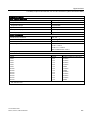
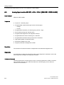
S7-300 Module data
___________________
Preface
1
___________________
General technical data
SIMATIC
S7-300
S7-300 Module data
2
___________________
Power supply modules
3
___________________
Digital modules
Principles of analog value
4
___________________
processing
5
___________________
Principles of analog modules
Manual
6
___________________
Analog modules
7
___________________
Other signal modules
8
___________________
Interface modules
Parameter sets of signal
A
___________________
modules
Diagnostics data of signal
modules
B
___________________
C
___________________
Dimensional drawings
Spare parts and accessories
for S7-300 modules
D
___________________
Directive on handling
Electrostatic-Sensitive
Devices (ESD)
E
___________
This description is part of the S7-300
documentation package with the order number:
6ES7398-8FA10-8AB0
02/2013
A5E00105505-08
F
Service & support
___________________
G
List of abbreviations
___________________
Legal information
Warning notice system
This manual contains notices you have to observe in order to ensure your personal safety, as well as to prevent
damage to property. The notices referring to your personal safety are highlighted in the manual by a safety alert
symbol, notices referring only to property damage have no safety alert symbol. These notices shown below are
graded according to the degree of danger.
DANGER
indicates that death or severe personal injury will result if proper precautions are not taken.
WARNING
indicates that death or severe personal injury may result if proper precautions are not taken.
CAUTION
indicates that minor personal injury can result if proper precautions are not taken.
NOTICE
indicates that property damage can result if proper precautions are not taken.
If more than one degree of danger is present, the warning notice representing the highest degree of danger will
be used. A notice warning of injury to persons with a safety alert symbol may also include a warning relating to
property damage.
Qualified Personnel
The product/system described in this documentation may be operated only by personnel qualified for the specific
task in accordance with the relevant documentation, in particular its warning notices and safety instructions.
Qualified personnel are those who, based on their training and experience, are capable of identifying risks and
avoiding potential hazards when working with these products/systems.
Proper use of Siemens products
Note the following:
WARNING
Siemens products may only be used for the applications described in the catalog and in the relevant technical
documentation. If products and components from other manufacturers are used, these must be recommended
or approved by Siemens. Proper transport, storage, installation, assembly, commissioning, operation and
maintenance are required to ensure that the products operate safely and without any problems. The permissible
ambient conditions must be complied with. The information in the relevant documentation must be observed.
Trademarks
All names identified by ® are registered trademarks of Siemens AG. The remaining trademarks in this publication
may be trademarks whose use by third parties for their own purposes could violate the rights of the owner.
Disclaimer of Liability
We have reviewed the contents of this publication to ensure consistency with the hardware and software
described. Since variance cannot be precluded entirely, we cannot guarantee full consistency. However, the
information in this publication is reviewed regularly and any necessary corrections are included in subsequent
editions.
Siemens AG
Industry Sector
Postfach 48 48
90026 NÜRNBERG
GERMANY
A5E00105505-08
Ⓟ 02/2013 Technical data subject to change
Copyright © Siemens AG 2013.
All rights reserved
Preface
Purpose of the manual
The information contained in this manual can be used as a reference to operating, to
functions, and to the technical data of the signal modules, power supply modules and
interface modules of the S7-300.
Refer to the relevant S7-300 or ET 200M manuals to find out how to assemble and wire the
modules.for system installation.
Basic knowledge required
This manual presumes general knowledge in the field of automation engineering.
Range of validity of this manual
The manual describes the components based on the data valid at the time of its release.
SIEMENS reserves the right to include product information for each new module of a later
version.
Changes compared to the previous version
Changes / enhancements compared to the previous version described in this manual:
● New digital input module SM 321 DI 16 x DC 24V/125V
6ES7321-7EH00-0AB0
● Errors in the previous version of this manual have been corrected in the present version.
S7-300 Module data
Manual, 02/2013, A5E00105505-08
3
Preface
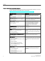
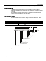
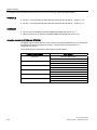
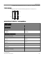
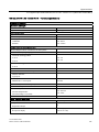
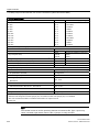
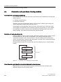
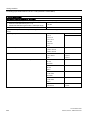
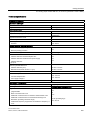
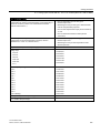
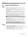
Position in the overall documentation structure
The following documentation forms part of the S7-300 documentation package. You can also
find this, along with the associated entry ID, on the Internet
(http://support.automation.siemens.com/WW/view/en/10805159/133300).
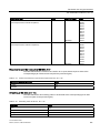
Name of the manual
Description
Manual
Control and display elements, communication,
memory concept, cycle and reaction times,
technical data
CPU 31xC and CPU 31x, technical data
Entry ID: 12996906
Operating Instructions
S7-300, CPU 31xC and CPU 31x: Installation
Entry ID: 13008499
Project design, installation, wiring, addressing,
commissioning, maintenance and test functions,
diagnostics and troubleshooting.
System Manual
Basic description of PROFINET:
PROFINET system description
Network components, data exchange and
communication, PROFINET IO, Componentbased Automation, application example of
PROFINET IO and Component-based
Automation.
Entry ID: 19292127
Programming Manual
Migration from PROFIBUS DP to PROFINET IO
Guideline for migration from PROFIBUS DP to
PROFINET IO.
Entry ID: 19289930
Manual
•
CPU 31xC: Technological functions
Entry ID: 12429336
•
CD containing examples
YOU ARE CURRENTLY READING the Manual
S7-300 Automation System: Module Data
Description of the technological functions:
positioning, counting, point-to-point coupling, loop
control.
The CD contains examples of the technological
functions.
Description of the functions and technical data of
signal/ power supply/ interface modules.
Entry ID: 8859629
Instructions List
•
CPU 31xC, CPU 31x,
IM151-7 CPU, IM154-8 CPU, BM 147-1 CPU,
BM 147-2 CPU
List of the CPU's instruction set and
corresponding execution times. List of executable
blocks (OBs, SFCs, SFBs) and their execution
times.
Entry ID: 13206730
•
CPU 312, CPU 314, CPU 315-2 DP
CPU 315-2 PN/DP, CPU 317-2 PN/DP,
CPU 319-3 PN/DP as of V3.0
Entry ID: 31977679
Getting Started
Available anthology of Getting Started manuals:
•
S7-300 Getting Started
Using concrete examples, the Getting Started
documentation provides step-by-step instructions
focused on commissioning a fully functional
application.
Entry ID: 15390497
•
PROFINET Getting Started Collection
Entry ID: 19290251
S7-300 Module data
4
Manual, 02/2013, A5E00105505-08
Preface
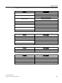
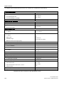
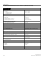
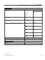
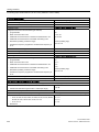
Other manuals on S7-300 and ET 200M
Name of the manual
Description
Reference Manual
Control and display elements, communication,
memory concept, cycle and reaction times,
technical data
•
CPU Data: CPU 312 IFM - 318-2 DP
•
Entry ID: 8860591
Software Installation Manual
S7-300 Automation System: Installation:
CPU 312 IFM – 318-2 DP
Project design, installation, wiring, addressing,
commissioning, maintenance and test functions,
diagnostics and troubleshooting.
Entry ID: 15390415
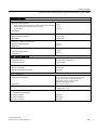
Configuration Manual
ET 200M signal modules for process automation
Entry ID: 7215812
Manual
Distributed I/O Device ET 200M
Description of integration in process automation,
parameter configuration using SIMATIC PDM,
digital input modules, digital output modules.
Description of configuration and commissioning
of HART analog modules.
HART analog modules
Entry ID: 22063748
Manual
Description of configuration, assembly and wiring.
Distributed I/O Device ET 200M
Entry ID: 1142798
Manual
SM 335 - High-speed analog mixed module for
SIMATIC S7-300
Entry ID: 1398483
Description of how to use the SM 335 module in
a SIMATIC S7-300.
Overview of operations, descriptions of functions,
and technical data relating to the SM 335.
Sign posts
The manual contains various features supporting quick access to specific information:
● At the beginning of the manual, you will find a complete table of contents.
● Key terms are explained in the glossary.
● You can use the index to find the key parts of the manual.
Approvals
See section Standards and approvals (Page 15).
CE approval
See section Standards and approvals (Page 15).
Mark for Australia (C-Tick-Mark)
See section Standards and approvals (Page 15).
S7-300 Module data
Manual, 02/2013, A5E00105505-08
5
Preface
Standards
See section Standards and approvals (Page 15).
Recycling and disposal
Since the S7-300 components only contain low levels of harmful substances, they are
suitable for recycling. For ecologically compatible recycling and disposal of your old device,
contact a certificated disposal service for electronic scrap.
Note on IT security
Siemens offers IT security mechanisms for its automation and drive product portfolio in order
to support the safe operation of the plant/machine. We recommend that you inform yourself
regularly on the IT security developments regarding your products. You can find information
on this on the Internet (http://support.automation.siemens.com).
You can register for a product-specific newsletter here.
For the safe operation of a plant/machine, however, it is also necessary to integrate the
automation components into an overall IT security concept for the entire plant/machine,
which corresponds to the state-of-the-art IT technology. You can find information on this on
the Internet (http://www.siemens.com/industrialsecurity).
Products used from other manufacturers should also be taken into account here.
S7-300 Module data
6
Manual, 02/2013, A5E00105505-08
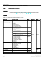
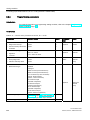
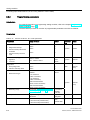
Table of contents
Preface ...................................................................................................................................................... 3
1
2
3
General technical data............................................................................................................................. 15
1.1
Standards and approvals .............................................................................................................15
1.2
Electromagnetic compatibility ......................................................................................................20
1.3
Shipping and storage conditions for modules and backup batteries ...........................................22
1.4
Mechanical and climatic environmental conditions for S7-300 operation....................................23
1.5
Specification of dielectric tests, protection class, degree of protection, and rated voltage
of S7-300......................................................................................................................................25
1.6
Rated voltages of S7-300 ............................................................................................................25
1.7
SIPLUS S7-300 Modules .............................................................................................................26
1.8
Environmental conditions for the operation of SIPLUS S7-300 modules ....................................29
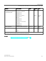
Power supply modules............................................................................................................................. 31
2.1
Power supply module PS 307; 2 A; (6ES7307-1BA01-0AA0).....................................................32
2.2
Power supply module PS 307; 5 A; (6ES7307-1EA01-0AA0).....................................................35
2.3
Power supply module PS 307; 10 A; (6ES7307-1KA02-0AA0)...................................................38
2.4
Power supply module PS 305; 2 A; (6AG1305-1BA80-2AA0) ....................................................41
2.5
Power supply module PS 307; 5 A; (6AG1307-1EA80-2AA0) ....................................................44
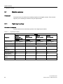
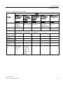
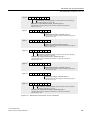
Digital modules ........................................................................................................................................ 49
3.1
3.1.1
3.1.2
3.1.3
3.1.4
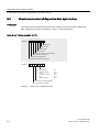
Module overview ..........................................................................................................................50
Digital input modules:...................................................................................................................50
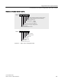
Digital output modules .................................................................................................................53
Relay output modules ..................................................................................................................56
Digital IO modules........................................................................................................................57
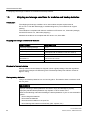
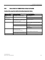
3.2
Steps in selecting and commissioning the digital module ...........................................................58
3.3
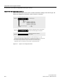
Programming digital modules ......................................................................................................59
3.4
Diagnostics of digital modules .....................................................................................................60
3.5
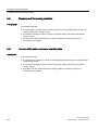
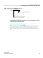
How to protect digital modules from inductive overvoltage .........................................................62
3.6
Digital input module SM 321; DI 64 x DC 24 V, sinking/sourcing; (6ES7321-1BP00-0AA0) ......64
3.7
Digital input module SM 321; DI 32 x DC 24 V; (6ES7321-1BL00-0AA0)...................................72
3.8
Digital output module SM 321; DI 32 x AC 120 V; (6ES7321-1EL00-0AA0)...............................76
3.9
Digital input module SM 321; DI 16 x DC 24 V; (6ES7321-1BH02-0AA0) ..................................79
3.10
Digital input module SM 321; DI 16 x DC 24 V High Speed; (6ES7321-1BH10-0AA0) ..............83
S7-300 Module data
Manual, 02/2013, A5E00105505-08
7
Table of contents
3.11
3.11.1
3.11.2
3.11.3
3.11.4
3.11.5
Digital input module SM 321; DI 16 x 24 VDC; with hardware and diagnostic interrupts
(6ES7321-7BH01-0AB0)............................................................................................................. 85
Isochronous mode....................................................................................................................... 90
SM 321; DI 16 x DC 24 V - Parameters...................................................................................... 91
SM 321; DI 16 x DC 24 V - Diagnostics...................................................................................... 93
SM 321; DI 16 x DC 24 V - Behavior .......................................................................................... 95
SM 321; DI 16 x DC 24 V - Interrupts ......................................................................................... 96
3.12.1
3.12.2
3.12.3
Digital input module SM 321; DI 16 x DC 24/125 V; with hardware and diagnostic
interrupts (6ES7321-7EH00-0AB0)............................................................................................. 98
Parameters of SM 321; DI 16 x DC 24/125 V ........................................................................... 102
Diagnostics of SM 321; DI 16 x DC 24/125 V ........................................................................... 103
Interrupts of SM 321; DI 16 x DC 24/125 V .............................................................................. 105
3.13
Digital input module SM 321; DI 16 x DC 24 V; source input; (6ES7321-1BH50-0AA0) ......... 107
3.14
Digital input module SM 321; DI 16 x UC 24/48 V; (6ES7321-1CH00-0AA0) .......................... 110
3.15
Digital input module SM 321; DI 16 x DC 48-125 V; (6ES7321-1CH20-0AA0)........................ 113
3.16
Digital input module SM 321; DI 16 x AC 120/230 V; (6ES7321-1FH00-0AA0)....................... 117
3.17
Digital input module SM 321; DI 8 x AC 120/230 V; (6ES7321-1FF01-0AA0) ......................... 120
3.18
Digital input module SM 321; DI 8 x AC 120/230 V ISOL; (6ES7321-1FF10-0AA0)................ 124
3.19
Digital output module SM 322; DO 64 x DC 24 V/0.3 A sourcing; (6ES7322-1BP00-0AA0) ... 127
3.20
Digital output module SM 322; DO 64 x DC 24 V/0.3 A Sinking (6ES7322-1BP50-0AA0) ...... 135
3.21
Digital output module SM 322; DO 32 x DC 24 V/ 0.5 A; (6ES7322-1BL00-0AA0) ................. 143
3.22
Digital output module SM 322; DO 32 x AC 120/230 V/1 A; (6ES7322-1FL00-0AA0)............. 147
3.23
Digital output module SM 322; DO 16 x DC 24 V/ 0.5 A; (6ES7322-1BH01-0AA0)................. 151
3.24
3.24.1
3.24.2
3.24.3
3.24.4
Digital output module SM 322; DO 16 x DC 24 V/0.5 A: (6ES7322-8BH10-0AB0).................. 155
Parameters of digital output modules ....................................................................................... 160
Diagnosis of digital output modules .......................................................................................... 161
Firmware update via HW Config ............................................................................................... 163
I&M identification data............................................................................................................... 164
3.25
Digital output module SM 322; DO 16 x DC 24 V/0.5 A High Speed;
(6ES7322-1BH10-0AA0)........................................................................................................... 165
3.26
3.26.1
Digital output module SM 322; DO 16 x UC 24/48 V; (6ES7322-5GH00-0AB0)...................... 169
Parameters of digital output module SM 322 DO 16 x UC24/48 V........................................... 173
3.27
Digital output module SM 322; DO 16 x AC 120/230 V/1 A; (6ES7322-1FH00-0AA0) ............ 175
3.28
Digital output module SM 322; DO 8 x DC 24 V/2 A; (6ES7322-1BF01-0AA0) ....................... 179
3.29
3.29.1
3.29.2
3.29.3
3.29.4
Digital output module SM 322; DO 8 x DC 24 V/ 0.5 A; with diagnostics interrupt;
(6ES7322-8BF00-0AB0) ........................................................................................................... 183
SM 322; DO 8 x DC 24 V/0.5 A - Parameters........................................................................... 188
SM 322; DO 8 x DC 24 V/0.5 A - Diagnostics........................................................................... 189
SM 322; DO 8 x DC 24 V/0.5 A - Behavior ............................................................................... 191
SM 322; DO 8 x DC 24 V/0.5 A - Interrupts .............................................................................. 192
3.30
Digital output module SM 322; DO 8 x DC 48-125 V/1.5 A; (6ES7322-1CF00-0AA0)............. 193
3.31
Digital output module SM 322;DO 8 x AC 120/230 V/2 A; (6ES7322-1FF01-0AA0)................ 197
3.12
S7-300 Module data
8
Manual, 02/2013, A5E00105505-08
Table of contents
3.32
3.32.1
3.32.2
3.32.3
Digital output module SM 322; DO 8 x AC 120/230 V/2 A ISOL (6ES7322-5FF00-0AB0) .......201
Parameters of SM 322; DO 8 x AC 120/230 V/2 A ISOL ..........................................................205
SM 322; DO 8 x AC 120/230 V/2 A ISOL - Diagnostics ............................................................206
SM 322; DO 8 x AC 120/230 V/2 A ISOL - Interrupts................................................................207
3.33
Relay output module SM 322; DO 16 x Rel. AC 120/230 V; (6ES7322-1HH01-0AA0) ............208
3.34
Relay output module SM 322; DO 8 x Rel. AC 230 V; (6ES7322-1HF01-0AA0)......................212
3.35
3.35.1
3.35.2
3.35.3
Relay output module SM 322; DO 8 x Rel. 230VAC/5A; (6ES7322-5HF00-0AB0) ..................217
Parameters of SM 322; DO 8 x Rel. AC 230V/5A .....................................................................223
SM 322; DO 8 x Rel. AC 230V/5A - Diagnostics .......................................................................224
SM 322; DO 8 x Rel. AC 230V/5A - Interrupts...........................................................................225
3.36
Relay output module SM 322; DO 8 x Rel. AC 230 V/5 A; (6ES7322-1HF10-0AA0) ...............226
3.37
Digital IO module SM 323; DI 16/DO 16 x DC 24 V/0.5 A; (6ES7323-1BL00-0AA0)................232
3.38
Digital IO module SM 323; DI 8/DO 8 x DC 24 V/0.5 A; (6ES7323-1BH01-0AA0) ...................236
3.39
Programmable digital IO module SM 327; DI 8/DO 8 x DC 24 V/0.5 A
(6ES7327-1BH00-0AB0)............................................................................................................240
3.39.1 Parameters of SM 327; DI 8/DO 8 x 24 VDC/0.5 A ...................................................................244
3.39.1.1 Structure of data record 1 of SM 327; DI 8/DO 8 x DC 24 V/0.5 A............................................245
4
5
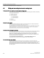
Principles of analog value processing.................................................................................................... 247
4.1
Overview ....................................................................................................................................247
4.2
4.2.1
4.2.2
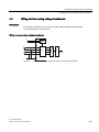
Wiring and connecting transducers to analog inputs.................................................................248
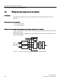
Wiring and connecting electrically isolated transducers ............................................................249
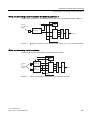
Wiring non-isolated transducers ................................................................................................251
4.3
Wiring and connecting voltage transducers...............................................................................253
4.4
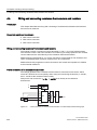
Wiring and connecting current transducers ...............................................................................254
4.5
Wiring and connecting resistance thermometers and resistors.................................................256
4.6
4.6.1
4.6.2
Wiring and connecting thermocouples.......................................................................................258
Wiring and connecting thermocouples with internal compensation...........................................262
Wiring and connecting thermocouples with external compensation..........................................263
4.7
4.7.1
4.7.2
Wiring and connecting loads/actuators to analog outputs .........................................................267
Wiring and connecting loads/actuators to voltage outputs ........................................................268
Wiring and connecting loads/actuators to current outputs.........................................................270
Principles of analog modules ................................................................................................................. 273
5.1
Representation of the values for analog input channels............................................................275
5.2
Representation of analog values for analog output channels....................................................292
5.3
Setting the measuring method and ranges of analog input channels........................................295
5.4
5.4.1
5.4.2
5.4.3
Response of the analog modules ..............................................................................................298
Influence of the power supply and operating state ....................................................................298
Influence of the range of analog values.....................................................................................300
Influence of operational limits and basic error limits ..................................................................301
5.5
Conversion and cycle times of analog modules ........................................................................302
5.6
Settling and response times of analog output channels ............................................................306
S7-300 Module data
Manual, 02/2013, A5E00105505-08
9
Table of contents
6
5.7
5.7.1
Programming analog modules .................................................................................................. 307
Parameters of analog input modules ........................................................................................ 308
5.8
5.8.1
5.8.2
5.8.3
5.8.4
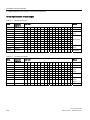
Diagnostics of analog modules ................................................................................................. 308
Diagnostics messages of analog input modules....................................................................... 309
Diagnostic messages of analog output modules ...................................................................... 310
Causes of error and troubleshooting at analog input modules ................................................. 311
Causes of error and troubleshooting at analog output modules ............................................... 312
5.9
Interrupts of analog modules .................................................................................................... 313
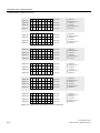
Analog modules ..................................................................................................................................... 315
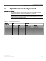
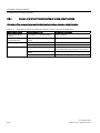
6.1
Analog module selection and commissioning sequence .......................................................... 316
6.2
6.2.1
6.2.2
6.2.3
Module overview ....................................................................................................................... 317
Analog input modules................................................................................................................ 317
Analog output modules ............................................................................................................. 320
Analog I/O modules................................................................................................................... 321
6.3
6.3.1
6.3.2
6.3.3
Analog input module SM 331; AI 8 x 16 bit; (6ES7331-7NF00-0AB0) ..................................... 322
Measurement types and ranges ............................................................................................... 328
Programmable parameters ....................................................................................................... 329
Additional information on SM 331; AI 8 x 16 Bit........................................................................ 331
6.4
6.4.1
6.4.2
6.4.3
Analog input module SM 331; AI 8 x 16 Bit; (6ES7331-7NF10-0AB0)..................................... 333
Measurement types and measuring ranges.............................................................................. 339
Programmable parameters ....................................................................................................... 340
Additional information for SM 331; AI 8 x 16 Bit ....................................................................... 341
6.5
6.5.1
6.5.2
6.5.3
6.5.4
Analog input module SM 331; AI 8 x 14 Bit High Speed; isochrone;
(6ES7331-7HF0x-0AB0) ........................................................................................................... 345
Measurement types and measuring ranges.............................................................................. 351
Programmable parameters ....................................................................................................... 353
Isochronous mode..................................................................................................................... 354
Additional information on SM 331; AI 8 x 14 Bit High Speed, isochrone.................................. 356
6.6
6.6.1
6.6.2
6.6.3
Analog input module SM 331; AI 8 x 13 Bit; (6ES7331-1KF02-0AB0) ..................................... 357
Measurement types and measuring ranges.............................................................................. 365
Programmable parameters ....................................................................................................... 366
Additional information on SM 331; AI 8 x 13 Bit........................................................................ 367
6.7
6.7.1
6.7.2
6.7.3
6.7.4
Analog input module SM 331; AI 8 x 12 bit;(6ES7331-7KF02-0AB0) ...................................... 370
Analog input module SM 331; AI 8 x 12 bit;(6ES7331-7KF02-0AB0) ...................................... 370
Measurement types and ranges ............................................................................................... 381
Programmable parameters ....................................................................................................... 384
Additional information on SM 331; AI 8 x 12 Bit........................................................................ 385
6.8
6.8.1
6.8.2
6.8.3
6.8.4
Analog input module SM 331; AI 2 x 12 Bit; (6ES7331-7KB02-0AB0)..................................... 386
Analog input module SM 331; AI 2 x 12 Bit; (6ES7331-7KB02-0AB0)..................................... 386
Measurement types and measuring ranges.............................................................................. 396
Programmable parameters ....................................................................................................... 398
Additional information on SM 331; AI 2 x 12 Bit........................................................................ 399
6.9
6.9.1
6.9.2
6.9.3
Analog input module SM 331; AI 8 x RTD; (6ES7331-7PF01-0AB0)....................................... 400
Measurement types and measuring ranges.............................................................................. 407
Programmable parameters ....................................................................................................... 410
Additional information on SM 331; AI 8 x RTD ......................................................................... 412
S7-300 Module data
10
Manual, 02/2013, A5E00105505-08
Table of contents
7
6.10
6.10.1
6.10.2
6.10.3
Analog input module SM 331; AI 8 x TC; (6ES7331-7PF11-0AB0) ..........................................416
Measurement types and measuring ranges ..............................................................................425
Adjustable parameters ...............................................................................................................426
Additional information on SM 331; AI 8 x TC.............................................................................428
6.11
6.11.1
6.11.2
6.11.3
6.11.4
6.11.5
6.11.6
Analog input module SM 331, AI 6 x TC isolated (6ES7331-7PE10-0AB0)..............................433
Measurement types and measuring ranges ..............................................................................444
Programmable parameters ........................................................................................................445
Additional information relating to SM 331; AI 6 x TC .................................................................446
Firmware update via HW Config for analog input module SM 331; AI 6 x TC ..........................453
I&M data for identifying the analog input module SM 331; AI 6 x TC ........................................455
Calibration of analog input module SM 331; AI 6 x TC..............................................................456
6.12
6.12.1
6.12.2
6.12.3
Analog output module SM 332; AO 8 x 12 bit; (6ES7332-5HF00-0AB0) ..................................463
SM 332; AO 8 x 12 Bit - Output ranges .....................................................................................468
Programmable parameters ........................................................................................................469
Additional information on SM 332; AO 8 x 12 Bit.......................................................................470
6.13
6.13.1
6.13.2
6.13.3
6.13.4
Analog output module SM 332; AO 4 x 16 bit; isochrone; (6ES7332-7ND02-0AB0) ................471
SM 332; AO 4 x 16 Bit - Output ranges .....................................................................................477
Programmable parameters ........................................................................................................478
Isochronous mode .....................................................................................................................479
Additional information on SM 332; AO 4 x 16 Bit.......................................................................480
6.14
6.14.1
6.14.2
6.14.3
Analog output module SM 332; AO 4 x 12 Bit; (6ES7332-5HD01-0AB0) .................................481
Output ranges of SM 332; AO 4 x 12 Bit ...................................................................................487
Programmable parameters ........................................................................................................488
Additional information on SM 332; AO 4 x 12 Bit.......................................................................489
6.15
6.15.1
6.15.2
6.15.3
Analog output module SM 332; AO 2 x 12 Bit; (6ES7332-5HB01-0AB0) .................................490
Output ranges of SM 332; AO 2 x 12 Bit ...................................................................................496
Programmable parameters ........................................................................................................497
Additional information on SM 332; AO 2 x 12 Bit.......................................................................498
6.16
6.16.1
6.16.2
6.16.3
6.16.4
Analog IO module SM 334; AI 4/AO 2 x 8/8 Bit; (6ES7334-0CE01-0AA0) ...............................499
SM 334; AI 4/AO 2 x 8/8 Bit - Function principle .......................................................................505
Measurement and output type of SM 334; AI 4/AO 2 x 8/8 bit ..................................................506
Measurement and output ranges of SM 334; AI 4/ AO 2 x 8/8 bit .............................................506
Additional information on SM 334; AI 4/AO2 x 8/8 Bit ...............................................................506
6.17
6.17.1
6.17.2
6.17.3
Analog IO module SM 334; AI 4/AO 2 x 12 bit; (6ES7334-0KE00-0AB0).................................507
Programmable parameters ........................................................................................................513
Measurement types and ranges ................................................................................................514
Additional information on SM 334; AI 4/ AO 2 x 12 bit ..............................................................515
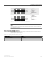
Other signal modules............................................................................................................................. 517
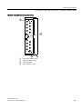
7.1
Module overview ........................................................................................................................517
7.2
Simulator module SM 374; IN/OUT 16; (6ES7374-2XH01-0AA0).............................................518
7.3
Dummy module DM 370; (6ES7370-0AA01-0AA0)...................................................................521
7.4
7.4.1
7.4.2
7.4.3
7.4.3.1
Position decoder module SM 338; POS-INPUT; (6ES7338-4BC01-0AB0) ..............................523
Isochronous mode .....................................................................................................................525
Wiring and block diagrams.........................................................................................................526
Functions of SM 338; POS-INPUT; encoder value acquisition .................................................527
Encoder value acquisition ..........................................................................................................527
S7-300 Module data
Manual, 02/2013, A5E00105505-08
11
Table of contents
7.4.3.2
7.4.3.3
7.4.3.4
7.4.4
7.4.5
7.4.6
7.4.7
7.4.8
8
A
B
Gray code/binary code converter.............................................................................................. 527
Transferred encoder value and scaling..................................................................................... 528
Freeze function ......................................................................................................................... 530
Parametrization SM 338 POS-INPUT....................................................................................... 530
Addressing SM 338 POS-INPUT .............................................................................................. 532
Diagnostics of SM 338; POS-INPUT ........................................................................................ 534
SM 338; POS INPUT - Interrupts.............................................................................................. 536
Technical data of SM 338; POS-INPUT.................................................................................... 537
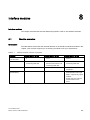
Interface modules .................................................................................................................................. 541
8.1
Module overview ....................................................................................................................... 541
8.2
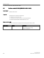
Interface module IM 360; (6ES7360-3AA01-0AA0).................................................................. 542
8.3
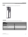
Interface module IM 361; (6ES7361-3CA01-0AA0).................................................................. 544
8.4
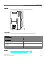
Interface module IM 365; (6ES7365-0BA01-0AA0).................................................................. 546
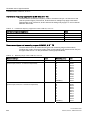
Parameter sets of signal modules.......................................................................................................... 549
A.1
Principles of programming signal modules in the user program............................................... 549
A.2
Parameters of digital IO modules.............................................................................................. 551
A.3
Parameters of the digital input module SM 321; DI 16 x DC 24/125 V..................................... 553
A.4
Parameters of digital output modules ....................................................................................... 555
A.5
Settings from the digital output module SM 322; DO 16 x DC 24 V/0.5 A
(6ES7322-8BH10-0AB0)........................................................................................................... 557
A.6
Parameters of analog input modules ........................................................................................ 560
A.7
Parameters of analog input module SM 331; AI 8 x RTD......................................................... 564
A.8
Parameters of SM 331; AI 8 TC ................................................................................................ 574
A.9
Parameters of analog input module SM 331; AI 8 x 13 Bit ....................................................... 582
A.10
Setting of the analog input module SM 331; AI 8 x 16 Bit (6ES7331-7NF10-0AB0) ................ 585
A.11
Parameters of analog input module SM 331; AI 6 x TC isolated .............................................. 592
A.12
Parameters of analog output modules ...................................................................................... 599
A.13
Parameters of analog output module SM 332; AO 8 x 12 Bit ................................................... 602
A.14
Parameters of analog IO modules ............................................................................................ 605
Diagnostics data of signal modules........................................................................................................ 609
B.1
Evaluating diagnostic data of signal modules in the user program........................................... 609
B.2
Structure and content of diagnostics data, byte 0 and up......................................................... 610
B.3
Channel-specific diagnostics data ............................................................................................ 614
B.4
Diagnosis data from the SM 322; DO 16 x DC24 V/0.5 A (6ES7322-8BH10-0AB0)................ 616
B.5
Diagnostics data of SM 331; AI 6 x TC isolated........................................................................ 619
B.6
Diagnostics data of SM 338; POS-INPUT ................................................................................ 622
S7-300 Module data
12
Manual, 02/2013, A5E00105505-08
Table of contents
C
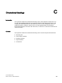
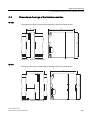
Dimensional drawings............................................................................................................................ 625
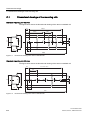
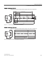
C.1
C.1.1
Dimensional drawings of the mounting rails ..............................................................................626
Bus modules ..............................................................................................................................632
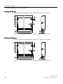
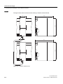
C.2
Dimensional drawings of the power supply modules.................................................................633
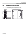
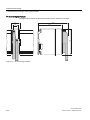
C.3
Dimensional drawings of the interface modules ........................................................................637
C.4
Dimensional drawings of the signal modules.............................................................................639
C.5
Dimensional drawings of accessories........................................................................................641
D
Spare parts and accessories for S7-300 modules ................................................................................. 643
E
Directive on handling Electrostatic-Sensitive Devices (ESD) ................................................................. 647
F
E.1
Definition of ESD........................................................................................................................647
E.2
Electrostatic charging of the body..............................................................................................648
E.3
Basic protective measures against electrostatic discharge .......................................................649
Service & support .................................................................................................................................. 651
F.1
G
Service & support.......................................................................................................................651
List of abbreviations............................................................................................................................... 653
G.1
List of abbreviations ...................................................................................................................653
Glossary ................................................................................................................................................ 655
Index...................................................................................................................................................... 665
S7-300 Module data
Manual, 02/2013, A5E00105505-08
13
Table of contents
S7-300 Module data
14
Manual, 02/2013, A5E00105505-08
General technical data
1.1
1
Standards and approvals
Introduction
Contents of general technical data:
● standards and test values satisfied by modules of the S7-300 automation system
● test criteria of S7-300 modules.
Note
Information on the nameplate
You will find the current labels and approvals on the nameplate of the respective
modules.
Safety guidelines
WARNING
Personal injury and damage to property may occur.
In potentially explosive environments, there is a risk of injury or damage if you disconnect
any connectors while the S7-300 is in operation.
Always isolate the S7-300 operated in such areas before you disconnect and connectors.
WARNING
Explosion hazard
Components may no longer qualify for Class I, Div. 2 if they are replaced.
WARNING
This S7-300 modules are only suitable for use in Class I, Div. 2, Group A, B, C, D, or in
non-hazardous areas.
S7-300 Module data
Manual, 02/2013, A5E00105505-08
15
General technical data
1.1 Standards and approvals
Test symbols and their significance
The test symbols and their meanings are described in the following section.
CE Label
The S7-300 automation system satisfies the requirements and protection goals of the
following EC directives, and conforms with the harmonized European standards (EN) for
programmable logic controllers announced in the Official Journals of the European
Community:
● 2006/95/EC "Electrical Equipment Designed for Use within Certain Voltage Limits"
(LowVoltage Directive)
● 2004/108/EC "Electromagnetic Compatibility" (EMC Directive)
● 94/9/EC "Equipment and protective systems intended for use in potentially explosive
atmospheres" (Explosion Protection Directive)
The EC declaration of conformity is held on file available to competent authorities at:
Siemens AG
Automation & Drives Group
Industry Sector I IA AS R&D DH A
P.O. Box 1963
92209 Amberg, Germany
You can also download this under the keyword "Declaration of conformity" on the Internet
(http://support.automation.siemens.com/WW/view/en/37217116/134200).
UL certification
Underwriters Laboratories Inc., complyling with
● UL 508 (Industrial Control Equipment)
S7-300 Module data
16
Manual, 02/2013, A5E00105505-08
General technical data
1.1 Standards and approvals
CSA approval
Canadian Standards Association to
● C22.2 No. 142 (Process Control Equipment)
or
cULus approval
Underwriters Laboratories Inc. complying with
● UL 508 (Industrial Control Equipment)
● CSA C22.2 No. 142 (Process Control Equipment)
or
cULus HAZ. LOC. - approval
+$=/2&
Underwriters Laboratories Inc., complying with
● UL 508 (Industrial Control Equipment)
● UL 1604 (Hazardous Location)
● CSA C22.2 No. 142 (Process Control Equipment)
● CSA C22.2 No. 213 (Hazardous Location)
APPROVED for use in
Class I, Division 2, Group A, B, C, D Tx;
Class I, Zone 2, Group IIC Tx
S7-300 Module data
Manual, 02/2013, A5E00105505-08
17
General technical data
1.1 Standards and approvals
FM approval
Factory Mutual Research (FM) in accordance with
Approval Standard Class Number 3611, 3600, 3810
APPROVED for use in
Class I, Division 2, Group A, B, C, D Tx;
Class I, Zone 2, Group IIC Tx
ATEX approval
In accordance with EN 60079-15 (Electrical Apparatus for Potentially Explosive
Atmospheres; Type of Protection "n") and EN 60079-0 (Electrical apparatus for potentially
explosive gas atmospheres - Part 0: General Requirements)
,,*([Q$,,77
Marking for Australia and New Zealand
The S7-300 automation system satisfies requirements of standards to
AS/NZS CISPR 16.
IEC 61131
The S7-300 automation system satisfies requirements and criteria to
IEC 61131-2 (Programmable Controllers, Part 2: Equipment requirements and tests).
S7-300 Module data
18
Manual, 02/2013, A5E00105505-08
General technical data
1.1 Standards and approvals
Marine approval
Classification societies:
● ABS (American Bureau of Shipping)
● BV (Bureau Veritas)
● DNV (Det Norske Veritas)
● GL (Germanischer Lloyd)
● LRS (Lloyds Register of Shipping)
● Class NK (Nippon Kaiji Kyokai)
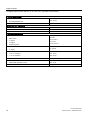
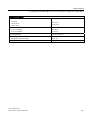
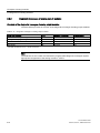
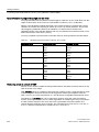
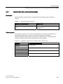
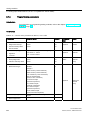
Use in industrial environments
SIMATIC products are designed for industrial applications.
Table 1- 1
Use in industrial environments
Field of application
Noise emission requirements
Noise immunity requirements
Industry
EN 61000-6-4: 2007
EN 61000-6-2: 2005
Use in residential areas
Note
The S7-300 is designed for use in industrial areas; using it in residential areas could disturb
radio and TV reception.
To operate an S7-300 in a residential area, it's RF emission must comply with Limit Value
Class B to EN 55011.
Suitable measures for achieving the required Class B radio interference level include, for
example:
● S7-300 installation in grounded switch cabinets / cubicles
● Use of noise filters in the supply lines
S7-300 Module data
Manual, 02/2013, A5E00105505-08
19
General technical data
1.2 Electromagnetic compatibility
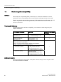
1.2
Electromagnetic compatibility
Definition
Electromagnetic compatibility (EMC) is the ability of an electrical installation to function
satisfactorily in its electromagnetic environment without interfering with that environment.
The S7-300 modules also satisfy requirements of EMC legislation for the European domestic
market. Compliance of the S7-300 system with specifications and directives on electric
design is prerequisite.
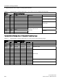
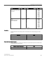
Pulseshaped disturbance
The table below shows the EMC compatibility of S7 modules in areas subject to pulseshaped disturbance.
Pulse-shaped disturbance
Electrostatic discharge
to IEC 61000-4-2
Burst pulses (high-speed
transient disturbance)
to IEC 61000-4-4.
Test voltage
corresponds with degree
of severity
Air discharge: ± 8 kV
3
Contact discharge ± 4 kV
2
2 kV (power supply lines)
2 kV (signal lines > 3 m)
1 kV (signal lines < 3 m)
3
3
High-energy single pulse (surge) to IEC 61000-4-5
External protective circuit required
(refer to S7-300 Automation System, Hardware and Installation,
Chapter "Lightning and overvoltage protection")
•
asymmetric coupling
2 kV (power supply lines)
DC with protective elements
3
2 kV (signal/ data line only > 3 m),
with protective elements as required
•
symmetric coupling
1 kV (power supply lines) DC with
protective elements
1 kV (signal/ data line only > 3 m),
with protective elements as required
Additional measures
When connecting an S7-300 system to the public network, always ensure compliance with
Limit Value Class B to EN 55022.
S7-300 Module data
20
Manual, 02/2013, A5E00105505-08
General technical data
1.2 Electromagnetic compatibility
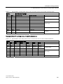
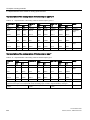
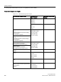
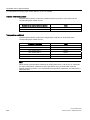
Sinusoidal disturbance
The table below shows the EMC compatibility of S7-300 modules in areas subject to
sinusoidal disturbance.
● HF radiation
HF radiation according to IEC 61000-4-3
corresponds to
degree of severity
Electromagnetic HF field, amplitude-modulated
80 MHz to 1,000 MHz; 1.4 GHz to 2 GHz
2.0 GHz to 2.7 GHz
10 V/m
1 V/m
3, 2, 1
80% AM (1 kHz)
● HF coupling
HF coupling according to IEC 61000-4-6
Corresponds with
degree of severity
3
0.15 MHz to 80 MHz
10 Vrms unmodulated
80% AM (1 kHz)
150 Ω source impedance
Emission of radio interference
Electromagnetic interference to EN 55016: Limit Value Class A (measured at a distance
of 10 m).
Frequency
Noise emission
30 MHz to 230 MHz
< 40 dB (µV/m)Q
230 MHz to 1000 MHz
< 47 dB (µV/m)Q
Noise emission via AC mains to EN 55016: Limit value class A, Group 1.
Frequency
Noise emission
From 0.15 to 0.5 MHz
< 79 dB (µV/m)Q
< 66 dB (µV/m)M
0.5 MHz to 5 MHz
< 73 dB (µV/m)Q
< 60 dB (µV/m)M
5 MHz to 30 MHz
< 73 dB (µV/m)Q
< 60 dB (µV/m)M
S7-300 Module data
Manual, 02/2013, A5E00105505-08
21
General technical data
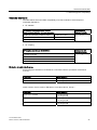
1.3 Shipping and storage conditions for modules and backup batteries
1.3
Shipping and storage conditions for modules and backup batteries
Introduction
The shipping and storage conditions of S7-300 modules surpass requirements to
IEC 61131-2. The data below apply to modules shipped or put on shelf in their original
packing.
The modules are compliant with climatic conditions to IEC 60721-3-3, Class 3K7 (storage),
and with IEC 60721-3-2, Class 2K4 (shipping.)
Mechanical conditions are compliant with IEC 60721-3-2, Class 2M2.
Shipping and storage conditions for modules
Type of condition
Permissible range
Free fall (in shipping package)
≤1m
Temperature
- 40 °C to + 70 °C
Barometric pressure
1080 hPa to 660 hPa
(corresponds with an altitude of -1000 m to 3500 m)
Relative humidity
10% to 95%, no condensation
Sinusoidal oscillation to
IEC 60068-2-6
5 Hz to 9 Hz: 3.5 mm
9 Hz to 150 Hz: 9.8 m/s2
Shock to IEC 60068-2-29
250 m/s2, 6 ms, 1000 shocks
Shipment of backup batteries
Backup batteries should always be shipped in their original package. Note the regulations
governing the transport of hazardous goods. The backup battery has a lithium content of
approx. 0.25 g.
Storing backup batteries
Always store backup batteries in a cool and dry place. The batteries have a maximum shelf
life of 5 years.
WARNING
Improper handling of backup batteries can result in injury and damage to property.
Improperly handled backup batteries may explode or cause severe burns.
Observe the following rules when handling the backup batteries of your S7-300 automation
system:
• Never charge the batteries
• Never heat the batteries
• Never throw the batteries in an open fire
• Never damage the batteries mechanically (drill, squeeze, etc.)
S7-300 Module data
22
Manual, 02/2013, A5E00105505-08
General technical data
1.4 Mechanical and climatic environmental conditions for S7-300 operation
1.4
Mechanical and climatic environmental conditions for S7-300
operation
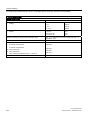
Operating conditions
S7-300 systems are designed for stationary use in weather-proof locations. The operating
conditions surpass requirements to DIN IEC 60721-3-3.
● Class 3M3 (mechanical requirements)
● Class 3K3 (climatic requirements)
Use with additional measures
The S7-300 may not be used under the conditions outlined below without taking additional
measures:
● at locations with a high degree of ionizing radiation
● in aggressive environments caused, for example, by
– the development of dust
– corrosive vapors or gases
– strong electric or magnetic fields
● in installations requiring special monitoring, for example
– elevators
– electrical plants in potentially hazardous areas
An additional measure could be an installation of the S7-300 in a cabinet or housing.
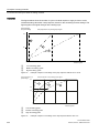
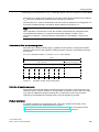
Mechanical environmental conditions
The table below shows the mechanical environmental conditions in the form of sinusoidal
oscillations.
Frequency band
Continuous
Infrequently
10 Hz ≤ f ≤ 58 Hz
0.0375 mm amplitude
0.75 mm amplitude
58 Hz ≤ f ≤ 150 Hz
0.5 g constant acceleration
1 g constant acceleration
Reducing vibrations
If your S7-300 modules are exposed to severe shock or vibration, take appropriate measures
to reduce acceleration or the amplitude.
We recommend the installation of the S7-300 on damping materials (for example, rubberbonded-to-metal mounting.)
S7-300 Module data
Manual, 02/2013, A5E00105505-08
23
General technical data
1.4 Mechanical and climatic environmental conditions for S7-300 operation
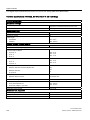
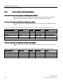
Test of mechanical environmental conditions
The table below provides important information with respect to the type and scope of the test
of ambient mechanical conditions.
Condition tested
Test Standard
Vibration
Vibration test to
Type of oscillation: Frequency sweeps with a rate of change of 1
IEC 60068-2-6 (sinusoidal) octave/minute.
Comment
5 Hz ≤ f ≤ 9 Hz, constant amplitude 3.5 mm
9 Hz ≤ f ≤ 150Hz, constant acceleration 1 g
Duration of oscillation: 10 frequency sweeps per axis at each of three
vertically aligned axes
Shock
Shock, tested to
IEC 60068-2-27
Type of shock: half-sine
Severity of shock: 15 g peak value, 11 ms duration
Direction of shock: 3 shocks in each direction (+/-) at each of three
vertically aligned axes
Climatic environmental conditions
The S7-300 may be operated on following environmental conditions:
Environmental conditions
Permitted range
Comments
Temperature:
horizontal mounting position:
vertical mounting position:
0°C to 60°C
0°C to 40°C
Relative humidity
10 % to 95 %
No condensation, corresponds to relative
humidity (RH) Class 2 to IEC 61131, Part 2
Barometric pressure
1080 hPa to 795 hPa
Corresponds with an altitude of -1000 m to
2000 m
Concentration of pollutants
SO2: < 0.5 ppm;
RH < 60 %, no condensation
H2S: < 0.1 ppm;
RH < 60 %, no condensation
Test: 10 ppm; 4 days
ISA-S71.04 severity level G1; G2; G3
-
-
Test: 1 ppm; 4 days
S7-300 Module data
24
Manual, 02/2013, A5E00105505-08
General technical data
1.5 Specification of dielectric tests, protection class, degree of protection, and rated voltage of S7-300
1.5
Specification of dielectric tests, protection class, degree of
protection, and rated voltage of S7-300
Test voltage
Proof of dielectric strength must be provided in the type test at a test voltage to IEC 61131-2:
Circuits with rated voltage Ve to other circuits or ground.
Test voltage
< 50 V
500 VDC
< 150 V
2500 VDC
< 250 V
4000 VDC
Protection class
Protection class I to IEC 60536, i.e., a protective conductor must be connected to the
mounting rail!
Protection against the ingress of foreign matter and water
● Degree of protection IP 20 to IEC 60529, i.e., protection against contact with standard
probes.
No protection against the ingress of water.
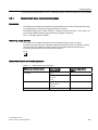
1.6
Rated voltages of S7-300
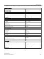
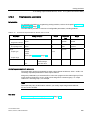
Rated operating voltages
The S7-300 modules operate at different rated voltages. The table shows the rated voltages
and corresponding tolerances.
Rated voltages
Tolerance
24 VDC
20.4 VDC to 28.8 VDC
120 VAC
93 VAC to 132 VAC
230 VAC
187 VAC to 264 VAC
S7-300 Module data
Manual, 02/2013, A5E00105505-08
25
General technical data
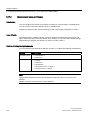
1.7 SIPLUS S7-300 Modules
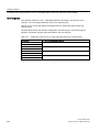
1.7
SIPLUS S7-300 Modules
Definition
SIPLUS S7-300 modules can be used under extended environmental conditions. Meaning of
"extended environmental conditions":
● Extended temperature range of - 25 °C to + 60 °C/70°C
● Moisture condensation/condensation permissible
● increased mechanical stress permissible
Comparison with "standard" modules
The functional scope and technical data of SIPLUS S7-300 modules and of "standard"
modules are identical, with the exception of the environmental conditions.
SIPLUS S7-300 modules have a separate order number (see the table below.)
The mechanical/climatic environmental conditions and the method of testing these have
changed. The SIPLUS S7-300 modules are specified:
● For deployment in harsh environmental conditions,
● For use in hostile environments.
● For extreme temperature ranges.
For more detailed information on this, refer to section Environmental conditions for the
operation of SIPLUS S7-300 modules (Page 29).
Project design in STEP 7
SIPLUS S7-300 modules are not included in the hardware catalog. Please design your plant
based on the relevant "standard" modules shown in the table below.
S7-300 Module data
26
Manual, 02/2013, A5E00105505-08
General technical data
1.7 SIPLUS S7-300 Modules
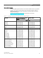
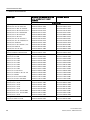
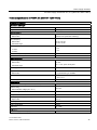
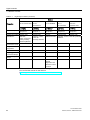
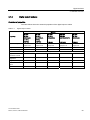
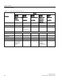
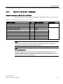
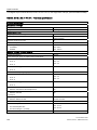
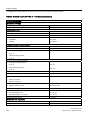
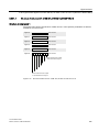
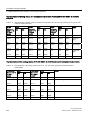
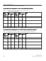
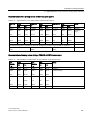
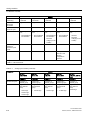
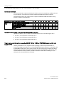
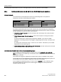
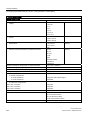
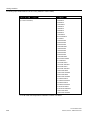
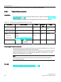
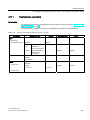
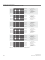
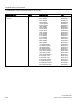
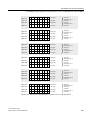
SIPLUS S7-300 Modules
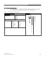
This following table contains all SIPLUS S7-300 modules available at the time of publication.
In addition, we included the order numbers of the corresponding "standard" modules to
support project design. You can refer to specifications and technical data in the special
"standard" module section.
You´ll find more information on SIPLUS and contact partners in the Internet
(http://www.siemens.com/siplus-extreme).
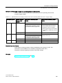
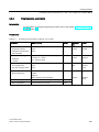
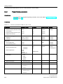
Table 1- 2
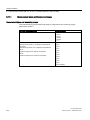
Comparison of SIPLUS S7-300 modules and S7-300 "Standard" module
Module type
SIPLUS S7-300 modules for the use
under extended environmental
conditions
"Standard" modules
as of order no.
Power supply
PS 305; 2A
6AG1305-1BA80-2AA0
6ES7305-1BA80-0AA0
PS 307; 5A
6AG1307-1EA80-2AA0
6ES7307-1EA80-0AA0
PS 307; 10A
6AG1307-1KA02-7AA0
6ES7307-1KA02-0AA0
IM 153-1
6AG1153-1AA03-2XB0
6ES7153-1AA03-0XB0
IM 365
6AG1365-0BA01-2AA0
6ES7365-0BA01-0AA0
Separator module
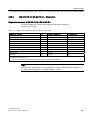
6AG1195-7KF00-2XA0
6ES7195-7KF00-0XA0
CPU 312C
6AG1312-5BE03-2AB0
6ES7312-5BE03-0AB0
CPU 313C
6AG1313-5BF03-2AB0
6ES7313-5BF03-0AB0
CPU 314
6AG1314-1AG14-7AB0
6ES7314-1AG14-0AB0
CPU 315–2 DP
6AG1315-2AH14-7AB0
6ES7315-2AH14-0AB0
CPU 313C-2DP
6AG1313-6CF03-2AB0
6ES7313-6CF03-0AB0
CPU 314C-2 PtP
6AG1314-6BG03-7AB0
6ES7314-6BG03-0AB0
CPU 314C-2DP
6AG1314-6CG03-2AB0
6ES7314-6CG03-0AB0
CPU 315-2PN/DP
6AG1315-2EH14-7AB0
6ES7315-2EH14-0AB0
CPU 317-2PN/DP
6AG1317-2EK13-2AB0
6ES7317-2EK13-0AB0
SM 321; DI 16 x DC 24V
6AG1321-1BH02-2AA0
6ES7321-1BH02-0AA0
SM 321; DI 32 x DC 24V
6AG1321-1BL00-2AA0
6ES7321-1BL00-0AA0
SM 321; DI 16 x DC 24V
6AG1321-7BH01-2AB0
6ES7321-7BH01-0AB0
SM 321; DI 8 x AC 120/230V
6AG1321-1FF10-7AA0
6ES7321-1FF10-0AA0
SM 321; DI 16 x DC 48 V-125V
6AG1321-1CH20-2AA0
6ES7321-1CH20-0AA0
SM 321; DI 8 x AC 120/220 V
6AG1321-1FF01-2AA0
6ES7321-1FF01-0AA0
SM 321; DI 4 NAMUR
6AG1321-7RD00-4AB0
6ES7321-7RD00-0AB0
SM 321; DI 16 x DC 24V
6AG1321-7TH00-4AB0
6ES7321-7TH00-0AB0
Interface module
Central module
Digital input module
S7-300 Module data
Manual, 02/2013, A5E00105505-08
27
General technical data
1.7 SIPLUS S7-300 Modules
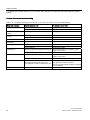
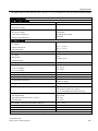
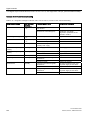
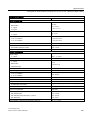
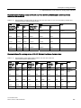
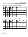
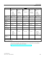
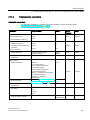
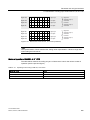
Module type
SIPLUS S7-300 modules for the use
under extended environmental
conditions
"Standard" modules
as of order no.
Digital output module
SM 322; DO 16 x DC 24V/0.5A
6AG1322-1BH01-2AA0
6ES7322-1BH01-0AA0
SM 322; DO 8 x Rel. AC 230V/5A
6AG1322-1HF10-2AA0
6ES7322-1HF10-0AA0
SM 322, DO 8 x DC 48-125 V/1.5 A
6AG1322-1CF00-7AA0
6ES7322-1CF00-0AA0
SM 322; DO 8 x AC 120/230V/2A
6AG1322-1FF01-7AA0
6ES7322-1FF01-0AA0
SM 322; DO 8 x DC 24V/0.5A
6AG1322-8BF00-2AB0
6ES7322-8BF00-0AB0
SM 322; DO 8 x DC 24V
6AG1322-1BF01-2XB0
6ES7322-1BF01-0AA0
SM 322; DO 32 x DC 24 V/0.5 A
6AG1322-1BL00-2AA0
6ES7322-1BL00-0AA0
SM 322; DO 16 x AC 120/230V/1 A
6AG1322-1FH00-7AA0
6ES7322-1FH00-0AA0
SM 322; DO 16 RELAY
6AG1322-1HH01-2AA0
6ES7322-1HH01-0AA0
SM 322; DO 8 x AC 120/230 V, 2 A
6AG1322-5FF00-4AB0
6ES7322-5FF00-0AB0
SM 322; DO 8 RELAY
6AG1322-5HF00-4AB0
6ES7322-5HF00-0AB0
SM 322; DO 16 x DC 24V
6AG1322-8BH01-2AB0
6ES7322-8BH01-0AB0
6AG1323-1BH01-2AA0
6ES7323-1BH01-0AA0
SM 331; AI 2 x 12Bit
6AG1331-7KB02-2AB0
6ES7331-7KB02-0AB0
SM 331; AI 8 x 13 Bit
6AG1331-1KF02-4AB0
6ES7331-1KF02-0AB0
SM 331; AI 8 x 13 Bit
6AG1331-1KF02-7AB0
6ES7331-1KF02-0AB0
SM 331; AI 8 x 12 Bit
6AG1331-7KF02-2AB0
6ES7331-7KF02-0AB0
SM 331; AI 8 x 16 Bit
6AG1331-7NF00-2AB0
6ES7331-7NF00-0AB0
SM 331; AI 8 x 16 Bit
6AG1331-7NF10-2AB0
6ES7331-7NF10-0AB0
SM 331; AI 8 x 13 Bit
6AG1331-7PF11-4AB0
6ES7331-7PF11-0AB0
SM 331; AI 4 x 0/4-20 mA
6AG1331-7RD00-2AB0
6ES7331-7RD00-0AB0
SM 331; AI 8 Thermo / AI 4 PT 100
6AG1331-7SF00-4AB0
6ES7331-7SF00-0AB0
SM 331; AI 2 HART
6AG1331-7TB00-7AB0
6ES7331-7TB00-0AB0
SM 331; AI 8 x 0 to 20mA HART
6AG1331-7TF01-4AB0
6ES7331-7TF01-0AB0
SM 331; AI 8 x 0/4 to mA HART
6AG1331-7TF01-7AB0
6ES7331-7TF01-0AB0
SM 332; AO 2 x 12 bit
6AG1332-5HB01-2AB0
6ES7332-5HB01-0AB0
SM 332; AO 4 x 12 bit
6AG1332-5HD01-7AB0
6ES7332-5HD01-0AB0
SM 332; AO 8 x 12 bit
6AG1332-5HF00-2AB0
6ES7332-5HF00-0AB0
SM 332; AO 8 x 12 bit
6AG1332-5HF00-4AB0
6ES7332-5HF00-0AB0
SM 332; AO 8 x 0/4 - 20 mA HART
6AG1332-8TF01-2AB0
6ES7332-8TF01-0AB0
SM 332; AO 8 x 0/4 - 20 mA HART
6AG1332-8TF01-4AB0
6ES7332-8TF01-0AB0
SM 332; AO 4 x 16 bit
6AG1332-7ND02-4AB0
6ES7332-7ND02-0AB0
6AG1334-0KE00-7AB0
6ES7334-0KE00-0AB0
Digital I/O module
SM 323; DI8/DO8 x DC 24V/0.5A
Analog input module
Analog output module
Analog IO module
SM 334; AI 4/AO 2 x 12 Bit
S7-300 Module data
28
Manual, 02/2013, A5E00105505-08
General technical data
1.8 Environmental conditions for the operation of SIPLUS S7-300 modules
1.8
Environmental conditions for the operation of SIPLUS S7-300
modules
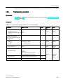
Mechanical environmental conditions
Operating category: to IEC 721 -3-3, Class 3M4.
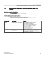
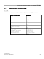
Test of mechanical environmental conditions
The table provides information on the type and scope of the test of mechanical
environmental conditions for SIPLUS S7-300 modules.
Table 1- 3
SIPLUS S7-300 Modules: Test of mechanical environmental conditions
Condition tested
Test Standard
Remarks
Vibration
Vibration test acc. to IEC 60068-2-6
(sinusoidal)
Type of oscillation: Frequency sweep at a
rate of change of 1 octave/minute.
5 Hz ≤ f ≤ 9 Hz, constant Amplitude 3.5 mm
9 Hz ≤ f ≤ 150 Hz, constant Acceleration
1 g duration of oscillation:
10 frequency sweeps at each of
three vertically aligned axes
Shock
Shock, tested acc. to
Type of shock: Half-sine
IEC 60068-2-27
Severity of shock: 15 g peak value, 11 ms duration
Direction of shock: 3 shocks each in +/– direction in each
of the three vertically aligned axes
S7-300 Module data
Manual, 02/2013, A5E00105505-08
29
General technical data
1.8 Environmental conditions for the operation of SIPLUS S7-300 modules
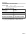
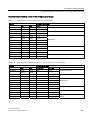
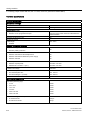
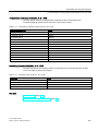
Environmental conditions
Operating category: to IEC 721 -3-3, Class 3K5.
The SIPLUS S7-300 modules may also be used under the following climatic, chemical,
biological and mechanical environmental conditions:
Table 1- 4
SIPLUS S7-300 Modules: Environmental conditions
Environmental conditions
Permitted range
Temperature:
Horizontal mounting position:
-25 °C to +60 °C/70°C
Vertical mounting position:
0°C to +40 °C
Relative humidity
5 ... 100%, moisture consdensation/condensation permissible
Resistance against biologically active substances
Conformity with EN 60721-3-3, Class 3B2 mildew, fungi and
sponge spores (excluding fauna)
Resistance against chemically active substances
Conformity with EN 60721-3-3, Class 3C4 incl. salt mist and
ISA –S71.04 severity level G1; G2; G3; GX 1)2)
Resistance against mechanically active substances
Conformity with EN 60721-3-3, Class 3S4 incl. conductive
sand, dust 2)
Air pressure in relation to
ambient temperature - air pressure - installation altitude
- 25 ... +60/70 °C at 1080 to 795 hPa ≙ -1000 to +2000 m
- 25 ... +50/60°C at 795 to 658 hPa ≙ +2000 to +3500 m
- 25 ... +40/50°C at 658 to 540 hPa ≙ +3500 to +5000 m
Certificate of suitability as approval for rail application
--> Partly EN 50155 T1 Cat1 Cl A/B
1)
ISA –S71.04 severity level GX: Dauerbelastung/long-term load: SO2 < 4.8 ppm; H2S < 9.9 ppm; Cl < 0.2 ppm;
HCl < 0.66 ppm; HF < 0.12 ppm; NH < 49 ppm; O3 < 0.1 ppm; NOX < 5.2 ppm
limit value (max. 30 min/d): SO2 < 14.8 ppm; H2S < 49.7 ppm; Cl < 1.0 ppm; HCl < 3.3 ppm; HF < 2.4 ppm;
NH < 247 ppm; O3 < 1.0 ppm; NOX < 10.4 ppm
2)
When operated in harmful gas environments, the supplied plug covers must remain on the non-used port.
S7-300 Module data
30
Manual, 02/2013, A5E00105505-08
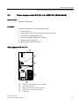
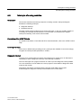
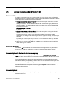
Power supply modules
2
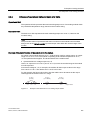
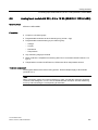
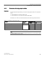
Introduction
Various 24-VDC power supply modules are available for your S7-300 PLC and the
sensors/actuators.
Power supply modules
This chapter contains the technical data of the S7-300 power supply modules.
In addition to technical data, this chapter describes:
● The characteristics
● Wiring diagram
● Block Diagram
● Line protection
● Reaction to atypical operating conditions
S7-300 Module data
Manual, 02/2013, A5E00105505-08
31
Power supply modules
2.1 Power supply module PS 307; 2 A; (6ES7307-1BA01-0AA0)
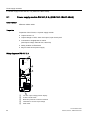
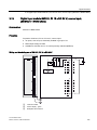
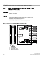
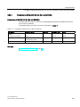
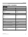
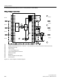
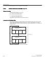
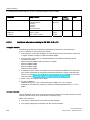
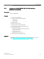
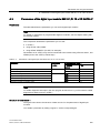
2.1
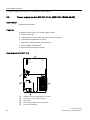
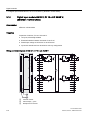
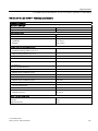
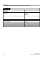
Power supply module PS 307; 2 A; (6ES7307-1BA01-0AA0)
Order number
6ES7307-1BA01-0AA0
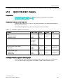
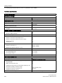
Properties
Properties of the PS 307; 2 A power supply module:
● Output current 2 A
● Output voltage 24 VDC; short circuit-proof, open circuit-proof
● Connection to singlephase AC mains
(rated input voltage 120/230 VAC, 50/60 Hz)
● Safety isolation to EN 60 950
● May be used as load power supply
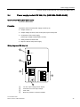
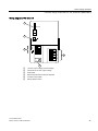
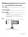
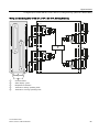
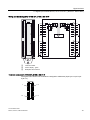
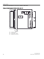
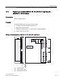
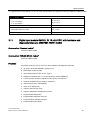
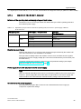
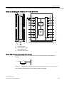
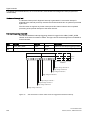
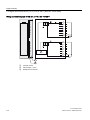
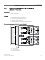
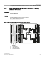
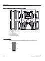
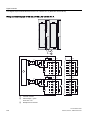
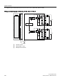
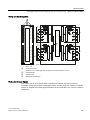
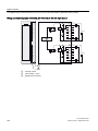
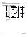
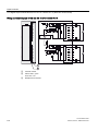
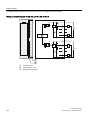
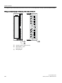
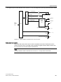
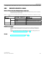
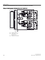
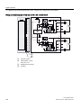
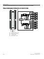
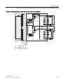
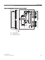
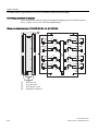
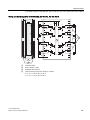
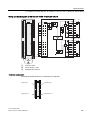
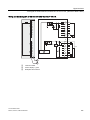
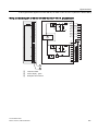
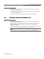
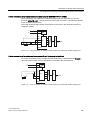
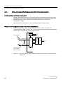
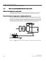
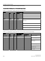
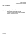
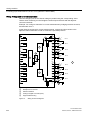
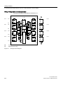
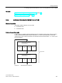
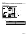
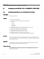
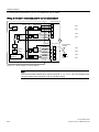
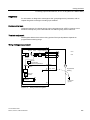
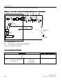
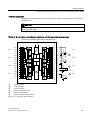
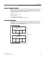
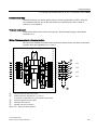
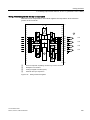
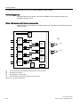
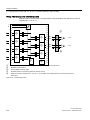
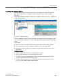
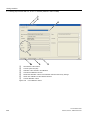
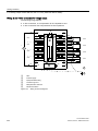
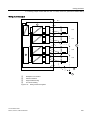
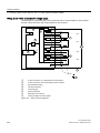
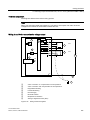
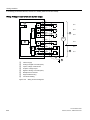
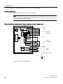
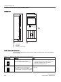
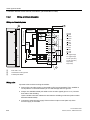
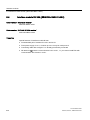
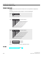
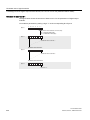
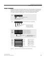
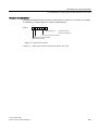
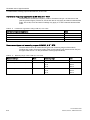
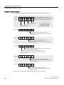
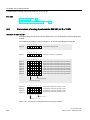
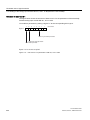
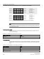
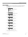
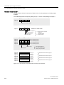
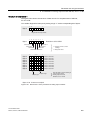
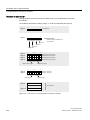
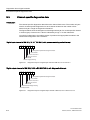
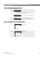
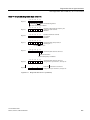
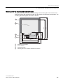
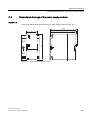
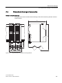
Wiring diagram of PS 307; 2 A
1
36
$
'&9
2
3
/ 1
<68;;
; /
0
/
0
4
5
①
②
③
④
⑤
"24 VDC output voltage present" display
24 VDC On/Off switch
Mains and protective conductor terminals
Terminals for 24 VDC output voltage
Strain-relief
S7-300 Module data
32
Manual, 02/2013, A5E00105505-08
Power supply modules
2.1 Power supply module PS 307; 2 A; (6ES7307-1BA01-0AA0)
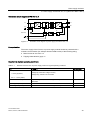
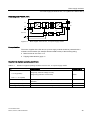
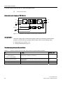
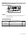
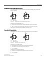
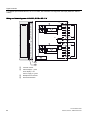
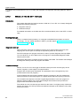
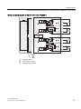
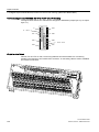
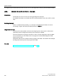
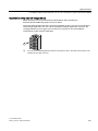
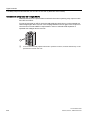
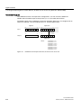
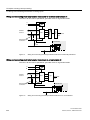
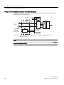
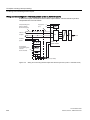
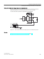
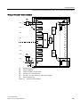
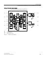
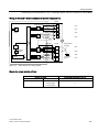
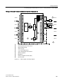
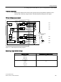
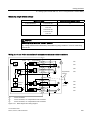
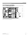
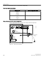
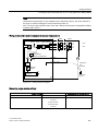
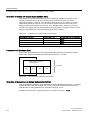
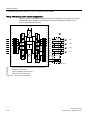
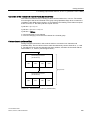
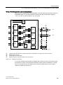
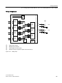
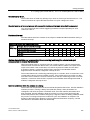
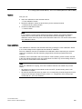
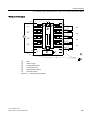
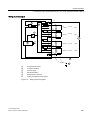
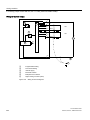
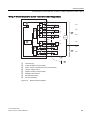
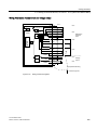
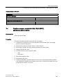
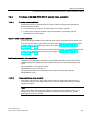
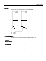
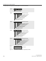
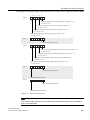
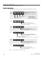
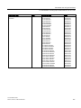
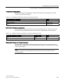
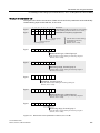
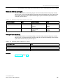
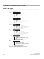
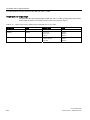
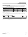
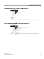
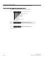
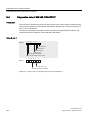
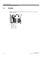
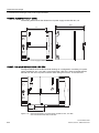
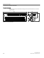
Schematic circuit diagram of PS 307; 2 A
/
/
1
0
8
'&9
Figure 2-1
Schematic circuit diagram of power supply module PS 307; 2 A
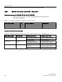
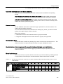
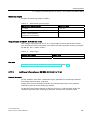
Line protection
The mains supply of the PS 307; 2A power supply module should be protected with a
miniature circuit-breaker (for example Siemens 5SN1 series) of the following rating:
● Rated current at 230 VAC: 3 A
● Tripping characteristics (type): C.
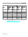
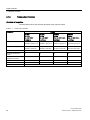
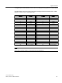
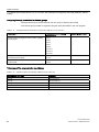
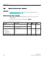
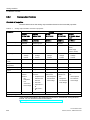
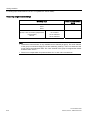
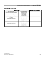
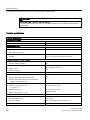
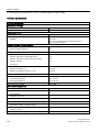
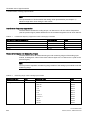
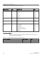
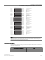
Reaction to atypical operating conditions
Table 2- 1
Reaction of the PS 307; 2A power supply module to atypical operating conditions
If ...
... then ...
Flashing
the output circuit is overloaded:
•
I > 2.6 A (dynamic)
•
2 A < I ≤ 2.6 A (static)
24 VDC LED
Voltage dip, automatic voltage recovery
Voltage drop, reduction of service life
short-circuit at the output
Output voltage 0 V; automatic voltage recovery after short-circuit is
eliminated
off
overvoltage on primary side
risk of destruction
-
undervoltage on primary side
Automatic shutdown; automatic voltage recovery
off
S7-300 Module data
Manual, 02/2013, A5E00105505-08
33
Power supply modules
2.1 Power supply module PS 307; 2 A; (6ES7307-1BA01-0AA0)
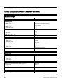
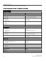
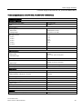
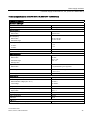
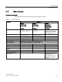
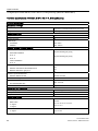
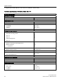
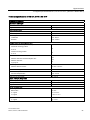
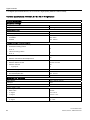
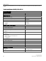
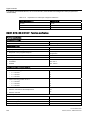
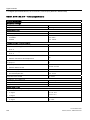
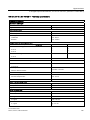
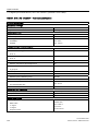
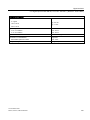
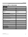
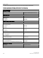
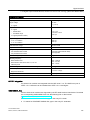
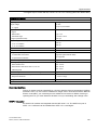
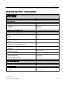
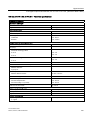
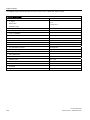
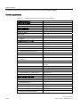
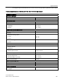
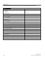
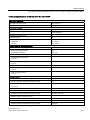
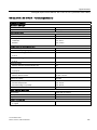
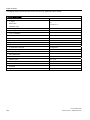
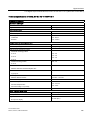
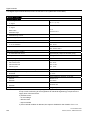
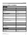
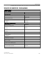
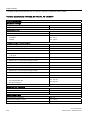
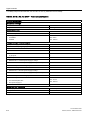
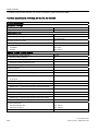
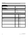
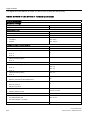
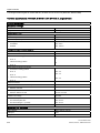
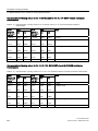
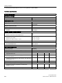
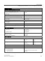
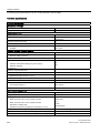
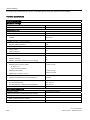
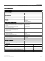
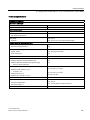
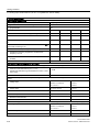
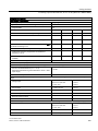
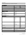
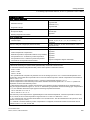
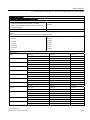
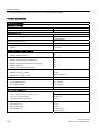
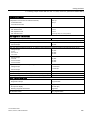
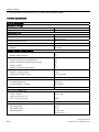
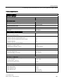
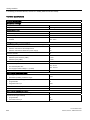
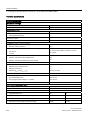
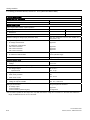
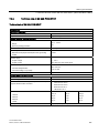
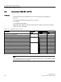
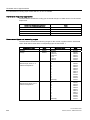
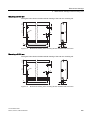
Technical specifications of the PS 307; 2 A (6ES7307-1BA01-0AA0)
Technical specifications
Dimensions and weight
Dimensions W x H x D (mm)
40 x 125 x 120
Weight
ca. 400 g
Input parameters
Input voltage
• Rated value
Mains frequency
•
Rated value
•
Permitted range
120/230 VAC (automatic switching)
50 Hz or 60 Hz
47 Hz to 63 Hz
Rated input current
•
at 230 V
•
at 120 V
0.5 A
0.9 A
Inrush current (at 25 °C)
22 A
I2 t
1 A2s
(at inrush current)
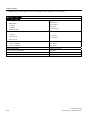
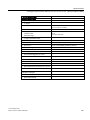
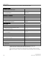
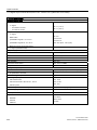
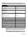
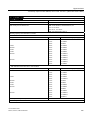
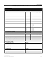
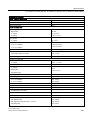
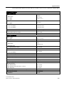
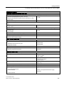
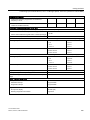
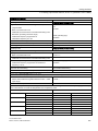
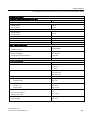
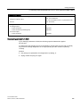
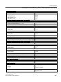
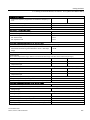
Output parameters
Output voltage
•
Rated value
•
Permitted range
•
Rampup time
24 VDC
24 V ± 3 %, open circuit-proof
max. 2.5 s
Output current
•
Rated value
2 A,
parallel wiring supported
Short-circuit protection
electronic, non-latching
1.1 to 1.3 x IN
Residual ripple
max. 150 mVpp
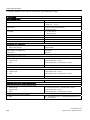
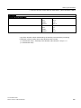
Characteristics
Safety class to IEC 536 (DIN VDE 0106, Part 1)
I, with protective conductor
Isolation rating
•
Rated isolation voltage
(24 V to L1)
•
Test voltage
AC 250 V
DC 4200 V
Safety isolation
SELV circuit
Buffering of power supply failure (at 93 V or 187 V)
min. 20 ms
•
Repeat rate
min 1 s
Efficiency
84 %
Power consumption
57 W
Power loss
Typ. 9 W
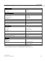
Diagnostics
"Output voltage present" display
yes, green LED
S7-300 Module data
34
Manual, 02/2013, A5E00105505-08
Power supply modules
2.2 Power supply module PS 307; 5 A; (6ES7307-1EA01-0AA0)
2.2
Power supply module PS 307; 5 A; (6ES7307-1EA01-0AA0)
Order number
6ES7307-1EA01-0AA0
Properties
Properties of the PS 307; 5 A power supply module:
● Output current 5 A
● Output voltage 24 VDC; short circuit-proof, open circuit-proof
● Connection to singlephase AC mains
(rated input voltage 120/230 VAC, 50/60 Hz)
● Safety isolation to EN 60 950
● May be used as load power supply
Wiring diagram of PS 307; 5 A
1
36
$
'&9
2
3
; <68;;
/ 1
/
0
/
0
/
0
4
5
①
②
③
④
⑤
Display for "Output voltage DC 24 V present"
24 VDC On/Off switch
Mains and protective conductor terminals
Terminals for 24 VDC output voltage
Strain-relief
S7-300 Module data
Manual, 02/2013, A5E00105505-08
35
Power supply modules
2.2 Power supply module PS 307; 5 A; (6ES7307-1EA01-0AA0)
Block diagram PS 307; 5 A
/
/
1
0
8
'&9
Figure 2-2
Block diagram of the PS 307; 5 A power supply module
Line protection
The mains supplies of the PS 307; 5 A power supply module should be protected with a
miniature circuit-breaker (for example Siemens 5SN1 series) of the following rating:
● Rated current at 230 VAC: 6 A
● Tripping characteristics (type): C.
Reaction to atypical operating conditions
Table 2- 2
Reaction to atypical operating conditions of the PS 307; 5 A power supply module
If ...
... then ...
DisplayDC 24 V
Voltage dip, automatic voltage recovery
flashes
the output circuit is overloaded:
•
I > 6.5 A (dynamic)
•
5 A < I ≤ 6.5 A (static)
Voltage drop, reduction of service life
short-circuit at the output
Output voltage 0 V; automatic voltage recovery after short-circuit is
eliminated
off
overvoltage on primary side
risk of destruction
-
undervoltage on primary side
Automatic shutdown; automatic voltage recovery
off
S7-300 Module data
36
Manual, 02/2013, A5E00105505-08
Power supply modules
2.2 Power supply module PS 307; 5 A; (6ES7307-1EA01-0AA0)
Technical specifications of PS 307; 5 A (6ES7307-1EA01-0AA0)
Technical specifications
Dimensions and weight
Dimensions W x H x D (mm)
60 x 125 x 120
Weight
ca. 600 g
Input parameters
Input voltage
•
Rated value
120/230 VAC (automatic switching)
Mains frequency
•
Rated value
•
Permitted range
50 Hz or 60 Hz
47 Hz to 63 Hz
Rated input current
•
at 120 V
•
at 230 V
2.3 A
1.2 A
Inrush current (at 25 °C)
20 A
I2 t
1.2 A2s
(at inrush current)
Output parameters
Output voltage
•
Rated value
•
Permitted range
•
Rampup time
24 VDC
24 V ± 3 %, open circuit-proof
max. 2.5 s
Output current
•
Rated value
Short-circuit protection
5 A, parallel wiring is available
electronic, non-latching
1.1 to 1.3 x IN
Residual ripple
max. 150 mVpp
Characteristics
Safety class to IEC 536 (DIN VDE 0106, Part 1)
I, with protective conductor
Isolation rating
•
Rated isolation voltage (24 V to L1)
250 VAC
•
Test voltage
4200 VDC
Safety isolation
SELV circuit
Buffering of power supply failure (at 93 V or 187 V)
Min. 20 ms
•
Repeat rate
min 1 s
Efficiency
87 %
Power consumption
138 W
Power loss
typ. 18 W
Diagnostics
"Output voltage present" display
yes, green LED
S7-300 Module data
Manual, 02/2013, A5E00105505-08
37
Power supply modules
2.3 Power supply module PS 307; 10 A; (6ES7307-1KA02-0AA0)
2.3
Power supply module PS 307; 10 A; (6ES7307-1KA02-0AA0)
Order number
6ES7307-1KA02-0AA0
Properties
Properties of the PS 307; 10 A power supply module:
● Output current 10 A
● Output voltage 24 VDC; short circuit-proof, open circuit-proof
● Connection to singlephase AC mains
(rated input voltage 120/230 VAC, 50/60 Hz)
● Safety isolation to EN 60 950
● May be used as load power supply
Block diagram of PS 307; 10 A
1
36
$
'&9
5
; <68;;
/
0
/ 1
/
0
4
/
2
0
/
0
3
①
②
③
④
⑤
Display for "Output voltage DC 24 V present"
Terminals for 24 VDC output voltage
Strain-relief
Mains and protective conductor terminals
24 VDC On/Off switch
S7-300 Module data
38
Manual, 02/2013, A5E00105505-08
Power supply modules
2.3 Power supply module PS 307; 10 A; (6ES7307-1KA02-0AA0)
Block diagram PS 307; 10 A
/
/
1
0
8
'&9
Figure 2-3
Block diagram of the PS 307; 10 A power supply module
Line protection
The mains supplies of the PS 307;10 A power supply module should be protected with a
miniature circuit-breaker (for example Siemens 5SN1 series) of the following rating:
● Rated current at 230 VAC: 10 A
● Tripping characteristics (type): C.
Reaction to atypical operating conditions
Table 2- 3
Reaction to atypical operating conditions of the PS 307; 10 A power supply module
If ...
Module reaction
DisplayDC 24 V
.output circuit is overloaded:
•
I > 13 A (dynamic)
•
10 A < I ≤ 13 A (static)
Voltage dip, automatic voltage recovery
Voltage drop (reduction of service life)
flashes
short-circuit at the output
Output voltage 0 V; automatic voltage recovery after short-circuit is
eliminated
off
overvoltage on primary side
risk of destruction
-
undervoltage on primary side
Automatic shutdown; automatic voltage recovery
off
S7-300 Module data
Manual, 02/2013, A5E00105505-08
39
Power supply modules
2.3 Power supply module PS 307; 10 A; (6ES7307-1KA02-0AA0)
Technical specifications of PS 307; 10 A (6ES7307-1KA02-0AA0)
Technical specifications
Dimensions and weight
Dimensions W x H x D (mm)
80 x 125 x 120
Weight
800 g
Input parameters
Input voltage
•
Rated value
120/230 VAC (automatic switching)
Mains frequency
•
Rated value
•
Permitted range
50 Hz or 60 Hz
47 Hz to 63 Hz
Rated input current
•
at 230 V
•
at 120 V
1.9 A
4.2 A
Inrush current (at 25 °C)
55 A
I2 t
3.3 A2s
(at inrush current)
Output parameters
Output voltage
•
Rated value
•
Permitted range
•
Rampup time
24 VDC
24 V ± 3 %, open circuit-proof
max. 2.5 s
Output current
•
Rated value
Short-circuit protection
10 A, parallel wiring is available
electronic, non-latching
1.1 to 1.3 x IN
Residual ripple
max. 150 mVpp
Characteristics
Safety class to IEC 536 (DIN VDE 0106, Part 1)
I, with protective conductor
Isolation rating
•
Rated isolation voltage (24 V to L1)
•
Test voltage
AC 250 V
DC 4200 V
Safety isolation
SELV circuit
Buffering of power supply failure (at 93 V or 187 V)
Min. 20 ms
•
Repeat rate
min 1 s
Efficiency
90 %
Power consumption
267 W
Power loss
typ. 27 W
Diagnostics
"Output voltage present" display
yes, green LED
S7-300 Module data
40
Manual, 02/2013, A5E00105505-08
Power supply modules
2.4 Power supply module PS 305; 2 A; (6AG1305-1BA80-2AA0)
2.4
Power supply module PS 305; 2 A; (6AG1305-1BA80-2AA0)
Order number "SIPLUS S7-300 module"
6AG1305-1BA80-2AA0
Properties
Properties of the PS 305 power supply module (2 A):
● Output current 2 A
● Output voltage 24 VDC; short circuit-proof, open circuit-proof
● Connection to DC power supply
(rated input voltage 24/48/72/96/110 VDC)
● Safety isolation to EN 60 950
● May be used as load power supply
Wiring diagram of PS 305; 2 A
'&9
/
0
/
0
/
0
/
0
①
②
③
④
"24 VDC output voltage present" display
Terminals for 24 VDC output voltage
Strain relief
Mains and protective conductor terminals
S7-300 Module data
Manual, 02/2013, A5E00105505-08
41
Power supply modules
2.4 Power supply module PS 305; 2 A; (6AG1305-1BA80-2AA0)
⑤
24 VDC On/Off switch
Schematic circuit diagram of PS 305; 2 A
/
/
0
0
8
'&9
Figure 2-4
Schematic circuit diagram of power supply module PS 305; 2 A
Line protection
The mains supply of the PS 305 power supply module (2 A) should be protected with a
miniature circuit-breaker (for example Siemens 5SN1 series) of the following rating:
● Rated current at 110 VDC: 10 A
● Tripping characteristics (type): C.
Reaction to atypical operating conditions
Table 2- 4
Reaction of the PS 305;(2 A) power supply module to atypical operating conditions
If ...
... then ...
24 VDC LED
... the output circuit is overloaded:
Voltage dip, automatic voltage recovery
Flashing
•
I > 3.9 A (dynamic)
•
3 A < I ≤ 3.9 A (static)
Voltage drop, reduction of service life
... short-circuit at the output
Output voltage 0 V; automatic voltage recovery after short-circuit off
is eliminated
overvoltage on primary side
risk of destruction
-
undervoltage on primary side
Automatic shutdown; automatic voltage recovery
off
S7-300 Module data
42
Manual, 02/2013, A5E00105505-08
Power supply modules
2.4 Power supply module PS 305; 2 A; (6AG1305-1BA80-2AA0)
Technical specifications of the PS 305; 2 A (6AG1305-1BA80-2AA0)
Technical specifications
Dimensions and weight
Dimensions W x H x D (mm)
80 x 125 x 120
Weight
ca. 740 g
Input parameters
Input voltage
•
Rated value
24/48/72/96/110 VDC
•
Voltage range
16.8 VDC to 138 VDC
Rated input current
•
at 24 V
•
at 48 V
•
at 72 V
•
at 96 V
•
at 110 V
2.7 A
1.3 A
0.9 A
0.65 A
0.6 A
Inrush current (at 25 °C)
20 A
I2 t
5 A2s
(at inrush current)
Output parameters
Output voltage
•
Rated value
•
Permitted range
•
Rampup time
Output current
•
Rated value
24 VDC
24 V ± 3 %, open circuit-proof
max. 3 s
2 A; 1)
parallel connection supported
Short-circuit protection
electronic, non-latching, 1.65 to 1.95 x IN
Residual ripple
max. 150 mVpp
Characteristics
Safety class to IEC 536 (DIN VDE 0106, Part 1)
I, with protective conductor
Isolation rating
•
Rated isolation voltage (24 V to input)
150 VAC
•
Test voltage
2800 VDC
Safety isolation
SELV circuit
Buffering of power supply failure (at 24/48/72/96/110 V)
> 10 ms
•
Repeat rate
min. 1 s
Efficiency
75 %
Power consumption
64 W
Power loss
16 W
Diagnostics
"Output voltage present" display
yes, green LED
S7-300 Module data
Manual, 02/2013, A5E00105505-08
43
Power supply modules
2.5 Power supply module PS 307; 5 A; (6AG1307-1EA80-2AA0)
1) At
3 A.
2.5
a limited input voltage range > 24 V (24 VDC to 138 VDC), PS 305 can be loaded to
Power supply module PS 307; 5 A; (6AG1307-1EA80-2AA0)
Order number "SIPLUS S7 module"
6AG1307-1EA80-2AA0
Properties
Properties of the PS 307; 5 A power supply module:
● Output current 5 A
● Output voltage 24 VDC; short circuit-proof, open circuit-proof
● Connection to singlephase AC mains
(rated input voltage 120/230 VAC, 50/60 Hz)
● Safety isolation to EN 60 950
● May be used as load power supply
S7-300 Module data
44
Manual, 02/2013, A5E00105505-08
Power supply modules
2.5 Power supply module PS 307; 5 A; (6AG1307-1EA80-2AA0)
Wiring diagram of PS 307; 5 A
'&9
9
/
1
/
0
/
0
/
0
①
②
③
④
⑤
⑥
"24 VDC output voltage present" display
Terminals for 24 VDC output voltage
Strain relief
Mains and protective conductor terminals
24 VDC On/Off switch
Mains selector switch
S7-300 Module data
Manual, 02/2013, A5E00105505-08
45
Power supply modules
2.5 Power supply module PS 307; 5 A; (6AG1307-1EA80-2AA0)
Schematic circuit diagram of PS 307; 5 A
/
/
1
0
8
'&9
Figure 2-5
Schematic circuit diagram of power supply module PS 307; 5 A
Line protection
To protect the mains supply line of the PS 307; 5 A power supply module, you should install
a miniature circuit-breaker (for example Siemens 5SN1 series) of the following rating:
● Rated current at 230 VAC: 10 A
● Tripping characteristics (type): C.
Reaction to atypical operating conditions
Table 2- 5
Reaction of the PS 307; 5A power supply module to atypical operating conditions
If ...
... then ...
24 VDC LED
the output circuit is overloaded:
Voltage dip, automatic voltage recovery
Flashing
•
I > 6.5 A (dynamic)
•
5 A < I ≤ 6.5 A (static)
Voltage drop, reduction of service life
short-circuit at the output
Output voltage 0 V; automatic voltage recovery after short-circuit is
eliminated
off
overvoltage on primary side
risk of destruction
-
undervoltage on primary side
Automatic shutdown; automatic voltage recovery
off
S7-300 Module data
46
Manual, 02/2013, A5E00105505-08
Power supply modules
2.5 Power supply module PS 307; 5 A; (6AG1307-1EA80-2AA0)
Technical specifications of the PS 307; 5 A (6AG1307-1EA80-2AA0)
Technical specifications
Dimensions and weight
Dimensions W x H x D (mm)
80 x 125 x 120
Weight
ca. 570 g
Input parameters
Input voltage
•
Rated value
120/230 VDC
Mains frequency
•
Rated value
•
Permitted range
50 Hz or 60 Hz
47 Hz to 63 Hz
Rated input current
•
at 120 V
•
at 230 V
2.1 A
1.2 A
Inrush current (at 25 °C)
45 A
I2 t
1.8 A2s
(at inrush current)
Output parameters
Output voltage
•
Rated value
•
Permitted range
•
Rampup time
24 VDC
24 ± V 3 %
max. 3 s
Output current
•
Rated value
Short-circuit protection
5 A; parallel wiring not supported
electronic, non-latching
1.1 to 1.3 x IN
Residual ripple
max. 150 mVpp
Characteristics
Safety class to IEC 536 (DIN VDE 0106, Part 1)
I, with protective conductor
Isolation rating
•
Rated isolation voltage (24 V to L1)
•
Test voltage
AC 250 V
DC 2800 V
Safety isolation
SELV circuit
Buffering of power supply failure (at 93 V or 187 V)
min. 20 ms
•
Repeat rate
min. 1 s
Efficiency
84 %
Power consumption
143 W
Power loss
23 W
Diagnostics
"Output voltage present" display
yes, green LED
S7-300 Module data
Manual, 02/2013, A5E00105505-08
47
Power supply modules
2.5 Power supply module PS 307; 5 A; (6AG1307-1EA80-2AA0)
S7-300 Module data
48
Manual, 02/2013, A5E00105505-08
Digital modules
3
Chapter layout
Topical structure of this chapter:
1. Chapter overview of which modules are available and described here
2. Overview of essential module properties
3. Steps in selecting and commissioning the digital module
4. General information, i.e. global data applicable to all digital modules (parameter
assignment and diagnostics, for example)
5. Module-specific information (properties, connection and block diagrams, technical data
and special features of the module):
a) for digital input modules
b) for digital output modules
c) for relay output modules
d) for digital IO modules
Installation and wiring
For information on installation and wiring, refer to the S7-300, CPU 31xC, and CPU 31x
Operating Instructions: Installation. The operating instructions are available on the Internet
(http://support.automation.siemens.com/WW/view/en/13008499).
Further information
The structure of parameter sets (data records 0, 1 and 128) is described in the system data
section of the appendix. You must be familiar with this structure if you want to modify module
parameters in the STEP 7 user program.
The structure of diagnostic data (data records 0 and 1) is described in the system data
section of the appendix. You must be familiar with this structure if you want to analyze
diagnostics data of the modules in the STEP 7 user program.
See also
Principles of programming signal modules in the user program (Page 549)
Evaluating diagnostic data of signal modules in the user program (Page 609)
S7-300 Module data
Manual, 02/2013, A5E00105505-08
49
Digital modules
3.1 Module overview
3.1
Module overview
Introduction
The tables below summarize the essential properties of the digital modules. This overview
supports you in selecting a module to suit your requirements.
3.1.1
Digital input modules:
Overview of properties
The table below shows essential properties of the digital input modules
Table 3- 1
Digital input modules:
Module
SM 321;
DI 64 x 24V;
Sinking/Sourcing
SM 321;
DI 32 x DC24V
SM 321;
DI 32 x AC120V
SM 321;
DI 16 x DC24V
(-1BP00-)
(-1BL00-)
(-1EL00-)
(-1BH02-)
Number of inputs
64 DO; isolated in
groups of 16
32 DI; isolated in
groups of 16
32 DI; isolated in
groups of 8
16 DI; isolated in
groups of 16
Rated input voltage
24 VDC
24 VDC
120 VAC
24 VDC
Suitable for...
-
2-wire, 3-wire and 4-wire proximity switches (BEROs)
Supports isochronous
mode
No
No
No
No
Programmable
diagnostics
No
No
No
No
Diagnostic interrupt
No
No
No
No
Edge-triggered
hardware interrupt
No
No
No
No
Adjustable input
delays
No
No
No
No
Special features
-
-
-
-
Properties
S7-300 Module data
50
Manual, 02/2013, A5E00105505-08
Digital modules
3.1 Module overview
Table 3- 2
Digital input modules (continued)
Module
Properties
Number of inputs
SM 321;
DI 16 x DC24V
High Speed
SM 321;
DI 16 x DC24V
with process and
diagnostic
interrupts
SM 321; DI 16 x
DC 24V/125V with
process and
diagnostic
interrupts
SM 321;
DI 16 x DC24V;
(-1BH10-)
(-7BH01-)
(-7EH00-)
(-1BH50-)
(-1CH00-)
16 DI;
electrically
isolated in
groups of 16
16 DI; electrically
isolated in groups
of 16
16 DI; isolated in
groups of 16
16 DI,
source input,
electrically isolated
in groups of 16
16 DI; isolated in
groups of 1
24 VDC
24 VDC - 125 VDC 24 VDC
Rated input voltage 24 VDC
SM 321;
DI 16 x UC24/48V
source input
24 VDC to 48 VDC
24 VAC to 48 VAC
Suitable for...
Switches;
2-wire, 3-wire and 4-wire proximity switches (BEROs)
Supports
isochronous mode
Yes
Yes
No
No
No
Programmable
diagnostics
No
Yes
Yes
No
No
Diagnostic interrupt No
Yes
Yes
No
No
Edge-triggered
hardware interrupt
No
Yes
Yes
No
No
Adjustable input
delays
No
Yes
Yes
No
No
Special features
Fast module;
especially for
isochronous
mode
2 short-circuitproof sensor
supplies for 8
channels each;
---
---
---
External
redundant sensor
supply is
supported
S7-300 Module data
Manual, 02/2013, A5E00105505-08
51
Digital modules
3.1 Module overview
Table 3- 3
Digital input modules (continued)
Module
SM 321;
Properties
SM 321;
DI 16 x DC48-125V DI 16 x
DI 16 x NAMUR
SM 321;
DI 8 x
AC 120/230V
SM 321;
DI 8 x AC
120/230V ISOL
SM 321;
AC120/230 V
(-1CH20-)
(-1FH00-)
(-7TH00-) *
(-1FF01-)
(-1FF10-)
16 DI; isolated in
groups of 4
16 DI; isolated in
groups of 4
16 DI; isolated in
groups of 2
8 DI; isolated in
groups of 2
8 DI; isolated in
groups of 2
Rated input voltage 120/230 VAC
120/230 VAC
24 VDC
120/230 VAC
120/230 VAC
Suitable for...
Switches; 2-wire /
3-wire AC
proximity switches
NAMUR encoder
Switches; 2-wire / 3-wire AC proximity
switches
Number of inputs
Switches;
2-wire, 3-wire and
4-wire proximity
switches (BEROs)
Supports
isochronous mode
No
No
No
No
No
Programmable
diagnostics
No
No
No
No
No
Diagnostic interrupt No
No
Yes
No
No
Edge-triggered
hardware interrupt
No
No
No
No
No
Adjustable input
delays
No
No
No
No
No
Special features
---
---
Module with single --channel
diagnostics and
extensive control
functions
---
* This module is described in the ET 200M Signal Modules for Process Automation manual.
You can find the manual on the Internet
(http://support.automation.siemens.com/WW/view/en/7215812).
S7-300 Module data
52
Manual, 02/2013, A5E00105505-08
Digital modules
3.1 Module overview
3.1.2
Digital output modules
Overview of properties
The table below shows the essential properties of the digital output modules
Table 3- 4
Digital output modules
Module
Properties
Number of outputs
SM 322;
DO 64 x
DC24V/0,3A
Sourcing
SM 322;
DO 64 x
DC 24V/0,3A
Sinking
SM 322;
DO 32 x
DC24V/0,5A
SM 322;
DO 32 x
AC120/230V/1A
SM 322;
DO 16 x
DC24V/0,5A
(-1BP00-)
(-1BP50-)
(-1BL00-)
(-1FL00-)
(-1BH01-)
64 DO; isolated in 64 DO; isolated in 32 DO; isolated in
groups of 16
groups of 16
groups of 8
32 DO; isolated in 16 DO; isolated in
groups of 8
groups of 8
Output current
3A
3A
0.5 A
1.0 A
0.5 A
Rated load voltage
24 VDC
24 VDC
24 VDC
24 VDC
24 VDC
Suitable for...
solenoid valves, DC contactors and signal lamps
Supports
isochronous mode
no
no
No
No
No
Programmable
diagnostics
No
No
No
No
no
Diagnostic interrupt
No
No
No
No
No
Substitute value
output
No
No
No
No
No
Special features
-
S7-300 Module data
Manual, 02/2013, A5E00105505-08
53
Digital modules
3.1 Module overview
Table 3- 5
Digital output modules (continued)
Module
Properties
SM 322;
SM 322;
DO 16 x
DO 16 x
DC24V/0,5A High UC24/48 V
Speed
SM 322;
DO 16 x
AC120/230V/1A
(-1BH10-)
(-1FH00-)
(-5GH00-)
SM 322;
DO 16 x
DC24V/0,5A
SM 322;
DO 8 x
DC24V/2A
(-8BH00-)*
(-8BH01-) *
(-1BF01-)
(-8BH10-)
Number of outputs
16 DO; isolated in 16 DO; isolated in 16 DO; isolated in 16 DO; isolated in 8 DO; isolated in
groups of 8
groups of 1
groups of 8
groups of 4
groups of 4
Output current
0.5 A
0.5 A
1A
0.5 A
2A
Rated load voltage
24 VDC
24 VDC to 48
VDC
120/230 VAC
24 VDC
24 VDC
24 VAC to 48
VAC
Suitable for...
solenoid valves, DC contactors and signal lamps
Supports isochronous
mode
Yes
no
no
no
no
Programmable
diagnostics
No
Yes
no
yes
no
Diagnostic interrupt
no
Yes
No
Yes
No
Yes
No
Fast module;
especially for
isochronous
mode
-
-
Redundant load
control is
supported;
extensive control
functions
-
Substitute value output
Special features
S7-300 Module data
54
Manual, 02/2013, A5E00105505-08
Digital modules
3.1 Module overview
Table 3- 6
Digital output modules (continued)
Module
SM 322;
DO 8 x DC24V/0,5A
with diagnostics
interrupt
SM 322;
DO 8 x
DC48-125V/1,5A
(-8BF00-)
(-1CF00-)
Number of outputs
8 DO; isolated in
groups of 8
8 DO; electrically
8 DO; isolated in
isolated in groups of 4, groups of 4
with reverse polarity
protection
8 DO; isolated in
groups of 1
Output current
0.5 A
1.5 A
2A
2A
Rated load voltage
24 VDC
48 VDC to 125 VDC
120/230 VAC
120/230 VAC
Suitable for...
solenoid valves, DC contactors and signal
lamps
AC solenoid valves, contactors, motor starters,
FHP motors and signal lamps.
Supports isochronous
mode
No
No
No
No
Programmable
diagnostics
Yes
No
no
yes
Diagnostic interrupt
Properties
SM 322;
DO 8 x
AC120/230 V/2A
SM 322;
DO 8 x AC120/230 V/
2A ISOL
(-5FF00-)
(-1FF01-)
Yes
No
no
yes
Substitute value output Yes
No
no
yes
Special features
-
Fuse blown display.
Replaceable fuse for
each group
-
Redundant load
control is supported
* This module is described in the ET 200M Signal Modules for Process Automation manual.
You can find the manual on the Internet
(http://support.automation.siemens.com/WW/view/en/7215812).
S7-300 Module data
Manual, 02/2013, A5E00105505-08
55
Digital modules
3.1 Module overview
3.1.3
Relay output modules
Overview of properties
The table below shows the essential properties relay output modules
Table 3- 7
Relay output modules
Properties
Number of outputs
Rated load voltage
Module
SM 322;
DO 16 x
Rel. AC 120 V
SM 322;
DO 8 x
Rel. AC 230 V
SM 322;
DO 8 x
Rel. AC 230 V/ 5 A
SM 322;
DO 8 x
Rel. AC 230 V/ 5 A
(-1HH01-)
(-1HF01-)
(-5HF00-)
(-1HF10-)
16 outputs, electrically
isolated in groups of 8
8 outputs, electrically
isolated in groups of
2
8 outputs, electrically
isolated in groups of
1
8 outputs, electrically
isolated in groups of
1
24 VDC to 120 VDC,
24 VDC to 120 VDC,
24 VDC to 120 VDC,
24 VDC to 120 VDC,
48 VAC to 230 VAC
48 VAC to 230 VAC
24 VAC to 230 VAC
48 VAC to 230 VAC
Suitable for...
AC/DC solenoid valves, contactors, motor starters, FHP motors and signal lamps
Supports isochronous
mode
no
no
no
no
Programmable
diagnostics function
no
no
yes
no
Diagnostics interrupt
no
no
yes
no
Substitution value output
no
no
yes
no
Special features
-
S7-300 Module data
56
Manual, 02/2013, A5E00105505-08
Digital modules
3.1 Module overview
3.1.4
Digital IO modules
Overview of properties
The table below shows the essential properties of digital IO modules
Table 3- 8
Digital IO modules
Properties
Module
SM 323;
DI 16/DO 16 x
DC 24 V/ 0,5 A
SM 323;
DI 8/DO 8 x
DC 24 V/0,5 A
SM 327;
DI 8/DX 8 x
DC 24 V/0,5 A,
Programmable
(-1BH00-)
(-1BL00-)
(-1BH01-)
Number of inputs
16 inputs, electrically
isolated in groups of 16
8 inputs, electrically isolated 8 digital inputs, plus 8
in groups of 8
separately programmable
inputs/outputs, electrically
isolated in groups of 16
Number of outputs
16 outputs, electrically
isolated in groups of 8
8 outputs, electrically
isolated in groups of 8
Rated input voltage
24 VDC
24 VDC
24 VDC
Output current
0.5 A
0.5 A
0.5 A
Rated load voltage
24 VDC
24 VDC
24 VDC
Inputs suitable for...
Switches and 2-/3-/4-wire proximity switches (BEROs).
Outputs suitable for...
solenoid valves, DC contactors and signal lamps
Supports isochronous mode
no
no
no
Programmable diagnostics
no
no
no
Diagnostic interrupt
no
no
no
Edge-triggered hardware
interrupt
no
no
no
Programmable input delay
no
no
no
Substitution value output
no
no
no
Special features
-
8 individually configurable
input or outputs;
Reading back of inputs is
possible, for example, for
diagnoses
S7-300 Module data
Manual, 02/2013, A5E00105505-08
57
Digital modules
3.2 Steps in selecting and commissioning the digital module
3.2
Steps in selecting and commissioning the digital module
Introduction
The table below contains the steps required to successfully complete commission of digital
modules.
You do not strictly have to adhere to this suggested sequence, that is, you can complete
other tasks such as installing or commissioning other modules, or program the module at an
earlier or later time.
Step sequence
Table 3- 9
Steps in selecting and commissioning the digital module
Step
Procedure
See...
1.
Selecting the module
Chapter Modules overview (Page 50)and the specific module
chapter
2.
Installing the module in the SIMATIC S7
system
Installation chapter in the relevant AS Installation Manual:
•
S7-300 Automation System, Hardware and Installation, or
S7-400 / M7-400 Automation System, Hardware and
Installation
or
•
3.
Assigning module parameters
4.
Commission the configuration
Distributed I/O Device ET 200M
Chapter Diagnostics of digital modules (Page 60)
Commissioning chapter in the relevant installation manual:of the
AS used:
•
S7-300 Automation System, Hardware and Installation, or
S7-400 / M7-400 Automation System, Hardware and
Installation
or
•
5.
Analysis the configuration if commissioning
was not successful.
ET 200M distributed I/O device
Chapter Diagnostics of digital modules (Page 60)
See also
Programming digital modules (Page 59)
Parameters of digital output modules (Page 555)
Module overview (Page 50)
S7-300 Module data
58
Manual, 02/2013, A5E00105505-08
Digital modules
3.3 Programming digital modules
3.3
Programming digital modules
Introduction
Digital modules may have different properties. You can program the properties of certain
modules.
All information in this chapter applies only to programmable digital modules:
● Digital input module SM 321; DI 16 x DC 24 V with process and diagnostic interrupts,
isochronous; (6ES7321-7BH01-0AB0)
● Digital input module SM 321; DI 16 x DC 24 V/125 V with process and diagnostic
interrupts (6ES7321-7EH00-0AB0)
● Digital output module SM 322; DO 16 x DC 24 V/0,5 A (6ES7322-8BH10-0AB0)
● Digital output module SM 322; DO 8 x DC 24 V/0,5 A with diagnostic interrupt
(6ES7322-8BF00-0AB0)
● Digital output module SM 322; DO 8 x AC120/230 V /2A ISOL (6ES7322-5FF00-0AB0)
● Digital output module SM 322; DO 8 x Rel. AC230V /5A (6ES7322-5HF00-0AB0)
● Digital input/output module SM 327; DI 8/DO 8 x DC 24 V/0,5 A (6ES7327-1BH00-0AB0)
Programming tools
Only program the digital modules in STEP 7 while the CPU is in STOP.
After you defined all parameters, download these from your PG to the CPU. During its STOP
→ RUN transition, the CPU transfers the parameters to the relevant digital modules.
Static and dynamic parameters
Parameters are organized by static and dynamic properties.
Set the static parameters while the CPU is in STOP, as described earlier.
You may also edit dynamic parameters in the active user program of an S7 PLC using SFCs.
However, the parameters set in STEP 7 will be applied again after a RUN → STOP, STOP →
RUN transition of the CPU. The appendix Parameter sets of the signal modules (Page 549)
describes the assignment of module parameters in the user program.
Parameters
programmable using
CPU operating state
static
PG (STEP 7 HW CONFIG)
STOP
dynamic
PG (STEP 7 HW CONFIG)
STOP
SFC55 in the user program
RUN
Parameters of digital modules
Information on programmable parameters is available in the module-specific chapter.
S7-300 Module data
Manual, 02/2013, A5E00105505-08
59
Digital modules
3.4 Diagnostics of digital modules
See also
Parameters of digital IO modules (Page 551)
3.4
Diagnostics of digital modules
Introduction
The information provided in this chapter applies only to S7-300 digital modules with
diagnostics functions.
● Digital input module SM 321; DI 16 x DC 24 V with process and diagnostic interrupts,
isochronous; (6ES7321-7BH01-0AB0)
● Digital input module SM 321; DI 16 x DC 24 V/125 V with process and diagnostic
interrupts (6ES7321-7EH00-0AB0)
● Digital output module SM 322; DO 16 × UC 24/48 V (6ES7322-5GH00-0AB0)
● Digital output module SM 322; DO 16 x DC 24 V/0,5 A (6ES7322-8BH10-0AB0)
● Digital output module SM 322; DO 8 x DC 24 V/0,5 A with diagnostic interrupt
(6ES7322-8BF00-0AB0)
● Digital output module SM 322; DO 8 x AC120/230 V /2A ISOL (6ES7322-5FF00-0AB0)
● Digital output module SM 322; DO 8 x Rel. AC230V /5A (6ES7322-5HF00-0AB0)
Programmable and non-programmable diagnostics messages
We distinguish between programmable and non-programmable diagnostics messages.
You only obtain programmable diagnostics messages if you have enabled diagnostics at the
relevant parameters. Program the "Diagnostics" parameter block in STEP 7.
Digital modules always return non-programmable diagnostics messages, irrespective of
diagnostics being enabled.
Reactions to diagnostics message in STEP 7
Actions initiated by diagnostics messages:
● The diagnostics message will be entered in the diagnostics data of the digital module,
and is then passed to the CPU.
● The SF LED on the digital module is lit.
● When "Enable Diagnostics Interrupt" is set in STEP 7, the system triggers a diagnostics
interrupt and calls OB82.
S7-300 Module data
60
Manual, 02/2013, A5E00105505-08
Digital modules
3.4 Diagnostics of digital modules
Reading diagnostics messages
You can read detailed diagnostics messages using SFCs in the user program (refer to the
appendix Diagnostics data of signal modules (Page 609)).
In STEP 7, you can view the cause of error by reading the module diagnostics data (refer to
the STEP 7 Online Help.)
Diagnostics message using the SF LED
Digital modules with diagnostics function indicate errors at their SF LED (group error LED.)
The SF LED lights up when the digital module generates a diagnostics message. It goes
dark after all error states are cleared.
The SF LED also lights up to indicate external errors (short-circuit at the sensor supply),
regardless of the CPU operating state (at POWER ON.)
Diagnostics messages and interrupt processing of digital modules
For information on diagnostics messages, their possible causes, troubleshooting measures,
and possible interrupts refer to the specific module chapter.
S7-300 Module data
Manual, 02/2013, A5E00105505-08
61
Digital modules
3.5 How to protect digital modules from inductive overvoltage
3.5
How to protect digital modules from inductive overvoltage
Inductive overvoltage
Overvoltage occurs when an inductance is deactivated. Examples of this are relay coils and
contactors.
Integrated overvoltage protection
The digital output modules of S7-300 have integrated overvoltage protection equipment.
Extra overvoltage protection
Inductances should only be configured with extra overvoltage protection equipment in the
following instances:
● If SIMATIC output current circuits can be deactivated by extra fitted contacts (e.g. relay
contacts).
● If the inductive reactances are not activated by SIMATIC modules.
Note: Ask the suppliers of inductive reactances what size of overvoltage protection
equipment should be used.
Example
The following diagram shows an output current circuit which make extra overvoltage
protection equipment necessary.
36
&38
60
60
60
60
60
60
①
②
Contact in output current circuit
Inductive reactance needs a protective circuit
Figure 3-1
Relay contact for emergency stop in output current circuit
S7-300 Module data
62
Manual, 02/2013, A5E00105505-08
Digital modules
3.5 How to protect digital modules from inductive overvoltage
Configuration of coils operated with direct current
Coils operated with direct current are shown in the following diagram and configured with
diodes or Z diodes.
①
②
with diode
with Z diode
Figure 3-2
Configuration of coils operated with direct current
Properties of the diode/Z diode circuit:
● Cut-off currents can be avoided. Z diode withstands a higher cut-off voltage.
● High cut-off delay (6 to 9 times higher compared to non-protective cid´rcuits).
Faster cut-off of the Zener diode compared to the diode circuit.
Connection of AC-operated coils
The operation of AC coils with varistors or RC elements is shown in the diagram.
a
a
a
a
①
②
with varistor
with RC element
Figure 3-3
Connection of AC-operated coils
Properties of a circuit with varistor:
● The amplitude of the cut-off current is limited but not attenuated.
● The steepness of the overvoltage remains the same.
● Low cut-off delay.
Properties of acircuit with RC elements:
● Reduction of the amplitude and steepness of the cut-off current.
● Low cut-off delay.
S7-300 Module data
Manual, 02/2013, A5E00105505-08
63
Digital modules
3.6 Digital input module SM 321; DI 64 x DC 24 V, sinking/sourcing; (6ES7321-1BP00-0AA0)
3.6
Digital input module SM 321; DI 64 x DC 24 V, sinking/sourcing;
(6ES7321-1BP00-0AA0)
Order number
6ES7321-1BP00-0AA0
Properties
Properties of SM 321; DI 64 x DC 24 V, Sinking/Sourcing:
● 64 inputs, isolated in 4 groups of 16
● Rated input voltage 24 VDC
S7-300 Module data
64
Manual, 02/2013, A5E00105505-08
Digital modules
3.6 Digital input module SM 321; DI 64 x DC 24 V, sinking/sourcing; (6ES7321-1BP00-0AA0)
Wiring and block diagrams of SM 321; DI 64 x DC 24 V, Sinking/Sourcing
&20
;
&20
0
&20
0
&20
;
&20
&20
0
&20
0
&20
①
②
③
④
⑤
Channel number
Status display - green
Backplane bus interface
Terminal for "sinking" operating mode
Terminal for "sourcing" operating mode
S7-300 Module data
Manual, 02/2013, A5E00105505-08
65
Digital modules
3.6 Digital input module SM 321; DI 64 x DC 24 V, sinking/sourcing; (6ES7321-1BP00-0AA0)
Terminal assignment of SM 321; DI 64 x DC 24 V, Sinking/Sourcing
The figure below shows how channels are assigned to addresses (input byte x up to input
byte x+7).
[
[
[[
[
[
[
;
;
[
[
[[
[
40-pin terminal block
SM321; DI 64 X DC 24 V Sinking/Sourcing features two terminal blocks for connecting
actuators and sensors to the module front connector. A connecting cable is used to establish
the module connections.
S7-300 Module data
66
Manual, 02/2013, A5E00105505-08
Digital modules
3.6 Digital input module SM 321; DI 64 x DC 24 V, sinking/sourcing; (6ES7321-1BP00-0AA0)
The table below shows how channel terminals are assigned to the terminal block for module
SM321; DI 64 X DC 24 V Sinking/Sourcing.
Terminal
Function
Terminal
Function
1
I x.0
2
I x+2.0
3
I x.1
4
I x+2.1
5
I x.2
6
I x+2.2
7
I x.3
8
I x+2.3
9
I x.4
10
I x+2.4
11
I x.5
12
I x+2.5
13
I x.6
14
I x+2.6
15
I x.7
16
I x+2.7
17
COM 0
18
COM 1
19
I x+1.0
20
I x+3.0
21
I x+1.1
22
I x+3.1
23
I x+1.2
24
I x+3.2
25
I x+1.3
26
I x+3.3
27
I x+1.4
28
I x+3.4
29
I x+1.5
30
I x+3.5
31
I x+1.6
32
I x+3.6
33
I x+1.7
34
I x+3.7
35
COM 0
36
COM 1
37
Not connected
38
Not connected
39
Not connected
40
Not connected
Note
The COM x terminals must be connected on the terminal block.
S7-300 Module data
Manual, 02/2013, A5E00105505-08
67
Digital modules
3.6 Digital input module SM 321; DI 64 x DC 24 V, sinking/sourcing; (6ES7321-1BP00-0AA0)
Technical specifications of SM 321; DI 64 x DC 24 V, Sinking/Sourcing
Technical specifications
Dimensions and weight
Dimensions (W x H x D) (mm)
40 x 125 x 112 (including protective barrier,
required for connections which are not in use)
Weight
ca. 230 g
Module-specific data
Supports isochronous mode
No
Number of inputs
64
Cable length
•
Unshielded
max. 600 m
•
Shielded
max. 1000 m
Voltages, currents, electrical potentials
Number of simultaneously controlled inputs
•
Horizontal installation
to 40 °C
to 60 °C
•
64
32 (50% derating per group)
32 (50% derating per group)
Vertical installation
to 40 °C
Electrical isolation
•
between channels and the backplane bus
•
Between channels in groups of
Yes
Yes
16
Maximum potential difference
•
between different circuits
Isolation test voltage
75 VDC / 60 VAC
500 VDC
Current consumption
•
from the backplane bus
Power loss of the module
Max. <100 mA
Typ. 7 W
Status, interrupts, diagnostics
Status display
Green LED (per channel)
Interrupts
none
Diagnostic functions
none
Sensor selection data
Input voltage
•
Rated value
24 VDC
•
"1" signal
-13 V to -30 V, 13 V to 30 V
•
"0" signal
- 5 V to + 5 V
Input current
•
"1" signal
Typ. 4.2 mA
S7-300 Module data
68
Manual, 02/2013, A5E00105505-08
Digital modules
3.6 Digital input module SM 321; DI 64 x DC 24 V, sinking/sourcing; (6ES7321-1BP00-0AA0)
Technical specifications
Input delay
•
"0" to "1" transition
1.2 ms to 4.8 ms
•
"1" to "0" transition
1.2 ms to 4.8 ms
Input characteristics
to IEC 61131, type 1
Connection of 2-wire BEROs
not supported
Input type
Sinking/sourcing input
Wiring of the signal sensors
Two 40-pin terminal blocks
STEP 7 integration
64-channel I/O modules are integrated with the HSP 2019 V 1.0. The HSP forms part of
STEP 7 V 5.4 SP2 and can be installed from STEP 7 V 5.4 and higher.
GSD/GSDML files
The 64-channel I/O modules are supported by the ET 200M versions listed below. Download
the corresponding GSD/GSDML files from the following link: on the Internet
(http://www.siemens.com/automation/service).
● To search for PROFIBUS GSD files, type in the entry ID 113498.
● To search for PROFINET GSDML files, type in the entry ID: 25057900.
PROFIBUS
● IM 153-1, as of 6ES7153-1AA03-0XB0, E12 with GSD file SI01801D.*, version V 1.5
● IM 153-2, as of 6ES7153-2BA02-0XB0, E01 with GSD file SI04801E.*, version V 1.0
PROFINET
● IM 153-4 PN, as of 6ES7153-4AA00-0XB0 with GSDML file version V 2.1
S7-300 Module data
Manual, 02/2013, A5E00105505-08
69
Digital modules
3.6 Digital input module SM 321; DI 64 x DC 24 V, sinking/sourcing; (6ES7321-1BP00-0AA0)
Using the module in S7-300 and ET 200M
The digital input module SM 321, DI 64 can be used with all available CPUs, provided that
the station has been configured using STEP 7. Startup cannot be performed if no
configuration is loaded.
The module can be used with the CPUs listed in the table below.
C-CPUs (compact CPUs)
CPU 312C
Order number
6ES7312-5BD0x-0AB0
6ES7312-5BE03-0AB0
CPU 313C
6ES7313-5BE0x-0AB0
CPU 313C-2 DP
6ES7313-6CE0x-0AB0
6ES7313-5BF03-0AB0
6ES7313-6CF03-0AB0
CPU313C-2 PtP
6ES7313-6BE0x-0AB0
6ES7313-6BF03-0AB0
CPU 314C-2 DP
6ES7314-6CF0x-0AB0
6ES7314-6CG03-0AB0
CPU 314C-2 PtP
6ES7314-6BF0x--0AB0
6ES7314-6BG03--0AB0
M-CPUs
Order number
CPU 312
6ES7312-1AD1x-0AB0
6ES7312-1AE13-0AB0
CPU 314
6ES7314-1AF1x-0AB0
6ES7314-1AG13-0AB0
CPU 315-2 DP
6ES7315-2AF0x-0AB0
6ES7315-2AG10-0AB0
CPU 316-2 DP
6ES7316-2AG00-0AB0
CPU 317-2 DP
6ES7317-2AJ10-0AB0
CPU 315-2 PN/DP
6ES7315-2EG10-0AB0
6ES7315-2EH13-0AB0
CPU 317-2 PN/DP
6ES7317-2EJ10-0AB0
6ES7317-2EK13-0AB0
CPU 319-3 PN/DP
6ES7318-3EL00-0AB0
S7-300 Module data
70
Manual, 02/2013, A5E00105505-08
Digital modules
3.6 Digital input module SM 321; DI 64 x DC 24 V, sinking/sourcing; (6ES7321-1BP00-0AA0)
F-CPUs
Order number
CPU 315F-2 DP
6ES7315-6FF0x-0AB0
CPU 317F-2 DP
6ES7317-6FF0x-0AB0
CPU 315F-2 PN/DP
6ES7315-2FH1x-0AB0
CPU 317F-2 PN/DP
6ES7317-2FJ10-0AB0
6ES7317-2FK13-0AB0
CPU 319F-3 PN/DP
6ES7318-3FL00-0AB0
T-CPUs
Order number
CPU 315T-2 DP
6ES7315-6TG10-0AB0
CPU 317T-2 DP
6ES7317-6TJ10-0AB0
C7-CPUs
Order number
C7-613
6ES7613-1CA01-0AE3
C7-635 Touch
6ES7635-2EB01-0AE3
C7-635 Key
6ES7635-2EC01-0AE3
C7-636 Touch
6ES7636-2EB00-0AE3
C7-636 Key
6ES7636-2EC00-0AE3
WARNING
This module must be configured in a STEP 7 project to ensure that addressing and the
allocation of input/output points is performed correctly. Using the module without having
first carried out this configuration work can lead to machines or processes operating in an
unexpected manner.
If machines or processes do run in an unexpected manner, this can result in death, serious
injury, and/or material damage.
S7-300 Module data
Manual, 02/2013, A5E00105505-08
71
Digital modules
3.7 Digital input module SM 321; DI 32 x DC 24 V; (6ES7321-1BL00-0AA0)
3.7
Digital input module SM 321; DI 32 x DC 24 V;
(6ES7321-1BL00-0AA0)
Order number: "Standard module"
6ES7321-1BL00-0AA0
Order number: "SIPLUS S7-300 module"
6AG1321-1BL00-2AA0
Properties
Properties of SM 321; DI 32 x DC 24 V:
● 32 inputs, isolated in groups of 16
● Rated input voltage 24 VDC
● Suitable for switches and 2-/3-/4-wire proximity switches (BEROs)
S7-300 Module data
72
Manual, 02/2013, A5E00105505-08
Digital modules
3.7 Digital input module SM 321; DI 32 x DC 24 V; (6ES7321-1BL00-0AA0)
Wiring and block diagrams of SM 321; DI 32 x DC 24 V
0
0
0 9
0
9
①
②
③
Channel number
Status display - green
Backplane bus interface
Terminal assignment of SM 321; DI 32 x DC 24 V
The figure below shows how channels are assigned to addresses (input byte x up to input
byte x+3).
[
[
[
[
S7-300 Module data
Manual, 02/2013, A5E00105505-08
73
Digital modules
3.7 Digital input module SM 321; DI 32 x DC 24 V; (6ES7321-1BL00-0AA0)
Technical specifications of SM 321; DI 32 x DC 24 V
Technical specifications
Dimensions and weight
Dimensions W x H x D (mm)
40 x 125 x 120
Weight
ca. 260 g
Module-specific data
Supports isochronous mode
No
Number of inputs
32
Cable length
•
Unshielded
Max. 600 m
•
Shielded
Max. 1000 m
Front connector
40-pin
Voltages, currents, potentials
Number of simultaneously controlled inputs
•
Horizontal mounting position
to 40 °C
to 60 °C
•
Vertical arrangement
32
16
32
to 40 °C
Electrical isolation
•
between channels and the backplane bus
yes
•
Between channels
Yes
–
in groups of
16
Maximum potential difference
•
Between different circuits
Isolation test voltage
75 VDC/60 VAC
500 VDC
Current consumption
•
From the backplane bus
Power loss of the module
Max. 15 mA
Typ. 6.5 W
Status, interrupts, diagnostics
Status display
Green LED per channel
Interrupts
None
Diagnostic functions
None
Sensor selection data
Input voltage
•
Rated value
•
"1" signal
•
"0" signal
24 VDC
13 V to 30 V
- 30 V to + 5 V
S7-300 Module data
74
Manual, 02/2013, A5E00105505-08
Digital modules
3.7 Digital input module SM 321; DI 32 x DC 24 V; (6ES7321-1BL00-0AA0)
Technical specifications
Input current
•
"1" signal
Typ. 7 mA
Input delay
•
"0" to "1" transition
1.2 ms to 4.8 ms
•
"1" to "0" transition
1.2 ms to 4.8 ms
Input characteristics
to IEC 61131, type 1
Connection of 2-wire BEROs
Supported
•
Permissible quiescent current
Connection of the signal transmitters
Max. 1.5 mA
Using a 40-pin front connector
S7-300 Module data
Manual, 02/2013, A5E00105505-08
75
Digital modules
3.8 Digital output module SM 321; DI 32 x AC 120 V; (6ES7321-1EL00-0AA0)
3.8
Digital output module SM 321; DI 32 x AC 120 V;
(6ES7321-1EL00-0AA0)
Order number
6ES7321-1EL00-0AA0
Properties
Properties of SM 321; DI 32 x AC 120 V:
● 32 inputs, electrically isolated in groups of 8
● Rated input voltage 120 VAC
● Suitable for switches and 2-/3-wire AC proximity switches
Wiring and block diagrams SM 321; DI 32 x AC 120 V
1
1
1
1
①
②
③
Channel number
Status display - green
Backplane bus interface
S7-300 Module data
76
Manual, 02/2013, A5E00105505-08
Digital modules
3.8 Digital output module SM 321; DI 32 x AC 120 V; (6ES7321-1EL00-0AA0)
Terminal assignment
The figure below shows the channel addressing (input byte x up to input byte x +3).
[
[
[
[
Technical specifications of SM 321; DI 32 x AC 120 V
Technical specifications
Dimensions and weight
Dimensions W x H x D (mm)
40 x 125 x 117
Weight
ca. 300 g
Module-specific data
Supports isochronous mode
no
Number of inputs
32
Cable length
•
unshielded
max. 600 m
•
shielded
max. 1000 m
Voltages, currents, electrical potentials
Number of simultaneously controlled inputs
•
horizontal mounting position
to 40 °C
to 60 °C
•
32
24
vertical mounting position
to 40 °C
32
Electrical isolation
•
between channels and the backplane bus
yes
•
between channels
yes
in groups of
8
Maximum potential difference
•
between Minternal and inputs
120 VAC
•
between inputs of different groups
250 VAC
Isolation test voltage
2500 VDC
S7-300 Module data
Manual, 02/2013, A5E00105505-08
77
Digital modules
3.8 Digital output module SM 321; DI 32 x AC 120 V; (6ES7321-1EL00-0AA0)
Technical specifications
Current consumption
•
from the backplane bus
Power loss of the module
max. 16 mA
typ. 4 W
Status, interrupts, diagnostics
Status display
green LED per channel
Interrupts
none
Diagnostic functions
none
Transducer selection data
Input voltage
•
Rated value
120 VAC
•
"1" signal
74 V to 132 V
•
"0" signal
•
Frequency band
0 V to 20 V
47 Hz to 63 Hz
Input current
•
"1" signal
typ. 21 mA
Input delay
•
"0" to "1" transition
max. 15 ms
•
"1" to "0" transition
max. 25 ms
Input characteristics
to IEC 61131, type 2
Connection of 2-wire BEROs
supported
•
Permissible quiescent current
Wiring the signal transducers
max. 4 mA
using a 40pin front connector
S7-300 Module data
78
Manual, 02/2013, A5E00105505-08
Digital modules
3.9 Digital input module SM 321; DI 16 x DC 24 V; (6ES7321-1BH02-0AA0)
3.9
Digital input module SM 321; DI 16 x DC 24 V;
(6ES7321-1BH02-0AA0)
Order number: "Standard module"
6ES7321-1BH02-0AA0
Order number: "SIPLUS S7-300 module"
6AG1321-1BH02-2AA0
Properties
Properties of SM 321; DI 16 x DC 24 V:
● 16 inputs, electrically isolated in groups of 16
● Rated input voltage 24 VDC
● suitable for switches and 2- /3-/4-wire proximity switches (BEROs)
S7-300 Module data
Manual, 02/2013, A5E00105505-08
79
Digital modules
3.9 Digital input module SM 321; DI 16 x DC 24 V; (6ES7321-1BH02-0AA0)
Wiring and block diagrams of SM 321; DI 16 x DC 24 V
0
0
9
①
②
③
Channel number
Status display - green
Backplane bus interface
S7-300 Module data
80
Manual, 02/2013, A5E00105505-08
Digital modules
3.9 Digital input module SM 321; DI 16 x DC 24 V; (6ES7321-1BH02-0AA0)
Technical specifications of SM 321; DI 16 x DC 24 V
Technical specifications
Dimensions and weight
Dimensions W x H x D (mm)
40 x 125 x 117
Weight
ca. 200 g
Module-specific data
Supports isochronous mode
no
Number of inputs
16
Cable length
•
unshielded
•
shielded
max. 600 m
max. 1000 m
Voltages, currents, electrical potentials
Number of simultaneously controlled inputs
•
horizontal mounting position
to 60 °C
•
vertical mounting position
to 40 °C
16
16
Electrical isolation
•
between channels and the backplane bus
yes
•
between channels
yes
•
in groups of
16
Maximum potential difference
•
between different circuits
Isolation test voltage
75 VDC / 60 VAC
500 VDC
Current consumption
•
from the backplane bus
Power loss of the module
max. 10 mA
typ. 3.5 W
Status, interrupts, diagnostics
Status display
green LED per channel
Interrupts
none
Diagnostic functions
none
Sensor selection data
Input voltage
•
Rated value
24 VDC
•
"1" signal
13 V to 30 V
•
"0" signal
- 30 V to + 5 V
Input current
•
"1" signal
typ. 7 mA
S7-300 Module data
Manual, 02/2013, A5E00105505-08
81
Digital modules
3.9 Digital input module SM 321; DI 16 x DC 24 V; (6ES7321-1BH02-0AA0)
Technical specifications
Input delay
•
"0" to "1" transition
1.2 ms to 4.8 ms
•
"1" to "0" transition
1.2 ms to 4.8 ms
Input characteristics
to IEC 61131, type 1
Connection of 2-wire BEROs
supported
•
Permissible quiescent current
Wiring the signal transducers
max. 1.5 mA
using a 20-pin front connector
S7-300 Module data
82
Manual, 02/2013, A5E00105505-08
Digital modules
3.10 Digital input module SM 321; DI 16 x DC 24 V High Speed; (6ES7321-1BH10-0AA0)
3.10
Digital input module SM 321; DI 16 x DC 24 V High Speed;
(6ES7321-1BH10-0AA0)
Order number
6ES7321-1BH10-0AA0
Properties
Properties of SM 321; DI 16 x DC 24 V High Speed:
● 16 inputs, electrically isolated in groups of 16
● Rated input voltage 24 VDC
● suitable for switches and 2- /3-/4-wire proximity switches (BEROs)
● Supports isochronous mode
Wiring and block diagrams of SM 321; DI 16 x DC 24 V High Speed
0
0
9
①
②
③
Channel number
Status display - green
Backplane bus interface
S7-300 Module data
Manual, 02/2013, A5E00105505-08
83
Digital modules
3.10 Digital input module SM 321; DI 16 x DC 24 V High Speed; (6ES7321-1BH10-0AA0)
Technical specifications of SM 321; DI 16 x DC 24 V High Speed
Technical specifications
Dimensions and weight
Dimensions W x H x D (mm)
40 x 125 x 117
Weight
ca. 200 g
Module-specific data
Supports isochronous mode
yes
Number of inputs
16
Cable length
•
unshielded
max. 600 m
•
shielded
max. 1000 m
Voltages, currents, electrical potentials
Number of simultaneously controlled inputs
•
horizontal mounting position
to 60 °C
•
vertical mounting position
to 40 °C
16
16
Electrical isolation
•
between channels and the backplane bus
yes
Maximum potential difference
•
between different circuits
75 VDC / 60 VAC
•
between channels
yes
–
in groups of
Isolation test voltage
16
500 VDC
Current consumption
•
from the backplane bus
Power loss of the module
max. 110 mA
typ. 3.8 W
Status, interrupts, diagnostics
Status display
green LED per channel
Interrupts
none
Diagnostic functions
none
Sensor selection data
Input voltage
•
Rated value
24 VDC
•
"1" signal
13 V to 30 V
•
"0" signal
- 30 V to + 5 V
Input current
•
"1" signal
typ. 7 mA
S7-300 Module data
84
Manual, 02/2013, A5E00105505-08
Digital modules
3.11 Digital input module SM 321; DI 16 x 24 VDC; with hardware and diagnostic interrupts (6ES7321-7BH01-0AB0)
Technical specifications
Input delay
•
"0" to "1" transition
25 μs to 75 μs
•
"1" to "0" transition
25 μs to 75 μs
Input characteristics
to IEC 61131, type 1
Connection of 2-wire BEROs
supported
•
Permissible quiescent current
Wiring of the signal sensors
3.11
max. 1.5 mA
using a 20-pin front connector
Digital input module SM 321; DI 16 x 24 VDC; with hardware and
diagnostic interrupts (6ES7321-7BH01-0AB0)
Order number: "Standard module"
6ES7321-7BH01-0AB0
Order number: "SIPLUS S7-300 module"
6AG1321-7BH01-2AB0
Properties
Properties of SM 321; DI 16 x DC 24 V with hardware and diagnostic interrupts:
● 16 inputs, electrically isolated in groups of 16
● Rated input voltage 24 VDC
● Input characteristics to IEC 61131, Type 2
● suitable for switches and 2- /3-/4-wire proximity switches (BEROs)
● 2 short circuitproof sensor supplies for each group of 8 channels
● external redundant sensor supply is supported
● "Sensor supply (Vs)" status display
● Group error display (SF)
● Supports isochronous mode
● Supports parameter reassignment in RUN
● Programmable diagnostics
● Programmable diagnostic interrupt
● Programmable hardware interrupts
● Programmable input delays
S7-300 Module data
Manual, 02/2013, A5E00105505-08
85
Digital modules
3.11 Digital input module SM 321; DI 16 x 24 VDC; with hardware and diagnostic interrupts (6ES7321-7BH010AB0)
Wiring and block diagrams of SM 321; DI 16 x DC 24 V
/
6)
0
9V
/
/
9V
9V
9V
0
9
①
②
Channel number
Status displays - green
Error displays - red
③
④
Sensor supply VS -green
Backplane bus interface
Wire-break detection
S7-300 Module data
86
Manual, 02/2013, A5E00105505-08
Digital modules
3.11 Digital input module SM 321; DI 16 x 24 VDC; with hardware and diagnostic interrupts (6ES7321-7BH01-0AB0)
Wiring diagram of the redundant sensor supply
The figure below shows how an additional redundant voltage source can be used to power
sensors using Vs.
/
6KRUWFLUFXLWSURRI
GULYHU
'LJLWDOLQSXW
PRGXOH
/
9V
/
0
7RWKHVHQVRUV
Figure 3-4
Wiring diagram of the redundant supply of sensors of SM 321; DI 16 x DC 24 V
Wiring diagram of the shunt circuit of the sensors
For wire-break detection, it is necessary to connect a shunt resistor to the transducer
contacts.
/9V
([[
NവNവ
Figure 3-5
Wiring diagram of the shunt circuit of transducers of SM 321; DI 16 x DC 24 V
S7-300 Module data
Manual, 02/2013, A5E00105505-08
87
Digital modules
3.11 Digital input module SM 321; DI 16 x 24 VDC; with hardware and diagnostic interrupts (6ES7321-7BH010AB0)
Technical specifications of SM 321; DI 16 x DC 24 V
Technical specifications
Dimensions and weight
Dimensions W x H x D (mm)
40 x 125 x 117
Weight
ca. 200 g
Module-specific data
Supports isochronous mode
yes
Supports parameter reassignment in RUN
yes
•
Response of non-programmed inputs
Number of inputs
return the process value which was valid before
configuration
16
Cable length
•
unshielded
max. 600 m
•
shielded
max. 1000 m
Voltages, currents, electrical potentials
Rated supply voltage L+ for the electronic system and sensors
•
Reverse polarity protection
24 VDC
yes
Number of simultaneously controlled inputs
•
horizontal mounting position
to 60 °C
•
16
vertical mounting position
to 40 °C
16
Electrical isolation
•
between channels and the backplane bus
yes
•
between channels
16
–
In groups of
Maximum potential difference
•
between different circuits
Isolation test voltage
75 VDC / 60 VAC
500 VDC
Current consumption
•
from the backplane bus
max. 130 mA
•
from load voltage L + (without sensor supply VS)
max. 90 mA
Power loss of the module
typ. 4 W
Status, interrupts, diagnostics
Status display
•
Inputs
green LED per channel
•
Sensor supplies (Vs)
green LED per output
S7-300 Module data
88
Manual, 02/2013, A5E00105505-08
Digital modules
3.11 Digital input module SM 321; DI 16 x 24 VDC; with hardware and diagnostic interrupts (6ES7321-7BH01-0AB0)
Technical specifications
Interrupts
•
Hardware interrupt
programmable
•
Diagnostic interrupt
programmable
Diagnostic functions
programmable
•
Group error display
red LED (SF)
•
Reading diagnostic information
supported
Monitoring for
•
wirebreak
yes, sensing I < 1 mA
Sensor supply outputs
Number of outputs
2
Output voltage
•
on load
min. L+ (- 2.5 V)
Output current
•
Rated value
120 mA
•
Permitted range
0 mA to 150 mA
Additional (redundant) supply
supported
Short-circuit protection
yes, electronic
Sensor selection data
Input voltage
•
Rated value
24 VDC
•
"1" signal
13 V to 30 V
•
"0" signal
-30 V to + 5 V
Input current
•
"1" signal
typ. 7 mA
Input characteristics
to IEC 61131, type 2
Connection of 2-wire BEROs
supported
•
Permissible quiescent current
max. 2 mA
Wiring the signal transducers
using a 20-pin front connector
Shunt circuit of the sensor for wire-break detection
10 kohms to 18 kohms
Time/frequency
Internal preparation time for diagnostics (in non-isochronous mode)
•
Enabling of process and diagnostic interrupts
max. 40 ms
Input delay
•
programmable
yes
•
Rated value
typ. 0.1/0.5/3/15/20 ms
S7-300 Module data
Manual, 02/2013, A5E00105505-08
89
Digital modules
3.11 Digital input module SM 321; DI 16 x 24 VDC; with hardware and diagnostic interrupts (6ES7321-7BH010AB0)
3.11.1
Isochronous mode
Properties
Reproducible reaction times (i.e. of the same length) are achieved in a SIMATIC system by
means of a constant DP bus cycle, and synchronization of the single cyclic processes
outlined below:
● Independent user program cycle. The length of the cycle time may vary due to non-cyclic
program branching.
● Independent and variable DP cycle on the PROFIBUS subnet
● Cyclic operation of the backplane bus of the DP slave.
● Cyclic signal conditioning and conversion at the electronic modules of the DP slave.
The constant DP cycle runs in synchronism and at the same length. The CPU run levels
(OB61 to OB64) and isochronous IO are synchronized with this cycle. I/O data are therefore
transferred at defined and constant intervals (isochronous mode.)
Requirements
● The DP master and slave must support isochronous mode. STEP 7 V5.2 or higher.
Operating mode: Isochronous mode
Conditions of isochronous mode:
Filtering and processing time TWE between reading actual values and writing these to the
transfer buffer(the value defined for TWE applies, irrespective of the enable status of diagnostics)
255 μs to 345 µs
includes an input delay time of
100 µs
TDPmin
2.5 ms
Diagnostic interrupt
max. 4 x TDP
Note
In "isochronous" mode, the input delay is automatically set to 100 μs, regardless of the input
delay setting in STEP 7
Further information
For further information on isochronous mode, refer to the STEP 7 Online Help, in the
operating instructions ET 200M Distributed IO System
(http://support.automation.siemens.com/WW/view/en/1142798) and in tthe Synchronicity
(http://support.automation.siemens.com/WW/view/en/15218045) manuals.
S7-300 Module data
90
Manual, 02/2013, A5E00105505-08
Digital modules
3.11 Digital input module SM 321; DI 16 x 24 VDC; with hardware and diagnostic interrupts (6ES7321-7BH01-0AB0)
3.11.2
SM 321; DI 16 x DC 24 V - Parameters
Programming
The general procedure of programming digital modules is described in the chapter
Programming digital modules (Page 59).
Parameters of SM 321; DI 16 x DC 24 V
The table below shows an overview of configurable parameters and their default settings for
SM 321; DI 16 x DC 24 V.
The default settings apply if you have not set any parameters in STEP 7.
Table 3- 10
Parameters of SM 321; DI 16 x DC 24 V
Parameters
Range of values
Default
Parameter
type
Scope
dynamic
Module
Enable
•
Diagnostic interrupt
Yes/No
No
•
Hardware interrupt
Yes/No
No
0.1 ms (DC)
(DC)
static
Module
Yes/No
No
static
Channel group
Yes/No
No
dynamic
Channel group
Input delay/voltage type
0.5 ms (DC)
3 ms (DC)
15 ms (DC)
20 ms (DC/AC)
Diagnosis encoder supply missing
•
Wire break
Hardware interrupt trigger
•
Positive edge
Yes/No
No
•
Negative edge
Yes/No
No
Allocating the sensor supplies to channel groups
The module's two sensor supplies power the two channel groups: Inputs 0 to 7 and inputs 8
to 15. You also configure diagnostics for the sensor supply at these channel groups.
S7-300 Module data
Manual, 02/2013, A5E00105505-08
91
Digital modules
3.11 Digital input module SM 321; DI 16 x 24 VDC; with hardware and diagnostic interrupts (6ES7321-7BH010AB0)
Assigning interrupt parameters to channel groups
The table below shows which channels you can group for interrupt processing.
The channel group number is required to program SFC parameters in the user program.
Table 3- 11
Assigning interrupt parameters to the inputs of SM 321; DI 16 x DC 24 V
Parameters...
Programmable in the following
channel groups
Channel group number
Hardware interrupt (triggered at the positive, negative,
or both edges)
0 and 1
0
2 and 3
1
4 and 5
2
6 and 7
3
8 and 9
4
10 and 11
5
12 and 13
6
14 and 15
7
Diagnostic interrupt
0 to 7
-
for missing sensor supply
8 to 15
Diagnostic interrupt
0 and 1
0
for wire-break
2 and 3
1
Tolerances of the programmable input delays
Table 3- 12
Tolerances of the input delays at SM 321; DI 16 x DC 24 V
Programmed input delay
Tolerance
0.1 ms
60 μs to 140 μs
0.5 ms
400 μs to 900 μs
3 ms (default)
2.6 ms to 3.3 ms
15 ms
12 ms to 15 ms
20 ms
17 ms to 23 ms
S7-300 Module data
92
Manual, 02/2013, A5E00105505-08
Digital modules
3.11 Digital input module SM 321; DI 16 x 24 VDC; with hardware and diagnostic interrupts (6ES7321-7BH01-0AB0)
3.11.3
SM 321; DI 16 x DC 24 V - Diagnostics
Diagnostic messages of SM 321; DI 16 x DC 24 V
The table below shows an overview of the diagnostic messages of SM 321; DI 16 x DC 24 V.
Table 3- 13
Diagnostic messages of SM 321; DI 16 x DC 24 V
Diagnostic message
LED
Scope of diagnostics
Sensor supply missing
SF
Channel group
Wire break
SF
Channel group
Module not programmed
SF
Channel group
External auxiliary voltage missing
SF
Module
Internal auxiliary voltage missing
SF
Module
Fuse blown
SF
Module
Incorrect module parameters
SF
Module
Watchdog time-out
SF
Module
EPROM fault
SF
Module
RAM fault
SF
Module
Hardware interrupt lost
SF
Module
programmable
yes
no
Note
A prerequisite for detecting faults indicated by programmable diagnostic messages is an
appropriate configuration of the digital module in STEP 7.
Note
Wire break diagnostics
Wire break diagnostics is always used for one channel group with two channels. It is only
possible to determine that one of the two channels has suffered a wire break; it is not
possible to identify which one. When operated with PCS7, only one channel of the group can
be used at any time for an exact diagnosis.
S7-300 Module data
Manual, 02/2013, A5E00105505-08
93
Digital modules
3.11 Digital input module SM 321; DI 16 x 24 VDC; with hardware and diagnostic interrupts (6ES7321-7BH010AB0)
Causes of error and troubleshooting
Table 3- 14
Diagnostics Messages of the SM 321; DI 16 x DC 24 V, causes of error and troubleshooting
Diagnostic message
Possible cause of error
To correct or avoid error
Sensor supply missing
Overload at sensor supply
Eliminate overload
Short-circuit to M at sensor supply
Eliminate the short-circuit
External auxiliary voltage
missing
Power supply L+ to module missing
Feed supply L+
Internal auxiliary voltage
missing
Power supply L+ to module missing
Feed supply L+
Fuse blown in module
Replace the module
Fuse blown
Fuse blown in module
Replace the module
Incorrect module
parameters
Implausible parameter or combination thereof Program the module
Watchdog timeout
Infrequent high electromagnetic interference
Module defective
Replace the module
EPROM fault
Infrequent high electromagnetic interference
Eliminate interference and cycle the power
supply of CPU off/on.
Module defective
Replace the module
RAM fault
Infrequent high electromagnetic interference
Eliminate interference and cycle the power
supply of CPU off/on.
Hardware interrupt lost
Module not programmed
Eliminate the interference
Module defective
Replace the module
The module can not output an interrupt,
because the previous interrupt was not
acknowledged; possibly a configuration error
Change interrupt processing in the CPU, and
reprogram the module as required
Startup error
Program the module
The error persists until the module is assigned
new parameters
S7-300 Module data
94
Manual, 02/2013, A5E00105505-08
Digital modules
3.11 Digital input module SM 321; DI 16 x 24 VDC; with hardware and diagnostic interrupts (6ES7321-7BH01-0AB0)
3.11.4
SM 321; DI 16 x DC 24 V - Behavior
Influence of the operating state and supply voltage on input values
The SM 321; DI 16 x DC 24 input values are determined by the CPU's operating state and
the module's power supply.
Table 3- 15
Dependency of input values on the CPU's operating state, and on the L+ power supply of SM 321;
DI 16 x DC 24 V
CPU operating state
POWER ON
Power supply L+ at digital module
RUN
STOP
POWER OFF
-
input value
of the digital module
L+ present
Process value
L+ missing
0 signal
L+ present
Process value
L+ missing
0 signal
L+ present
-
L+ missing
-
Reaction to power failure
Failure of the SM 321; DI 16 x DC 24 power supply is always indicated by the module's SF
LED. This information is also available on the module.
The input value is initially held for the duration of 20 ms to 40 ms before the zero signal is
transferred to the CPU. Supply voltage dips <20 ms do not influence the process value (see
the table above.)
Triggering of diagnostic interrupts is determined by the parameter settings (see chapter
Interrupts of SM 321; DO 16 x DC 24 V (Page 96)).
Power supply failure with redundant external sensor supply
Note
When an external redundant power source is connected in parallel to the sensor supply (Vs)
and the L+ power supply fails, the module does not report failure of the sensor supply, but
rather the failure of the internal and/or external auxiliary voltage, and/or a blown fuse.
Short-circuit at the sensor supply Vs
The relevant Vs LED goes dark if a short-circuit is detected at the sensor supply Vs,
irrespective of parameter settings.
S7-300 Module data
Manual, 02/2013, A5E00105505-08
95
Digital modules
3.11 Digital input module SM 321; DI 16 x 24 VDC; with hardware and diagnostic interrupts (6ES7321-7BH010AB0)
3.11.5
SM 321; DI 16 x DC 24 V - Interrupts
Introduction
This chapter describes the interrupt reaction of SM 321; DI 16 x DC 24 V. Always distinguish
between the following interrupts:
● Diagnostic interrupt
● Hardware interrupt
For detailed information on the OBs and SFCs mentioned below, refer to the STEP 7 Online
Help.
Enabling interrupts
There is no default interrupt setting, i.e. interrupts are disabled if parameters are not set
accordingly. You can enable interrupts in STEP 7 (see the chapter Parameters of SM 321;
DI 16 x DC 24 V (Page 91)).
Diagnostic interrupt
When diagnostic interrupts are enabled, incoming error events (initial occurrence) and
outgoing error events (error is cleared) are reported by means of an interrupt.
The CPU interrupts user program execution in order to process diagnostic interrupt OB82.
You can call SFC51 or 59 in OB82 in the user program to view detailed diagnostics data
output by the module.
Diagnostics data remain consistent until the program exits OB82. The module acknowledges
the diagnostic interrupt when the program exits OB82.
Hardware interrupt
SM 321; DI 16 x DC 24 V can trigger a hardware interrupt for each channel group at the
positive, negative, or both edges of a signal transition.
Program each channel group separately. The parameters can be changed at any time
(in RUN mode in the user program.)
Active hardware interrupts trigger hardware interrupt processing in the CPU (OB40) and
interrupt execution of the user program or of object classes with lower priority in the CPU.
You can define the response of the AS to signal edge transitions in the user program of
hardware interrupt OB40. The module acknowledges the hardware interrupt when the
program exits the hardware interrupt OB.
The module can save one interrupt per channel to the stack. If no higher priority classes are
pending processing, the CPU processes the buffered interrupts (of all modules) in the order
of their occurrence.
S7-300 Module data
96
Manual, 02/2013, A5E00105505-08
Digital modules
3.11 Digital input module SM 321; DI 16 x 24 VDC; with hardware and diagnostic interrupts (6ES7321-7BH01-0AB0)
Hardware interrupt lost
A "Hardware interrupt lost" diagnostic interrupt is generated if a successive interrupt is
triggered at the channel previously saved to the stack and which has not yet been processed
by the CPU.
The CPU does not register any further interrupts at this channel unless it has completed
processing of the queued interrupts of the same channel.
Interrupt-triggering channels
The relevant hardware interrupt-triggering channel is logged in the OB40_POINT_ADDR
variable of the start information of OB40. The figure shows the bit assignments of DWORD 8
in the local data.
Byte
Variable
Data type
6/7
OB40_MDL_ADDR
WORD
B#16#0
Address of the interrupt-triggering module
Description
starting at 8
OB40_POINT_ADDR
DWORD
see the figure
below
Indication of the interrupt-triggering inputs
/%
/%
/%
/%
%LWQR
/'
5HVHUYHG
(GJHFKDQJH&KDQQHO
(GJHFKDQJH&KDQQHO
(GJHFKDQJH&KDQQHO
(GJHFKDQJH&KDQQHO
(GJHFKDQJH&KDQQHO
(GJHFKDQJH&KDQQHO
(GJHFKDQJH&KDQQHO
(GJHFKDQJH&KDQQHO
Figure 3-6
Start Information of OB40: which event has triggered the hardware interrupt
S7-300 Module data
Manual, 02/2013, A5E00105505-08
97
Digital modules
3.12 Digital input module SM 321; DI 16 x DC 24/125 V; with hardware and diagnostic interrupts (6ES73217EH00-0AB0)
3.12
Digital input module SM 321; DI 16 x DC 24/125 V; with hardware
and diagnostic interrupts (6ES7321-7EH00-0AB0)
Order number:
6ES7321-7EH00-0AB0
Properties
Properties of SM 321; DI 16 x DC 24 V/125 V; with hardware and diagnostic interrupts:
● 16 inputs, electrically isolated in groups of 16
● Rated input voltage 24 VDC to 125 VDC
● Input characteristics to IEC 61131, Type 1
● suitable for switches and 2- /3-/4-wire proximity switches (BEROs)
● Group error display (SF)
● Supports parameter reassignment in RUN
● Channel-based configurable diagnostics
● Programmable diagnostic interrupt
● Channel-based configurable hardware interrupts
● Programmable input delays
WARNING
• Electrical hazard arises with electric circuits operated with voltages
– >30 Veff and 42.4 Vpeak
– 60 VDC.
• It is not permitted to mix electrically safe and dangerous contact input voltages on the
16 inputs of the same module.
S7-300 Module data
98
Manual, 02/2013, A5E00105505-08
Digital modules
3.12 Digital input module SM 321; DI 16 x DC 24/125 V; with hardware and diagnostic interrupts (6ES7321-7EH00-0AB0)
Wiring and block diagram of SM 321; DI 16 x DC 24 V/125 V
6)
&+
&+
&+
&+
&+
&+
&+
&+
&+
&+
0
,
1
3
8
7
,
1
3
8
7
&+
&+
&+
&+
&+
&+
0
/
①
②
Status displays - green
③
Backplane bus interface
Channel number
Error displays - red
Wiring diagram of the shunt circuit of the sensors
For wire-break detection, it is necessary to connect a shunt resistor to the transducer
contacts.
/
([[
5V
Figure 3-7
Wiring diagram of the shunt circuit of transducers of SM 321; DI 16 x DC 24 V/125 V
The resistance used depends on the module's rated input voltage
S7-300 Module data
Manual, 02/2013, A5E00105505-08
99
Digital modules
3.12 Digital input module SM 321; DI 16 x DC 24/125 V; with hardware and diagnostic interrupts (6ES73217EH00-0AB0)
Table 3- 16
Dependence on rated input voltage and resistance
Rated input voltage L+
Resistance Rs
24 VDC
43 kΩ
48 VDC
100 kΩ
125 VDC
300 kΩ
SM 321; DI 16 x DC 24 V/125V - Technical specifications
Technical specifications
Dimensions and weight
Dimensions W x H x D (mm)
40 x 125 x 117
Weight
approx. 200 g
Module-specific data
Supports isochronous mode
No
Supports parameter reassignment in RUN
Yes
•
Response of non-programmed inputs
return the process value which was valid before
configuration
Accuracy of the time stamp
> 5 ms*
Number of inputs
16
Cable length
•
unshielded
max. 600 m
•
shielded
max. 1000 m
Voltages, currents, electrical potentials
Number of simultaneously controlled inputs
•
•
Horizontal mounting position to 60 °C
–
L+ = 146 VDC
8
–
L+ = 125 VDC
12
–
L+ = 100 VDC
16
Vertical mounting position to 40 °C
–
L+ = 146 VDC
8
–
L+ = 125 VDC
12
–
L+ = 100 VDC
16
Electrical isolation
•
between channels and the backplane bus
Yes
•
between channels
No
Maximum potential difference
•
between different circuits
Isolation test voltage
300 VDC / 250 VAC
3500 VDC
Current consumption
•
from the backplane bus
max. 90 mA
S7-300 Module data
100
Manual, 02/2013, A5E00105505-08
Digital modules
3.12 Digital input module SM 321; DI 16 x DC 24/125 V; with hardware and diagnostic interrupts (6ES7321-7EH00-0AB0)
Technical specifications
Power loss of the module
•
L+ = 24 V
typ. 2 W
•
L+ = 100 V
typ. 6.5 W
Status, interrupts, diagnostics
Status displays
green LED per channel
Interrupts
•
Hardware interrupt
programmable
•
Diagnostic interrupt
programmable
•
Wire break
Diagnostic functions
programmable
programmable
•
Group error display
red LED (SF)
•
Reading diagnostics information
supported
Monitoring for
•
Wire break
yes, sensing I < 1 mA
Sensor selection data
Input voltage
•
Rated value
•
"1" signal
•
"0" signal
From 15 to 146 V
from -146 V to + 5 V
Input current
•
"1" signal
Typ. 3.5 mA
Input characteristics
to IEC 61131, Type 1
Connection of 2-wire BEROs
supported
•
Permissible quiescent current
Wiring of the signal sensors
max. 1 mA
using a 20-pin front connector
Time/frequency
Input delay
•
programmable
Yes
•
Rated value
typ. 0.1/0.5/3/15/20 ms**
Fixed current limitation of the sensor for wire-break detection
See previous table for dependence on rated input
voltage and resistance
Overvoltage protection
Dehnconnect RK DCO RK ME110; Art. No. 919 923
* To obtain a time stamp accuracy of < 1 ms, the input delay must be configured to 0.1 ms.
** To obtain a high immunity to interference, use a shielded cable and set input delay to 0.1 ms.
S7-300 Module data
Manual, 02/2013, A5E00105505-08
101
Digital modules
3.12 Digital input module SM 321; DI 16 x DC 24/125 V; with hardware and diagnostic interrupts (6ES73217EH00-0AB0)
3.12.1
Parameters of SM 321; DI 16 x DC 24/125 V
Programming
The general procedure of programming digital modules is described in the chapter
Programming digital modules.
Parameters of SM 321; DI 16 x DC 24 V/125 V
The table below shows an overview of configurable parameters and their default settings for
SM 321; DI 16 x DC 24 V/125V.
The default settings apply if you have not set any parameters in STEP 7.
Table 3- 17
Parameters of SM 321; DI 16 x DC 24 V/125 V
Parameters
Range of values
Default
Parameter type
Efficiency range
dynamic
Module
Enable
•
Diagnostic interrupt
Yes/No
No
•
Hardware interrupt
Yes/No
No
0.1 ms (DC)
3 ms (DC)
static
Module
Yes/No
No
static
Channel
dynamic
Channel
Input delay/voltage type
0.5 ms (DC)
3 ms (DC)
15 ms (DC)
20 ms (DC/AC)
Diagnostics
•
Wire break
Hardware interrupt trigger
•
Positive edge
Yes/No
No
•
Negative edge
Yes/No
No
Tolerances of the programmable input delays
Table 3- 18
Tolerances of the input delays of SM 321; DI 16 x DC 24 V/125 V
Programmed input delay
Tolerance
0.1 ms
80 μs to 200 μs
0.5 ms
580 μs to 700 μs
3 ms (default)
3.1 ms to 3.7 ms
15 ms
15.1 ms to 18.1 ms
20 ms
20.1 ms to 24.1 ms
S7-300 Module data
102
Manual, 02/2013, A5E00105505-08
Digital modules
3.12 Digital input module SM 321; DI 16 x DC 24/125 V; with hardware and diagnostic interrupts (6ES7321-7EH00-0AB0)
Note
The timers for the input delay are only valid for reading in the status. In the case of wirebreak, "Wire-break diagnostics" is only triggered approx. 40 ms after the reading in of the
value.
3.12.2
Diagnostics of SM 321; DI 16 x DC 24/125 V
Diagnostic messages of SM 321; DI 16 x DC 24 V/125 V
The table below shows an overview of the diagnostic messages of SM 321;
DI 16 x DC 24 V/125 V.
Table 3- 19
Diagnostic messages of SM 321; DI 16 x DC 24 V/125 V
Diagnostic message
LED
Scope of diagnostics
Wire break
SF
Channel
No channel parameters
SF
Channel
No/incorrect parameters in module
SF
Module
Time monitoring activated (watchdog)
SF
Module
EPROM fault
SF
Module
RAM fault
SF
Module
Hardware interrupt lost
SF
Module
programmable
Yes
No
Note
To detect the errors indicated by programmable diagnostic messages, you must have
programmed the digital module accordingly in STEP 7.
Special features of diagnostics
The SM 321; DI 16 x DC 24 V/125 V supplies 9-byte diagnostic data (diagnostic data set 0
with a length of 4 bytes and the diagnostic data set 1 with a length of 9 bytes).
The wire-break diagnostics is only reported in the channel error vector of the data set 1
(bytes 7 and 8). Each channel that reports an error in the channel errror vector has a wirebreak. You can find additional information, in chapter Structure and content of diagnostics
data, byte 0 and up (Page 610).
S7-300 Module data
Manual, 02/2013, A5E00105505-08
103
Digital modules
3.12 Digital input module SM 321; DI 16 x DC 24/125 V; with hardware and diagnostic interrupts (6ES73217EH00-0AB0)
Causes of error and troubleshooting
Table 3- 20
Diagnostics messages of SM 321; DI 16 x DC 24 V/125V, causes of error and troubleshooting
Diagnostic message
Possible cause of error
Incorrect module
parameters
Implausible parameter or combination thereof Program the module
Time monitoring activated
(watchdog)
Infrequent high electromagnetic interference
Eliminate the interference
Module defective
Replace the module
EPROM fault
Infrequent high electromagnetic interference
Eliminate interference and cycle the power
supply of CPU off/on.
Module defective
Replace the module
Infrequent high electromagnetic interference
Eliminate interference and cycle the power
supply of CPU off/on.
Module defective
Replace the module
The module can not output an interrupt,
because the previous interrupt was not
acknowledged; possibly a configuration error
Change interrupt processing in the CPU, and
reprogram the module as required
Startup error
Program the module
RAM fault
Hardware interrupt lost
Module not programmed
To correct or avoid error
The error persists until the module is assigned
new parameters
S7-300 Module data
104
Manual, 02/2013, A5E00105505-08
Digital modules
3.12 Digital input module SM 321; DI 16 x DC 24/125 V; with hardware and diagnostic interrupts (6ES7321-7EH00-0AB0)
3.12.3
Interrupts of SM 321; DI 16 x DC 24/125 V
Introduction
This chapter describes the interrupt reaction of SM 321; DI 16 x DC 24 V/125V. Always
distinguish between the following interrupts:
● Diagnostic interrupt
● Hardware interrupt
For detailed information on the OBs and SFCs mentioned below, refer to the STEP 7 Online
Help.
Enabling interrupts
There is no default interrupt setting, i.e. interrupts are disabled if parameters are not set
accordingly. You can enable interrupts in STEP 7 (see the chapter Parameters of SM 321;
DI 16 x DC 24 V ).
Diagnostic interrupt
When diagnostic interrupts are enabled, incoming error events (initial occurrence) and
outgoing error events (error is cleared) are reported by means of an interrupt.
The CPU interrupts user program execution in order to process diagnostic interrupt OB82.
You can call SFC51 or 59 in OB82 in the user program to view detailed diagnostics data
output by the module.
Diagnostics data remain consistent until the program exits OB82. The module acknowledges
the diagnostic interrupt when the program exits OB82.
Hardware interrupt
SM 321; DI 16 x DC 24 V/125V can trigger a hardware interrupt for each channel group at
the positive, negative, or both edges of a signal transition.
You perform parameter assignment for each channel separately. The parameters can be
changed at any time (in RUN mode in the user program.)
Active hardware interrupts trigger hardware interrupt processing in the CPU (OB40) and
interrupt execution of the user program or of object classes with lower priority in the CPU.
You can define the response of the AS to signal edge transitions in the user program of
hardware interrupt OB40. The module acknowledges the hardware interrupt when the
program exits the hardware interrupt OB.
The module can save one interrupt per channel to the stack. If no higher priority classes are
pending processing, the CPU processes the buffered interrupts (of all modules) in the order
of their occurrence.
S7-300 Module data
Manual, 02/2013, A5E00105505-08
105
Digital modules
3.12 Digital input module SM 321; DI 16 x DC 24/125 V; with hardware and diagnostic interrupts (6ES73217EH00-0AB0)
Hardware interrupt lost
A "Hardware interrupt lost" diagnostic interrupt is generated if a successive interrupt is
triggered at the channel previously saved to the stack and which has not yet been processed
by the CPU.
The CPU does not register any further interrupts at this channel unless it has completed
processing of the queued interrupts of the same channel.
Interrupt-triggering channels
The relevant hardware interrupt-triggering channel is logged in the OB40_POINT_ADDR
variable of the start information of OB40. The figure shows the bit assignments of DWORD 8
in the local data.
Byte
Variable
Data type
6/7
OB40_MDL_ADDR
WORD
B#16#0
Address of the interrupt-triggering module
Description
starting
at 8
OB40_POINT_ADDR
DWORD
see the figure
below
Indication of the interrupt-triggering inputs
/%
/%
/%
/%
%LWQR
/'
5HVHUYHG
(GJHFKDQJH&KDQQHO
(GJHFKDQJH&KDQQHO
(GJHFKDQJH&KDQQHO
(GJHFKDQJH&KDQQHO
(GJHFKDQJH&KDQQHO
(GJHFKDQJH&KDQQHO
(GJHFKDQJH&KDQQHO
(GJHFKDQJH&KDQQHO
Figure 3-8
Start Information of OB40: which event has triggered the hardware interrupt
S7-300 Module data
106
Manual, 02/2013, A5E00105505-08
Digital modules
3.13 Digital input module SM 321; DI 16 x DC 24 V; source input; (6ES7321-1BH50-0AA0)
3.13
Digital input module SM 321; DI 16 x DC 24 V; source input;
(6ES7321-1BH50-0AA0)
Order number
6ES7321-1BH50-0AA0
Properties
Properties of SM 321; DI 16 x DC 24 V; source input:
● 16 inputs, source input, electrically isolated in groups of 16
● Rated input voltage 24 VDC
● Suitable for switches and 2- /3-/4-wire proximity switches (BEROs)
Wiring and block diagram of SM 321; DI 16 x DC 24 V
/
①
②
③
Channel number
Status display - green
Backplane bus interface
S7-300 Module data
Manual, 02/2013, A5E00105505-08
107
Digital modules
3.13 Digital input module SM 321; DI 16 x DC 24 V; source input; (6ES7321-1BH50-0AA0)
SM 321; DI 16 x DC 24 V - Technical specifications
Technical specifications
Dimensions and weight
Dimensions W x H x D (mm)
40 x 125 x 117
Weight
ca. 200 g
Module-specific data
Supports isochronous mode
no
Number of inputs
16
Cable length
•
unshielded
max. 600 m
•
shielded
max. 1000 m
Voltages, currents, electrical potentials
Number of simultaneously controlled inputs
•
horizontal mounting position
16
to 60 °C
•
vertical mounting position
16
to 40 °C
Electrical isolation
•
between channels and the backplane bus
• between channels
in groups of
yes
yes
16
Maximum potential difference
•
between different circuits
Isolation test voltage
75 VDC / 60 VAC
500 VDC
Current consumption
•
from the backplane bus
Power loss of the module
max. 10 mA
typ. 3.5 W
Status, interrupts, diagnostics
Status display
green LED per channel
Interrupts
none
Diagnostic functions
none
Sensor selection data
Input voltage (reference potential L+)
•
Rated value
24 VDC
•
"1" signal
-13 V to -30 V
•
"0" signal
+30 V to -5 V
Input current
•
"1" signal
typ. 7 mA
S7-300 Module data
108
Manual, 02/2013, A5E00105505-08
Digital modules
3.13 Digital input module SM 321; DI 16 x DC 24 V; source input; (6ES7321-1BH50-0AA0)
Technical specifications
Input delay
•
"0" to "1" transition
1.2 ms to 4.8 ms
•
"1" to "0" transition
1.2 ms to 4.8 ms
Input characteristics
to IEC 61131, type 1
Connection of 2-wire BEROs
supported
•
Permissible quiescent current
Wiring of the signal sensors
max. 1.5 mA
using a 20-pin front connector
S7-300 Module data
Manual, 02/2013, A5E00105505-08
109
Digital modules
3.14 Digital input module SM 321; DI 16 x UC 24/48 V; (6ES7321-1CH00-0AA0)
3.14
Digital input module SM 321; DI 16 x UC 24/48 V;
(6ES7321-1CH00-0AA0)
Order number
6ES7321-1CH00-0AA0
Properties
Properties of SM 321; DI 16 x UC24/48 V:
● 16 inputs, electrically isolated
● Electrical isolation between channels of 120 V AC
● Rated input voltage 24 VDC/VAC to 48 VDC/VAC
● Inputs are autarkic and can be wired to suit any configuration
Wiring and block diagram of SM 321; DI 16 x UC 24/48 V
①
②
③
Channel number
Status display - green
Backplane bus interface
S7-300 Module data
110
Manual, 02/2013, A5E00105505-08
Digital modules
3.14 Digital input module SM 321; DI 16 x UC 24/48 V; (6ES7321-1CH00-0AA0)
SM 321; DI 16 x UC 24/48 V - Technical specifications
Technical specifications
Dimensions and weight
Dimensions W x H x D
40 x 125 x 117
Weight
ca. 260 g
Module-specific data
Supports isochronous mode
no
Number of inputs
16
Cable length
•
unshielded
max. 600 m
•
shielded
max. 1000 m
Voltages, currents, electrical potentials
Number of simultaneously controlled inputs
•
horizontal mounting position up to 60 °C
16
•
other mounting positions up to 40 °C
16
Electrical isolation
•
Between channels and the backplane bus
Yes
•
between channels
Yes
In groups of
1
Maximum potential difference
•
Between channels and the backplane bus
170 VDC, 120 VAC
•
between inputs of different groups
170 VDC, 120 VAC
Isolation test voltage
•
Between channels and the backplane bus
1500 VAC
•
between inputs of different groups
1500 VAC
Current consumption
•
from the backplane bus
100 mA max.
Power loss of the module
•
Operation with 24 V
•
Operation with 48 V
typ. 1.5 W
typ. 2.8 W
Status, interrupts, diagnostics
Status display
green LED per channel
Interrupts
none
Diagnostic functions
none
S7-300 Module data
Manual, 02/2013, A5E00105505-08
111
Digital modules
3.14 Digital input module SM 321; DI 16 x UC 24/48 V; (6ES7321-1CH00-0AA0)
Technical specifications
Sensor selection data
Input voltage
•
Rated value
24 VDC/VAC or 48 VDC/VAC
•
"1" signal
14 V to 60 V
•
"0" signal
-5 V to 5 V
•
Frequency band
0 Hz to 63 Hz
Input current
•
"1" signal
typ. 2.7 mA
•
"0" signal
-1 mA to +1 mA
Input delay
•
"0" to "1" transition
max. 16 ms
•
"1" to "0" transition
max. 16 ms
Input characteristics
to IEC 61131, type 1
Connection of 2-wire BEROs
supported
•
Permissible quiescent current
Wiring of the signal sensors
max. 1 mA
using a 40-pin front connector
S7-300 Module data
112
Manual, 02/2013, A5E00105505-08
Digital modules
3.15 Digital input module SM 321; DI 16 x DC 48-125 V; (6ES7321-1CH20-0AA0)
3.15
Digital input module SM 321; DI 16 x DC 48-125 V;
(6ES7321-1CH20-0AA0)
Order number: "Standard module"
6ES7321-1CH20-0AA0
Order number: "SIPLUS S7-300 module"
6AG1321-1CH20-2AA0
Properties
Properties of SM 321; DI 16 x DC 48-125 V:
● 16 inputs, electrically isolated in groups of 8
● Rated input voltage 48 VDC to 125 VDC
● suitable for switches and 2- /3-/4-wire proximity switches (BEROs)
S7-300 Module data
Manual, 02/2013, A5E00105505-08
113
Digital modules
3.15 Digital input module SM 321; DI 16 x DC 48-125 V; (6ES7321-1CH20-0AA0)
Wiring and block diagram of SM 321; DI 16 x DC 48-125 V
0
0
9
0
0
9
①
②
③
Channel number
Status display - green
Backplane bus interface
S7-300 Module data
114
Manual, 02/2013, A5E00105505-08
Digital modules
3.15 Digital input module SM 321; DI 16 x DC 48-125 V; (6ES7321-1CH20-0AA0)
SM 321; DI 16 x DC 48-125 V - Technical specifications
Technical specifications
Dimensions and weight
Dimensions W x H x D (mm)
40 x 125 x 120
Weight
ca. 200 g
Module-specific data
Supports isochronous mode
no
Number of inputs
16
Cable length
•
unshielded
max. 600 m
•
shielded
max. 1000 m
Voltages, currents, electrical potentials
Number of simultaneously controlled inputs per group at UI
•
to 146 V
8
8
8
6
8
8
horizontal mounting position
to 50 °C
to 60 °C
•
to 60 V
vertical mounting position
to 40 °C
Electrical isolation
•
between channels and the backplane bus
yes
•
between channels
yes
in groups of
8
Maximum potential difference
•
between different circuits
Isolation test voltage
146 VDC / 132 VAC
1500 VDC
Current consumption
•
from the backplane bus
Power loss of the module
max. 40 mA
typ. 4.3 W
Status, interrupts, diagnostics
Status display
green LED per channel
Interrupts
none
Diagnostic functions
none
Sensor selection data
Input voltage
•
Rated value
48 VDC to 125 VDC
•
"1" signal
30 V to 146 V
•
"0" signal
-146 V to 15 V
Input current
•
"1" signal
typ. 3.5 mA
S7-300 Module data
Manual, 02/2013, A5E00105505-08
115
Digital modules
3.15 Digital input module SM 321; DI 16 x DC 48-125 V; (6ES7321-1CH20-0AA0)
Technical specifications
Input delay
•
"0" to "1" transition
0.1 ms to 3.5 ms
•
"1" to "0" transition
0.7 ms to 3.0 ms
Input characteristics
to IEC 61131, type 1
Connection of 2-wire BEROs
supported
•
Permissible quiescent current
Wiring the signal transducers
max. 1 mA
using a 20-pin front connector
S7-300 Module data
116
Manual, 02/2013, A5E00105505-08
Digital modules
3.16 Digital input module SM 321; DI 16 x AC 120/230 V; (6ES7321-1FH00-0AA0)
3.16
Digital input module SM 321; DI 16 x AC 120/230 V;
(6ES7321-1FH00-0AA0)
Order number
6ES7321-1FH00-0AA0
Properties
Properties of SM 321, DI 16 x AC 120/230 V:
● 16 inputs, electrically isolated in groups of 4
● Rated input voltage 120/230 VAC
● Suitable for switches and 2-/3-wire proximity switches (AC)
Wiring and block diagrams of SM 321; DI 16 x AC 120/230 V
1
0
0
1
1
0
0
1
①
②
③
Channel number
Status display - green
Backplane bus interface
S7-300 Module data
Manual, 02/2013, A5E00105505-08
117
Digital modules
3.16 Digital input module SM 321; DI 16 x AC 120/230 V; (6ES7321-1FH00-0AA0)
SM 321; DI 16 x AC 120/230 V- Technical specifications
Technical specifications
Dimensions and weight
Dimensions W x H x D
40 x 125 x 117
Weight
ca. 240 g
Module-specific data
Supports isochronous mode
no
Number of inputs
16
Cable length
•
unshielded
max. 600 m
•
shielded
max. 1000 m
Voltages, currents, electrical potentials
Rated load voltage L1
120/230 V
All load voltages must be connected to a common phase
Number of simultaneously controlled inputs
•
Horizontal mounting position to 60 °C
16
•
Vertical mounting position to 40 °C
16
Electrical isolation
•
Between channels and the backplane bus
Yes
•
between channels
Yes
in groups of
4
Maximum potential difference
•
between Minternal and inputs
230 VAC
•
between inputs of different groups
500 VAC
Isolation test voltage
4000 VDC
Current consumption
•
from the backplane bus
Power loss of the module
max. 29 mA
typ. 4.9 W
Status, interrupts, diagnostics
Status display
green LED per channel
Interrupts
none
Diagnostic functions
none
Sensor selection data
Input voltage
•
Rated value
120/230 VAC
•
"1" signal
79 V to 264 V
•
"0" signal
•
Frequency band
0 V to 40 V
47 Hz to 63 Hz
S7-300 Module data
118
Manual, 02/2013, A5E00105505-08
Digital modules
3.16 Digital input module SM 321; DI 16 x AC 120/230 V; (6ES7321-1FH00-0AA0)
Technical specifications
Input current
•
"1" signal
120 V, 60 Hz
230 V, 50 Hz
typ. 6.5 mA
typ. 16.0 mA
Input delay
•
"0" to "1" transition
max. 25 ms
•
"0" to "1" transition
max. 25 ms
Input characteristics
to IEC 61131, type 1
Connection of 2-wire BEROs
supported
•
Permissible quiescent current
Wiring the signal transducers
max. 2 mA
using a 20-pin front connector
S7-300 Module data
Manual, 02/2013, A5E00105505-08
119
Digital modules
3.17 Digital input module SM 321; DI 8 x AC 120/230 V; (6ES7321-1FF01-0AA0)
3.17
Digital input module SM 321; DI 8 x AC 120/230 V;
(6ES7321-1FF01-0AA0)
Order number: "Standard module"
6ES7321-1FF01-0AA0
Order number: "SIPLUS S7-300 module"
6AG1321-1FF01-2AA0
Properties
Properties of SM 321, DI 8 x AC 120/230 V:
● 8 inputs, electrically isolated in groups of 2
● Rated input voltage 120/230 VAC
● suitable for switches and 2-/3-wire AC proximity switches
S7-300 Module data
120
Manual, 02/2013, A5E00105505-08
Digital modules
3.17 Digital input module SM 321; DI 8 x AC 120/230 V; (6ES7321-1FF01-0AA0)
Wiring and block diagram of SM 321; DI 8 x AC 120/230 V
1
0
1
0
1
0
1
0
①
②
③
Channel number
Status display - green
Backplane bus interface
S7-300 Module data
Manual, 02/2013, A5E00105505-08
121
Digital modules
3.17 Digital input module SM 321; DI 8 x AC 120/230 V; (6ES7321-1FF01-0AA0)
SM 321; DI 8 x AC 120/230 V - Technical specifications
Technical specifications
Dimensions and weight
Dimensions W x H x D (mm)
40 x 125 x 117
Weight
ca. 240 g
Module-specific data
Supports isochronous mode
no
Number of inputs
8
Cable length
•
unshielded
max. 600 m
•
shielded
max. 1000 m
Voltages, currents, electrical potentials
Number of simultaneously controlled inputs
•
horizontal mounting position
8
to 60 °C
•
vertical mounting position
8
to 40 °C
Electrical isolation
•
between channels and the backplane bus
yes
•
between channels
yes
in groups of
2
Maximum potential difference
•
between Minternal and inputs
230 VAC
•
between inputs of different groups
500 VAC
Isolation test voltage
4000 VDC
Current consumption
•
from the backplane bus
Power loss of the module
max. 29 mA
typ. 4.9 W
Status, interrupts, diagnostics
Status display
green LED per channel
Interrupts
none
Diagnostic functions
none
Sensor selection data
Input voltage
•
Rated value
120/230 VAC
•
"1" signal
79 V to 264 V
•
"0" signal
•
Frequency band
0 V to 40 V
47 Hz to 63 Hz
S7-300 Module data
122
Manual, 02/2013, A5E00105505-08
Digital modules
3.17 Digital input module SM 321; DI 8 x AC 120/230 V; (6ES7321-1FF01-0AA0)
Technical specifications
Input current
•
"1" signal
120 V, 60 Hz
230 V, 50 Hz
typ. 6.5 mA
typ. 11 mA
Input delay
•
"0" to "1" transition
max. 25 ms
•
"1" to "0" transition
max. 25 ms
Input characteristics
to IEC 61131, type 1
Connection of 2-wire BEROs
supported
•
Permissible quiescent current
Wiring of the signal transducers
max. 2 mA
using a 20-pin front connector
S7-300 Module data
Manual, 02/2013, A5E00105505-08
123
Digital modules
3.18 Digital input module SM 321; DI 8 x AC 120/230 V ISOL; (6ES7321-1FF10-0AA0)
3.18
Digital input module SM 321; DI 8 x AC 120/230 V ISOL;
(6ES7321-1FF10-0AA0)
Order number
6ES7321-1FF10-0AA0
Properties
Properties of the digital input module SM 321; DI 8 x AC 120/230 V ISOL:
● 8 inputs, electrically isolated in groups of 1
● Rated input voltage 120/230 VAC
● Suitable for switches and 2-/3-/4-wire AC proximity switches
Wiring and block diagrams of SM 321; DI 8 x AC 120/230 V ISOL
0
0
①
②
③
Channel number
Status display - green
Backplane bus interface
S7-300 Module data
124
Manual, 02/2013, A5E00105505-08
Digital modules
3.18 Digital input module SM 321; DI 8 x AC 120/230 V ISOL; (6ES7321-1FF10-0AA0)
SM 321; DI 8 x AC 120/230 V ISOL - Technical specifications
Technical specifications
Dimensions and weight
Dimensions W × H × D
40 × 125 × 117
Weight
ca. 240 g
Module-specific data
Supports isochronous mode
no
Number of inputs
8
Cable length
•
unshielded
max. 600 m
•
shielded
max. 1000 m
Voltages, currents, electrical potentials
Rated load voltage L1
120/230 VAC
All load voltages must be connected to a common phase
Number of simultaneously controlled inputs
•
Horizontal mounting position to 60 °C
8
•
Vertical mounting position to 40 °C
8
Electrical isolation
•
Between channels and the backplane bus
Yes
•
between channels
Yes
in groups of
1
Maximum potential difference
•
between Minternal and inputs
230 VAC
•
between inputs of different groups
500 VAC
Isolation test voltage
•
between Minternal and inputs
1500 VAC
•
between inputs of different groups
2000 VAC
Current consumption
•
from the backplane bus
Power loss of the module
max. 100 mA
typ. 4.9 W
Status, interrupts, diagnostics
Status display
green LED per channel
Interrupts
none
Diagnostic functions
none
S7-300 Module data
Manual, 02/2013, A5E00105505-08
125
Digital modules
3.18 Digital input module SM 321; DI 8 x AC 120/230 V ISOL; (6ES7321-1FF10-0AA0)
Technical specifications
Sensor selection data
Input voltage
•
Rated value
120/230 VAC
•
"1" signal
79 V to 264 V
•
"0" signal
•
Frequency band
0 V to 40 V
47 Hz to 63 Hz
Input current
•
"1" signal
120 V, 60 Hz
230 V, 50 Hz
typ. 7.5 mA
typ. 17.3 mA
Input delay
•
"0" to "1" transition
max. 25 ms
•
"0" to "1" transition
max. 25 ms
Input characteristics
to IEC 61131, type 1
Connection of 2-wire BEROs
supported
•
Permissible quiescent current
Wiring of the signal sensors
max. 2 mA
using a 40-pin front connector
S7-300 Module data
126
Manual, 02/2013, A5E00105505-08
Digital modules
3.19 Digital output module SM 322; DO 64 x DC 24 V/0.3 A sourcing; (6ES7322-1BP00-0AA0)
3.19
Digital output module SM 322; DO 64 x DC 24 V/0.3 A sourcing;
(6ES7322-1BP00-0AA0)
Order number
6ES7322-1BP00-0AA0
Properties
Properties of SM 322; DO 64 x DC 24 V/0,3 A Sourcing:
● 64 outputs, isolated in 4 groups of 16
● Rated load voltage 24 VDC
Wiring and block diagrams of SM 322; DO 64 x DC 24 V/0,3 A Sourcing
865B
&20
;
&20
865B
865B
&20
0
0
0
0
0
0
&20
865B
865B
&20
;
&20
865B
865B
&20
0
0
0
0
0
0
&20
865B
①
②
③
Channel number
Status display - green
Backplane bus interface
S7-300 Module data
Manual, 02/2013, A5E00105505-08
127
Digital modules
3.19 Digital output module SM 322; DO 64 x DC 24 V/0.3 A sourcing; (6ES7322-1BP00-0AA0)
Terminal assignment of SM 322; DO 64 x DC 24 V/0,3 A Sourcing
The figure below shows how channels are assigned to addresses (output byte x up to output
byte x+7).
[
[
[[
[
[
[
;
;
[
[
[[
[
40-pin terminal block
SM 322; DO 64 x DC 24 V/0,3 A Sourcing features two terminal blocks for connecting
actuators and sensors to the module front connector. A connecting cable is used to establish
the module connections.
S7-300 Module data
128
Manual, 02/2013, A5E00105505-08
Digital modules
3.19 Digital output module SM 322; DO 64 x DC 24 V/0.3 A sourcing; (6ES7322-1BP00-0AA0)
The table below shows how channel terminals are assigned to the connector for module
SM 322; DO 64 x DC 24 V/0,3 A Sourcing.
Terminal
Function
Terminal
Function
1
O x.0
2
O x+2.0
3
O x.1
4
O x+2.1
5
O x.2
6
O x+2.2
7
O x.3
8
O x+2.3
9
O x.4
10
O x+2.4
11
O x.5
12
O x+2.5
13
O x.6
14
O x+2.6
15
O x.7
16
O x+2.7
17
1M
18
2M
19
1L+
20
2L+
21
O x+1.0
22
O x+3.0
23
O x+1.1
24
O x+3.1
25
O x+1.2
26
O x+3.2
27
O x+1.3
28
O x+3.3
29
O x+1.4
30
O x+3.4
31
O x+1.5
32
O x+3.5
33
O x+1.6
34
O x+3.6
35
O x+1.7
36
O x+3.7
37
1M
38
2M
39
1L+
40
2L+
Note
Connections x M and x L+ must be connected to a channel group.
S7-300 Module data
Manual, 02/2013, A5E00105505-08
129
Digital modules
3.19 Digital output module SM 322; DO 64 x DC 24 V/0.3 A sourcing; (6ES7322-1BP00-0AA0)
Technical specifications of SM 322, DO 64 x DC 24 V, 0,3 A Sourcing
Technical specifications
Dimensions and weight
Dimensions (W x H x D) (mm)
40 x 125 x 112 (including protective barrier,
required for connections which are not in use)
Weight
ca. 260 g
Module-specific data
Supports isochronous mode
No
Number of outputs
64
Cable length
•
Unshielded
•
Shielded
Max. 600 m
Max. 1000 m
Voltages, currents, electrical potentials
Rated load voltage L+
24 VDC
Total current of outputs (per group)
For horizontal installation
•
Up to 25 °C
•
to 40 °C
•
to 60 °C
Max. 2.0 A
Max. 1.6 A
Max. 1.2 A
For vertical installation
•
to 40 °C
•
Up to 25 °C
Max. 1.6 A
Max. 2.0 A
Electrical isolation
•
Between channels and the backplane bus
•
Between channels
–
In groups of
Yes
Yes
16
Maximum potential difference
•
Between different circuits
Isolation test voltage
75 VDC/60 VAC
500 VDC
Current consumption
•
From the backplane bus
Max. 100 mA
•
From the user 24 V (L+) (separately for each group; no load)
Max. 75 mA
Power loss of the module
Typ. 6.0 W
Status, interrupts, diagnostics
Status display
Green LED per channel
Interrupts
None
Diagnostic functions
None
S7-300 Module data
130
Manual, 02/2013, A5E00105505-08
Digital modules
3.19 Digital output module SM 322; DO 64 x DC 24 V/0.3 A sourcing; (6ES7322-1BP00-0AA0)
Technical specifications
Actuator selection data
Output type
M switching
Output voltage
24 VDC
•
L+ (-0.5 V)
"1" signal
Output current
•
•
"1" signal
–
Rated value
–
Permitted range
Typ. 0.3 A
2.4 mA to 0.36 A
<100 µA
"0" signal (residual current)
Output delay (resistive load)
•
"0" to "1" transition
•
"1" to "0" transition
<550 µs
<550 µs
Load resistance range
80 Ω to 10 kΩ
Lamp load
Max. <5 W
Wiring two outputs in parallel
•
For redundant load control
•
For performance increase
supported (with external diode)
not supported
Control of a digital input
supported
Switching frequency
•
With resistive load
•
With inductive load to IEC 947-5-1, DC
•
With lamp load
131
Max. <100 Hz
Max. <0.5 Hz
Max. <10 Hz
Internal limiting of the inductive shutdown voltage to:
53 V typ.
Short-circuit-proof output
Yes, electronic
•
Response threshold:
Wiring of the actuators
1 For
0.7 A to 1.9 A typ.
Two 40-pin terminal blocks
loads above 200 mA, a terminal diode is required for the inductive load.
STEP 7 integration
64-channel I/O modules are integrated with the HSP 2019 V 1.0. The HSP forms part of
STEP 7 V 5.4 SP2 and can be installed from STEP 7 V 5.4 and higher.
GSD/GSDML files
The 64-channel I/O modules are supported by the ET 200M versions listed below. Download
the corresponding GSD/GSDML files from the following link: on the Internet
(http://www.siemens.com/automation/service).
● To search for PROFIBUS GSD files, type in the entry ID 113498.
● To search for PROFINET GSDML files, type in the entry ID: 25057900.
S7-300 Module data
Manual, 02/2013, A5E00105505-08
131
Digital modules
3.19 Digital output module SM 322; DO 64 x DC 24 V/0.3 A sourcing; (6ES7322-1BP00-0AA0)
PROFIBUS
● IM 153-1, as of 6ES7153-1AA03-0XB0, E12 with GSD file SI01801D.*, version V 1.5
● IM 153-2, as of 6ES7153-2BA02-0XB0, E01 with GSD file SI04801E.*, version V 1.0
PROFINET
● IM 153-4 PN, as of 6ES7153-4AA00-0XB0 with GSDML file version V 2.1
● IM153-4 PN IO HF, as of 6ES7153-4BA00-0XB0 with GSDML file version V2.1
Using the module in S7-300 and ET 200M
The digital output module SM 322, DO 64 can be used with all available CPUs, provided that
the station has been configured using STEP 7. Startup cannot be performed if no
configuration is loaded.
The module can be used with the CPUs listed in the table below.
C-CPUs (compact CPUs)
CPU 312C
Order number
6ES7312-5BD0x-0AB0
6ES7312-5BE03-0AB0
CPU 313C
6ES7313-5BE0x-0AB0
CPU 313C-2 DP
6ES7313-6CE0x-0AB0
6ES7313-5BF03-0AB0
6ES7313-6CF03-0AB0
CPU313C-2 PtP
6ES7313-6BE0x-0AB0
6ES7313-6BF03-0AB0
CPU 314C-2 DP
6ES7314-6CF0x-0AB0
6ES7314-6CG03-0AB0
CPU 314C-2 PtP
6ES7314-6BF0x--0AB0
6ES7314-6BG03--0AB0
S7-300 Module data
132
Manual, 02/2013, A5E00105505-08
Digital modules
3.19 Digital output module SM 322; DO 64 x DC 24 V/0.3 A sourcing; (6ES7322-1BP00-0AA0)
M-CPUs
Order number
CPU 312
6ES7312-1AD1x-0AB0
6ES7312-1AE13-0AB0
CPU 314
6ES7314-1AF1x-0AB0
6ES7314-1AG13-0AB0
CPU 315-2 DP
6ES7315-2AF0x-0AB0
6ES7315-2AG10-0AB0
CPU 316-2 DP
6ES7316-2AG00-0AB0
CPU 317-2 DP
6ES7317-2AJ10-0AB0
CPU315-2 PN/DP
6ES7315-2EG10-0AB0
6ES7315-2EH13-0AB0
CPU317-2 PN/DP
6ES7317-2EJ10-0AB0
6ES7317-2EK13-0AB0
CPU 319-3 PN/DP
6ES7318-3EL00-0AB0
F-CPUs
Order number
CPU 315F-2 DP
6ES7315-6FF0x-0AB0
CPU 317F-2 DP
6ES7317-6FF0x-0AB0
CPU315F-2 PN/DP
6ES7315-2FH1x-0AB0
CPU 317F-2 PN/DP
6ES7317-2FJ10-0AB0
6ES7317-2FK13-0AB0
CPU 319F-3 PN/DP
6ES7318-3FL00-0AB0
T-CPUs
Order number
CPU 315T-2 DP
6ES7315-6TG10-0AB0
CPU317T-2 DP
6ES7317-6TJ10-0AB0
C7-CPUs
Order number
C7-613
6ES7613-1CA01-0AE3
C7-635 Touch
6ES7635-2EB01-0AE3
C7-635 Key
6ES7635-2EC01-0AE3
C7-636 Touch
6ES7636-2EB00-0AE3
C7-636 Key
6ES7636-2EC00-0AE3
S7-300 Module data
Manual, 02/2013, A5E00105505-08
133
Digital modules
3.19 Digital output module SM 322; DO 64 x DC 24 V/0.3 A sourcing; (6ES7322-1BP00-0AA0)
WARNING
This module must be configured in a STEP 7 project to ensure that addressing and the
allocation of input/output points is performed correctly. Using the module without having
first carried out this configuration work can lead to machines or processes operating in an
unexpected manner.
If machines or processes do run in an unexpected manner, this can result in death, serious
injury, and/or material damage.
S7-300 Module data
134
Manual, 02/2013, A5E00105505-08
Digital modules
3.20 Digital output module SM 322; DO 64 x DC 24 V/0.3 A Sinking (6ES7322-1BP50-0AA0)
3.20
Digital output module SM 322; DO 64 x DC 24 V/0.3 A Sinking
(6ES7322-1BP50-0AA0)
Order number
6ES7322-1BP50-0AA0
Properties
Characteristics of the SM 322; DO 64 x DC 24 V, 0,3 A Sinking digital output module:
● 64 outputs, isolated in 4 groups of 16
● Rated load voltage 24 VDC
Wiring and block diagrams of SM 322; DO 64 x DC 24 V, 0,3 A Sinking
865B
&20
;
&20
865B
865B
&20
0
0
0
0
0
0
&20
865B
865B
&20
;
&20
865B
865B
&20
0
0
0
0
0
0
&20
865B
①
②
③
Channel number
Status display - green
Backplane bus interface
S7-300 Module data
Manual, 02/2013, A5E00105505-08
135
Digital modules
3.20 Digital output module SM 322; DO 64 x DC 24 V/0.3 A Sinking (6ES7322-1BP50-0AA0)
Terminal assignment of SM 322; DO 64 x DC 24 V, 0,3 A Sinking
The figure below shows how channels are assigned to addresses (output byte x to output
byte x+7).
[
[
[[
[
[
[
;
;
[
[
[[
[
40-pin terminal block
SM 322; DO 64 x DC 24 V/0,3 A Sinking features two terminal blocks for connecting
actuators and sensors to the module front connector. A connecting cable is used to establish
the module connections.
S7-300 Module data
136
Manual, 02/2013, A5E00105505-08
Digital modules
3.20 Digital output module SM 322; DO 64 x DC 24 V/0.3 A Sinking (6ES7322-1BP50-0AA0)
The table below shows how channel terminals are assigned to the terminal block for module
SM 322; DO 64 x DC 24 V/0,3 A Sinking..
Terminal
Function
Terminal
Function
1
O x.0
2
O x+2.0
3
O x.1
4
O x+2.1
5
O x.2
6
O x+2.2
7
O x.3
8
O x+2.3
9
O x.4
10
O x+2.4
11
O x.5
12
O x+2.5
13
O x.6
14
O x+2.6
15
O x.7
16
O x+2.7
17
1M
18
2M
19
1L+
20
2L+
21
O x+1.0
22
O x+3.0
23
O x+1.1
24
O x+3.1
25
O x+1.2
26
O x+3.2
27
O x+1.3
28
O x+3.3
29
O x+1.4
30
O x+3.4
31
O x+1.5
32
O x+3.5
33
O x+1.6
34
O x+3.6
35
O x+1.7
36
O x+3.7
37
1M
38
2M
39
1L+
40
2L+
Note
Terminals x M and x L+ must be connected on the terminal block.
S7-300 Module data
Manual, 02/2013, A5E00105505-08
137
Digital modules
3.20 Digital output module SM 322; DO 64 x DC 24 V/0.3 A Sinking (6ES7322-1BP50-0AA0)
Technical specifications of SM 322, DO 64 x DC 24 V, 0,3 A (Sinking)
Technical specifications
Dimensions and weight
Dimensions (W x H x D) (mm)
40 x 125 x 112 (including protective barrier,
required for connections which are not in use)
Weight
ca. 260 g
Module-specific data
Supports isochronous mode
No
Number of outputs
64
Cable length
•
Unshielded
Max. 600 m
•
Shielded
Max. 1000 m
Voltages, currents, electrical potentials
Rated load voltage L+
24 VDC
Total current of outputs (per group)
For horizontal installation
•
Up to 25 °C
•
to 40 °C
•
to 60 °C
Max. 2.0 A
Max. 1.6 A
Max. 1.2 A
For vertical installation
•
to 40 °C
•
Up to 25 °C
Max. 1.6 A
Max. 2.0 A
Electrical isolation
•
Between channels and the backplane bus
•
Between channels
In groups of
Yes
Yes
16
Maximum potential difference
•
Between different circuits
Isolation test voltage
75 VDC/60 VAC
500 VDC
Current consumption
•
From the backplane bus
•
From load voltage L+ (no load)
Power loss of the module
Max. 100 mA
Max. 75 mA
Typ. 6.0 W
Status, interrupts, diagnostics
Status display
Green LED per channel
Interrupts
None
Diagnostic functions
None
S7-300 Module data
138
Manual, 02/2013, A5E00105505-08
Digital modules
3.20 Digital output module SM 322; DO 64 x DC 24 V/0.3 A Sinking (6ES7322-1BP50-0AA0)
Technical specifications
Actuator selection data
Output type
Sinking
Output voltage
24 VDC
•
M+ (0.5 V) at full load
"1" signal
Output current
"1" signal
•
Typ. 0.3 A
Rated value
2.4 mA to 0.36 A
• Permitted range
"0" signal (residual current)
<100 µA
Output delay (resistive load)
•
"0" to "1" transition
<450 µs
•
"1" to "0" transition
<450 µs
Load resistance range
80 Ω to 10 kΩ
Lamp load
Max. 5 W
Wiring two outputs in parallel
•
for redundant load control
supported (with external diode)
•
for performance increase
not supported
Control of a digital input
supported
Switching frequency
•
Max. 100 Hz
With resistive load
•
With inductive load to IEC 947-5-1, DC
•
With lamp load
131
Max. 0.5 Hz
Max. 10 Hz
Internal limiting of the inductive shutdown voltage to:
Typ. 45 V
Short-circuit protection of the output
Yes, electronic
•
Response threshold
Wiring of the actuators
1 For
1.7 A to 3.5 A typ.
Two 40-pin terminal blocks
loads above 200 mA, a terminal diode is required for the inductive load.
Recommended fuse
Groups of outputs must be protected by a 4 A/125 V fast-blow fuse (recommended: Littelfuse
235 004P 125 V 4 A). If the fuse is installed in a danger zone in accordance with the National
Electric Code (NEC), you must always use a suitable tool to remove it. Before removing or
replacing the fuse, you must determine whether or not you are dealing with a danger zone.
STEP 7 integration
64-channel I/O modules are integrated with the HSP 2019 V 1.0. The HSP forms part of
STEP 7 V 5.4 SP2 and can be installed from STEP 7 V 5.4 and higher.
S7-300 Module data
Manual, 02/2013, A5E00105505-08
139
Digital modules
3.20 Digital output module SM 322; DO 64 x DC 24 V/0.3 A Sinking (6ES7322-1BP50-0AA0)
GSD/GSDML files
The 64-channel I/O modules are supported by the ET 200M versions listed below. Download
the corresponding GSD/GSDML files from the following link: on the Internet
(http://www.siemens.com/automation/service).
● To search for PROFIBUS GSD files, type in the entry ID 113498.
● To search for PROFINET GSDML files, type in the entry ID: 25057900.
PROFIBUS
● IM 153-1, as of 6ES7153-1AA03-0XB0, E12 with GSD file SI01801D.*, version V 1.5
● IM 153-2, as of 6ES7153-2BA02-0XB0, E01 with GSD file SI04801E.*, version V 1.0
PROFINET
● IM 153-4 PN, as of 6ES7153-4AA00-0XB0 with GSDML file version V 2.1
● IM153-4 PN IO HF, as of 6ES7153-4BA00-0XB0 with GSDML file version V2.1
Using the module in S7-300 and ET 200M
The digital output module SM 322, 64 DO can be used with all available CPUs, provided that
the station has been configured using STEP 7. Startup cannot be performed if no
configuration is loaded.
The module can be used with the CPUs listed in the table below.
C-CPUs (compact CPUs)
Order number
CPU 312C
6ES7312-5BD0x-0AB0
6ES7312-5BE03-0AB0
CPU 313C
6ES7313-5BE0x-0AB0
6ES7313-5BF03-0AB0
CPU 313C-2 DP
6ES7313-6CE0x-0AB0
6ES7313-6CF03-0AB0
CPU313C-2 PtP
6ES7313-6BE0x-0AB0
6ES7313-6BF03-0AB0
CPU 314C-2 DP
6ES7314-6CF0x-0AB0
6ES7314-6CG03-0AB0
CPU 314C-2 PtP
6ES7314-6BF0x--0AB0
6ES7314-6BG03--0AB0
S7-300 Module data
140
Manual, 02/2013, A5E00105505-08
Digital modules
3.20 Digital output module SM 322; DO 64 x DC 24 V/0.3 A Sinking (6ES7322-1BP50-0AA0)
M-CPUs
Order number
CPU 312
6ES7312-1AD1x-0AB0
6ES7312-1AE13-0AB0
CPU 314
6ES7314-1AF1x-0AB0
6ES7314-1AG13-0AB0
CPU 315-2 DP
6ES7315-2AF0x-0AB0
6ES7315-2AG10-0AB0
CPU 316-2 DP
6ES7316-2AG00-0AB0
CPU 317-2 DP
6ES7317-2AJ10-0AB0
CPU315-2 PN/DP
6ES7315-2EG10-0AB0
6ES7315-2EH13-0AB0
CPU317-2 PN/DP
6ES7317-2EJ10-0AB0
6ES7317-2EK13-0AB0
CPU 319-3 PN/DP
6ES7318-3EL00-0AB0
F-CPUs
Order number
CPU 315F-2 DP
6ES7315-6FF0x-0AB0
CPU 317F-2 DP
6ES7317-6FF0x-0AB0
CPU315F-2 PN/DP
6ES7315-2FH1x-0AB0
CPU 317F-2 PN/DP
6ES7317-2FJ10-0AB0
6ES7317-2FK13-0AB0
CPU 319F-3 PN/DP
6ES7318-3FL00-0AB0
T-CPUs
Order number
CPU 315T-2 DP
6ES7315-6TG10-0AB0
CPU317T-2 DP
6ES7317-6TJ10-0AB0
C7-CPUs
Order number
C7-613
6ES7613-1CA01-0AE3
C7-635 Touch
6ES7635-2EB01-0AE3
C7-635 Key
6ES7635-2EC01-0AE3
C7-636 Touch
6ES7636-2EB00-0AE3
C7-636 Key
6ES7636-2EC00-0AE3
S7-300 Module data
Manual, 02/2013, A5E00105505-08
141
Digital modules
3.20 Digital output module SM 322; DO 64 x DC 24 V/0.3 A Sinking (6ES7322-1BP50-0AA0)
WARNING
This module must be configured in a STEP 7 project to ensure that addressing and the
allocation of input/output points is performed correctly. Using the module without having
first carried out this configuration work can lead to machines or processes operating in an
unexpected manner.
If machines or processes do run in an unexpected manner, this can result in death, serious
injury, and/or material damage.
S7-300 Module data
142
Manual, 02/2013, A5E00105505-08
Digital modules
3.21 Digital output module SM 322; DO 32 x DC 24 V/ 0.5 A; (6ES7322-1BL00-0AA0)
3.21
Digital output module SM 322; DO 32 x DC 24 V/ 0.5 A;
(6ES7322-1BL00-0AA0)
Order number
6ES7322-1BL00-0AA0
Properties
Properties of SM 322; DO 32 x DC 24 V/0.5 A:
● 32 outputs, electrically isolated in groups of 8
● Output current 0.5 A
● Rated load voltage 24 VDC
● Suitable for solenoid valves, DC contactors and signal lamps
Use of the module with high-speed counters
Please note when using the module in combination with high-speed counters:
Note
When using a mechanical contact to switch on the 24-V power supply to SM 322;
DO 32 x DC 24 V/0.5 A, its outputs will carry "1" signal for the duration of ca. 50 µs due to
the circuit structure.
S7-300 Module data
Manual, 02/2013, A5E00105505-08
143
Digital modules
3.21 Digital output module SM 322; DO 32 x DC 24 V/ 0.5 A; (6ES7322-1BL00-0AA0)
Wiring and block diagram of SM 322; DO 32 x DC 24 V/ 0.5 A
9
/
/
0
0
0
0
/
/
0
9
9
0 0
9
0
①
②
③
Channel number
Status display - green
Backplane bus interface
Terminal assignment
The figure below shows the channel addressing (output byte x to output byte x+3).
[
[
[
[
S7-300 Module data
144
Manual, 02/2013, A5E00105505-08
Digital modules
3.21 Digital output module SM 322; DO 32 x DC 24 V/ 0.5 A; (6ES7322-1BL00-0AA0)
SM 322; DO 32 x DC 24 V/ 0.5 A - Technical specifications
Technical specifications
Dimensions and weight
Dimensions W x H x D (mm)
40 x 125 x 117
Weight
ca. 260 g
Module-specific data
Supports isochronous mode
no
Number of outputs
32
Cable length
•
unshielded
max. 600 m
•
shielded
max. 1000 m
Voltages, currents, electrical potentials
Rated load voltage L+
24 VDC
Total current of outputs (per group)
•
horizontal mounting position
to 40 °C
to 60 °C
•
vertical mounting position
max. 4 A
max. 3 A
max. 2 A
to 40 °C
Electrical isolation
•
between channels and the backplane bus
yes
•
between channels
yes
in groups of
8
Maximum potential difference
•
between different circuits
Isolation test voltage
75 VDC / 60 VAC
500 VDC
Current consumption
•
from the backplane bus
max. 110 mA
•
from load voltage L+ (no-load)
max. 160 mA
Power loss of the module
typ. 6.6 W
Status, interrupts, diagnostics
Status display
green LED per channel
Interrupts
none
Diagnostic functions
none
Actuator selection data
Output voltage
•
"1" signal
min. L + (- 0.8 V)
S7-300 Module data
Manual, 02/2013, A5E00105505-08
145
Digital modules
3.21 Digital output module SM 322; DO 32 x DC 24 V/ 0.5 A; (6ES7322-1BL00-0AA0)
Technical specifications
Output current
•
"1" signal
Rated value
Permitted range
•
"0" signal (residual current)
0.5 A
5 mA to 0.6 A
max. 0.5 mA
Output delay (resistive load)
•
"0" to "1" transition
max. 100 μs
•
"1" to "0" transition
max. 500 μs
Load resistance range
48 Ω to 4 kΩ
Lamp load
max. 5 W
Wiring two outputs in parallel
•
For redundant load control
supported (only outputs of the same group)
•
For performance increase
Not supported
Control of a digital input
Supported
Switching frequency
•
with resistive load
max. 100 Hz
•
with inductive load to IEC 947-5-1, DC 13
max. 0.5 Hz
•
with lamp load
max. 10 Hz
Internal limiting of the inductive shutdown voltage to
typ. L + (-53 V)
Short-circuit protection of the output
yes, electronic
•
Threshold
Wiring of the actuators
typ. 1 A
using a 40-pin front connector
S7-300 Module data
146
Manual, 02/2013, A5E00105505-08
Digital modules
3.22 Digital output module SM 322; DO 32 x AC 120/230 V/1 A; (6ES7322-1FL00-0AA0)
3.22
Digital output module SM 322; DO 32 x AC 120/230 V/1 A;
(6ES7322-1FL00-0AA0)
Order number
6ES7322-1FL00-0AA0
Properties
Properties of SM 322; DO 32 x AC 120/230 V/1 A:
● 32 outputs, fused and electrically isolated in groups of 8
● Output current 1.0 A
● Rated load voltage 120/230 VAC
● Blown fuse indicator for each group
● Suitable for AC solenoids, contactors, starters, FHP motors and signal lamps
● Group error display (SF)
S7-300 Module data
Manual, 02/2013, A5E00105505-08
147
Digital modules
3.22 Digital output module SM 322; DO 32 x AC 120/230 V/1 A; (6ES7322-1FL00-0AA0)
Wiring and block diagram of SM 322; DO 32 x AC 120/230 V/1 A
6)
6)
6)
6)
;
6)
/
6)
1
/
1
①
②
Channel numbers
③
Backplane bus interface
/
1
/
1
Status display - green
Error LED - red
S7-300 Module data
148
Manual, 02/2013, A5E00105505-08
Digital modules
3.22 Digital output module SM 322; DO 32 x AC 120/230 V/1 A; (6ES7322-1FL00-0AA0)
Terminal assignment
The figure below shows the channel addressing (output byte x to output byte x+3).
[
[
[
[
SM 322; DO 32 x AC 120/230 V/1 A - Technical specifications
Technical specifications
Dimensions and weight
Dimensions W x H x D (mm)
80 x 125 x 117
Weight
ca. 500 g
Module-specific data
Supports isochronous mode
no
Number of outputs
32
Cable length
•
unshielded
max. 600 m
•
shielded
max. 1000 m
Voltages, currents, electrical potentials
Rated load voltage L1
•
Maximum frequency range
120/230 VAC
47 Hz to 63 Hz
Total current of outputs (per group)
•
horizontal mounting position
to 60 °C
to 40 °C
•
vertical mounting position
•
to 40 °C
max. 3 A
max. 4 A
max. 4 A
Electrical isolation
•
between channels and the backplane bus
yes
•
between channels
yes
in groups of
8
Maximum potential difference
•
between Minternal and outputs
250 VAC
•
between outputs of different groups
250 VAC
S7-300 Module data
Manual, 02/2013, A5E00105505-08
149
Digital modules
3.22 Digital output module SM 322; DO 32 x AC 120/230 V/1 A; (6ES7322-1FL00-0AA0)
Technical specifications
Isolation test voltage
4000 VDC
Current consumption
•
from the backplane bus
max. 190 mA
•
from load voltage L1 (no-load)
max. 10 mA
Power loss of the module
typ. 25 W
Status, interrupts, diagnostics
Status display
green LED per channel
Interrupts
no
Diagnostic functions
yes
•
Group error display
red LED (SF)
Actuator selection data
Output voltage
•
min. L1 (-0.8 V)
"1" signal
Output current
•
"1" signal
1A
Rated value
10 mA to 1 A
Permitted range
10 A (for two AC cycles)
Maximum inrush current (per group)
•
"0" signal (residual current)
max. 2 mA
Output delay (resistive load)
•
"0" to "1" transition
1 AC cycle
•
"1" to "0" transition
1 AC cycle
Blocking voltage
zero transition
max. 60 V
Size of the motor starter
max. size 4 to NEMA
Lamp load
max. 50 W
Wiring two outputs in parallel
•
for redundant load control
supported (only outputs of the same group)
•
for performance increase
not supported
Control of a digital input
supported
Switching frequency
•
with resistive load
max. 10 Hz
•
with inductive load to IEC 947-5-1, AC 15
max. 0.5 Hz
•
with lamp load
1 Hz
Short-circuit protection of the output
no
Wiring of the actuators
using a 20-pin* front connector
*Requires two front connectors of the appropriate version
S7-300 Module data
150
Manual, 02/2013, A5E00105505-08
Digital modules
3.23 Digital output module SM 322; DO 16 x DC 24 V/ 0.5 A; (6ES7322-1BH01-0AA0)
3.23
Digital output module SM 322; DO 16 x DC 24 V/ 0.5 A;
(6ES7322-1BH01-0AA0)
Order number: "Standard module"
6ES7322-1BH01-0AA0
Order number: "SIPLUS S7-300 module"
6AG1322-1BH01-2AA0
Properties
Properties of SM 322; DO 16 x DC 24 V/0.5 A:
● 16 outputs, electrically isolated in groups of 8
● Output current 0.5 A
● Rated load voltage 24 VDC
● Suitable for solenoid valves, DC contactors and signal lamps
Use of the module with high-speed counters
Please note when using the module in combination with high-speed counters:
Note
When using a mechanical contact to switch on the 24-V power supply to SM 322;
DO 16 x DC 24 V/0.5 A, its outputs will carry "1" signal for the duration of ca. 50 µs, due to
the circuit structure.
S7-300 Module data
Manual, 02/2013, A5E00105505-08
151
Digital modules
3.23 Digital output module SM 322; DO 16 x DC 24 V/ 0.5 A; (6ES7322-1BH01-0AA0)
Wiring and block diagram of SM 322; DO 16 x DC 24 V/ 0.5 A
/
0
9
0
/
0
9
0
①
②
③
Channel number
Status display - green
Backplane bus interface
S7-300 Module data
152
Manual, 02/2013, A5E00105505-08
Digital modules
3.23 Digital output module SM 322; DO 16 x DC 24 V/ 0.5 A; (6ES7322-1BH01-0AA0)
SM 322; DO 16 x DC 24 V/0.5 A - Technical specifications
Technical specifications
Dimensions and weight
Dimensions W x H x D (mm)
40 x 125 x 117
Weight
ca. 190 g
Module-specific data
Supports isochronous mode
no
Number of outputs
16
Cable length
•
unshielded
•
shielded
max. 600 m
max. 1000 m
Voltages, currents, electrical potentials
Rated load voltage L+
24 VDC
Total current of outputs
(per group)
•
horizontal mounting position
to 40 °C
to 60 °C
•
max. 4 A
max. 3 A
vertical mounting position
to 40 °C
max. 2 A
Electrical isolation
•
between channels and the backplane bus
yes
•
between channels
yes
in groups of
8
Maximum potential difference
•
between different circuits
Isolation test voltage
75 VDC / 60 VAC
500 VDC
Current consumption
•
from the backplane bus
max. 80 mA
•
from load voltage L+ (no-load)
max. 80 mA
Power loss of the module
typ. 4.9 W
Status, interrupts, diagnostics
Status display
green LED per channel
Interrupts
none
Diagnostic functions
none
Actuator selection data
Output voltage
•
min. L + (- 0.8 V)
"1" signal
S7-300 Module data
Manual, 02/2013, A5E00105505-08
153
Digital modules
3.23 Digital output module SM 322; DO 16 x DC 24 V/ 0.5 A; (6ES7322-1BH01-0AA0)
Technical specifications
Output current
•
"1" signal
Rated value
Permitted range
•
"0" signal (residual current)
0.5 A
5 mA to 0.6 A
Max. 0.5 mA
Output delay (resistive load)
•
"0" to "1" transition
max. 100 μs
•
"1" to "0" transition
max. 500 μs
Load resistance range
48 Ω to 4 kΩ
Lamp load
max. 5 W
Wiring two outputs in parallel
•
For redundant load control
Supported (only outputs of the same group)
•
For performance increase
Not supported
Control of a digital input
Supported
Switching frequency
•
with resistive load
max. 100 Hz
•
with inductive load to IEC 947-5-1, DC 13
max. 0.5 Hz
•
with lamp load
max. 10 Hz
Internal limiting of the inductive shutdown voltage to
typ. L + (-53 V)
Short-circuit protection of the output
yes, electronic
•
Threshold
Wiring of the actuators
typ. 1 A
using a 20-pin front connector
S7-300 Module data
154
Manual, 02/2013, A5E00105505-08
Digital modules
3.24 Digital output module SM 322; DO 16 x DC 24 V/0.5 A: (6ES7322-8BH10-0AB0)
3.24
Digital output module SM 322; DO 16 x DC 24 V/0.5 A:
(6ES7322-8BH10-0AB0)
Order number
6ES7322-8BH10-0AB0
Properties
The digital output module SM 322; DO 16 x DC24 V/0.5 A is distinguished by the following
properties:
● 16 outputs, electrically isolated in groups of 4 channels
● A nominal load voltage of 24 V DC
● Configurable diagnostics
● Programmable diagnostic interrupt
● Redundant
● Wire break at "0" and "1" signal
● Identification Data
● Firmware update possible
Use of the module with high-speed counters
Please note when using the module in combination with high-speed counters.
Note
When using a mechanical contact to switch on the 24-V power supply to SM 322;
DO 16 x DC 24 V/0.5 A, its outputs will carry "1" signal for the duration of ca. 50 µs, due to
the circuit structure.
S7-300 Module data
Manual, 02/2013, A5E00105505-08
155
Digital modules
3.24 Digital output module SM 322; DO 16 x DC 24 V/0.5 A: (6ES7322-8BH10-0AB0)
Using the module
For the use of the SM 322; DO 16 x DC24V/0.5A, the following hardware and software
requirements must be fulfilled:
● For the central use in S7-300, the module can be used with all available CPUs.
● For the decentral use in ET 200M, the module can be used with the following
IM 153-modules and compatible successor modules:
– IM 153-2; as of 6ES7153-2BA02-0XB0, (PROFIBUS).
– IM 153-2; as of 6ES7153-2BA82-0XB0; (PROFIBUS, OUTDOOR).
– IM 153-4; as of 6ES7153-4BA0x-0XB0; (PROFINET).
● Requirement: STEP 7 V5.5 (HSP0217) or higher.
● A GSD file or a GSDML file must be used if the module is part of a distributed and
controlled by a master produced by a third-party manufacturer. The corresponding file for
the selected IM 153 is available for download from the Internet
(http://www.siemens.com/automation/service&support).
● Module diagnosis and identification data (I&M) are available through STEP 7 and with
SIMATIC PDM as of V6.0 + SP5 (HSP0217) or SIMATIC PDM V7.0 or higher and EDD
for ET 200M "DP_IOSystem_Siemens_ET200M_Module.Device" as of V1.1.12.
Compatible use of the module 6ES7322-8BH0x-0AB0
You can repalce the digital output module 6ES7322-8BH0x-0AB0 without changing your
settings through a digital output module 6ES7322-8B10-0AB0.
In this case, the module does not offer discrepancy failure monitoring.
If a STEP 7 version before STEP 7 V5.1 SP3 is used, the replacement value behavior will
only be entered through the parameter dialog from HW config and transferred to the module
during system startup.
In this case, all other settings must be transferred through SIMATIC PDM or in the user
program through datasets to the module.
These settings are not saved retentively on the digital output module 6ES7322-8BH10-0AB0
and are reset after restarting the module.
Note
A setting through SIMATIC PDM is only possible with the use of a 6ES7322-8BH10-0AB0
as a replacement for a 6ES7322-8BH0x-0AB0 as long as the device label
(6ES7322-8BH0x-0AB0) in SIMATIC PDM was not updated with the actual device label
through Device -> Load in PC/PG.
Redundant use of the module
A redundant use of the module is only permissible if the 6ES7322-8BH10-0AB0 is used and
configured for both modules. No short-circuit monitoring occurs according to L+ in redundant
use.
S7-300 Module data
156
Manual, 02/2013, A5E00105505-08
Digital modules
3.24 Digital output module SM 322; DO 16 x DC 24 V/0.5 A: (6ES7322-8BH10-0AB0)
Wiring and block diagrams
/
6)
)
)
)
)
)
)
)
)
9
/
)
)
)
)
)
)
)
①
②
③
④
⑤
9
0
)
/
0
9
0
/
9
0
Status displays - green
Error - red
Channel numbers
Numbers 0 to 7 on the right side correspond to channel numbers 8 to 15
Channel status
Channel fault
Backplane bus interface
Redundant Output Signals
Two clamps are on each channel. Both connections are similar and can be used for a
redundant control of an actuator. Redundant control can take place from 2 different modules
without an external circuit. Both signal modules must be connected to the common reference
potential M.
S7-300 Module data
Manual, 02/2013, A5E00105505-08
157
Digital modules
3.24 Digital output module SM 322; DO 16 x DC 24 V/0.5 A: (6ES7322-8BH10-0AB0)
Technical specifications
Table 3- 21
Technical specifications SM 322; DO 16 x DC 24V/0.5A
Technical specifications
Dimensions and Weight
Dimensions W x H x D (mm)
40 x 125 x 120
Weight
approx. 300 g
Module-specific data
Supports isochronous mode
No
Number of outputs
16
Cable length
•
Unshielded
Max. 600 m
•
Shielded
Max. 1000 m
Voltages, Currents, Potentials
Nominal load voltage L+
•
Reverse polarity protection
24 V DC
Yes
Total current of outputs (per group)
•
Horizontal mounting position to 60 °C
Max. 2 A
•
Vertical mounting position to 40 °C
Max. 2 A
Electrical isolation
•
Between channels and the backplane bus
Yes
•
between channels
in groups of
yes
4
Permissible potential difference
•
Between the various circuits
Insolation tested with
75 V DC,
60 V AC
DC 500 V
Power consumption
•
From the backplane bus
Max. 100 mA
•
From load voltage L+ (without load)
Max. 100 mA
Power dissipation of the module
Typically 6 W
Status, Interrupts, Diagnostics
Status LEDs
Green LED per channel
Interrupts
•
Diagnostic interrupt
Diagnostic functions
Programmable
Programmable
•
Group error display
Red LED (SF)
•
Channel error display
red LED, per channel
•
Diagnostic information readable
supported
S7-300 Module data
158
Manual, 02/2013, A5E00105505-08
Digital modules
3.24 Digital output module SM 322; DO 16 x DC 24 V/0.5 A: (6ES7322-8BH10-0AB0)
Technical specifications
Actuator selection data
Output voltage
•
"1" signal
Min. L + (- 0.7 V)
•
"0" signal
0.7 mA * RL (RL = load resistance value)
max. 31 V for RL = infinite
Output current
•
At signal "1"
Nominal value
Permitted range
0.5 A
5 mA up to 600 mA
•
"0" signal (residual current)
Max. 0.7mA
Output delay (with resistive load)
•
At "1" to "0"
Max. 2.7 ms (including module cycle time)
•
At "1" to "0"
Max. 2.7 ms (including module cycle time)
Load resistor range
48 Ω bis 4kΩ
Lamp load
Max. 5 W
Connecting 2 outputs in parallel
•
For redundant triggering of a load
supported
•
To increase performance
Not possible
Control of a digital input
supported
Operating frequency
•
With resistive load
Max. 100 Hz
•
With inductive load, to IEC 947-5-1, DC 13
Max. 2 Hz
•
With lamp load
Max. 10 Hz
Limit (internal) of the inductive circuit
interruption voltage to
Typical L+ (-68 V)
Short-circuit of an output
Yes, electronic
•
Response threshold
Typical 1.4 A
S7-300 Module data
Manual, 02/2013, A5E00105505-08
159
Digital modules
3.24 Digital output module SM 322; DO 16 x DC 24 V/0.5 A: (6ES7322-8BH10-0AB0)
Load resistances of the actuators
The load resistances of the actuators must be in the range from 48 Ω to 4 Ω. For larger
values, a suitable resistance must be switched directly on the connection clamps of the
actuator (observe the maximum power loss with signal "1").
The permissible rated voltage of the actuator must be greater than 28.2 V.
The lower response threshold of the actuator must be known in the operating temperature
range or be determined experimentally. The output voltage of the module with signal "0" can
be influenced through parallel switching of a resistance directly on the actuator connection
clamps. With the selection of the resistance, the maximum power loss with signal "1" must
be observed.
● Load resistances between 10 kΩ and 1 MΩ can be reported as short-circuits after L+.
● Unwired outputs or loads greater than 1 MΩ are reporeted as "wire-break".
3.24.1
Parameters of digital output modules
Programming
For general information on programming digital modules, refer to the chapter Programming
digital modules (Page 59).
The table below describes the programmable parameters of SM 322;
DO 16 x DC 24 V/0.5 A, including defaults.
Note
A setting of the module through SIMATIC PDM is not possible.
Table 3- 22
Setting for the digital output module SM 322; 6ES7322-8BH10-0AB0
Parameters
Value range
Default setting
Applicability
Diagnostics
•
Group diagnostics
Yes/no
no
Channel
•
Load voltage L+ missing
Yes/no
No
Channel group
•
Discrepancy error
Yes/no
No
Channel group
Diagnostics interrupt
yes/no
no
Module
Response at CPU-STOP
Substitute a value/
Keep last value
Substitute a
value
Module
Substitute value
0/1
0
Channel
See also
Settings from the digital output module SM 322; DO 16 x DC 24 V/0.5 A
(6ES7322-8BH10-0AB0) (Page 557)
S7-300 Module data
160
Manual, 02/2013, A5E00105505-08
Digital modules
3.24 Digital output module SM 322; DO 16 x DC 24 V/0.5 A: (6ES7322-8BH10-0AB0)
3.24.2
Diagnosis of digital output modules
Introduction
General information in regards to the evaluation of the diagnosis messages can be found in
the chapter Diagnosis of digital modules (Page 60) and the design and content of the
individual bytes in the chapter Diagnosis data from the SM 322; DO 16 x DC24 V/0.5 A
(6ES7322-8BH10-0AB0) (Page 616).
Channel errors are signaled with the channel error display (red LED per channel) and
reported in the data record 1. As soon as at least one channel error display is lit, the group
error display (SF) is also lit.
Module errors are signaled via the diagnostic data record 0/1 and only displayed via the the
group error display (SF).
Group diagnostics
Through the "Group diagnositcs" setting, the message from the channel-specific fields, with
the exception of "external load voltage L+", for "Setting error" and the recognition of a
discrepancy error can be turned off.
Load voltage L+ missing
The approval of the channel diagnositcs "external load point L+" occurs in channel groups
through the diagnostics setting "Missing load voltage L+". This means that if the load voltage
fails, the error will be reported to all four channels of a channel group. Additionally, the
module-specific message occurs in the byte 0 of the diagnostics dataset 0 / 1, "external
auxiliary voltage missing". Even if the diagnostics of "Missing load voltage L+" is turned off
for all channels/channel groups, the recognition within the module remains active. This
means that if there is a failure of at least one load voltage, the module error will always be
reported in the byte 0 of the diagnostics data set 0 / 1 "External auxiliary voltage missing".
Fuse blown
If a fuse is blown, it will always be reported to all four channels of a channel group. In
addition to the channel message, there is always the module-specific message in the byte 3
of the diagnostics dataset 0 / 1 "Fuse defect". Even if the "Group diagnostics" setting is
disabled by all channels, a defective fuse will always be reported as module error in the byte
3 of the diagnostics dataset 0 / 1 "Fuse defect".
S7-300 Module data
Manual, 02/2013, A5E00105505-08
161
Digital modules
3.24 Digital output module SM 322; DO 16 x DC 24 V/0.5 A: (6ES7322-8BH10-0AB0)
Discrepancy error monitoring
For project engineering with the MLFB 6ES7322-8BH10-0AB0, the SM 322
DO 16 x DC24 V / 0.5A offers a discrepancy error monitoring.
The approval of the channel discrepancy error monitoring occurs in channel groups through
the "Discrepancy error" diagnostics settings. With an approved discrepancy error monitoring,
the module constantly checks the set and actual status of the corresponding digital outputs.
With a recognized discrepancy, for example, due to a component defect on the digital
module, the corresponding channel group will be turned off and the "Fuse defect" error will
be reported to all affected channels in the channel group. After removal/insertion or restart of
the module, the digital outputs will be reactivated and the discrepancy test runs again.
A discrepancy error is exclusively reported through the "Fuse defect" error. An additional
indication through the byte 3 "Fuse defect" does not occur. Thus, a differentiation between
the actual fuse blown and a discrepancy error is possible.
Description of the Diagnostic Evaluation
You can find a detailed description of how to evaluate diagnostic information in the STEP 7
online help.
S7-300 Module data
162
Manual, 02/2013, A5E00105505-08
Digital modules
3.24 Digital output module SM 322; DO 16 x DC 24 V/0.5 A: (6ES7322-8BH10-0AB0)
3.24.3
Firmware update via HW Config
Introduction
The SM 322; DO 16 x DC 24V/0.5 A can be updated to the newest firmware version
depending on the available compatible functional updates.
The most recent firmware versions are available from your Siemens representative or from
the Internet (http://www.siemens.com/automation/service&support).
Preconditions / Requirements
● STEP 7 V5.5 +(HSP0217) or higher
● With a central use of the module in a S7-300, the firmware update must occur in the
CPU-operating mode STOP. If the CPU is in the operating mode RUN, it may lead to
unexpected behavior and the module is only available after a network off/network on.
● If the module is used in a distributed IO device ET 200M with active backplane bus
modules (removal and insertion allowed), the a firmware update is also possible in the
RUN CPU state.
● With a distributed use without active backplane bus modules, the firmware update is also
possible in the RUN CPU state. Please observe that during the firmware update, the
distributed IO device will be turned off shortly.
Firmware update
This is how you update the firmware of a central or distributed module:
1. Select the module SM 322; DO 16 x DC 24V/0.5 A in HW-config.
2. Select PLC > Update Firmware.
3. Use the "Browse" button to select the path to the firmware files (*.upd).
4. Click the "Run" button.
– The module performs the firmware update.
5. You can find additional information in the STEP 7 Online Help.
Note
• During the firmware update, the OB 83 (alarm due to removing and inserting
modules), the OB 85 (program execution error) and the OB 86 (error due to module
rack failure) are opened. If the diagnostics alarm of the module is approved, the OB 82
(diagnostics alarm) will also be opened during the firmware update. Make sure that the
OB is set correspondingly.
• If the red LED (SF) on the module blinks, an error occurred during the firmware update
and the update must be repeated. In this case, the bootloader version Ex.x.x is
displayed in the online diagnostics.
• A firmware update through HW-config is not permitted if the module is in redundant
mode.
S7-300 Module data
Manual, 02/2013, A5E00105505-08
163
Digital modules
3.24 Digital output module SM 322; DO 16 x DC 24 V/0.5 A: (6ES7322-8BH10-0AB0)
Identification of the firmware version
After the firmware update, you must label the firmware version on the module.
3.24.4
I&M identification data
Properties
I data: Information about the module, which is normally found on the module casing. I-data is
write-protected. They include:
● Hardware release status
● Firmware release status
● Serial number
M data: System-dependent information (e.g. plant designation).
M data is created during configuration.
All identification data (I&M) is stored retentively in a module and supports you with the
following tasks:
● Error search and repair in the system
● Testing the system configuration
● Finding changes to the system hardware.
The SM 322; DO 16 x DC 24V/0.5 A supports:
● I&M 0 (identification)
● I&M 1 (system identification / location identification)
● I&M 2 (installation date)
● I&M 3 ( additional information)
Reading and writing the identification data with STEP 7
System-dependent information (M-data) is configured in the properties dialog of the module.
You obtain information on the module (I data) from the module status dialog. The systemdependent information on the module is displayed here too.
Note
Identification data can only be written for modules if the CPU is in the STOP operating mode.
S7-300 Module data
164
Manual, 02/2013, A5E00105505-08
Digital modules
3.25 Digital output module SM 322; DO 16 x DC 24 V/0.5 A High Speed; (6ES7322-1BH10-0AA0)
Reading and writing the identification data with PDM
Through the "Identification" flap, the identification data is evaluated and transferred to the
module. Location identification is not available in PDM.
Note
Identification data can only be written for modules if the CPU is in the STOP operating mode.
It is recommended to change at most one entry per download, if applicable, the transferring
of the identification data must be activated multiple times.
3.25
Digital output module SM 322; DO 16 x DC 24 V/0.5 A High Speed;
(6ES7322-1BH10-0AA0)
Order number
6ES7322-1BH10-0AA0
Properties
Properties of SM 322; DO 16 x DC 24 V/0.5 A High Speed:
● 16 outputs, electrically isolated in groups of 8
● Output current 0.5 A
● Rated load voltage 24 VDC
● Suitable for solenoid valves, DC contactors and signal lamps
● Supports isochronous mode
Use of the module with high-speed counters
Please note when using the module in combination with high-speed counters:
Note
When using a mechanical contact to switch on the 24-V power supply to SM 322;
DO 16 x DC 24 V/0.5 A High Speed, its outputs will carry "1" signal for the duration of
ca. 50 µs, due to the circuit structure.
S7-300 Module data
Manual, 02/2013, A5E00105505-08
165
Digital modules
3.25 Digital output module SM 322; DO 16 x DC 24 V/0.5 A High Speed; (6ES7322-1BH10-0AA0)
Wiring and block diagrams of SM 322; DO 16 x DC 24 V/0.5 A High Speed
/
0
9
0
/
0
9
0
①
②
③
Channel number
Status display - green
Backplane bus interface
S7-300 Module data
166
Manual, 02/2013, A5E00105505-08
Digital modules
3.25 Digital output module SM 322; DO 16 x DC 24 V/0.5 A High Speed; (6ES7322-1BH10-0AA0)
Technical specifications of SM 322; DO 16 x DC 24 V/0.5 A High Speed
Technical specifications
Dimensions and weight
Dimensions W x H x D (mm)
40 x 125 x 117
Weight
ca. 200 g
Module-specific data
Supports isochronous mode
yes
Number of outputs
16
Cable length
•
unshielded
max. 600 m
•
shielded
max. 1000 m
Voltages, currents, electrical potentials
Rated load voltage L+
24 VDC
Total current of outputs
(per group)
•
horizontal mounting position
to 40 °C
to 60 °C
•
vertical mounting position
max. 4 A
max. 3 A
max. 2 A
to 40 °C
Electrical isolation
•
between channels and the backplane bus
yes
•
between channels
yes
in groups of
8
Maximum potential difference
•
between different circuits
Isolation test voltage
75 VDC / 60 VAC
500 VDC
Current consumption
•
from the backplane bus
max. 70 mA
•
from load voltage L+ (no-load)
max. 110 mA
Power loss of the module
typ. 5 W
Status, interrupts, diagnostics
Status display
green LED per channel
Interrupts
none
Diagnostic functions
none
Actuator selection data
Output voltage
•
min. L + (- 0.8 V)
"1" signal
S7-300 Module data
Manual, 02/2013, A5E00105505-08
167
Digital modules
3.25 Digital output module SM 322; DO 16 x DC 24 V/0.5 A High Speed; (6ES7322-1BH10-0AA0)
Technical specifications
Output current
•
"1" signal
Rated value
Permitted range
•
"0" signal (residual current)
0.5 A
5 mA to 0.6 A
Max. 0.5 mA
Output delay (resistive load)
•
"0" to "1" transition
max. 100 μs
•
"1" to "0" transition
max. 200 μs
Internal module cycle time between the backplane bus and the
output driver input
•
"0" to "1" transition
0.1 µs to 20 µs
•
"1" to "0" transition
0.1 µs to 20 µs
Load resistance range
48 Ω to 4 kΩ
Lamp load
max. 5 W
Wiring two outputs in parallel
•
For redundant load control
Supported (only outputs of the same group)
•
For performance increase
Not supported
Control of a digital input
Supported
Switching frequency
•
with resistive load
max. 1000 Hz
•
with inductive load to IEC 947-5-1, DC 13
max. 0.5 Hz
•
with lamp load
max. 10 Hz
Internal limiting of the inductive shutdown voltage to
typ. L + (-53 V)
Short-circuit protection of the output
yes, electronic
•
Threshold
Wiring of the actuators
typ. 1 A
using a 20-pin front connector
S7-300 Module data
168
Manual, 02/2013, A5E00105505-08
Digital modules
3.26 Digital output module SM 322; DO 16 x UC 24/48 V; (6ES7322-5GH00-0AB0)
3.26
Digital output module SM 322; DO 16 x UC 24/48 V;
(6ES7322-5GH00-0AB0)
Order number
6ES7322-5GH00-0AB0
Properties
Performance features of the SM 322; DO 16 x UC24/48 V digital output module:
● 16 electrically isolated semiconductor relay outputs
● Electrical isolation between channels of 120 V
● Switching characteristics: RDS ON is typically 0.25 Ohm, and RDS OFF is typically greater
than 100 GOhm
● Designed for load voltages up to 48 V AC or DC, no minimum load voltage
● Designed for output loads up to 0.5 A, no minimum load current
● Outputs are fully independent and support any wiring configuration
● Set substitution values or "Hold last values" can be programmed at the outputs for
CPU STOP.
● The module supports diagnostics of programming errors and of external power failure
● Suitable for AC solenoids, actuators, motor starters, FHP motors and signal lamps
● Supports parameter reassignment in RUN
S7-300 Module data
Manual, 02/2013, A5E00105505-08
169
Digital modules
3.26 Digital output module SM 322; DO 16 x UC 24/48 V; (6ES7322-5GH00-0AB0)
Wiring and block diagrams of SM 322; DO 16 x UC 24/48 V
/
6)
9
9
0 ①
②
③
Channel number
Status LEDs - green
Backplane bus interface
S7-300 Module data
170
Manual, 02/2013, A5E00105505-08
Digital modules
3.26 Digital output module SM 322; DO 16 x UC 24/48 V; (6ES7322-5GH00-0AB0)
Technical specifications of SM 322; DO 16 x UC 24/48 V
Dimensions and weight
Dimensions W x H x D (mm)
40 x 125 x 117
Weight
ca. 260 g
Module-specific data
Supports parameter reassignment in RUN
•
Reaction of non-programmed outputs
Yes
Return the output value which was valid before the
parameterization
Supports isochronous mode
no
Number of outputs
16
Cable length
•
unshielded
max. 600 m
•
shielded
max. 1000 m
Voltages, currents, electrical potentials
Rated electronics supply voltage L +
24 VDC
•
Reverse polarity protection
yes
•
Power failure buffering
min. 5 ms
Total current of outputs (per group)
•
horizontal mounting position
up to 60 °C
max. 0.5 A
•
other mounting positions
to 40 °C
max. 0.5 A
Cumulated current of outputs (per module)
•
horizontal mounting position
to 60 °C
max. 8 A
•
other mounting positions
to 40 °C
max. 8 A
Electrical isolation
•
between channels and the backplane bus
yes
•
between channels and electronics power supply
yes
•
between channels
yes
in groups of
1
Maximum potential difference
•
between channels and the backplane bus
170 VDC, 120 VAC
•
between channels and electronics power supply
170 VDC, 120 VAC
•
between outputs of different groups
170 VDC, 120 VAC
Isolation test voltage
•
between channels and the backplane bus
1500 VAC
•
between channels and electronics power supply
1500 VAC
S7-300 Module data
Manual, 02/2013, A5E00105505-08
171
Digital modules
3.26 Digital output module SM 322; DO 16 x UC 24/48 V; (6ES7322-5GH00-0AB0)
Dimensions and weight
•
between outputs of different groups
1500 VAC
Current consumption
•
from the backplane bus
max. 100 mA
•
from supply voltage L+
max. 200 mA
Power loss of the module
typ. 2.8 W
Status, interrupts, diagnostics
Status display
green LED per channel
Diagnostic functions
•
Group error display
red LED (SF)
Interrupts
•
Diagnostic interrupt
programmable
•
Reading diagnostics information
supported
Actuator selection data
Output voltage
•
min. L+ (-0.25 V)
"1" signal
Output current
•
Rated inrush current (per group) with "1" signal
0.5 A max. 1.5 A (max. 50 ms)
•
"0" signal (residual current)
max. 10 μA
Output delay (resistive load)
•
"0" to "1" transition
max. 6 ms
•
"1" to "0" transition
max. 3 ms
External fuse for relay outputs
Fuse, I2 t :1 A2 s, fast-blow fuse*
Lamp load
max. 2.5 W
Internal parallel wiring of 2 outputs
Varistor, 85 V
•
for redundant load control
supported
•
for performance increase
not supported
Control of a digital input
supported
Switching frequency
•
with resistive load
max. 10 Hz
•
with inductive load to IEC 947-5-1; DC 12 AC/12
max. 0.5 Hz
•
with lamp load
max. 0.5 Hz
Wiring of the actuators
using a 40pin front connector
* Outputs must be protected by a 250 V fast-blow fuse (recommended fuses:
Wickman 194-1100 1.1 A and Littlefuse 0217-800 V 800 mA.)
When mounted in a hazardous area to National Electric Code (NEC), always remove the
fuse when the module is outside of the potentially explosive atmosphere, and use a suitable
tool.
S7-300 Module data
172
Manual, 02/2013, A5E00105505-08
Digital modules
3.26 Digital output module SM 322; DO 16 x UC 24/48 V; (6ES7322-5GH00-0AB0)
3.26.1
Parameters of digital output module SM 322 DO 16 x UC24/48 V
Programming
The tables below show data record numbers for static and dynamic parameters.
Table 3- 23
Data record 0 (static parameters):
Parameters
Comment
Enable diagnostics
Enabling an interrupt as a reaction to module failure caused by faulty
parameter, hardware error, or voltage error.
Table 3- 24
Data record 1 (dynamic parameters):
Parameters
Comment
Reaction to CPU STOP
Hold last value
Substitute value output
Substitute value
Substitute value
Each bit represents an output
This module supports fail state/substitution value outputs when the CPU changes from RUN
to STOP.
Status displays
Each output of this module is equipped with a green LED to indicate the relay state. In
addition, a red LED (SF) indicates the diagnostics status of the module.
Diagnostics, troubleshooting
Diagnostics data are assigned according to the technical data listed below.
The four system diagnostics data bytes can be read in the additional interrupt information as
data record 0, or in the first 4 bytes of data record 1.
S7-300 Module data
Manual, 02/2013, A5E00105505-08
173
Digital modules
3.26 Digital output module SM 322; DO 16 x UC 24/48 V; (6ES7322-5GH00-0AB0)
Structure of the data record and system diagnostics for SM 322 DO 16x UC 24/48V
Structure of data record 1:
Table 3- 25
Structure of the data record for SM 322 DO 16 x UC 24/48 V
Data record 1 byte address
Available information
Contents
0..3
System-specific diagnostics data
4 bytes
System diagnostics for SM 322;DO 16 x UC24/48 V:
Table 3- 26
System diagnostics for SM 322 DO 16 x UC 24/48 V
System diagnostics byte 1:
Technical data
D0:
Module fault
yes
D1:
Internal fault
yes
D2:
External fault
yes
D3:
Channel fault
no
D4:
External auxiliary voltage missing
yes
D5:
Front connector missing
no
D6:
Module not programmed
yes
D7:
Incorrect parameters
yes
System diagnostics byte 2:
D0..D3:
Module class
1111
D4:
Channel information available
no
D5:
User information available
no
D6:
Diagnostics interrupt from substitute
no
D7:
Reserve
System diagnostics byte 3:
D0:
Wrong/missing memory module
no
D1:
Communication error
no
D2:
RUN/STOP operating state
no
D3:
Watchdog timeout
yes
D4:
Internal power failure
no
D5:
Battery 1 low
no
D6:
Backup system failure
no
D7:
Reserve
System diagnostics byte 4:
D0:
Rack failure
no
D1:
Processor failure
yes
D2:
EPROM fault
yes
D3:
RAM fault
yes
D4:
DAC error
no
D5:
Fuse blown
no
D6:
Process interrupt lost
no
D7:
Reserve
S7-300 Module data
174
Manual, 02/2013, A5E00105505-08
Digital modules
3.27 Digital output module SM 322; DO 16 x AC 120/230 V/1 A; (6ES7322-1FH00-0AA0)
3.27
Digital output module SM 322; DO 16 x AC 120/230 V/1 A;
(6ES7322-1FH00-0AA0)
Order number
6ES7322-1FH00-0AA0
Properties
Properties of digital output module SM 322; DO 16 x AC120/230 V/1 A:
● 16 outputs, fused and electrically isolated in groups of 8
● Output current 1 A
● Rated load voltage 120/230 VAC
● Suitable for AC solenoids, actuators, motor starters, FHP motors and signal lamps
S7-300 Module data
Manual, 02/2013, A5E00105505-08
175
Digital modules
3.27 Digital output module SM 322; DO 16 x AC 120/230 V/1 A; (6ES7322-1FH00-0AA0)
Wiring and block diagram of SM 322 DO 16 x AC120/230 V/1 A
/
9
6)
6)
0
0
9
1
/
6)
0
0
1
①
②
Status LEDs - green
③
Backplane bus interface
Channel number
Error LED - red
S7-300 Module data
176
Manual, 02/2013, A5E00105505-08
Digital modules
3.27 Digital output module SM 322; DO 16 x AC 120/230 V/1 A; (6ES7322-1FH00-0AA0)
SM 322; DO 16 x AC 120/230 V/1 A - Technical specifications
Technical specifications
Dimensions and weight
Dimensions W x H x D
40 x 125 x 117
Weight
ca. 275 g
Module-specific data
Supports isochronous mode
No
Number of outputs
16
Cable length
•
unshielded
max. 600 m
•
shielded
max. 1000 m
Voltages, currents, electrical potentials
Load voltage L1
All load voltages must be connected to the same phase
120/230 VAC
Total current of outputs (per group)
•
horizontal mounting position
to 40 °C
to 60 °C
•
vertical mounting position
max. 4 A
max. 2 A
max. 2 A
to 40 °C
Electrical isolation
•
between channels and the backplane bus
yes
•
between channels
yes
in groups of
8
Maximum potential difference
•
between Minternal and outputs
230 VAC
•
between outputs of different groups
500 VAC
Isolation test voltage
4000 VDC
Current consumption
•
from the backplane bus
max. 200 mA
•
from load voltage L+ (no-load)
max. 2 mA
Power loss of the module
typ. 8.6 W
Status, interrupts, diagnostics
Status display
green LED per channel
Interrupts
•
Diagnostic interrupt
Diagnostic functions
•
Group error display
no
red LED (SF)
(fuse or no L1/N)
S7-300 Module data
Manual, 02/2013, A5E00105505-08
177
Digital modules
3.27 Digital output module SM 322; DO 16 x AC 120/230 V/1 A; (6ES7322-1FH00-0AA0)
Technical specifications
Actuator selection data
Output voltage
•
"1" signal
min. L 1 (- 1.5 V)
–
At maximum current
min. L 1 (- 8.5 V)
–
At minimum current
Output current
•
"1" signal
Rated value
Permitted range at 0 °C to 40 °C
Permitted range at 0°C to 60°C
1A
10 mA to 1 A
10 mA to 0.5 A
20 A (two half-waves)
Maximum inrush current (per group)
•
with "0" signal (residual current)
Blocking voltage
max. 2 mA
max. 60 V
Zero transition
Size of the motor starter
max. size 4 to NEMA
Lamp load
max. 50 W
Wiring two outputs in parallel
•
for redundant load control
supported (only outputs of the same group)
•
for performance increase
no
Control of a digital input
supported
Switching frequency
•
with resistive load
max. 10 Hz
•
with inductive load to IEC 947-5-1, AC 15
max. 0.5 Hz
•
with lamp load
max. 1 Hz
Short-circuit protection of the output
Fuse 8 A,
250 V; per group
•
Fuse-tripping current
min. 40 A
•
Response time
max. 300 ms
Replacement fuses
8 A fuse, fast-blowing
•
Wickman
19 194-8 A
•
Schurter
SP001.1014
•
Littlefuse
217.008
Fuse holder
•
Wickman
Wiring of the actuators
19 653
using a 20-pin front connector
S7-300 Module data
178
Manual, 02/2013, A5E00105505-08
Digital modules
3.28 Digital output module SM 322; DO 8 x DC 24 V/2 A; (6ES7322-1BF01-0AA0)
3.28
Digital output module SM 322; DO 8 x DC 24 V/2 A;
(6ES7322-1BF01-0AA0)
Order number
6ES7322-1BF01-0AA0
Properties
Properties of SM 322; DO 8 x DC 24 V/2 A:
● 8 outputs, electrically isolated in groups of 4
● Output current 2 A
● Rated load voltage 24 VDC
● Suitable for solenoid valves, DC contactors and signal lamps
Use of the module with high-speed counters
Please note when using the module in combination with high-speed counters:
Note
When using a mechanical contact to switch on the 24-V power supply to SM 322;
DO 8 x DC 24 V/2 A, the module outputs will carry a "1" signal for the duration of ca. 50 µs
due to the circuit structure.
S7-300 Module data
Manual, 02/2013, A5E00105505-08
179
Digital modules
3.28 Digital output module SM 322; DO 8 x DC 24 V/2 A; (6ES7322-1BF01-0AA0)
Wiring and block diagram of SM 322; DO 8 x DC 24 V/2 A
/
0
9
0
/
0
9
0
①
②
③
Channel number
Status display - green
Backplane bus interface
S7-300 Module data
180
Manual, 02/2013, A5E00105505-08
Digital modules
3.28 Digital output module SM 322; DO 8 x DC 24 V/2 A; (6ES7322-1BF01-0AA0)
SM 322; DO 8 x DC 24 V/2 A - Technical specifications
Technical specifications
Dimensions and weight
Dimensions W x H x D (mm)
40 x 125 x 117
Weight
ca. 190 g
Module-specific data
Supports isochronous mode
no
Number of outputs
8
Cable length
•
unshielded
max. 600 m
•
shielded
max. 1000 m
Voltages, currents, electrical potentials
Rated load voltage L+
24 VDC
Total current of outputs (per group)
•
horizontal mounting position
max. 4 A
to 60 °C
•
vertical mounting position
max. 4 A
to 40 °C
Electrical isolation
•
between channels and the backplane bus
yes
•
between channels
yes
in groups of
4
Maximum potential difference
•
between different circuits
Isolation test voltage
75 VDC / 60 VAC
500 VDC
Current consumption
•
from the backplane bus
max. 40 mA
•
from load voltage L+ (no-load)
max. 60 mA
Power loss of the module
typ. 6.8 W
Status, interrupts, diagnostics
Status display
green LED per channel
Interrupts
none
Diagnostic functions
none
Actuator selection data
Output voltage
•
min. L+ (- 0.8 V)
"1" signal
S7-300 Module data
Manual, 02/2013, A5E00105505-08
181
Digital modules
3.28 Digital output module SM 322; DO 8 x DC 24 V/2 A; (6ES7322-1BF01-0AA0)
Technical specifications
Output current
•
"1" signal
Rated value
Permitted range
•
with "0" signal (residual current)
2A
5 mA to 2.4 A
max. 0.5 mA
Output delay (with resistance load)
•
"0" to "1" transition
max. 100 μs
•
"1" to "0" transition
max. 500 μs
Load resistance range
12 Ω to 4 kΩ
Lamp load
max. 10 W
Wiring two outputs in parallel
•
for redundant load control
supported (only outputs of the same group)
•
for performance increase
not supported
Control of a digital input
supported
Switching frequency
•
with resistive load
max. 100 Hz
•
with inductive load to IEC 947-5-1, DC 13
max. 0.5 Hz
•
with lamp load
max. 10 Hz
Internal limiting of the inductive shutdown voltage to
typ. L + (-48 V)
Short-circuit protection of the output
yes, electronic
•
Threshold
Wiring of the actuators
typ. 3 A
using a 20-pin front connector
S7-300 Module data
182
Manual, 02/2013, A5E00105505-08
Digital modules
3.29 Digital output module SM 322; DO 8 x DC 24 V/ 0.5 A; with diagnostics interrupt; (6ES7322-8BF00-0AB0)
3.29
Digital output module SM 322; DO 8 x DC 24 V/ 0.5 A; with
diagnostics interrupt; (6ES7322-8BF00-0AB0)
Order number: "Standard module"
6ES7322-8BF00-0AB0
Order number: "SIPLUS S7-300 module"
6AG1322-8BF00-2AB0
Properties
Properties of SM 322; DO 8 x DC 24 V/0.5 A:
● 8 outputs, electrically isolated in groups of 8
● Output current 0.5 A
● Rated load voltage 24 VDC
● Suitable for solenoid valves, DC contactors and signal lamps
● 2 terminals per output
– Output without series diode
– Output with series diode (for redundant load control)
● Group error display (SF)
● Channel-specific status and error LEDs
● Programmable diagnostics
● Programmable diagnostic interrupt
● Programmable substitute value output
● Supports parameter reassignment in RUN
S7-300 Module data
Manual, 02/2013, A5E00105505-08
183
Digital modules
3.29 Digital output module SM 322; DO 8 x DC 24 V/ 0.5 A; with diagnostics interrupt; (6ES7322-8BF00-0AB0)
Wiring and block diagram of SM 322; DO 8 x DC 24 V/ 0.5 A
/
6)
)
)
)
)
)
)
)
)
; 0
①
②
Status display - green
③
Wiring diagram
Channel number, channel error (F)
Error LED - red
S7-300 Module data
184
Manual, 02/2013, A5E00105505-08
Digital modules
3.29 Digital output module SM 322; DO 8 x DC 24 V/ 0.5 A; with diagnostics interrupt; (6ES7322-8BF00-0AB0)
/PRQLWRULQJ
/
)XVH
PRQLWRULQJ
&RQWURO
2XWSXW
2XWSXW
GULYHU
[
'LDJQRVWLFV
%DFN
SODQH
EXV
2XWSXW
[
0
/RJLF
&KDQQHOVWDWXVGLVSOD\[
*UHHQ
>@
&KDQQHOIDXOWPHVVDJH[
5HG
)>@
*URXSIDXOWGLVSOD\[
5HG
Figure 3-9
6)
Block diagram of SM 322; DO 8 x DC 24 V/0.5 A
Redundant load control
The output with series diode can be used for redundant load control. Redundant control
without external circuitry is possible using two different signal modules. Both modules must
be connected to the common reference potential M.
Note
It is not possible to detect external short-circuits to L+ at output with series diode.
S7-300 Module data
Manual, 02/2013, A5E00105505-08
185
Digital modules
3.29 Digital output module SM 322; DO 8 x DC 24 V/ 0.5 A; with diagnostics interrupt; (6ES7322-8BF00-0AB0)
SM 322; DO 8 x DC 24 V/0.5 A - Technical specifications
Technical specifications
Dimensions and weight
Dimensions W x H x D (mm)
40 x 125 x 117
Weight
ca. 210 g
Module-specific data
Supports parameter reassignment in RUN
•
Reaction of non-programmed outputs
Yes
Return the output value which was valid before the
parameterization
Supports isochronous mode
no
Number of outputs
8
Cable length
•
unshielded
max. 600 m
•
shielded
max. 1000 m
Voltages, currents, electrical potentials
Rated load voltage L+
24 VDC
Total current (per group) of outputs without series diode
•
horizontal mounting position
to 40 °C
to 60 °C
•
vertical mounting position
max. 4 A
max. 3 A
max. 4 A
to 40 °C
Total current of outputs (per group) with series diode
•
horizontal mounting position
to 40 °C
to 60 °C
•
vertical mounting position
max. 3 A
max. 2 A
max. 3 A
to 40 °C
Electrical isolation
•
between channels and the backplane bus
• between channels
in groups of
yes
yes
8
Maximum potential difference
•
between different circuits
Isolation test voltage
75 VDC / 60 VAC
500 VDC
Current consumption
•
from the backplane bus
max. 70 mA
•
from load voltage L+ (no-load)
max. 90 mA
Power loss of the module
typ. 5 W
S7-300 Module data
186
Manual, 02/2013, A5E00105505-08
Digital modules
3.29 Digital output module SM 322; DO 8 x DC 24 V/ 0.5 A; with diagnostics interrupt; (6ES7322-8BF00-0AB0)
Technical specifications
Status, interrupts, diagnostics
Status display
green LED per channel
Interrupts
programmable
•
Diagnostic interrupt
Diagnostic functions
programmable
•
Group error display
red LED (SF)
•
Channel error display (F)
red LED (F) per channel
•
Reading diagnostics data
supported
Actuator selection data
Output voltage
•
"1" signal
without series diode
with series diode
min. L + (- 0.8 V)
min. L+ (-1.6 V)
Output current
•
"1" signal
Rated value
Permitted range
•
"0" signal (residual current)
0.5 A
10 mA to 0.6 A1)
max. 0.5 mA
Output delay (resistive load)
•
"0" to "1" transition
max. 180 μs
•
"1" to "0" transition
max. 245 μs
Load resistance range
48 Ω to 3 kΩ
Lamp load
max. 5 W
Wiring two outputs in parallel
•
for redundant load control
Only outputs with series diode and common
reference potential
•
for performance increase
not supported
Control of a digital input
supported
1 binary input to IEC 61131, Type 2;
Type 1, with disabled wire-break monitoring
Switching frequency
•
with resistive load
max. 100 Hz
•
with inductive load to IEC 947-5-1, DC 13
max. 2 Hz
•
with lamp load
max. 10 Hz
Internal limiting of the inductive shutdown voltage to
typ. L + (-45 V)
Short-circuit protection of the output
yes, electronic
•
Threshold
Wiring of the actuators
typ. 0.75 A to 1.5 A
using a 20-pin front connector
1) 5 mA to 0.6 A, with disabled wire-break monitoring
S7-300 Module data
Manual, 02/2013, A5E00105505-08
187
Digital modules
3.29 Digital output module SM 322; DO 8 x DC 24 V/ 0.5 A; with diagnostics interrupt; (6ES7322-8BF00-0AB0)
3.29.1
SM 322; DO 8 x DC 24 V/0.5 A - Parameters
Programming
The general procedure of programming digital modules is described in the chapter
Programming digital modules (Page 59).
SM 322; DO 8 x DC 24 V/0.5 A - Parameters
The table below lists the programmable parameters of SM 322; DO 8 x DC 24 V/0.5 A,
including defaults.
The defaults apply if you have not set any parameters in STEP 7.
Table 3- 27
Parameters of SM 322; DO 8 x DC 24 V/0.5 A
Parameters
Range of values
Default
Parameter
type
Scope
yes/no
no
dynamic
Module
Set substitute value (SSV)
SSV
static
Channel
dynamic
Channel
Enable
•
Diagnostics interrupt
Reaction to CPU STOP
Hold last value (HLV)
Diagnostics
•
Wirebreak
yes/no
no
•
No load voltage L
•
Short-circuit to M
yes/no
yes/no
no
no
•
Short-circuit to L
yes/no
no
yes/no
no
Set substitute value "1"
S7-300 Module data
188
Manual, 02/2013, A5E00105505-08
Digital modules
3.29 Digital output module SM 322; DO 8 x DC 24 V/ 0.5 A; with diagnostics interrupt; (6ES7322-8BF00-0AB0)
3.29.2
SM 322; DO 8 x DC 24 V/0.5 A - Diagnostics
Diagnostics messages of SM 322; DO 8 x DC 24 V/0.5 A
The table provides an overview of the diagnostic messages of SM 322;
DO 8 x DC 24 V/0.5 A
Table 3- 28
Diagnostics messages of SM 322; DO 8 x DC 24 V/0.5 A
Diagnostics message
LED
Scope of diagnostics
programmable
Wire-break*
SF
Channel
yes
Load voltage missing
SF
Channel
yes
Short-circuit to M
SF
Channel
yes
Short-circuit to L+
SF
Channel
yes
External auxiliary voltage missing
SF
Module
no
Internal auxiliary voltage missing
SF
Module
no
Fuse blown
SF
Module
no
Watchdog time-out
SF
Module
no
EPROM fault
SF
Module
no
RAM fault
SF
Module
no
* The module detects a wire-break at a current < 1 mA.
If configured accordingly, the
SF LED and corresponding channel error LED light up when a wire-break is detected.
Note
Prerequisite for the detection of errors indicated by programmable diagnostic messages is
an appropriate configuration of the digital module in STEP 7.
S7-300 Module data
Manual, 02/2013, A5E00105505-08
189
Digital modules
3.29 Digital output module SM 322; DO 8 x DC 24 V/ 0.5 A; with diagnostics interrupt; (6ES7322-8BF00-0AB0)
Causes of error and troubleshooting
Table 3- 29
Diagnostic messages of SM 322; DO 8 x DC 24 V/0.5 A, causes of error and troubleshooting
Diagnostics message
Error detection
condition ...
Possible cause of error
To correct or avoid error
Wirebreak
Only when output
= "1"
Wire-break between the module
and actuator
Connect the cable
Channel not connected (open)
Disable the "wire-break
diagnostics" parameter for the
channel in STEP 7
Load voltage missing
Only when output
= "1"
Defective output
Replace the module
Short-circuit to M
Only when output
= "1"
Overload at output
Eliminate overload
Short-circuit of output to M
Eliminate the short-circuit
Short-circuit to L+
generally
Short-circuit at output to L+ of the
module power supply
Eliminate the short-circuit
External auxiliary voltage
missing
generally
Power supply L+ to module missing Feed supply L+
Internal auxiliary voltage
missing
generally
Power supply L+ to module missing Feed supply L+
Fuse blown in module
Replace the module
Fuse blown
generally
Fuse blown in module
Replace the module
Watchdog timeout
generally
Infrequent high electromagnetic
interference
Eliminate the interference
Defective module
Replace the module
Infrequent high electromagnetic
interference
Eliminate interference and cycle
the power supply of CPU off/on.
Defective module
Replace the module
Infrequent high electromagnetic
interference
Eliminate interference and cycle
the power supply of CPU off/on.
Defective module
Replace the module
EPROM fault
RAM fault
generally
generally
S7-300 Module data
190
Manual, 02/2013, A5E00105505-08
Digital modules
3.29 Digital output module SM 322; DO 8 x DC 24 V/ 0.5 A; with diagnostics interrupt; (6ES7322-8BF00-0AB0)
3.29.3
SM 322; DO 8 x DC 24 V/0.5 A - Behavior
Influence of the operating state and supply voltage on output values
The output values of SM 322; DO 8 x DC 24V/0.5 A are determined by the CPU's operating
state and the module's power supply.
Table 3- 30
Influence of the CPU operating state and of the supply voltage L+ of SM 322; DO 8 24 VDC/0.5 A on output
values.
CPU
operating state
POWER ON
Power supply L+ at digital module
RUN
STOP
POWER OFF
-
Output value
of the digital module
L+ present
CPU value
L+ missing
0 signal
L+ present
Substitute value/last value (default = 0 signal)
L+ missing
0 signal
L+ present
0 signal
L+ missing
0 signal
Reaction to power failure
Failure of the power supply to SM 322; DO 8 x DC 24V/0.5 A is always indicated at the
module's SF LED. This information is also available on the module (entry in diagnostics
data.)
Triggering of diagnostics interrupts is determined by the parameter settings (see the next
chapter Interrupts of SM 322; DO 8 x DC 24/0.5 A (Page 192)).
See also
SM 322; DO 8 x DC 24 V/0.5 A - Parameters (Page 188)
S7-300 Module data
Manual, 02/2013, A5E00105505-08
191
Digital modules
3.29 Digital output module SM 322; DO 8 x DC 24 V/ 0.5 A; with diagnostics interrupt; (6ES7322-8BF00-0AB0)
3.29.4
SM 322; DO 8 x DC 24 V/0.5 A - Interrupts
Introduction
The SM 322; DO 8 x DC 24 V/0.5 A can trigger diagnostic interrupts.
For detailed information on the OBs and SFCs mentioned below, refer to the STEP 7 Online
Help.
Enabling interrupts
There is no default interrupt setting, i.e. interrupts are disabled if parameters are not set
accordingly. Program the interrupt enable parameter in STEP 7.
Diagnostics interrupt
Incoming error events (initial occurrence) and outgoing error events (error is cleared) are
reported by means of diagnostics interrupt, if this interrupt is enabled.
The CPU interrupts user program execution in order to process diagnostics interrupt OB82.
You can call SFC51 or 59 in OB82 in the user program to view detailed diagnostics data
output by the module.
Diagnostics data remain consistent until the program exits OB82. The module acknowledges
the diagnostics interrupt when the program exits OB82.
See also
SM 322; DO 8 x DC 24 V/0.5 A - Parameters (Page 188)
S7-300 Module data
192
Manual, 02/2013, A5E00105505-08
Digital modules
3.30 Digital output module SM 322; DO 8 x DC 48-125 V/1.5 A; (6ES7322-1CF00-0AA0)
3.30
Digital output module SM 322; DO 8 x DC 48-125 V/1.5 A;
(6ES7322-1CF00-0AA0)
Order number: "Standard module"
6ES7322-1CF00-0AA0
Order number: "SIPLUS S7-300 module"
6AG1322-1CF00-2AA0
Properties
Properties of SM 322; DO 8 x DC 48-125 V/1.5 A:
● 8 outputs, with reverse polarity protection, and electrically isolated in groups of 4
● Output current 1.5 A
● Rated load voltage 48 VDC to 125 VDC
● Suitable for solenoid valves, DC contactors and signal lamps
● Group error display (SF)
Use of the module with high-speed counters
Please note when using the module in combination with high-speed counters:
Note
When using a mechanical contact to switch on the power supply, the outputs of SM 322;
DO 8 x DC 48-125 V/1.5 A will carry a "1" signal for the duration of ca. 50 µs due to the
circuit structure.
S7-300 Module data
Manual, 02/2013, A5E00105505-08
193
Digital modules
3.30 Digital output module SM 322; DO 8 x DC 48-125 V/1.5 A; (6ES7322-1CF00-0AA0)
Wiring and block diagrams of SM 322; DO 8 x DC 48-125 V/1.5 A
9
/
6)
6)
9
0
9
/
9
0
①
②
③
Channel number
Status display - green
Error LED - red
Backplane bus interface
S7-300 Module data
194
Manual, 02/2013, A5E00105505-08
Digital modules
3.30 Digital output module SM 322; DO 8 x DC 48-125 V/1.5 A; (6ES7322-1CF00-0AA0)
Technical specifications of M 322; DO 8 x DC 48-125 V/1.5 A
Technical specifications
Dimensions and weight
Dimensions W x H x D (mm)
40 x 125 x 117
Weight
ca. 250 g
Module-specific data
Supports isochronous mode
no
Number of outputs
8
Cable length
•
unshielded
max. 600 m
•
shielded
max. 1000 m
Voltages, currents, electrical potentials
Rated load voltage L+
•
Reverse polarity protection
48 VDC to 125 VDC
yes, by fusing1)
Total current of outputs (per group)
•
horizontal mounting position
to 40 °C
to 50 °C
max. 6 A
max. 4 A
max. 3 A
to 60 °C
•
vertical mounting position
max. 4 A
to 40 °C
Electrical isolation
•
between channels and the backplane bus
•
between channels
in groups of
yes
yes
4
Maximum potential difference
•
between different circuits
Isolation test voltage
146 VDC / 132 VAC
1500 VAC
Current consumption
•
from the backplane bus
max. 100 mA
•
from load voltage L+ (no-load)
max. 2 mA
Power loss of the module
typ. 7.2 W
Status, interrupts, diagnostics
Status display
green LED per channel
Interrupts
none
Diagnostic functions
•
Group error display
red LED (SF) 2)
S7-300 Module data
Manual, 02/2013, A5E00105505-08
195
Digital modules
3.30 Digital output module SM 322; DO 8 x DC 48-125 V/1.5 A; (6ES7322-1CF00-0AA0)
Technical specifications
Actuator selection data
Output voltage
•
min. L+ (-1.2 V)
"1" signal
Output current
•
"1" signal
1.5 A
Rated value
10 mA to 1.5 A
Permitted range
•
Permitted surge current
max. 3 A for a duration of 10 ms
•
with "0" signal (residual current)
max. 0.5 mA
Output delay (resistive load)
•
"0" to "1" transition
max. 2 ms
•
"1" to "0" transition
max. 15 ms
Lamp load
max. 15 W at 48 V
max. 40 W at 125 V
Wiring two outputs in parallel
•
for redundant load control
supported (only outputs of the same group)
•
for performance increase
not supported
Control of a digital input
supported
Switching frequency
•
with resistive load
max. 25 Hz
•
with inductive load
max. 0.5 Hz
•
with lamp load
max. 10 Hz
Internal limiting of the inductive shutdown voltage to
typ. M (-1V)
Short-circuit protection of the output
yes, electronic3)
•
typ. 4.4 A
Threshold
Replacement fuses
Fuse 6.3 A/250 V, fast-blow, 5 x 20 mm
•
Schurter
SP0001.1012
•
Wickman
194-1630-0
Fuse holder
•
653 0000 040
Wickman
Wiring of the actuators
using a 20-pin front connector
1) Fuses on this module are only supplementary. External surge current protection (suitable
for tap circuits conforming to local regulations for electrical engineering) is required in the
supply lines of the load circuit.
2) Possible errors:
- no load voltage
- defective fuse
- output overload
3) If an overload condition is detected, the output is disabled for the duration of ca. 2.4 s.
S7-300 Module data
196
Manual, 02/2013, A5E00105505-08
Digital modules
3.31 Digital output module SM 322;DO 8 x AC 120/230 V/2 A; (6ES7322-1FF01-0AA0)
3.31
Digital output module SM 322;DO 8 x AC 120/230 V/2 A;
(6ES7322-1FF01-0AA0)
Order number: "Standard module"
6ES7322-1FF01-0AA0
Order number: "SIPLUS S7-300 module"
6AG1322-1FF01-2AA0
Properties
Properties of SM 322; DO 8 x AC 120/230 V/2 A:
● 8 outputs, fused and electrically isolated in groups of 4
● Output current 2 A
● Rated load voltage 120/230 VAC
● Suitable for AC solenoid valves, contactors, motor starters, FHP motors and signal lamps.
● Group error display (SF)
S7-300 Module data
Manual, 02/2013, A5E00105505-08
197
Digital modules
3.31 Digital output module SM 322;DO 8 x AC 120/230 V/2 A; (6ES7322-1FF01-0AA0)
Wiring and block diagram of SM 322; DO 8 x AC 120/230 V/2 A
9
6)
/
6)
1
0
0
8
9
/
1
0
0
8
①
②
Channel number
③
④
Backplane bus interface
Status display - green
Error LED - red
Optotriac
S7-300 Module data
198
Manual, 02/2013, A5E00105505-08
Digital modules
3.31 Digital output module SM 322;DO 8 x AC 120/230 V/2 A; (6ES7322-1FF01-0AA0)
SM 322; DO 8 x AC 120/230 V/2 A - Technical specifications
Technical specifications
Dimensions and weight
Dimensions W x H x D (mm)
40 x 125 x 117
Weight
ca. 275 g
Module-specific data
Supports isochronous mode
no
Number of outputs
8
Cable length
•
unshielded
max. 600 m
•
shielded
max. 1000 m
Voltages, currents, electrical potentials
Rated load voltage L1
•
Maximum frequency range
120/230 VAC
47 Hz to 63 Hz
Total current of outputs
(per group)
•
horizontal mounting position
to 40 °C
to 60 °C
•
max. 4 A
max. 2 A
vertical mounting position
to 40 °C
max. 2 A
Electrical isolation
•
between channels and the backplane bus
yes
•
between channels
yes
in groups of
4
Maximum potential difference
•
between Minternal and outputs
230 VAC
•
between outputs of different groups
500 VAC
Isolation test voltage
1500 VAC
Current consumption
•
from the backplane bus
max. 100 mA
•
from load voltage L1 (no-load)
max. 2 mA
Power loss of the module
typ. 8.6 W
Status, interrupts, diagnostics
Status display
green LED per channel
Interrupts
none
Diagnostic functions
yes
•
Group error display
red LED (SF) 2)
S7-300 Module data
Manual, 02/2013, A5E00105505-08
199
Digital modules
3.31 Digital output module SM 322;DO 8 x AC 120/230 V/2 A; (6ES7322-1FF01-0AA0)
Technical specifications
Actuator selection data
Output voltage
•
"1" signal
–
At maximum current
min. L1 (-1.5 V)
–
At minimum current
min. L1 (-8.5 V)
Output current
•
"1" signal
Rated value
permissible range at 0 °C to 40 °C
permissible range at 40 °C to 60 °C
AC 2 A1)
10 mA to 2 A
10 mA to 1 A
max. 20 A (max. 1 AC cycle)
Maximum inrush current (per group)
•
"0" signal (residual current)
max. 2 mA
Output delay (resistive load)
•
"0" to "1" transition
max. 1 AC cycle
•
"1" to "0" transition
max. 1 AC cycle
Minimum load current
10 mA
Zero transition
max. 60 V
Size of the motor starter
max. size 5 to NEMA
Lamp load
max. 50 W
Wiring two outputs in parallel
•
for redundant load control
supported (only outputs of the same group)
•
for performance increase
not supported
Control of a digital input
supported
Switching frequency
•
with resistive load
max. 10 Hz
•
with inductive load to IEC 947-5-1, AC 15
max. 0.5 Hz
•
with lamp load
Short-circuit protection of the output
max. 1 Hz
Fuse, 8 A/250 V; per group
•
Fuse-tripping current
min. 40 A
•
Response time
max. 300 ms
Replacement fuses
8 A fuse/fast-blow
•
Wickman
194-1800-0
•
Schurter
SP001.1013
•
Littlefuse
217.008
S7-300 Module data
200
Manual, 02/2013, A5E00105505-08
Digital modules
3.32 Digital output module SM 322; DO 8 x AC 120/230 V/2 A ISOL (6ES7322-5FF00-0AB0)
Technical specifications
Fuse holder
•
653 07
Wickman
Wiring of the actuators
using a 20-pin front connector
1) The load current must not be half-wave
2) Possible errors:
- no load voltage
- defective fuse
3.32
Digital output module SM 322; DO 8 x AC 120/230 V/2 A ISOL
(6ES7322-5FF00-0AB0)
Order number
6ES7322-5FF00-0AB0
Properties
Properties of digital output module SM 322; DO 8 x AC 120/230 V/2 A ISOL:
● 8 outputs, electrically isolated
● Group error display
● Channelspecific status LEDs
● Configurable diagnostics
● Programmable diagnostic interrupt
● Programmable substitute value output
● Output current 2 A
● Rated load voltage 120/230 VAC
● Suitable for AC solenoid valves, contactors, motor starters, FHP motors and signal lamps
● Supports parameter reassignment in RUN
S7-300 Module data
Manual, 02/2013, A5E00105505-08
201
Digital modules
3.32 Digital output module SM 322; DO 8 x AC 120/230 V/2 A ISOL (6ES7322-5FF00-0AB0)
Wiring and block diagrams of SM 322; DO 8 x AC 120/230 V/2 A ISOL
6)
/
/
/
0
/
/
/
/
0
/
①
②
③
④
Group error display - red
Backplane bus interface
Channel number
Status display - green
S7-300 Module data
202
Manual, 02/2013, A5E00105505-08
Digital modules
3.32 Digital output module SM 322; DO 8 x AC 120/230 V/2 A ISOL (6ES7322-5FF00-0AB0)
SM 322; DO 8 x AC 120/230 V/2 A ISOL - Technical specifications
Technical specifications
Dimensions and weight
Dimensions W x H x D
40 x 125 x 117
Weight
approx. 275 g
Module-specific data
Supports parameter reassignment in RUN
•
Reaction of non-programmed outputs
Yes
Return the output value which was valid before the
parameterization
Supports isochronous mode
No
Number of outputs
8
Cable length
•
unshielded
max. 600 m
•
shielded
max. 1000 m
Voltages, currents, electrical potentials
Rated load voltage L1
120/230 VAC
Total current of outputs (module)
•
Horizontal mounting position
to 40 °C
to 60 °C
•
vertical mounting position
max. 8 A
max. 4 A
max. 4 A
to 40 °C
Electrical isolation
•
between channels and the backplane bus
yes
•
between channels
yes
in groups of
1
Maximum potential difference
•
between Minternal and outputs
230 VAC
•
between outputs
500 VAC
Isolation test voltage
•
between Minternal and outputs
1500 VAC
•
between outputs of different groups
2000 VAC
Current consumption
•
from the backplane bus
max. 100 mA
•
from load voltage L1 (no-load)
max. 2 mA
Power loss of the module
typ. 8.6 W
S7-300 Module data
Manual, 02/2013, A5E00105505-08
203
Digital modules
3.32 Digital output module SM 322; DO 8 x AC 120/230 V/2 A ISOL (6ES7322-5FF00-0AB0)
Technical specifications
Status, interrupts, diagnostics
Status display
green LED per channel
Interrupts
•
Diagnostic interrupt
programmable
Diagnostic functions
•
Group error display
red LED (SF)
Actuator selection data
Output voltage
•
"1" signal
–
At maximum current
min. L1 (-1.5 V)
–
At minimum current
min L1 (-8.5 V)
Output current
•
"1" signal
2A
Rated value
permissible range at 0 °C to 40 °C
permissible range at 40 °C to 60 °C
10 mA to 2 A
10 mA to 1 A
20 A (with two half-waves)
Maximum inrush current (per group)
•
"0" signal (residual current)
max. 2 mA
Zero transition
max. 60 V
Size of the motor starter
max. size 5 to NEMA
Lamp load
max. 50 W
Wiring two outputs in parallel
•
for redundant load control
supported
•
for performance increase
not supported
Control of a digital input
supported
Switching frequency
•
with resistive load
max. 10 Hz
•
with inductive load to IEC 947-5-1, AC 15
max. 0.5 Hz
•
with lamp load
max. 1 Hz
Short circuit-proof output
yes, 3.15 A / 250 V fuse, fast-blow
Wiring of the actuators
Using a 40-pin front connector
Note
The outputs must be protected by a high-speed, fast-blow 3.15 A 250 VAC fuse. Hazardous
areas to National Electric Code must be determined safe before you remove/replace the
fuse. Removal and replacement may only be possible using a suitable tool.
S7-300 Module data
204
Manual, 02/2013, A5E00105505-08
Digital modules
3.32 Digital output module SM 322; DO 8 x AC 120/230 V/2 A ISOL (6ES7322-5FF00-0AB0)
3.32.1
Parameters of SM 322; DO 8 x AC 120/230 V/2 A ISOL
Parameters of SM 322; DO 8 x AC 120/230 V/2 A ISOL
The table below lists the configurable parameters of SM 322;
DO 8 x AC120/230 V/2 A ISOL, including defaults.
The defaults apply if you have not set any parameters in STEP 7.
Table 3- 31
Parameters of SM 322; DO 8 x AC 120/230 V/2 A ISOL
Parameters
Range of values
Defaults
Parameter type
Scope
yes/no
no
dynamic
Module
Reaction to CPU STOP
Set substitute value (SSV)
SSV
dynamic
Channel
Set substitute value "1"
yes/no
no
dynamic
Channel
Enable
•
Diagnostic interrupts
Hold last value (HLV)
Programming
For detailed information on parameters of the digital output module, refer to the appendix
Settings for the digital output modules (Page 555).
See also
Programming digital modules (Page 59)
S7-300 Module data
Manual, 02/2013, A5E00105505-08
205
Digital modules
3.32 Digital output module SM 322; DO 8 x AC 120/230 V/2 A ISOL (6ES7322-5FF00-0AB0)
3.32.2
SM 322; DO 8 x AC 120/230 V/2 A ISOL - Diagnostics
Diagnostic messages of SM 322; DO 8 x AC 120/230 V/2 A ISOL
The table below provides an overview of the diagnostic messages of SM 322;
DO 8 x 120/230 VAC/2 A ISOL.
Table 3- 32
Diagnostic messages of SM 322; DO 8 x AC 120/230 V/2 A ISOL
Diagnostics message
LED
Scope of diagnostics
programmable
Watchdog timeout
SF
Module
no
EPROM fault
SF
Module
no
RAM fault
SF
Module
no
Causes of error and troubleshooting
The following table shows the diagnostic messages of SM 322;
DO 8 x AC 120/230V/2 A ISOL, causes of error and troubleshooting.
Table 3- 33
Diagnostic messages of SM 322; DO 8 x AC 120/230V/2 A ISOL, error causes and troubleshooting
Diagnostics message
Error detection
Possible cause of error
To correct or avoid errors
Watchdog timeout
Always
Transient high electromagnetic
interference
Eliminate interference and cycle the CPU
power supply off and on
Defective module
Replace the module
EPROM fault
Always
Transient high electromagnetic
interference
Eliminate interference and cycle the CPU
power supply off and on
Defective module
Replace the module
RAM fault
Always
Transient high electromagnetic
interference
Eliminate interference and cycle the CPU
power supply off and on
Defective module
Replace the module
S7-300 Module data
206
Manual, 02/2013, A5E00105505-08
Digital modules
3.32 Digital output module SM 322; DO 8 x AC 120/230 V/2 A ISOL (6ES7322-5FF00-0AB0)
3.32.3
SM 322; DO 8 x AC 120/230 V/2 A ISOL - Interrupts
Introduction
The SM 322; DO 8 x AC 120/230 V/2 A ISOL can trigger diagnostic interrupts.
For detailed information on the OBs and SFCs mentioned below, refer to the STEP 7 Online
Help.
Enabling interrupts
There is no default interrupt setting, i.e. interrupts are disabled if not set accordingly.
Program the interrupt enable parameter in STEP 7.
Diagnostic interrupt
When diagnostic interrupts are enabled, incoming error events (initial occurrence) and
outgoing error events (error is cleared) are reported by means of interrupt.
The CPU interrupts user program execution in order to process diagnostics interrupt OB82.
You can call SFC51 or 59 in OB82 in the user program to obtain detailed diagnostics data
from the module.
Diagnostics data remain consistent until the program exits OB82. The module acknowledges
the diagnostic interrupt when the program exits OB82.
Load restrictions in horizontal mounting position
In horizontal mounting position, the module loads must be restricted so that two adjacent
inputs or outputs do not exceed their rated load.
Load restrictions in vertical mounting position
In vertical mounting position, the module loads must be restricted so that four adjacent inputs
or outputs do not exceed their rated load.
S7-300 Module data
Manual, 02/2013, A5E00105505-08
207
Digital modules
3.33 Relay output module SM 322; DO 16 x Rel. AC 120/230 V; (6ES7322-1HH01-0AA0)
3.33
Relay output module SM 322; DO 16 x Rel. AC 120/230 V;
(6ES7322-1HH01-0AA0)
Order number
6ES7322-1HH01-0AA0
Properties
Properties of SM 322; DO 16 x Rel. AC 120/230 V:
● 16 outputs, electrically isolated in groups of 8
● Load voltage 24 VDC to 120 VDC; 24 VAC to 230 VAC
● Suitable for AC/DC solenoid valves, contactors, motor starters, FHP motors and signal
lamps.
Reaction to a shutdown of the power supply
Note
The internal 200-ms buffer capacitance discharges sufficient power after power off to allow
the user program to set a defined relay state.
S7-300 Module data
208
Manual, 02/2013, A5E00105505-08
Digital modules
3.33 Relay output module SM 322; DO 16 x Rel. AC 120/230 V; (6ES7322-1HH01-0AA0)
Wiring and block diagrams of SM 322; DO 16 x Rel. AC 120/230 V
0
/
1
9
0
1
0
①
②
③
Channel number
Status display - green
Backplane bus interface
S7-300 Module data
Manual, 02/2013, A5E00105505-08
209
Digital modules
3.33 Relay output module SM 322; DO 16 x Rel. AC 120/230 V; (6ES7322-1HH01-0AA0)
Technical specifications of SM 322; DO 16 x Rel. AC 120/230 V
Technical specifications
Dimensions and weight
Dimensions W x H x D (mm)
40 x 125 x 117
Weight
ca. 250 g
Module-specific data
Supports isochronous mode
no
Number of outputs
16
Cable length
•
unshielded
max. 600 m
•
shielded
max. 1000 m
Voltages, currents, electrical potentials
Rated power supply L+ to the relays
24 VDC
Total current of outputs (per group)
max. 8 A
Electrical isolation
•
between channels and the backplane bus
yes
•
between channels
yes
in groups of
8
Maximum potential difference
•
Between Minternal and the power supply to relays
75 VDC/60 VAC
•
Between Minternal and the power supply to relays and outputs
230 VAC
•
Between outputs of different groups
500 VAC
Isolation test voltage
•
between Minternal and the power supply to relays
500 VDC
•
between Minternal and the power supply to relays and outputs
1500 VAC
•
between outputs of different groups
2000 VAC
Current consumption
•
from the backplane bus
max. 100 mA
•
from power supply L+
max. 250 mA
Power loss of the module
typ. 4.5 W
Status, interrupts, diagnostics
Status display
green LED per channel
Interrupts
none
Diagnostic functions
none
Actuator selection data
Thermal current, continuous
max. 2 A
Minimum load voltage / current
10 V / 10 mA
Short-circuit current to IEC 947-5-1
200 A, with B10/B16 circuit breaker
S7-300 Module data
210
Manual, 02/2013, A5E00105505-08
Digital modules
3.33 Relay output module SM 322; DO 16 x Rel. AC 120/230 V; (6ES7322-1HH01-0AA0)
Technical specifications
Switching capacity and service life of contacts
•
with resistive load
Voltage
Current
Number of switching cycles (typ.)
24 VDC
2.0 A
0.1 million
1.0 A
0.2 million
0.5 A
1.0 million
60 VDC
0.5 A
0.2 million
120 VDC
0.2 A
0.6 million
24 VAC
1.5 A
1.5 million
48 VAC
1.5 A
1.5 million
60 VAC
1.5 A
1.5 million
120 VAC
2.0 A
1.0 million
1.0 A
1.5 million
0.5 A
2.0 million
2.0 A
1.0 million
1.0 A
1.5 million
0.5 A
2.0 million
Voltage
Current
Number of switching cycles (typ.)
24 VDC
2.0 A
0.05 million
1.0 A
0.1 million
0.5 A
0.5 million
DC 60 V
0.5 A
0.1 million
DC 120 V
0.2 A
0.3 million
24 VAC
1.5 A
1 million
AC 48 V
1.5 A
1 million
AC 60 V
1.5 A
1 million
AC 120 V
2.0 A
0.7 million
1.0 A
1.0 million
0.5 A
1.5 million
2.0 A
0.7 million
1.0 A
1.0 million
0.5 A
1.5 million
230 VAC
•
with inductive load to IEC 947-5-1 DC13/AC15
230 VAC
An external protective circuit will increase the service life of contacts.
Size of the motor starter
max. size 5 to NEMA
Lamp load
50 W / 230 VAC
5 W / 24 VDC
Contact protection (internal)
none
Wiring two outputs in parallel
•
for redundant load control
supported (only outputs of the same group)
•
for performance increase
not supported
Control of a digital input
supported
S7-300 Module data
Manual, 02/2013, A5E00105505-08
211
Digital modules
3.34 Relay output module SM 322; DO 8 x Rel. AC 230 V; (6ES7322-1HF01-0AA0)
Technical specifications
Switching frequency
•
Mechanical
max. 10 Hz
•
with resistive load
max. 1 Hz
•
with inductive load to IEC 947-5-1, DC13/AC15
max. 0.5 Hz
•
with lamp load
max. 1 Hz
Wiring of the actuators
3.34
using a 20-pin front connector
Relay output module SM 322; DO 8 x Rel. AC 230 V;
(6ES7322-1HF01-0AA0)
Order number
6ES7322-1HF01-0AA0
Properties
Properties of SM 322; DO 8 x Rel. AC 230 V
● 8 outputs, electrically isolated in groups of 2
● Rated load voltage 24 VDC to 120 VDC, 48 VAC to 230 VAC
● Suitable for AC/DC solenoid valves, contactors, motor starters, FHP motors and signal
lamps.
Reaction to a shutdown of the power supply
Note
Rule for SM 322; DO 8 x Rel. AC 230 V release version 1: The internal backup capacitor
provides power for the duration of ca. 200 ms. This backup time is sufficient to briefly control
the relay in the user program.
S7-300 Module data
212
Manual, 02/2013, A5E00105505-08
Digital modules
3.34 Relay output module SM 322; DO 8 x Rel. AC 230 V; (6ES7322-1HF01-0AA0)
Wiring and block diagrams of SM 322; DO 8 x Rel. AC 230 V
8
0
9
8
0
0
①
②
③
Channel number
Status display - green
Backplane bus interface
S7-300 Module data
Manual, 02/2013, A5E00105505-08
213
Digital modules
3.34 Relay output module SM 322; DO 8 x Rel. AC 230 V; (6ES7322-1HF01-0AA0)
SM 322; DO 8 x Rel. AC 230 V - Technical specifications
Technical specifications
Dimensions and weight
Dimensions W x H x D (mm)
40 x 125 x 117
Weight
ca. 190 g
Module-specific data
Supports isochronous mode
no
Number of outputs
8
Cable length
•
unshielded
max. 600 m
•
shielded
max. 1000 m
Voltages, currents, electrical potentials
Rated power supply L+ to the relays
24 VDC
Total current of outputs (per group)
max. 4 A
Electrical isolation
•
between channels and the backplane bus
yes
•
between channels
yes
in groups of
2
Maximum potential difference
•
Between Minternal and the power supply to relays
75 VDC/60 VAC
•
Between Minternal and the power supply to relays and outputs
230 VAC
•
Between outputs of different groups
500 VAC
Isolation test voltage
•
between Minternal and the power supply to relays
500 VDC
•
between Minternal and the power supply to relays and outputs
2000 VAC
•
between outputs of different groups
2000 VAC
Current consumption
•
from the backplane bus
max. 40 mA
•
from power supply L+
max. 160 mA
Power loss of the module
typ. 3.2 W
Status, interrupts, diagnostics
Status display
green LED per channel
Interrupts
none
Diagnostic functions
none
S7-300 Module data
214
Manual, 02/2013, A5E00105505-08
Digital modules
3.34 Relay output module SM 322; DO 8 x Rel. AC 230 V; (6ES7322-1HF01-0AA0)
Technical specifications
Actuator selection data
Thermal current, continuous
max. 3 A
Minimum load voltage / current
10 V / 5 mA
Short circuit-proof to IEC 947-5-1 2)
With circuit-breaker, characteristics B, for:
cos Φ 1.0: 600 A
cos Φ 0.5...0.7: 900 A
With 8 A Diazed fuse: 1000 A
Switching capacity and useful life of contacts
•
with resistive load
Voltage
Current
Number of switching cycles (typ.)
24 VDC
2.0 A
0.7 million
1.0 A
1.6 million
0.5 A
4 million
60 VDC
0.5 A
1.6 million
120 VDC
0.2 A
1.6 million
48 VAC
2.0 A
1.6 million
60 VAC
2.0 A
1.2 million
120 VAC
2.0 A
0.5 million 2)
1.0 A
0.7 million 2)
0.5 A
1.5 million 2)
2.0 A
0.5 million 2)
1.0 A
0.7 million 2)
0.5 A
1.5 million
Voltage
Current
Number of switching cycles (typ.)
24 VDC
2.0 A
0.3 million
1.0 A
0.5 million
0.5 A
1.0 million
0.5 A
0.5 million
0.2 A
0.3 million 2)
120 VDC
1.5 A
1 million
48 VAC
1.5 A
1 million
60 VAC
2.0 A
0.2 million
120 VAC
1.0 A
0.7 million
0.7 A
1 million
0.5 A
2.0 million
2.0 A
0.3 million 2)
1.0 A
0.7 million 2)
0.5 A
2 million 2)
230 VAC
•
with inductive load to IEC 947-5-1 DC13/AC15
60 VDC
230 VAC
Contact protection (internal)
Varistor SIOV-CU4032 K275 G
An external protective circuit extends the useful life of contacts.
S7-300 Module data
Manual, 02/2013, A5E00105505-08
215
Digital modules
3.34 Relay output module SM 322; DO 8 x Rel. AC 230 V; (6ES7322-1HF01-0AA0)
Technical specifications
Actuator selection data [continued]
Lamp load 1)
max. 50 W
Power
Number of switching cycles (typ.)
Lamp load (230 VAC) 2)
700 W
25000
1500 W
10000
Energy-saving lamps/fluorescent lamps with electronic ballast2)
10 x 58 W
25000
Fluorescent lamps, conventionally compensated 2)
1 x 58 W
25000
Fluorescent lamps, non-compensated
10 x 58 W
25000
2)
Wiring two outputs in parallel
•
for redundant load control
supported (only outputs of the same group)
•
for performance increase
not supported
Control of a digital input
supported
Switching frequency
•
Mechanical
max. 10 Hz
•
with resistive load
max. 2 Hz
•
with inductive load to IEC 947-5-1, DC13/AC15
max. 0.5 Hz
•
with lamp load
max. 2 Hz
Wiring of the actuators
using a 20-pin front connector
1) Product version 1
2) Product version 2 or higher
S7-300 Module data
216
Manual, 02/2013, A5E00105505-08
Digital modules
3.35 Relay output module SM 322; DO 8 x Rel. 230VAC/5A; (6ES7322-5HF00-0AB0)
3.35
Relay output module SM 322; DO 8 x Rel. 230VAC/5A;
(6ES7322-5HF00-0AB0)
Order number
6ES7322-5HF00-0AB0
Properties
Properties of relay output module SM 322; DO 8 x Rel. AC 230V/5A:
● 8 outputs, electrically isolated
● Load voltage 24 VDC to 120 VDC, 24 VAC to 230 VAC
● Suitable for AC solenoid valves, contactors, motor starters, FHP motors and signal lamps
● You can protect the contacts with an RC quenching element by setting a jumper (SJ.)
● Group error display
● Channel-specific status displays
● Programmable diagnostic interrupt
● Programmable substitute value output
● Supports parameter reassignment in RUN
S7-300 Module data
Manual, 02/2013, A5E00105505-08
217
Digital modules
3.35 Relay output module SM 322; DO 8 x Rel. 230VAC/5A; (6ES7322-5HF00-0AB0)
Overvoltage protection of contacts
You can protect the contacts against overvoltage by bridging (SJ) the module terminals 3
and 4, 7 and 8, 12 and 13 etc. (see the diagram below).
Wiring and block diagrams of SM 322; DO 8 x Rel. AC 230V/5A
6)
/
/
/
/
6-
6- 0
/
0
/
6-
6- 9
0
/
0
/
6-
6- 0
/
0
/
6- 9
6-
0
0
6)
0
0
①
②
③
④
Error LED - red
Channel number
Status display - green
Backplane bus interface
S7-300 Module data
218
Manual, 02/2013, A5E00105505-08
Digital modules
3.35 Relay output module SM 322; DO 8 x Rel. 230VAC/5A; (6ES7322-5HF00-0AB0)
Operation on safety extra-low voltage (SELV)
Make allowances for the special feature outlined below when operating the
6ES7322-5HF00-0AB0 relay output module on SELV:
The horizontally adjacent terminal of a terminal operated on SELV may not be operated at a
rated voltage higher than 120 VUC. When operated at voltages higher than 120 VUC, the
creepage distances and air gaps in the 40-pin front connector do not meet SIMATIC
requirements of safe electrical separation.
①
If one of two horizontally adjacent terminals is operated on SELV, the other terminal may not be
operated at more than 120 VUC.
S7-300 Module data
Manual, 02/2013, A5E00105505-08
219
Digital modules
3.35 Relay output module SM 322; DO 8 x Rel. 230VAC/5A; (6ES7322-5HF00-0AB0)
Technical specifications of SM 322; DO 8 x Rel. AC 230V/5A
Technical specifications
Dimensions and weight
Dimensions W x H x D (mm)
40 x 125 x 117
Weight
ca. 320 g
Module-specific data
Supports parameter reassignment in RUN
•
Reaction of non-programmed outputs
Yes
Return the output value which was valid before the
parameterization
Supports isochronous mode
no
Number of outputs
8
Cable length
•
unshielded
max. 600 m
•
shielded
max. 1000 m
Voltages, currents, electrical potentials
Rated electronics supply voltage L+
•
Reverse polarity protection
24 VDC
yes
Total current of outputs (per group)
•
horizontal mounting position up to 60°
max. 5 A
•
vertical mounting position up to 40°
max. 5 A
Electrical isolation
•
between channels and the backplane bus
yes
•
between channels and the power supply to relays
yes
•
between channels
yes
in groups of
1
Maximum potential difference
•
Between Minternal and the power supply to relays
75 VDC/60 VAC
•
Between Minternal and the power supply to relays and outputs
250 VAC
•
Between outputs of different groups
500 VAC
Isolation test voltage
•
between Minternal and the power supply to relays
500 VDC
•
between Minternal and the power supply to relays and outputs
1500 VAC
•
between outputs of different groups
2000 VAC
Current consumption
•
from the backplane bus
max. 100 mA
•
from power supply L+
max. 160 mA
Power loss of the module
typ. 3.5 W
S7-300 Module data
220
Manual, 02/2013, A5E00105505-08
Digital modules
3.35 Relay output module SM 322; DO 8 x Rel. 230VAC/5A; (6ES7322-5HF00-0AB0)
Technical specifications
Status, interrupts, diagnostics
Status display
green LED per channel
Interrupts
•
Diagnostic interrupt
Diagnostic functions
programmable
programmable
•
Group error display
red LED (SF)
•
Reading diagnostics information
supported
Actuator selection data
Thermal current, continuous
max. 5 A
Minimum load voltage / current
10 V /10 mA1)
Residual current
11.5 mA 2)
Short circuit-proof to IEC 947-5-1
With circuit-breaker, characteristics B, for:
cos Φ 1.0: 600 A
cos Φ 0.5...0.7: 900 A
With 8 A Diazed fuse: 1000 A
Switching capacity and useful life of contacts
•
with resistive load
Voltage
Current
Number of switching cycles (typ.)
24 VDC
5.0 A
0.2 million
24 VDC
2.5 A
0.4 million
24 VDC
1.0 A
0.9 million
24 VDC
0.2 A
1.7 million
24 VDC
0.1 A
2 million
120 VDC
0.2 A
1.7 million
120 VDC
0.1 A
2 million
230 VAC
5.0 A
0.2 million
230 VAC
2.5 A
0.4 million
230 VAC
1.0 A
0.9 million
230 VAC
0.2 A
1.7 million
230 VAC
0.1 A
2 million
•
with inductive load
S7-300 Module data
Manual, 02/2013, A5E00105505-08
221
Digital modules
3.35 Relay output module SM 322; DO 8 x Rel. 230VAC/5A; (6ES7322-5HF00-0AB0)
Technical specifications
Voltage
Current
Number of switching cycles (typ.)
24 VDC
5.0 A
0.1 million
24 VDC
2.5 A
0.25 million
24 VDC
1.0 A
0.5 million
24 VDC
0.2 A
1 million
24 VDC
0.1 A
1.2 million
120 VDC
0.1 A
1.2 million
230 VAC
5.0 A
0.1 million
230 VAC
2.5 A
0.25 million
230 VAC
1.0 A
0.5 million
230 VAC
0.2 A
1 million
230 VAC
0.1 A
1.2 million
An RC quenching element (jumper "SJ" inserted) or an external protection circuit extend the service life of contacts.
Size of the motor starter
max. size 5 to NEMA
Power
Number of switching cycles (typ.)
Lamp load (230 VAC)
1000 W
25000
1500 W
10000
Energy-saving lamps/fluorescent lamps with electronic ballast3)
10 x 58 W
25000
Fluorescent lamps, conventionally compensated
1 x 58 W
25000
Fluorescent lamps, non-compensated
10 x 58 W
25000
Contact protection
RC quenching element; 330 Ω, 0.1 µF
Wiring two outputs in parallel
•
for redundant load control
supported (only outputs with the same load voltage)
•
for performance increase
not supported
Control of a digital input
supported
Switching frequency
•
Mechanical
max. 10 Hz
•
with resistive load
max. 2 Hz
•
with inductive load to IEC 947-5-1, DC13/AC15
max. 0.5 Hz
•
with lamp load
max. 2 Hz
Wiring of the actuators
using a 40-pin front connector
1)
Without inserted jumper (SJ).
2)
With AC load voltage and inserted jumper (SJ). No residual current if the jumper (SJ) is not installed.
3)
The sum of all inrush currents on a ballast connected to an output must not
exceed 5 A.
Note
The residual current of an RC quenching element connected to IEC Type 1 inputs may
cause unwanted signal states. Remove the SJ jumper to rectify this fault.
S7-300 Module data
222
Manual, 02/2013, A5E00105505-08
Digital modules
3.35 Relay output module SM 322; DO 8 x Rel. 230VAC/5A; (6ES7322-5HF00-0AB0)
3.35.1
Parameters of SM 322; DO 8 x Rel. AC 230V/5A
Parameters of SM 322; DO 8 x Rel. AC 230V/5A
The table below provides an overview of configurable parameters and defaults for SM 322;
DO 8 x Rel. AC 230V/5A.
The defaults apply if you have not set any parameters in STEP 7.
Table 3- 34
Parameters of SM 322; DO 8 x Rel. AC 230V/5A
Parameters
Range of values
Defaults
Parameter type
Scope
yes/no
no
Dynamic
Module
Reaction to CPU STOP
Set substitution value (SSV)
SSV
Dynamic
Channel
Set substitution value "1"
yes/no
no
Dynamic
Channel
Enable
•
Diagnostic interrupts
Hold last value (HLV)
See also
Programming digital modules (Page 59)
S7-300 Module data
Manual, 02/2013, A5E00105505-08
223
Digital modules
3.35 Relay output module SM 322; DO 8 x Rel. 230VAC/5A; (6ES7322-5HF00-0AB0)
3.35.2
SM 322; DO 8 x Rel. AC 230V/5A - Diagnostics
Diagnostics messages of SM 322; DO 8 x Rel. AC 230V/5A
The table below provides an overview of the diagnostic messages of SM 322;
DO 8 x Rel. AC 230V/5A.
Table 3- 35
Diagnostics messages of SM 322; DO 8 x Rel. AC 230V/5A
Diagnostics message
LED
Scope of diagnostics
programmable
Watchdog time-out
EPROM error
SF
Module
no
SF
Module
no
RAM error
SF
Module
no
Causes of error and troubleshooting
Table 3- 36
Diagnostic messages of SM 322; DO 8 x Rel. AC230V/5A, cause of error and troubleshooting
Diagnostics message
Error detection
Possible cause of error
To correct or avoid errors
Watchdog time-out
generally
infrequent high level of
electromagnetic interference
Eliminate interference and cycle the
CPU power supply off and on
Defective module
Replace the module
infrequent high level of
electromagnetic interference
Eliminate interference and cycle the
CPU power supply off and on
Defective module
Replace the module
transient high electromagnetic
interference
Eliminate interference and cycle the
CPU power supply off and on
Defective module
Replace the module
EPROM error
RAM error
generally
generally
S7-300 Module data
224
Manual, 02/2013, A5E00105505-08
Digital modules
3.35 Relay output module SM 322; DO 8 x Rel. 230VAC/5A; (6ES7322-5HF00-0AB0)
3.35.3
SM 322; DO 8 x Rel. AC 230V/5A - Interrupts
Introduction
The SM 322; DO 8 x Rel. AC 230V/5A can trigger diagnostic interrupts.
For detailed information on the OBs and SFCs mentioned below, refer to the STEP 7 Online
Help.
Enabling interrupts
There is no default interrupt setting, i.e. interrupts are disabled if not set accordingly.
Program the interrupt enable parameter in STEP 7.
Diagnostic interrupt
Incoming error events (initial occurrence) and outgoing error events (error is cleared) are
reported by means of diagnostics interrupt, if this interrupt is enabled.
The CPU interrupts user program execution in order to process diagnostics interrupt OB82.
You can call SFC51 or 59 in OB82 in the user program to obtain detailed diagnostics data
from the module.
Diagnostics data remain consistent until the program exits OB82. The module acknowledges
the diagnostics interrupt when the program exits OB82.
S7-300 Module data
Manual, 02/2013, A5E00105505-08
225
Digital modules
3.36 Relay output module SM 322; DO 8 x Rel. AC 230 V/5 A; (6ES7322-1HF10-0AA0)
3.36
Relay output module SM 322; DO 8 x Rel. AC 230 V/5 A;
(6ES7322-1HF10-0AA0)
Order number: "Standard module"
6ES7322-1HF10-0AA0
Order number: "SIPLUS S7-300 module"
6AG1322-1HF10-2AA0
Properties
Properties of SM 322; DO 8 x Rel. AC 230 V/5 A:
● 8 outputs, electrically isolated in groups of 1
● Rated load voltage 24 VDC to 120 VDC, 48 VAC to 230 VAC
● Suitable for AC/DC solenoid valves, contactors, motor starters, FHP motors and signal
lamps.
Measures to take for switching currents > 3 A
Note
Always use connecting cables with a cross-section of 1.5 mm2 when operating with switching
currents > 3 A in order to reduce any temperature rise in the connector area of the module to
a minimum.
S7-300 Module data
226
Manual, 02/2013, A5E00105505-08
Digital modules
3.36 Relay output module SM 322; DO 8 x Rel. AC 230 V/5 A; (6ES7322-1HF10-0AA0)
Wiring and block diagrams of the SM 322; DO 8 x Rel. AC 230 V/5 A
/
/
/
/
0
/
0
/
0
9
0
/
/
0
/
0
/
0
0 0
0
①
②
③
④
Channel number
Status displays - green
Backplane bus interface
Options of looping the power supply to contacts
IAccumulated current ≦ 8 A at TU ≦ 30 °C
IAccumulated current ≦ 5 A at TU ≦ 60 °C
S7-300 Module data
Manual, 02/2013, A5E00105505-08
227
Digital modules
3.36 Relay output module SM 322; DO 8 x Rel. AC 230 V/5 A; (6ES7322-1HF10-0AA0)
Operation on safety extra-low voltage (SELV)
Make allowances for the special feature outlined below when operating relay output module
322-1HF10 on SELV:
To operate a terminal on SELV, the horizontally adjacent terminal may not be operated at a
rated voltage higher than 120 VUC. The creepage distances and air gaps of the 40-pin front
connector do not meet SIMATIC requirements in terms of safe electrical separation if
operated with voltages above 120 VUC.
①
If one of two horizontally adjacent terminals is operated on SELV, the other terminal may not be
operated at more than 120 VUC.
S7-300 Module data
228
Manual, 02/2013, A5E00105505-08
Digital modules
3.36 Relay output module SM 322; DO 8 x Rel. AC 230 V/5 A; (6ES7322-1HF10-0AA0)
SM 322; DO 8 x Rel. AC 230 V/5 A - Technical specifications
Technical specifications
Dimensions and weight
Dimensions W x H x D (mm)
40 x 125 x 120
Weight
ca. 320 g
Module-specific data
Supports isochronous mode
no
Number of outputs
8
Cable length
•
unshielded
max. 600 m
•
shielded
max. 1000 m
Voltages, currents, electrical potentials
Rated power supply L+ to the relays
24 VDC
Total current of outputs (per group)
•
horizontal mounting position
to 30 °C
to 60 °C
•
vertical mounting position
max. 8 A
max. 5 A
max. 5 A
to 40 °C
Electrical isolation
•
between channels and the backplane bus
yes
•
between channels
yes
in groups of
1
Maximum potential difference
•
Between Minternal and the power supply to relays
75 VDC/60 VAC
•
Between Minternal and the power supply to relays and outputs
250 VAC
•
Between outputs of different groups
500 VAC
Isolation test voltage
•
between Minternal and the power supply to relays
500 VDC
•
between Minternal and the power supply to relays and outputs
1500 VAC
•
between outputs of different groups
2000 VAC
Current consumption
•
from the backplane bus
max. 40 mA
•
from power supply L+
max. 125 mA
Power loss of the module
typ. 3.2 W
S7-300 Module data
Manual, 02/2013, A5E00105505-08
229
Digital modules
3.36 Relay output module SM 322; DO 8 x Rel. AC 230 V/5 A; (6ES7322-1HF10-0AA0)
Technical specifications
Status, interrupts, diagnostics
Status display
green LED per channel
Interrupt
none
Diagnostic functions
none
Actuator selection data
Thermal current, continuous
max. 8 A
Minimum load voltage / current
10 V / 5 mA
Short-circuit current to IEC 947-5-1
With circuit-breaker, characteristics B, for:
cos Φ 1.0: 600 A
cos Φ 0.5...0.7: 900 A
With 8 A Diazed fuse: 1000 A
Switching capacity and useful life of contacts
•
with resistive load
Voltage
Current
Number of switching cycles (typ.)
24 VDC
8.0 A
0.1 million
4.0 A
0.3 million
2.0 A
0.7 million
0.5 A
4.0 million
60 VDC
0.5 A
4 million
120 VDC
0.2 A
1.6 million
48 VAC
60 VAC
120 VAC
230 VAC
8.0 A
0.1 million
2.0 A
1.6 million
8.0 A
0.1 million
2.0 A
1.2 million
8.0 A
0.1 million
4.0 A
0.3 million
2.0 A
0.5 million
1.0 A
0.7 million
0.5 A
1.5 million
8.0 A
0.1 million
4.0 A
0.3 million
2.0 A
0.5 million
1.0 A
0.7 million
0.5 A
1.5 million
S7-300 Module data
230
Manual, 02/2013, A5E00105505-08
Digital modules
3.36 Relay output module SM 322; DO 8 x Rel. AC 230 V/5 A; (6ES7322-1HF10-0AA0)
Technical specifications
Switching capacity and useful life of contacts
•
with inductive load to IEC 947-5-1 DC13/AC15
Voltage
Current
Number of switching cycles (typ.)
24 VDC
2.0 A
0.3 million
1.0 A
0.5 million
0.5 A
1 million
60 VDC
120 VDC
48 VAC
60 VAC
120 VAC
230 VAC
•
0.5 A
0.5 million
0.3 A
1 million
0.2 A
0.5 million
3.0 A
0.5 million
1.5 A
1 million
3.0 A
0.3 million
1.5A
1 million
3.0 A
0.2 million
2.0 A
0.3 million
1.0 A
0.7 million
0.5 A
2 million
3.0 A
0.1 million
2.0 A
0.3 million
1.0 A
0.7 million
0.5 A
2.0 million
30 million
Aux. contactors Size 0 (3TH28)
An external protective circuit extends the useful life of contacts.
Power
Number of switching cycles (typ.)
1000 W
25000
1500 W
10000
Energy-saving lamps/fluorescent lamps with electronic ballast
10 x 58 W
25000
Fluorescent lamps, conventionally compensated
1 x 58 W
25000
Fluorescent lamps, non-compensated
10 x 58 W
25000
Contact protection (internal)
none
Lamp load (230 VAC)
Wiring two outputs in parallel
•
For redundant load control
supported
•
for performance increase
not supported
Control of a digital input
supported
Switching frequency
•
Mechanical
max. 10 Hz
•
with resistive load
max. 2 Hz
•
with inductive load to IEC 947-5-1, DC13/AC15
max. 0.5 Hz
•
with lamp load
max. 2 Hz
Wiring of the actuators
using a 40-pin front connector
S7-300 Module data
Manual, 02/2013, A5E00105505-08
231
Digital modules
3.37 Digital IO module SM 323; DI 16/DO 16 x DC 24 V/0.5 A; (6ES7323-1BL00-0AA0)
3.37
Digital IO module SM 323; DI 16/DO 16 x DC 24 V/0.5 A;
(6ES7323-1BL00-0AA0)
Order number
6ES7323-1BL00-0AA0
Properties
Properties of SM 323; DI 16/DO 16 x DC 24 V/0.5 A:
● 16 inputs, electrically isolated in groups of 16
● 16 outputs, electrically isolated in groups of 8
● Rated input voltage 24 VDC
● Rated load voltage 24 VDC
● Inputs suitable for switches and 2-/3-/4-wire proximity switches (BEROs)
● Outputs capable of driving solenoid valves, DC contactors and indicator lights
Use of the module with high-speed counters
Please note when using the module in combination with high-speed counters:
Note
When using a mechanical contact to switch on the 24-V power supply to SM 323;
DI 16/DO 16 x DC 24 V/0.5 A, its outputs will carry "1" signal for the duration of ca. 50 µs,
due to the circuit structure.
S7-300 Module data
232
Manual, 02/2013, A5E00105505-08
Digital modules
3.37 Digital IO module SM 323; DI 16/DO 16 x DC 24 V/0.5 A; (6ES7323-1BL00-0AA0)
Wiring and block diagram of SM 323; DI 16/DO 16 x DC 24 V/0.5 A
/
9
0
0
0
/
9
0
0 0
9
①
②
③
Channel number
Status displays - green
Backplane bus interface
Terminal assignment
The diagram below shows the IO addressing of channels.
,QSXWE\WH[
,QSXWE\WH[
2XWSXWE\WH[
2XWSXWE\WH[
S7-300 Module data
Manual, 02/2013, A5E00105505-08
233
Digital modules
3.37 Digital IO module SM 323; DI 16/DO 16 x DC 24 V/0.5 A; (6ES7323-1BL00-0AA0)
SM 323; DI 16/DO 16 x DC 24 V/0.5 A - Technical specifications
Technical specifications
Dimensions and weight
Dimensions W x H x D (mm)
40 x 125 x 117
Weight
ca. 260 g
Module-specific data
Isochronous
no
Number of inputs
16
Number of outputs
16
Cable length
•
unshielded
max. 600 m
•
shielded
max. 1000 m
Voltages, currents, electrical potentials
Rated load voltage L+
24 VDC
Number of simultaneously controlled inputs
•
horizontal mounting position
to 40 °C
to 60 °C
•
vertical mounting position
16
8
16
to 40 °C
Total current of outputs (per group)
•
horizontal mounting position
to 40 °C
to 60 °C
•
vertical mounting position
max. 4 A
max. 3 A
max. 2 A
to 40 °C
Electrical isolation
•
between channels and the backplane bus
yes
•
between channels
yes
Inputs in groups of
Outputs in groups of
16
8
Maximum potential difference
•
between different circuits
75 VDC / 60 VAC
Isolation test voltage
500 VDC
Current consumption
max. 80 mA
•
from the backplane bus
•
from load voltage L+ (no-load)
Power loss of the module
max. 80 mA
typ. 6.5 W
S7-300 Module data
234
Manual, 02/2013, A5E00105505-08
Digital modules
3.37 Digital IO module SM 323; DI 16/DO 16 x DC 24 V/0.5 A; (6ES7323-1BL00-0AA0)
Technical specifications
Status, interrupts, diagnostics
Status display
green LED per channel
Interrupts
none
Diagnostic functions
none
Sensor selection data
Input voltage
•
Rated value
24 VDC
•
"1" signal
13 V to 30 V
•
"0" signal
- 30 V to + 5 V
Input current
•
"1" signal
typ. 7 mA
Input delay
•
"0" to "1" transition
1.2 ms to 4.8 ms
•
"1" to "0" transition
1.2 ms to 4.8 ms
Input characteristics
to IEC 61131, type 1
Connection of 2-wire BEROs
supported
•
Permissible quiescent current
Wiring of the signal transducers
max. 1.5 mA
using a 40-pin front connector
Actuator selection data
Output voltage
•
"1" signal
min. L + (- 0.8 V)
Output current
•
"1" signal
Rated value
Permitted range
•
"0" signal (residual current)
0.5 A
5 mA to 0.6 A
max. 0.5 mA
Output delay (resistive load)
•
"0" to "1" transition
Max. 100 μs
•
"1" to "0" transition
Max. 500 μs
Load resistance range
48 Ω to 4 kΩ
Lamp load
Max. 5 W
Wiring two outputs in parallel
•
for redundant load control
supported (only outputs of the same group)
•
for performance increase
not supported
Control of a digital input
supported
Switching frequency
•
with resistive load
max. 100 Hz
•
with inductive load to IEC 947-5-1, DC 13
max. 0.5 Hz
•
with lamp load
max. 10 Hz
S7-300 Module data
Manual, 02/2013, A5E00105505-08
235
Digital modules
3.38 Digital IO module SM 323; DI 8/DO 8 x DC 24 V/0.5 A; (6ES7323-1BH01-0AA0)
Technical specifications
Internal limiting of the inductive shutdown voltage to
typ. L + (- 53 V)
Short circuit-proof output
yes, electronic
•
typ. 1 A
Threshold
Wiring of the actuators
3.38
using a 40-pin front connector
Digital IO module SM 323; DI 8/DO 8 x DC 24 V/0.5 A;
(6ES7323-1BH01-0AA0)
Order number: "Standard module"
6ES7323-1BH01-0AA0
Order number: "SIPLUS S7-300 module"
6AG1323-1BH01-2AA0
Properties
Properties of SM 323; DI 8/DO 8 x DC 24 V/0.5 A:
● 8 inputs, electrically isolated in groups of 8
● 8 outputs, electrically isolated in groups of 8
● Rated input voltage 24 VDC
● Rated load voltage 24 VDC
● Inputs suitable for switches and 2-/3-/4-wire proximity switches (BEROs)
● Outputs capable of driving solenoid valves, DC contactors and indicator lights
Use of the module with high-speed counters
Please note when using the module in combination with high-speed counters:
Note
When using a mechanical contact to switch on the 24-V power supply to SM 323;
DI 8/DO 8 x DC 24 V/0.5 A, its outputs will carry "1" signal for the duration of ca. 50 µs, due
to the circuit structure.
S7-300 Module data
236
Manual, 02/2013, A5E00105505-08
Digital modules
3.38 Digital IO module SM 323; DI 8/DO 8 x DC 24 V/0.5 A; (6ES7323-1BH01-0AA0)
Wiring and block diagram of SM 323; DI 8/DO 8 x DC 24 V/0.5 A
0
0
9
/
0
9
0
①
②
③
Channel number
Status displays - green
Backplane bus interface
S7-300 Module data
Manual, 02/2013, A5E00105505-08
237
Digital modules
3.38 Digital IO module SM 323; DI 8/DO 8 x DC 24 V/0.5 A; (6ES7323-1BH01-0AA0)
SM 323; DI 8/DO 8 x DC 24 V/0.5 A - Technical specifications
Technical specifications
Dimensions and weight
Dimensions W x H x D (mm)
40 x 125 x 117
Weight
ca. 200 g
Module-specific data
Supports isochronous mode
no
Number of inputs
8
Number of outputs
8
Cable length
•
unshielded
max. 600 m
•
shielded
max. 1000 m
Voltages, currents, electrical potentials
Rated load voltage L+
24 VDC
Number of simultaneously controlled inputs
•
horizontal mounting position
to 60 °C
•
vertical mounting position
to 40 °C
8
8
Total current of outputs (per group)
•
horizontal mounting position
to 60 °C
•
vertical mounting position
to 40 °C
max. 4 A
max. 4 A
Electrical isolation
•
between channels and the backplane bus
yes
•
between channels
yes
Inputs in groups of
Outputs in groups of
8
8
Maximum potential difference
•
between different circuits
Isolation test voltage
75 VDC / 60 VAC
500 VDC
Current consumption
•
from the backplane bus
max. 40 mA
•
from load voltage L+ (no-load)
max. 40 mA
Power loss of the module
typ. 3.5 W
Status, interrupts, diagnostics
Status display
green LED per channel
Interrupts
none
S7-300 Module data
238
Manual, 02/2013, A5E00105505-08
Digital modules
3.38 Digital IO module SM 323; DI 8/DO 8 x DC 24 V/0.5 A; (6ES7323-1BH01-0AA0)
Technical specifications
Diagnostic functions
none
Sensor selection data
Input voltage
•
Rated value
24 VDC
•
"1" signal
13 V to 30 V
•
"0" signal
- 30 V to + 5 V
Input current
•
"1" signal
typ. 7 mA
Input delay
•
"0" to "1" transition
1.2 ms to 4.8 ms
•
"1" to "0" transition
1.2 ms to 4.8 ms
Input characteristics
to IEC 61131, type 1
Connection of 2-wire BEROs
supported
•
Permissible quiescent current
Wiring of the signal sensors
max. 1.5 mA
using a 20-pin front connector
Actuator selection data
Output voltage
•
"1" signal
min. L + (- 0.8 V)
Output current
•
"1" signal
Rated value
Permitted range
•
"0" signal (residual current)
0.5 A
5 mA to 0.6 A
Max. 0.5 mA
Output delay (resistive load)
•
"0" to "1" transition
Max. 100 μs
•
"1" to "0" transition
Max. 500 μs
Load resistance range
48 Ω to 4 kΩ
Lamp load
Max. 5 W
Wiring two outputs in parallel
•
for redundant load control
supported (only outputs of the same group)
•
for performance increase
not supported
Control of a digital input
supported
Switching frequency
•
with resistive load
max. 100 Hz
•
with inductive load to IEC 947-5-1, DC 13
max. 0.5 Hz
•
with lamp load
Internal limiting of the inductive shutdown voltage to
max. 10 Hz
typ. L + (- 53 V)
S7-300 Module data
Manual, 02/2013, A5E00105505-08
239
Digital modules
3.39 Programmable digital IO module SM 327; DI 8/DO 8 x DC 24 V/0.5 A (6ES7327-1BH00-0AB0)
Technical specifications
Short circuit-proof output
•
typ. 1 A
Threshold
Wiring of the actuators
3.39
yes, electronic
using a 20-pin front connector
Programmable digital IO module SM 327;
DI 8/DO 8 x DC 24 V/0.5 A (6ES7327-1BH00-0AB0)
Order number
6ES7327-1BH00-0AB0
Properties
Properties of SM 327; DI 8/DO 8 x DC 24 V/0.5 A:
● 8 digital inputs, plus 8 separately programmable inputs/outputs, electrically isolated in
groups of 16
● Rated input voltage 24 VDC
● Inputs suitable for switches and 2-/3-/4-wire proximity switches (BEROs)
● Output current 0.5 A
● Rated load voltage 24 VDC
● Outputs capable of driving solenoid valves, DC contactors and indicator lights
● Dynamic change of parameters in RUN (CiR-compatible), separately at each channel.
● Readback of outputs.
Use of the module with high-speed counters
Please note when using the module in combination with high-speed counters:
Note
When using a mechanical contact to switch on the 24-V power supply to SM 327;
DI 8/DO 8 x DC 24 V/0.5 A, its outputs will carry "1" signal for the duration of ca. 50 µs, due
to the circuit structure.
S7-300 Module data
240
Manual, 02/2013, A5E00105505-08
Digital modules
3.39 Programmable digital IO module SM 327; DI 8/DO 8 x DC 24 V/0.5 A (6ES7327-1BH00-0AB0)
Wiring and block diagram of SM 327; DI 8/DO 8 x DC 24 V/0.5 A, programmable
0
/
0
/
0
0
①
②
③
Channel number
Status display - green
Backplane bus interface
S7-300 Module data
Manual, 02/2013, A5E00105505-08
241
Digital modules
3.39 Programmable digital IO module SM 327; DI 8/DO 8 x DC 24 V/0.5 A (6ES7327-1BH00-0AB0)
Technical specifications of SM 327; DI 8/DO 8 x DC 24 V/0.5 A, programmable
Technical specifications
Dimensions and weight
Dimensions W x H x D (mm)
40 x 125 x 120
Weight
ca. 200 g
Module-specific data
Supports isochronous mode
no
Number of inputs
8 digital
Number of inputs/outputs
8, can be programmed separately
Cable length
•
unshielded
max. 600 m
•
shielded
max. 1000 m
Voltages, currents, electrical potentials
Rated load voltage L+
24 VDC
Number of simultaneously controlled inputs
•
horizontal mounting position
to 60 °C
•
vertical mounting position
to 40 °C
16
16
Total current of outputs (per group)
•
horizontal mounting position
to 40 °C
to 60 °C
•
vertical mounting position
max. 4 A
max. 3 A
max. 2 A
to 40 °C
Electrical isolation
•
between channels and the backplane bus
yes
•
between channels
no
Maximum potential difference
•
between different circuits
Isolation test voltage
75 VDC / 60 VAC
500 VDC
Current consumption
•
from the backplane bus
max. 60 mA
•
from load voltage L+ (no-load)
max. 20 mA
Power loss of the module
typ. 3 W
Status, interrupts, diagnostics
Status display
green LED per channel
Interrupts
none
Diagnostic functions
none
S7-300 Module data
242
Manual, 02/2013, A5E00105505-08
Digital modules
3.39 Programmable digital IO module SM 327; DI 8/DO 8 x DC 24 V/0.5 A (6ES7327-1BH00-0AB0)
Technical specifications
Sensor selection data
Input voltage
•
Rated value
24 VDC
•
"1" signal
15 V to 30 V
•
"0" signal
- 30 V to + 5 V
Input current
•
"1" signal
typ. 6 mA
Input delay
•
"0" to "1" transition
1.2 ms to 4.8 ms
•
"1" to "0" transition
1.2 ms to 4.8 ms
Input characteristics
to IEC 61131, type 1
Connection of 2-wire BEROs
supported
•
Permissible quiescent current
Wiring of the signal transducers
max. 1.5 mA
using a 20pin front connector
Actuator selection data
Output voltage
•
"1" signal
min. L+ (-1.5 V)
Output current
•
"1" signal
Rated value
Permitted range
•
"0" signal (residual current)
0.5 A
5 mA to 0.6 A
Max. 0.5 mA
Output delay (resistive load)
•
"0" to "1" transition
max. 350 μs
•
"1" to "0" transition
max. 500 μs
Load resistance range
48 Ω to 4 kΩ
Lamp load
max. 5 W
Wiring two outputs in parallel
•
for redundant load control
supported
•
for performance increase
not supported
Control of a digital input
supported
Switching frequency
•
with resistive load
max. 100 Hz
•
with inductive load to IEC 947-5-1, DC 13
max. 0.5 Hz
•
with lamp load
max. 10 Hz
Internal limiting of the inductive shutdown voltage to
typ. L + (-54 V)
Short circuit-proof output
yes, electronic
•
Threshold
typ. 1 A
S7-300 Module data
Manual, 02/2013, A5E00105505-08
243
Digital modules
3.39 Programmable digital IO module SM 327; DI 8/DO 8 x DC 24 V/0.5 A (6ES7327-1BH00-0AB0)
Technical specifications
Wiring of the actuators
3.39.1
using a 20pin front connector
Parameters of SM 327; DI 8/DO 8 x 24 VDC/0.5 A
Programming
The general procedure of programming digital modules is described in the chapter
Programming digital modules (Page 59).
Parameters of SM 327; DI 8/DO 8 x DC 24 V/0.5 A, programmable
The table below lists the programmable parameters of SM 327; DI 8/DO 8 x DC 24 V/0.5 A,
including defaults.
The defaults apply if you have not set any parameters in STEP 7.
The comparison illustrates the parameters you can edit:
● inSTEP 7
● using SFC55 "WR_PARM"
● using SFB53 "WRREC" (for GSD, for example).
Parameters set in STEP 7 may also be transferred to the module using SFCs 56 and 57, and
SFB 53 (refer to the STEP 7) Online Help).
Table 3- 37
Parameters of SM 327; DI 8/DO 8 x DC 24 V/0.5 A
Parameters
Range of
values
Default
Parameter
type
Scope
Data record Programmable using ...
number
SFC55,
PG
SFB53
Digital output
yes/no
no
dynamic
Channel
1
yes
yes
S7-300 Module data
244
Manual, 02/2013, A5E00105505-08
Digital modules
3.39 Programmable digital IO module SM 327; DI 8/DO 8 x DC 24 V/0.5 A (6ES7327-1BH00-0AB0)
3.39.1.1
Structure of data record 1 of SM 327; DI 8/DO 8 x DC 24 V/0.5 A
Structure of data record 1
The figure below shows the structure of data record 1 of the dynamic parameters of SM 327;
DI 8/DO 8 x DC 24 V/0.5 A.
%\WH
1RWUHOHYDQW
%\WH
1RWUHOHYDQW
%\WH
1RWUHOHYDQW
%\WH
1RWUHOHYDQW
%\WH
1RWUHOHYDQW
%\WH
1RWUHOHYDQW
8VHFKDQQHODVRXWSXW
8VHFKDQQHODVLQSXW
8VHFKDQQHODVRXWSXW
8VHFKDQQHODVLQSXW
Figure 3-10
Structure of data record 1 of SM 327; DI 8/DO 8 x DC 24 V/0.5 A
S7-300 Module data
Manual, 02/2013, A5E00105505-08
245
Digital modules
3.39 Programmable digital IO module SM 327; DI 8/DO 8 x DC 24 V/0.5 A (6ES7327-1BH00-0AB0)
Readback of outputs
The readback function is a simple form of diagnostics. You can use this to determine
whether the information output to the process ("1" or "0") actually arrives there.
The digital outputs can be read back to the user data area: When Q11.3 is configured as an
output, for example, it can be read back at I11.3. See the figure below
%\WHQ
%\WHQ
,QSXWV
2XWSXWV
5HDGEDFN
%\WHQ
:KHUH
Figure 3-11
&KDQQHOQ
&KDQQHOQ
&KDQQHOQ
&KDQQHOQ
&KDQQHOQ
&KDQQHOQ
&KDQQHOQ
&KDQQHOQ
Readback of the outputs of SM 327; DI 8/DO 8 x DC 24 V/0.5 A
S7-300 Module data
246
Manual, 02/2013, A5E00105505-08
Principles of analog value processing
4.1
4
Overview
Introduction
This chapter describes the basic procedure in wiring and connecting signal sensors to
analog inputs and analog outputs and corresponding items to observe.
The diagrams below do not show the connecting lines required to connect the electrical
potentials of the analog input module and sensors.
Always adhere to the general information on sensor wiring and connecting.
Special wiring and connecting options are described in the corresponding module data.
Installation and wiring
For information on installation and wiring, refer to the S7-300, CPU 31xC, and CPU 31x
Operating Instructions: Installation The operating instructions are available on the Internet
(http://support.automation.siemens.com/WW/view/en/13008499).
S7-300 Module data
Manual, 02/2013, A5E00105505-08
247
Principles of analog value processing
4.2 Wiring and connecting transducers to analog inputs
4.2
Wiring and connecting transducers to analog inputs
Transducers which can be wired and connected to analog inputs
You can wire and connect the following transducers to the analog input modules, depending
on the type of measurement:
● Voltage transducers
● Current transducers
– As 2-wire transducer
– As 4-wire transducer
● Resistors
● Thermocouples
Cables for analog signals
Always use shielded twisted-pair cables to wire analog signals. This reduces interference.
Connect both ends of the analog cable shield to ground.
Any potential difference between the cable ends may cause an equipotential current on the
shield and disturbance on analog signals. Avoid this effect by means of low-impedance
equipotential bonding. Ground only one end of the shielding.
Electrically isolated analog input modules
Electrically isolated analog input modules are not electrically interconnected at the reference
point of the measuring circuit (MANA and/or M) and the M terminal of the CPU/IM153.
Always use electrically isolated analog input modules if there is any risk of potential
difference VISO developing between the reference point of measuring circuit (MANA and/or
M-) and the M terminal of the CPU/IM153 .
You can prevent the potential difference V ISO from exceeding limits by means of
equipotential interconnection of terminals MANA and M of the CPU/IM153.
Non-isolated analog input modules
Non-isolated analog input modules require a low-impedance connection between the
reference point of measuring circuit MANA and the M terminal of the CPU or interface module
IM 153. Interconnect terminals MANA with M of the CPU or interface module IM 153. Any
potential difference between MANA and M of the CPU or interface module IM 153 may corrupt
the analog signal.
S7-300 Module data
248
Manual, 02/2013, A5E00105505-08
Principles of analog value processing
4.2 Wiring and connecting transducers to analog inputs
Limited potential difference CMV
The permissible potential difference UCM (CMV/Common Mode) may not be exceeded. A
CMV fault may develop between
● the measurement inputs (M+ / M-) and the reference potential of measuring circuit MANA
● between the measuring inputs.
The following diagrams show the measures to be taken when wiring transducers.
4.2.1
Wiring and connecting electrically isolated transducers
Electrically isolated transducers
Electrically isolated transducers are not connected to local ground potential. They can be
operated in electrically isolated mode.
Potential differences may develop between electrically isolated sensors. These potential
differences may be caused by interference, or may develop as a result of the local
distribution of transducers.
In environments with a high level of EMC interference, it is advisable to interconnect M- with
MANA in order to prevent the permissible CMV value from being exceeded.
Note
For modules where VCM ≤ 2.5 V, interconnect M- and MANA (see the diagrams below).
S7-300 Module data
Manual, 02/2013, A5E00105505-08
249
Principles of analog value processing
4.2 Wiring and connecting transducers to analog inputs
Wiring and connecting electrically isolated transducesr to an electrically isolated AI
The CPU / IM 153 can be operated in grounded mode or ungrounded mode.
/
0
0
0
0
0ದ
5HFRPPHQGHG
FRQQHFWLRQ
/RJLF
,VRODWHG
VHQVRUV
$'&
%DFNSODQH
EXV
0$1$
&38,0
8,62
0
/
0
0DLQJURXQGOLQH
Figure 4-1
Wiring and connecting electrically isolated transducers to electrically isolated AI
Wiring and connecting electrically isolated transducers to a non-isolated AI
The CPU / IM 153 can be operated in grounded mode or ungrounded mode.
/
0
,VRODWHG
VHQVRUV
0
0ದ
0
0ದ
0$1$
5HFRPPHQGHG
FRQQHFWLRQ
$'&
/RJLF
%DFNSODQH
EXV
&38,0
0
/
0
0DLQJURXQGOLQH
Figure 4-2
Wiring and connecting electrically isolated transducers to a non-isolated AI
S7-300 Module data
250
Manual, 02/2013, A5E00105505-08
Principles of analog value processing
4.2 Wiring and connecting transducers to analog inputs
Note
Do not interconnect M- with MANA when wiring and connecting 2-wire transducers and
resistance transducers. An equalization current develops at the interconnection of M- with
MANA and corrupts the measured value. This also applies to unused inputs which are
programmed accordingly.
4.2.2
Wiring non-isolated transducers
Non-isolated transducer
Non-isolated transducers are interconnected with local ground potential. Always interconnect
MANA with local ground when using non-isolated transducers.
Local conditions or interference may cause potential differences CMV (static or dynamic)
between locally distributed measuring points. If the maximum CMV value is exceeded,
interconnect the measuring points by means of equipotential conductors.
Wiring non-isolated transducer to electrically isolated AI
When connecting non-isolated transducers to electrically isolated modules, the CPU / IM 153
can be operated in grounded or ungrounded mode.
/
0
1RQ
LVRODWHG
VHQVRUV
0
0ದ
8&0
(TXLSRWHQWLDO
ERQGLQJOLQH
/RJLF
0
0ದ
$'&
%DFNSODQH
EXV
0$1$
&38,0
8,62
0
/
0
0DLQJURXQGOLQH
Figure 4-3
Wiring non-isolated transducer to electrically isolated AI
S7-300 Module data
Manual, 02/2013, A5E00105505-08
251
Principles of analog value processing
4.2 Wiring and connecting transducers to analog inputs
Wiring non-isolated transducer to a non-isolated AI
Always operate the CPU / IM 153 in grounded mode if you connect non-isolated transducers
to non-isolated modules.
/
0
0
0ದ
1RQ
LVRODWHG
VHQVRUV
0
0ದ
8&0
0$1$
$'&
/RJLF
%DFNSODQH
EXV
&38,0
0
/
0
(TXLSRWHQWLDO
ERQGLQJOLQH
0DLQJURXQGOLQH
Figure 4-4
Wiring non-isolated transducers to a non-isolated AI
Note
You may not connect non-isolated 2-wire transducers/resistive transducers to non-isolated
analog inputs!
S7-300 Module data
252
Manual, 02/2013, A5E00105505-08
Principles of analog value processing
4.3 Wiring and connecting voltage transducers
4.3
Wiring and connecting voltage transducers
Introduction
This chapter describes how to wire and connect voltage transducers and and the
corresponding items to be observed.
Wiring and connecting voltage transducers
/
0
0
0
0
0
$'&
/RJLF
9
9
%DFNSODQH
EXV
0 $1$
Figure 4-5
Wiring and connecting voltage transducers to electrically isolated AI
S7-300 Module data
Manual, 02/2013, A5E00105505-08
253
Principles of analog value processing
4.4 Wiring and connecting current transducers
4.4
Wiring and connecting current transducers
Introduction
This chapter describes the wiring and connecting of current transducers and rules to be
observed.
Supported current transducers
● As 2-wire transducer
● As 4-wire transducer
Wiring and connecting 2-wire transducers with power supply from the module
The 2-wire transducer is wired to the short circuit-proof supply voltage at the terminals of the
analog input module.
The 2-wire transducer converts the process variable into a current. 2-wire transducers must
be electrically isolated.
/
0
3
3
ZLUH
WUDQVGXFHU
ದ
ZLUH
WUDQVGXFHU ದ
0
0ದ
0 $'&
0ದ
/RJLF
6HQVRU
HJ
SUHVVXUH
JDXJH
%DFNSODQH
EXV
0$1$
Figure 4-6
Wiring and connecting 2-wire transducers to electrically isolated AI
S7-300 Module data
254
Manual, 02/2013, A5E00105505-08
Principles of analog value processing
4.4 Wiring and connecting current transducers
Wiring and connecting 2-wire transducers with power supply from L+
Configure the 2-wire as a 4-wire transducer in STEP 7 if it is connected to supply voltage L+.
/
0
ZLUH
WUDQVGXFHU
3
0
ದ
/RJLF
6HQVRU
HJSUHVVXUH
JDXJH
$'&
0ದ
%DFNSODQHEXV
0$1$
Figure 4-7
Wiring and connecting a 2-wire transducer with supply from L + to an electrically isolated
AI
Wiring and connecting 4-wire transducers
4-wire transducers are connected to a separately power supply.
/
0
6HQVRU
HJ
SUHVVXUH
JDXJH
3
ZLUH WUDQVGXFHU
ದ
3
ZLUH ದ
WUDQVGXFHU
/
Figure 4-8
0
0
0
0ದ
0 $'&
0ದ
/RJLF
/
%DFNSODQH
EXV
0$1$
Wiring and connecting 4-wire transducers to electrically isolated AI
S7-300 Module data
Manual, 02/2013, A5E00105505-08
255
Principles of analog value processing
4.5 Wiring and connecting resistance thermometers and resistors
4.5
Wiring and connecting resistance thermometers and resistors
Introduction
This chapter describes the wiring and connecting of resistance thermometers and resistors
and rules to be observed.
Supported resistance transducers
● With 4-wire connection
● With 3-wire connection
● With 2-wire connection
Wiring and connecting resistance thermometers and resistors
The module provides a constant current at terminals IC+ and IC- for current measurements.
The constant current is fed to the resistance for measuring its voltage potential. The constant
current cables must be wired directly to the resistance thermometer/resistor.
Measurements programmed for 4-or 3-wire connections compensate for line resistance and
return considerably higher precision compared to 2-wire connections.
Measurements with programmed 2-wire connections also record line impedance in addition
to their internal resistance.
4-wire connection of a resistance thermometer
The voltage generated at the resistance thermometer is measured across the M+ and Mterminals. Observe the correct polarity when wiring and connecting the devices (IC+ and M+,
and IC - and M- at the resistance thermometer).
Always wire and connect the IC+, M+, IC- and M- lines directly to the resistance
thermometer.
/
0
0ದ
,& $'&
,&
,& ದ
/RJLF
0
%DFNSODQH
EXV
0$1$
Figure 4-9
4-wire connection of resistance thermometers to an electrically isolated analog input
S7-300 Module data
256
Manual, 02/2013, A5E00105505-08
Principles of analog value processing
4.5 Wiring and connecting resistance thermometers and resistors
3-wire connection of a resistance thermometer (not for 6ES7331-7PF01-0AB0)
When connecting 3-wire devices to modules equipped with four terminals, you should
generally bridge M- and IC-. Always wire and connect the connected C+ and M+ lines directly
to the resistance thermometer.
The image shows the basic wiring. Please observe the notes in the description about the
respective module.
/
0
0
,&
/RJLF
0ದ
,& $'&
,&ದ
%DFNSODQH
EXV
0$1$
Figure 4-10
3-wire connection of resistance thermometers to an electrically isolated analog input
2-wire connection of a resistance thermometerError! Bookmark not defined.
For 2-wire connections, insert a bridge between the M+ and IC+ and between the M- and ICterminals of the module. The line impedance is included in the measurement.
/
0
0ದ
,& $'&
,&ದ
/RJLF
0
%DFNSODQH
EXV
0$1$
Figure 4-11
2-wire connection of resistance thermometers to an electrically isolated analog input
S7-300 Module data
Manual, 02/2013, A5E00105505-08
257
Principles of analog value processing
4.6 Wiring and connecting thermocouples
4.6
Wiring and connecting thermocouples
Introduction
This chapter describes the wiring and connecting of thermocouples and corresponding rules
to be observed.
Supported thermocouples (depending on module)
● B; C; E; J; K; L; N; R; S; T; U;
● TXK / XKL GOST
Thermocouple selection
The figure below shows several thermocouples and their temperature ranges.
%
&
(
/
1
r&
6
8
5
7
.
Figure 4-12
Thermocouples and their ranges
S7-300 Module data
258
Manual, 02/2013, A5E00105505-08
Principles of analog value processing
4.6 Wiring and connecting thermocouples
Thermocouple structure
Thermocouples consist of a pair of thermal probes and all necessary installation and
connecting parts. The thermocouple pair consists of two wires made of different metals, or of
metal alloys soldered or welded together at their ends.
The different thermocouple types, for example, K, J or N, are derived from different material
compositions. The measuring principle of all thermocouples is the same, irrespective of their
type.
°C
①
②
③
④
⑤
⑥
⑦
Measurement point
Thermocouple with positive and negative thermal elements
Terminal
Compensating line
Reference junction
Supply line
Thermal voltage acquisition point
Figure 4-13
Fig. 4-22 Structure of thermocouples
S7-300 Module data
Manual, 02/2013, A5E00105505-08
259
Principles of analog value processing
4.6 Wiring and connecting thermocouples
Operating principle of thermocouples
Any temperature difference between the measuring point and the free ends of the
thermocouple (point of connection) generates a thermoelectric voltage. The thermoelectric
voltage is a function of the temperature difference between the measuring point and the free
ends, and is also determined by the material composition of the thermal elements.
As thermocouples always sense temperature differences, it is essential to maintain the free
ends at the known temperature of a reference junction in order to be able to determine the
temperature at the measuring point.
The thermocouples can be extended from their point of connection to the reference junction
by means of compensating lines. These compensating lines are made of the same materials
as the thermocouple wires. The supply lines from the reference junction to the module are
made of copper.
Note
Make sure of the correct polarity in order to avoid serious measuring errors.
Compensation for the reference junction temperature
You can compensate for the influence of temperature fluctuation at the reference junction by
means of a compensating circuit.
You have several options of measuring the reference junction temperature in order to obtain
an absolute temperature value as a function of the temperature difference between the
reference junction and the measuring point.
You can use either an internal or an external compensating circuit, depending on the
required location of the reference junction.
S7-300 Module data
260
Manual, 02/2013, A5E00105505-08
Principles of analog value processing
4.6 Wiring and connecting thermocouples
Options of compensating for the reference junction temperature
Table 4- 1
Options of compensating for the reference junction temperature
Option
Explanations
No compensation
To record only the temperature difference between the measuring
point and reference junction.
Internal compensation
(for wiring and connecting, see Connecting
The internal compensation is based on a comparison using the
internal temperature (thermocouple internal comparison) of the
module.
External compensation with compensation box in
the feed lines of each thermocouple (the wiring and
connecting is shown in the diagram Wiring and
You have already measured and compensated for the reference
junction temperature (thermocouple external comparison) using an
interconnected compensating box in the feed lines of each
thermocouple.
thermocouples with internal compensation box to
electrically isolated analog inputs)
connecting of thermocouples with compensation
box to electrically isolated analog inputs and Wiring
and connecting of thermocouples with reference
junction (order no. M72166-xxx00) to electrically
isolated analog inputs)
Further signal processing is not required at the module.
Only for SM 331; AI 8 x TC:
You can measure the reference temperature using a (platinum or
External compensation with resistance thermometer nickel) resistance thermometer, and compute it in the module for any
thermocouple.
for recording the reference junction temperature
See also
Wiring and connecting thermocouples with internal compensation (Page 262)
Wiring and connecting thermocouples with external compensation (Page 263)
Wiring and connecting transducers to analog inputs (Page 248)
S7-300 Module data
Manual, 02/2013, A5E00105505-08
261
Principles of analog value processing
4.6 Wiring and connecting thermocouples
4.6.1
Wiring and connecting thermocouples with internal compensation
Function principle of internal compensation
Internal compensation allows you to form the reference point at the terminals of the analog
input module. In this case, route the compensating lines directly to the analog module. The
internal temperature sensor measures the module's temperature and returns a
compensation voltage.
Note that internal compensation is not as accurate as external compensation.
Wiring and connecting thermocouples with internal compensation
Wire the thermocouples either directly to the inputs of the module, or indirectly via
compensating lines. Each channel group can use any type of thermocouple supported by the
analog module, independently of other channel groups.
/
7KHUPRFRXSOH
0
0
0ದ
$'&
/RJLF
&+
%DFNSODQH
EXV
0
&+
0ದ
&RPSHQVDWLQJOLQH
VDPHPDWHULDO
DVWKHUPRFRXSOH
Figure 4-14
Wiring and connecting thermocouples with internal compensation to electrically isolated
analog inputs
S7-300 Module data
262
Manual, 02/2013, A5E00105505-08
Principles of analog value processing
4.6 Wiring and connecting thermocouples
4.6.2
Wiring and connecting thermocouples with external compensation
Function principle of external compensation with compensating box
With external compensation, the temperature at the reference junction of the thermocouples
is evaluated using a compensating box.
The compensating box contains a bridge circuit which is calibrated to a defined reference
junction temperature /calibrating temperature.) The reference junction is formed by the
connecting ends of the thermocouple's equalizing conductor.
The resistance of the temperature-sensitive bridge changes as a function of the difference
between the actual reference temperature and calibrating temperature. This difference
induces a positive or negative compensating voltage, which is added to the thermoelectrical
voltage.
Wiring and connecting the compensating box
Terminate the compensating box at the COMP terminals of the module; the compensating
box must be installed at the reference junction of the thermocouples. The compensating box
be supplied with an electrically isolated voltage. The power supply module must provide
adequate noise filtering, for example, by means of grounded cable shielding.
The thermocouple terminals on the compensation box are not required, and should be shortcircuited (as an example, see the figure Wiring and connecting thermocouples with reference
junction (order no. M72166-xxx00).
Restrictions:
● The channel group parameters always apply to the all its channels (for example, input
voltage, integrating time etc.)
● For external compensation with wiring and connecting of the compensating box to the
module's COMP terminals, all thermocouples must be of the same type, and all channels
operating with external compensation must use the same type.
S7-300 Module data
Manual, 02/2013, A5E00105505-08
263
Principles of analog value processing
4.6 Wiring and connecting thermocouples
Wiring and connecting thermocouples via compensating box
If all thermocouples connected to the module's inputs share a common reference junction,
compensate the circuit as follows:
6XSSO\
OLQH
&X
/
0
0
0 $'&
0ದ
/
&RPSHQVDWLQJ
OLQHVDPH
PDWHULDODV
WKHUPRFRXSOH
/RJLF
0ದ
7KHUPR
FRXSOHV
%DFNSODQH
EXV
0
&RPS
ER[
&203
&203ದ0$1$
5HIHUHQFHMXQFWLRQ
Figure 4-15
Wiring and connecting thermocouples to electrically isolated analog inputs via
compensation box
Note
To compensate the analog input modules, always use compensation boxes with a reference
junction temperature of 0 °C.
S7-300 Module data
264
Manual, 02/2013, A5E00105505-08
Principles of analog value processing
4.6 Wiring and connecting thermocouples
Recommended compensating box
We recommend the use of a SIEMENS reference junction with integrated power supply unit
as a compensating box. The table below shows the relevant ordering data.
Table 4- 2
Ordering data of the reference junction
Recommended compensating box
Order number
Reference junction with integrated power supply unit, for rail mounting
Auxiliary power
220 VAC
0[[[
24 VAC
24 VDC
110 VAC
Wiring and connecting to thermocouple
Fe-CuNi
Type L
Fe/Cu Ni
Type J
Ni Cr/Ni
Type K
Pt 10% Rh/Pt
Type S
Pt 13% Rh/Pt
Type R
Cu/Cu Ni
Type U
Cu/Cu Ni
Type T
Reference temperature 0 °C
%
%
%
%
S7-300 Module data
Manual, 02/2013, A5E00105505-08
265
Principles of analog value processing
4.6 Wiring and connecting thermocouples
Wiring and connecting to the reference junction (order no. M72166-xxx00)
If all thermocouples connected to the module's inputs share a common reference junction,
compensate the circuit as follows:
&RPSHQVDWLQJOLQH
VDPHPDWHULDO
DVWKHUPRFRXSOH
6XSSO\OLQH
&X
/
0
0
0 $'&
0ದ
$X[LOLDU\
SRZHU
7HUPLQDOVIRU
FRPSHQVDWLQJOLQH
PXVWEH
VKRUWFLUFXLWHG
%DFNSODQH
EXV
ದ
/RJLF
0ದ
7KHUPR
FRXSOHV
&203
&203ದ0$1$
0
ದ
2XWSXW&XOLQHV
Figure 4-16
Wiring and connecting thermocouples with reference junction (order no. M72166-xxx00)
S7-300 Module data
266
Manual, 02/2013, A5E00105505-08
Principles of analog value processing
4.7 Wiring and connecting loads/actuators to analog outputs
4.7
Wiring and connecting loads/actuators to analog outputs
Wiring and connecting loads/actuators to analog outputs
The analog output modules can be used as current or voltage source for loads and
actuators.
Cables for analog signals
Always use shielded twisted-pair cables to wire analog signals. Form two twisted pairs of the
QV and S+, and M and S- signals in order to reduce interference. Connect both ends of the
analog cable shield to ground.
Any potential difference between the cable ends may cause an equipotential current on the
shield and disturbance on analog signals. Avoid this situation by grounding only one end of
the shielding.
Electrically isolated analog output modules
Electrically isolated analog output modules do not have a galvanic interconnection between
the reference point of measuring circuit MANA and the CPU's M terminal.
Always use electrically isolated analog input modules if there is any risk of potential
difference Viso developing between the reference point of measuring circuit MANA and the M
terminal of the CPU. Use an equipotential bonding conductor to interconnect the MANA
terminal and the M terminal of the CPU, in order to prevent Viso from exceeding the permitted
value.
Non-isolated analog output modules
When using on-isolated analog output modules, always interconnect the reference point
MANA of the of measuring circuit with terminal M of the CPU. Wire the MANA terminal to the M
terminal of the CPU. Any potential difference between MANA and the M terminal of the CPU
could otherwise corrupt the analog signal.
S7-300 Module data
Manual, 02/2013, A5E00105505-08
267
Principles of analog value processing
4.7 Wiring and connecting loads/actuators to analog outputs
4.7.1
Wiring and connecting loads/actuators to voltage outputs
Wiring and connecting loads to a voltage output
The voltage outptus support the wiring and connecting of 2-wire and 4-wire loads. Certain
analog output modules, however, do not support both types of wiring and connecting.
Wiring 4-wire loads to the voltage output of an electrically isolated module
The 4-wire load circuit returns high precision. Wiring and connecting the S- and S+ sense
lines directly to the load. This allows direct measurement and correction of the load voltage.
Interference or voltage dips may lead to potential differences between the sense line S- and
the reference loop of analog circuit MANA. This potential difference may not exceed set limits.
Any potential difference above limits has a negative impact on analog signal precision.
/
0
%DFNSODQH
EXV
/RJLF
49
'$&
6
5/
6ದ
0$1$
&38
8,62
0LQWHUQDO
/
0
0DLQJURXQGOLQH
Figure 4-17
4-wire connection of loads to the voltage output of an electrically isolated analog output
module
S7-300 Module data
268
Manual, 02/2013, A5E00105505-08
Principles of analog value processing
4.7 Wiring and connecting loads/actuators to analog outputs
Wiring 2-wire loads to the voltage output of non-isolated module
Wire the loads to the QV terminals and to the reference point of measuring circuit MANA.
Interconnect terminal S+ to QV with terminal S to MANA in the front connector.
A 2-wire circuit does not provide for compensation of line impedance.
/
0
%DFNSODQH
EXV
/RJLF
49
'$&
6
6
5/
0$1$
&38,0
0
/
0
0DLQJURXQGOLQH
Figure 4-18
2-wire connection of loads to the voltage output of a non-isolated analog module
See also
Wiring and connecting loads/actuators to analog outputs (Page 267)
S7-300 Module data
Manual, 02/2013, A5E00105505-08
269
Principles of analog value processing
4.7 Wiring and connecting loads/actuators to analog outputs
4.7.2
Wiring and connecting loads/actuators to current outputs
Wiring and connecting loads to a current output
Wire and connect the loads to QI and to the reference point of analog circuit MANA of a
current output.
Wiring and connecting loads to a current output of an electrically isolated module
/
0
%DFNSODQH
EXV
/RJLF
4,
'$&
5/
0$1$
&38,0
8,62
0
/
0
0DLQJURXQGOLQH
Figure 4-19
Wiring and connecting loads to a current output of an electrically isolated analog output
module
Wiring and connecting loads to a current output of a non-isolated analog output module
/
0
%DFNSODQH
EXV
&38,0
/RJLF
4,
'$&
5/
0$1$
0
/
0
0DLQJURXQGOLQH
Figure 4-20
Wiring and connecting loads to a current output of a non-isolated analog output module
S7-300 Module data
270
Manual, 02/2013, A5E00105505-08
Principles of analog value processing
4.7 Wiring and connecting loads/actuators to analog outputs
See also
Wiring and connecting loads/actuators to analog outputs (Page 267)
S7-300 Module data
Manual, 02/2013, A5E00105505-08
271
Principles of analog value processing
4.7 Wiring and connecting loads/actuators to analog outputs
S7-300 Module data
272
Manual, 02/2013, A5E00105505-08
5
Principles of analog modules
Introduction
This chapter describes the analog values for all measuring or output ranges supported by
the analog modules.
Analog value conversion
The CPU always processes the analog values in binary format.
Analog input modules convert the analog process signal to a digital format.
Analog output modules convert digital output values to analog signals.
Representation of analog values at a resolution of 16 bits
The digitized analog value applies to input and output values of the same rated range.
Analog values are output as fixed point numbers with two's complement. The resultant
assignment:
Bit
15
14
13
12
11
10
9
8
7
6
5
4
3
2
1
0
Bit values
215
214
213
212
211
210
29
28
27
26
25
24
23
22
21
20
Sign
The sign of the analog value is always set at bit 15:
● "0" → +
● "1" → -
S7-300 Module data
Manual, 02/2013, A5E00105505-08
273
Principles of analog modules
Resolution < 16 bits
On analog modules with a resolution of < 16 bits, the analog value is stored left-aligned. The
unused least significant bit positions are padded with zeros ("0".)
Example
The example below demonstrates the zero padding of unused bit positions for low resolution
values.
Table 5- 1
Example: Bit pattern of a 16-bit and 13-bit analog value
Resolution
Analog value
Bit
15
14
13
12
11
10
9
8
7
6
5
4
3
2
1
0
16-bit analog value
0
1
0
0
0
1
1
0
0
1
1
1
0
0
1
1
13-bit analog value
0
1
0
0
0
1
1
0
0
1
1
1
0
0
0
0
S7-300 Module data
274
Manual, 02/2013, A5E00105505-08
Principles of analog modules
5.1 Representation of the values for analog input channels
5.1
Representation of the values for analog input channels
Measured value resolution
The resolution of the analog values may differ, based on the analog module and module
parameters. At resolutions < 15 bits, all bits identified by "x" are set to "0".
Note
This resolution does not apply to temperature values. Converted temperature values are the
result of a conversion in the analog module.
Table 5- 2
Supported analog value resolutions
Resolution
Units
Analog value
in bits (+ sign)
dec
hex
high byte
low byte
8
128
80H
Sign 0 0 0 0 0 0 0
1xxxxxxx
9
64
40H
Sign 0 0 0 0 0 0 0
01xxxxxx
10
32
20H
Sign 0 0 0 0 0 0 0
001xxxxx
11
16
10H
Sign 0 0 0 0 0 0 0
0001xxxx
12
8
8H
Sign 0 0 0 0 0 0 0
00001xxx
13
4
4H
Sign 0 0 0 0 0 0 0
000001xx
14
2
2H
Sign 0 0 0 0 0 0 0
0000001x
15
1
1H
Sign 0 0 0 0 0 0 0
00000001
S7-300 Module data
Manual, 02/2013, A5E00105505-08
275
Principles of analog modules
5.1 Representation of the values for analog input channels
Binary representation of input ranges
Table 5- 3
Units
Bipolar input ranges
Measured
value in %
Data word
Range
215
214
213
212
211
210
29
28
27
26
25
24
23
22
21
20
0
1
1
1
1
1
1
1
1
1
1
1
1
1
1
1
Overflow
Overshoot
range
32767
>118.515
32511
117.589
0
1
1
1
1
1
1
0
1
1
1
1
1
1
1
1
27649
>100.004
0
1
1
0
1
1
0
0
0
0
0
0
0
0
0
1
27648
100.000
0
1
1
0
1
1
0
0
0
0
0
0
0
0
0
0
1
0.003617
0
0
0
0
0
0
0
0
0
0
0
0
0
0
0
1
0
0.000
0
0
0
0
0
0
0
0
0
0
0
0
0
0
0
0
Rated range
-1
-0.003617
1
1
1
1
1
1
1
1
1
1
1
1
1
1
1
1
-27648
-100.000
1
0
0
1
0
1
0
0
0
0
0
0
0
0
0
0
-27649
≤-100.004
1
0
0
1
0
0
1
1
1
1
1
1
1
1
1
1
-32512
-117.593
1
0
0
0
0
0
0
1
0
0
0
0
0
0
0
0
Undershoot
range
-32768
≤-117.596
1
0
0
0
0
0
0
0
0
0
0
0
0
0
0
0
Underflow
Table 5- 4
Units
Unipolar input ranges
Measured
value in %
Data word
215
214
Range
213
212
211
210
29
28
27
26
25
24
23
22
21
20
32767
≥118.515
0
1
1
1
1
1
1
1
1
1
1
1
1
1
1
1
Overflow
32511
117.589
0
1
1
1
1
1
1
0
1
1
1
1
1
1
1
1
Overshoot
27649
≥100.004
0
1
1
0
1
1
0
0
0
0
0
0
0
0
0
1
range
27648
100.000
0
1
1
0
1
1
0
0
0
0
0
0
0
0
0
0
range
1
0.003617
0
0
0
0
0
0
0
0
0
0
0
0
0
0
0
1
Rated range
0
0.000
0
0
0
0
0
0
0
0
0
0
0
0
0
0
0
0
-1
-0.003617
1
1
1
1
1
1
1
1
1
1
1
1
1
1
1
1
Undershoot
-4864
-17.593
1
1
1
0
1
1
0
1
0
0
0
0
0
0
0
0
range
range
-32768
≤-17.596
1
0
0
0
0
0
0
0
0
0
0
0
0
0
0
0
Underflow
S7-300 Module data
276
Manual, 02/2013, A5E00105505-08
Principles of analog modules
5.1 Representation of the values for analog input channels
Representation of analog values in voltage measuring ranges
Table 5- 5
Representation of analog values in the ±1 V to ±10 V voltage measuring range
System
Voltage measuring range
dec
hex
±10 V
±5 V
±2.5 V
±1 V
32767
7FFF
11.851 V
5.926 V
2.963 V
1.185 V
Overflow
32512
7F00
32511
7EFF
11.759 V
5.879 V
2.940 V
1.176 V
Overshoot range
27649
6C01
27648
6C00
10 V
5V
2.5 V
1V
20736
5100
7.5 V
3.75 V
1.875 V
0.75 V
1
1
361.7 µV
180.8 µV
90.4 µV
36.17 µV
0
0
0V
0V
0V
0V
-1
FFFF
-20736
AF00
-7.5 V
-3.75 V
-1.875 V
-0.75 V
-27648
9400
-10 V
-5 V
-2.5 V
-1 V
-27649
93FF
-32512
8100
-11.759 V
-5.879 V
-2.940 V
-1.176 V
-32513
80FF
-32768
8000
Table 5- 6
Rated range
Undershoot range
Underflow
-11.851 V
-5.926 V
-2.963 V
-1.185 V
Representation of analog values in the ±80 mV to ±500 mV voltage measuring ranges
System
Voltage measuring range
dec
hex
±500 mV
±250 mV
±80 mV
32767
7FFF
592.6 mV
296.3 mV
94.8 mV
Overflow
32512
7F00
32511
7EFF
587.9 mV
294.0 mV
94.1 mV
Overshoot range
27649
6C01
27648
6C00
500 mV
250 mV
80 mV
20736
5100
375 mV
187.5 mV
60 mV
1
1
18.08 µV
9.04 µV
2.89 µV
0
0
0 mV
0 mV
0 mV
-1
FFFF
-20736
AF00
-375 mV
-187.5 mV
-60 mV
-27648
9400
-500 mV
-250 mV
-80 mV
-27649
93FF
-32512
8100
-32513
80FF
-32768
8000
Rated range
Undershoot range
-587.9 mV
-294.0 mV
-94.1 mV
Underflow
-592.6 mV
-296.3 mV
-94.8 mV
S7-300 Module data
Manual, 02/2013, A5E00105505-08
277
Principles of analog modules
5.1 Representation of the values for analog input channels
Table 5- 7
Representation of analog values in the 1 V to 5 V and 0 V to 10 V voltage measuring ranges
System
Voltage measuring range
dec
hex
1 V to 5 V
0 V to 10 V
32767
7FFF
5.741 V
11.852 V
Overflow
32512
7F00
5.704 V
11.759 V
Overshoot range
32511
7EFF
27649
6C01
27648
6C00
5V
10 V
20736
5100
4V
7.5 V
1
1
1 V + 144.7 µV
0 V + 361.7 µV
0
0
1V
0V
-1
FFFF
-4864
ED00
-4865
ECFF
-32768
8000
Rated range
Undershoot range
Negative values are not
supported
0.296 V
Underflow
Representation of analog values in the current measuring ranges
Table 5- 8
Representation of analog values in the ±3.2 mA to ±20 mA current measuring ranges
System
Current measuring range
dec
hex
±20 mA
±10 mA
±3.2 mA
32767
7FFF
23.70 mA
11.85 mA
3.79 mA
Overflow
32512
7F00
32511
7EFF
23.52 mA
11.76 mA
3.76 mA
Overshoot range
27649
6C01
27648
6C00
20 mA
10 mA
3.2 mA
20736
5100
15 mA
7.5 mA
2.4 mA
1
1
723.4 nA
361.7 nA
115.7 nA
0
0
0 mA
0 mA
0 mA
-1
FFFF
-20736
AF00
-15 mA
-7.5 mA
-2.4 mA
-27648
9400
-20 mA
-10 mA
-3.2 mA
-27649
93FF
-32512
8100
-23.52 mA
-11.76 mA
-3.76 mA
-32513
80FF
-32768
8000
-23.70 mA
-11.85 mA
-3.79 mA
Rated range
Undershoot range
Underflow
S7-300 Module data
278
Manual, 02/2013, A5E00105505-08
Principles of analog modules
5.1 Representation of the values for analog input channels
Table 5- 9
Representation of analog values in the 0 mA to 20 mA and 4 mA to 20 mA current measuring ranges
System
Current measuring range
dec
hex
0 mA to 20 mA
4 mA to 20 mA
32767
7FFF
23.70 mA
22.96 mA
Overflow
32512
7F00
23.52 mA
22.81 mA
Overshoot range
32511
7EFF
27649
6C01
27648
6C00
20 mA
20 mA
20736
5100
15 mA
16 mA
1
1
723.4 nA
4 mA + 578.7 nA
0
0
0 mA
4 mA
-1
FFFF
-4864
ED00
-4865
ECFF
-32768
8000
Rated range
Undershoot range
-3.52 mA
1.185 mA
Underflow
Representation of the analog values of resistive transducers
Table 5- 10
Representation of the analog values of 6 kΩ; 10 kΩ and from 150 Ω to 600 Ω resistive transducers
System
Resistive transducer range
dec
hex
6kΩ
10 kΩ
150 Ω
300 Ω
600 Ω
32767
7FFF
7.111 kΩ
11.852 kΩ
177.77 Ω
355.54 Ω
711.09 Ω
32512
7F00
176.39 Ω
352.78 Ω
705.55 Ω
32511
7EFF
27649
6C01
27648
6C00
7.055 kΩ
11.759 kΩ
176.38 Ω
352.77 Ω
705.53 Ω
6.0 kΩ
10 kΩ
150 Ω
300 Ω
600 Ω
20736
5100
4.5 kΩ
7.5 kΩ
112.5 Ω
225 Ω
450 Ω
1
1
217.0 mΩ
361.7 mΩ
5.43 mΩ
10.85 mΩ
21.70 mΩ
0
0
0Ω
0Ω
0Ω
0Ω
0Ω
(negative values are physically impossible)
Overflow
Overshoot range
Rated range
Undershoot range
S7-300 Module data
Manual, 02/2013, A5E00105505-08
279
Principles of analog modules
5.1 Representation of the values for analog input channels
Representation of analog values for resistance thermometers Pt x00 and Pt x00 GOST (0.003850)
standard
Table 5- 11
Representation of analog values for resistance thermometers PT 100, 200, 500,1000 and PT 10, 50,100, 500
GOST (0.003850) standard
Pt x00
Units
Standard /
dec
GOST in °C
(1 digit =
0.1°C)
hex
Pt x00
Standard/
GOST in K
(1 digit =
0.1 K)
Pt x00
Standard/
GOST in °F
(1 digit =
0.1 °F)
Units
dec
hex
7FFFH
Range
Units
dec
hex
> 1273.2
32767
7FFFH
Overflow
Overshoot
range
> 1000.0
32767
7FFFH
> 1832.0
32767
1000.0
10000
2710H
1832.0
18320
4790H
1273.2
12732
31BCH
:
:
:
:
:
:
:
:
:
850.1
8501
2135H
1562.1
15621
3D05H
1123.3
11233
2BE1H
850.0
8500
2134H
1562.0
15620
3D04H
1123.2
11232
2BE0H
:
:
:
:
:
:
:
:
:
-200.0
-2000
F830H
-328.0
-3280
F330H
73.2
732
2DCH
-200.1
-2001
F82FH
-328.1
-3281
F32FH
73.1
731
2DBH
:
:
:
:
:
:
:
:
:
-243.0
-2430
F682H
-405.4
-4054
F02AH
30.2
302
12EH
< - 243.0
-32768
8000H
< - 405.4
-32768
8000H
< 30.2
32768
8000H
Rated range
Undershoot
range
Underflow
Representation of the analog values of Pt x00 GOST (0.003910) standard resistance thermometers
Table 5- 12
Representation of the analog values of Pt 10, 50, 100, 500 GOST (0.003910) standard resistance
thermometers
Range
Pt x00 GOST
Standard in
°F (1 digit =
0.1 °F)
dec
hex
7FFFH
> 2363.0
32767
7FFFH
Overflow
3296H
2363.0
23630
5CE4H
Overshoot range
:
:
:
:
:
11001
2AF9H
2012.1
20121
4E99H
11000
2AF8H
2012.0
20120
4E98H
:
:
:
:
:
-260.0
-2600
F5D8H
-436.0
-4360
EEF8H
-260.1
-2601
F5D7H
-436.1
-4361
EEF7H
:
:
:
:
:
:
-273.2
-2732
F554H
-459.7
-4597
EE0BH
< - 273.2
-32768
8000H
< - 459.7
-32768
8000H
Pt x00 GOST
Standard in °C
(1 digit =
0.1°C)
Units
dec
hex
> 1295.0
32767
1295.0
12950
:
1100.1
1100.0
:
Units
Rated range
Undershoot range
Underflow
S7-300 Module data
280
Manual, 02/2013, A5E00105505-08
Principles of analog modules
5.1 Representation of the values for analog input channels
Representation of analog values for Pt x00 and Pt x0 GOST (0.003850 and 0.003910) climatic
resistance thermometers
Table 5- 13
Representation of analog values for Pt 100, 200, 500,1000 and Pt 10, 50, 100, 500 GOST (0.003850 and
0.003910) climatic resistance thermometers
Range
hex
Pt x00
climatic/GOST
in °F (1 digit =
0.01 °F)
dec
hex
32767
7FFFH
> 311.00
32767
7FFFH
Overflow
155.00
15500
3C8CH
311.00
31100
797CH
Overshoot range
:
:
:
:
:
:
130.01
13001
32C9H
266.01
26601
67E9H
130.00
13000
32C8H
266.00
26600
67E8H
:
:
:
:
:
:
-120.00
-12000
D120H
-184.00
-18400
B820H
-120.01
-12001
D11FH
-184.01
-18401
B81FH
:
:
:
:
:
:
-145.00
-14500
C75CH
-229.00
-22900
A68CH
< - 145.00
-32768
8000H
< - 229.00
-32768
8000H
Pt x00
Units
climatic/GOS dec
T in °C (1 digit
= 0.01 °C)
> 155.00
Units
Rated range
Undershoot range
Underflow
Representation of the analog values of Ni x00 Standard resistance thermometers
Table 5- 14
Representation of the analog values of Ni100, 120, 200, 500, 1000 and
LG-Ni 1000 resistance thermometers
Units
hex
dec
hex
32767
7FFFH
> 568.2
32767
7FFFH
Overflow
5630
15FEH
568.2
5682
1632H
:
:
:
:
:
:
Overshoot
range
482.1
4821
12D5H
523.3
5233
1471H
9C4H
482.0
4820
12D4H
523.2
5232
1470H
:
:
:
:
:
:
:
-76.0
-760
FD08H
213.2
2132
854H
-76.1
-761
FD07H
213.1
2131
853H
:
:
:
:
:
:
:
FBE6H
-157.0
-1570
F9DEH
168.2
1682
692H
8000H
< -157.0
-32768
8000H
< 168.2
32768
8000H
Units
hex
dec
32767
7FFFH
> 563.0
2950
B86H
563.0
:
:
:
250.1
2501
9C5H
250.0
2500
:
:
-60.0
-600
FDA8H
-60.1
-601
FDA7H
:
:
-105.0
-1050
< -105.0
-32768
> 295.0
295.0
Range
Ni x00
standard in
K (1 digit =
0.1 K)
Ni x00
Standard in
°F (1 digit =
0.1 °F)
Ni x00
Units
Standard in dec
°C (1 digit =
0.1°C)
Rated range
Undershoot
range
Underflow
S7-300 Module data
Manual, 02/2013, A5E00105505-08
281
Principles of analog modules
5.1 Representation of the values for analog input channels
Representation of the analog values of Ni x00 climate resistance thermometers
Table 5- 15
Representation of the analog values of Ni 100, 120, 200, 500, 1000 and
LG-Ni 1000 resistance thermometers
Range
Units
hex
Ni x00
climatic in
°F (1 digit =
0.01 °F)
dec
hex
7FFFH
> 327.66
32767
7FFFH
Overflow
29500
733CH
327.66
32766
7FFEH
Overshoot range
:
:
:
:
:
250.01
25001
61A9H
280.01
28001
6D61H
250.00
25000
61A8H
280.00
28000
6D60H
:
:
:
:
:
:
-60.00
-6000
E890H
-76.00
-7600
E250H
-60.01
-6001
E88FH
-76.01
-7601
E24FH
:
:
:
:
:
:
-105.00
-10500
D6FCH
-157.00
-15700
C2ACH
< - 105.00
-32768
8000H
< - 157.00
-32768
8000H
Ni x00
Units
climatic in
dec
°C (1 digit =
0.01 °C)
> 295.00
32767
295.00
:
Rated range
Undershoot range
Underflow
Representation of the analog values of Ni 100 GOST Standard resistance thermometers
Table 5- 16
Representation of the analog values of Ni 100 GOST Standard resistance thermometers
Ni 100
Units
GOST
dec
Standard in
°C (1 digit =
0.1°C)
hex
Range
Ni 100
GOST
Standard in
°F (1 digit =
0.1 °F)
Units
dec
hex
> 212.4
32767
7FFFH
> 414.3
32767
7FFFH
Overflow
212.4
2124
084CH
414.3
4143
102FH
Overshoot range
:
:
:
:
:
:
180.1
1801
0709H
356.1
3561
0DE9H
180.0
1800
0708H
356.0
3560
0DE8H
:
:
:
:
:
:
-60.0
-600
FDA8H
-76.0
-760
FD08H
-60.1
-601
FDA7H
-76.1
-761
FD07H
:
:
:
:
:
:
-105.0
-1050
FBE6H
-157.0
-1570
F9DEH
< - 105.0
-32768
8000H
< - 157.0
-32768
8000H
Rated range
Undershoot range
Underflow
S7-300 Module data
282
Manual, 02/2013, A5E00105505-08
Principles of analog modules
5.1 Representation of the values for analog input channels
Representation of the analog values of Ni 100 GOST Klima resistance thermometers
Table 5- 17
Representation of the analog values of Ni 100 GOST Klima resistance thermometers
Range
Ni 100
GOST
Klima in °F
(1 digit =
0.1 °F)
Units
dec
hex
7FFFH
> 327.66
32767
7FFFH
Overflow
21240
52F8H
327.66
32766
7FFEH
Overshoot range
:
:
:
:
:
180.01
18001
4651H
280.01
28001
6D61H
180.00
18000
4650H
280.00
28000
6D60H
:
:
:
:
:
:
-60.00
-6000
E890H
-76.00
-7600
E250H
-60.01
-6001
E88FH
-76.01
-7601
E24FH
:
:
:
:
:
:
-105.00
-10500
D6FCH
-157.00
-15700
C2ACH
< - 105.00
-32768
8000H
< - 157.00
-32768
8000H
Ni 100
GOST
Klima in °C
(1 digit =
0.1°C)
Units
dec
hex
> 212.40
32767
212.40
:
Rated range
Undershoot range
Underflow
Representation of the analog values for Cu 10 standard resistance thermometers
Table 5- 18
Representation of the analog values for Cu 10 standard resistance thermometers
dec
hex
7FFFH
> 585.2
32767
7FFFH
Overflow
1730H
585.2
5852
16DCH
:
:
:
:
:
Overshoot
range
5001
12D5H
533.3
5333
14D5H
5000
1389H
533.2
5332
14D4H
:
:
:
:
:
-328.0
-3280
F330H
73.2
732
2DCH
-328.1
-3281
F32FH
73.1
731
2DBH
:
:
:
:
:
:
:
F6A0H
-400.0
-4000
F060H
33.2
332
14CH
8000H
< - 400.0
-32768
8000H
< 33.2
32768
8000H
Units
hex
dec
hex
32767
7FFFH
> 593.6
32767
3120
C30H
593.6
5936
:
:
:
:
260.1
2601
A29H
500.1
260.0
2600
A28H
500.0
:
:
:
:
-200.0
-2000
F830H
-200.1
-2001
F82FH
:
:
-240.0
-2400
< - 240.0
-32768
> 312.0
312.0
Range
Cu 10
standard in
K (1 digit =
0.01 K)
Cu 10
standard in
°F (1 digit =
0.01 °F)
Cu 10
Units
standard in dec
°C (1 digit =
0.01 °C)
Units
Rated range
Undershoot
range
Underflow
S7-300 Module data
Manual, 02/2013, A5E00105505-08
283
Principles of analog modules
5.1 Representation of the values for analog input channels
Representation of analog values for Cu 10 climatic and Cu 10, 50, 100 GOST climatic resistance
thermometers
Table 5- 19
Representation of analog values for Cu 10 climatic and Cu 10, 50, 100 GOST climatic resistance
thermometers
Range
hex
Cu x0
climatic in
°F (1 digit =
0.01 °F)
dec
hex
32767
7FFFH
> 327.66
32767
7FFFH
Overflow
180.00
18000
4650H
327.66
32766
7FFEH
Overshoot range
:
:
:
:
:
:
150.01
15001
3A99H
280.01
28001
6D61AH
150.00
15000
3A98H
280.00
28000
6D60H
:
:
:
:
:
:
-50.00
-5000
EC78H
- 58.00
-5800
E958H
-50.01
-5001
EC77H
-58.01
-5801
E957H
:
:
:
:
:
:
-60.00
-6000
E890H
-76.00
-7600
E250H
< - 60.00
-32768
8000H
< - 76.00
-32768
8000H
Cu x0
Units
climatic/in
dec
°C (1 digit =
0.01 °C)
> 180.00
Units
Rated range
Undershoot range
Underflow
Representation of analog values for Cu 10, 50, 100, 500 GOST standard (0.00426) resistance
thermometers
Table 5- 20
Representation of analog values for Cu 10, 50, 100, 500 GOST standard (0.00426) resistance thermometers
Range
Cu x0
standard in
°F (1 digit =
0.01 °F)
Units
dec
hex
7FFFH
> 464.0
32767
7FFFH
Overflow
0960H
464.0
4640
1220H
Overshoot range
:
:
:
:
:
2001
07D1H
392.1
3921
0F51H
2000
07D0H
392.0
3920
0F50H
:
:
:
:
:
-50.0
-500
FE0CH
-58.0
-580
FDBCH
-50.1
-501
FE0BH
-58.1
-581
FDBBH
:
:
:
:
:
:
-60.0
-600
FDA8H
-76.0
-760
FD08H
< - 60.00
-32768
8000H
< - 76.0
-32768
8000H
Cu x0
Units
Standard in dec
°C (1 digit =
0.1°C)
hex
> 240.0
32767
240.0
2400
:
200.1
200.0
:
Rated range
Undershoot range
Underflow
S7-300 Module data
284
Manual, 02/2013, A5E00105505-08
Principles of analog modules
5.1 Representation of the values for analog input channels
Representation of the analog values for Cu 10, 50, 100, 500 GOST standard (0.00428) resistance
thermometers
Table 5- 21
Representation of the analog values for Cu 10, 50, 100, 500 GOST standard (0.00428) resistance
thermometers
Range
hex
Cu x0
standard in
°F (1 digit =
0.01 °F)
dec
hex
7FFFH
> 464.0
32767
7FFFH
Overflow
2400
0960H
464.0
4640
1220H
Overshoot range
:
:
:
:
:
200.1
2001
07D1H
392.1
3921
0F51H
200.0
2000
07D0H
392.0
3920
0F50H
:
:
:
:
:
:
-200.0
-2000
F830H
-328.0
-3280
F330H
-200.1
-2001
F82FH
-328.1
-3281
F32FH
:
:
:
:
:
:
-240.0
-2400
F6A0H
-405.4
-4054
F02AH
< - 240.0
-32768
8000H
< - 405.4
-32768
8000H
Cu x0
Units
standard in dec
°C (1 digit =
0.01 °C)
> 240.0
32767
240.0
:
Units
Rated range
Undershoot range
Underflow
Representation of analog values for KTY83/110 silicon temperature sensors
Table 5- 22
Representation of analog values for KTY83/110 silicon temperature sensors
Range
KTY83/110
in °K
(1 digit =
0.1 °K)
dec
hex
7FFFH
> 479.5
32767
7FFFH
Overflow
0FC1H
479.5
4795
12BBH
:
:
:
:
:
Overshoot
range
3471
0D8FH
448.3
4483
1183H
3470
0D8EH
448.2
4482
1182H
:
:
:
:
:
-67
-670
FD62H
218.2
2182
0886H
-67.1
-671
FD61H
218.1
2181
0885H
:
:
:
:
:
:
:
FD79H
-84.5
-845
FCB3H
208.5
2085
08205H
8000H
< -84.5
-32768
8000H
< 208.5
-32768
8000H
KTY83/110
in °F
(1 digit =
0.1 °F)
Units
dec
hex
7FFFH
> 403.3
32767
080FH
403.3
4033
:
:
:
1751
06D7H
347.1
1750
06D6H
347
:
:
:
-55
-550
FDDAH
-55.1
-551
FDD9H
:
:
-64.7
-647
< -64.7
-32768
KTY83/110
in °C
(1 digit =
0.1 °C)
Units
dec
hex
> 206.3
32767
206.3
2063
:
175.1
175
:
Units
Rated range
Undershoot
range
Underflow
S7-300 Module data
Manual, 02/2013, A5E00105505-08
285
Principles of analog modules
5.1 Representation of the values for analog input channels
Representation of analog values for KTY84/130 silicon temperature sensors
Table 5- 23
Representation of analog values for KTY84/130 silicon temperature sensors
Range
hex
KTY84/130
in °K
(1 digit =
0.1 °K)
dec
hex
7FFFH
> 626.0
32767
7FFFH
Overflow
6670
1A0EH
626.0
6260
1874H
:
:
:
:
:
Overshoot
range
572.1
5721
1659H
573.3
5733
1665H
0BB8H
572
5720
1658H
573.2
5732
1664H
:
:
:
:
:
:
:
FE70H
-40
-400
FE70H
233.2
2332
091CH
FE6FH
-40.1
-401
FE6FH
233.1
2331
091BH
:
:
:
:
:
:
:
:
-470
FE2AH
-52.6
-526
FDF2H
226.2
2262
08D6H
-32768
8000H
< -52.6
-32768
8000H
< 226.2
-32768
8000H
Units
hex
KTY84/130
in °F
(1 digit =
0.1 °F)
dec
32767
7FFFH
> 667.0
32767
352.8
3528
0DC8H
667.0
:
:
:
:
300.1
3001
0BB9H
300
3000
:
:
-40
-400
-40.1
-401
:
-47.0
< -47.0
KTY84/130 in Units
°C
dec
(1 digit = 0.1
°C)
> 352.8
Units
Rated range
Undershoot
range
Underflow
Representation of the analog values of thermocouples type B
Table 5- 24
Representation of the analog values of thermocouples type B
Type B in
°C
Units
Type B in
°F
Units
dec
hex
> 2070.0
32767
2070.0
20700
:
1820.1
1820.0
:
Type B in K
dec
hex
7FFFH
> 3276.6
32767
7FFFH
50DCH
3276.6
32766
7FFEH
:
:
:
:
:
18201
4719H
2786.6
27866
6CDAH
18200
4718H
2786.5
27865
:
:
:
:
0.0
0
0000H
32.0
320
:
:
:
:
-120.0
-1200
FB50H
-184.0
< -120.0
-32768
8000H
< -184.0
Range
Units
dec
hex
> 2343.2
32767
7FFFH
Overflow
2343.2
23432
5B88H
:
:
:
Overshoot
range
2093.3
20933
51C5H
6CD9H
2093.2
20932
51C4H
:
:
:
:
0140H
273.2
2732
0AACH
:
:
:
:
:
-1840
F8D0H
153.2
1532
05FCH
Undershoot
range
-32768
8000H
< 153.2
32768
8000H
Underflow
Rated range
S7-300 Module data
286
Manual, 02/2013, A5E00105505-08
Principles of analog modules
5.1 Representation of the values for analog input channels
Representation of the analog values of thermocouples type C
Table 5- 25
Representation of the analog values of thermocouples type C
Type C in
°C
Units
Units
hex
Type C in
°F
dec
> 2500.0
32767
2500.0
Range
dec
hex
7FFFH
> 3276.6
32767
7FFFH
Overflow
25000
61A8H
3276.6
32766
7FFEH
Overshoot range
:
:
:
:
:
:
2315.1
23151
5A6FH
2786.6
27866
6CDAH
2315.0
23150
5A6EH
2786.5
27865
6CD9H
:
:
:
:
:
:
0.0
0
0000H
32.0
320
0140H
-0.1
-1
FFFFH
31.9
319
013FH
:
:
:
:
:
:
-120.0
-1200
FB50H
-184.0
-1840
F8D0H
< -120.0
-32768
8000H
< -184.0
-32768
8000H
Rated range
Undershoot range
Underflow
Representation of the analog values of thermocouples type E
Table 5- 26
Representation of the analog values of thermocouples type E
Type E in
°C
Units
Type E in
°F
Units
dec
hex
> 1200.0
32767
1200.0
12000
:
1000.1
Type E in K
dec
hex
7FFFH
> 2192.0
32767
7FFFH
2EE0H
2192.0
21920
55A0H
:
:
:
:
:
10001
2711H
1832.2
18322
4792H
1000.0
10000
2710H
1832.0
18320
:
:
:
:
-270.0
-2700
F574H
-454.0
< -270.0
< -2700
< F574H
< -454.0
Range
Units
dec
hex
> 1473.2
32767
7FFFH
Overflow
1473.2
14732
398CH
:
:
:
Overshoot
range
1273.3
12733
31BDH
4790H
1273.2
12732
31BCH
:
:
:
:
:
-4540
EE44H
0
0
0000H
< -4540
<EE44H
<0
<0
<0000H
Rated range
Underflow
Faulty wiring (polarity reversal, or open inputs, for example), or sensor error in the negative range (wrong
type of thermocouple, for example) will cause the analog input module to signal underflow, starting at...
... F0C4H and outputs the value
8,000H.
... FB70H and outputs the value
8,000H.
... E5D4H and outputs the value
8,000H.
S7-300 Module data
Manual, 02/2013, A5E00105505-08
287
Principles of analog modules
5.1 Representation of the values for analog input channels
Representation of the analog values of thermocouples type J
Table 5- 27
Representation of the analog values of thermocouples type J
Type J in
°C
Units
Type J in °F Units
Type J in K
Units
dec
hex
dec
hex
> 1450.0
32767
7FFFH
> 2642.0
32767
1450.0
14500
38A4H
2642.0
:
:
:
1200.1
12001
2EE1H
1200.0
12000
:
:
Range
dec
hex
7FFFH
> 1723.2
32767
7FFFH
Overflow
26420
6734H
1723.2
17232
4350H
:
:
:
:
:
:
Overshoot
range
2192.2
21922
55A2H
1473.3
14733
398DH
2EE0H
2192.0
21920
55A0H
1473.2
14732
398CH
:
:
:
:
:
:
:
-210.0
-2100
F7CCH
-346.0
-3460
F27CH
63.2
632
0278H
< -210.0
< -2100
<F7CCH
< -346.0
< -3460
<F27CH
< 63.2
< 632
< 0278H
Rated range
Underflow
Faulty wiring (polarity reversal, or open inputs, for example), or sensor error in the negative range (wrong
type of thermocouple, for example) will cause the analog input module to signal underflow, starting at ...
... F31CH and outputs the value
8000H.
... EA0CH and outputs the value
8000H.
... FDC8H and outputs the value
8000H.
Representation of the analog values of thermocouples type K
Table 5- 28
Representation of the analog values of thermocouples type K
Type K in
°C
Units
Units
hex
Type K in
°F
dec
> 1622.0
Type K in K
dec
hex
32767
7FFFH
> 2951.6
32767
7FFFH
1622.0
16220
3F5CH
2951.6
29516
:
:
:
:
:
1372.1
13721
3599H
2501.8
25018
1372.0
13720
3598H
2501.6
25061
:
:
:
:
-270.0
-2700
F574H
-454.0
< -270.0
< -2700
< F574H
< -454.0
Range
Units
dec
hex
> 1895.2
32767
7FFFH
Overflow
734CH
1895.2
18952
4A08H
:
:
:
:
Overshoot
range
61BAH
1645.3
16453
4045H
61B8H
1645.2
16452
4044H
:
:
:
:
:
-4540
EE44H
0
0
0000H
< -4540
<EE44H
<0
<0
< 0000H
Rated range
Underflow
Faulty wiring (polarity reversal, or open inputs, for example), or sensor error in the negative range (wrong
type of thermocouple, for example) will cause the analog input module to signal underflow, starting at ...
... F0C4H and outputs the value
8,000H.
... E5D4H and outputs the value
8,000H.
... FB70H and outputs the value
8,000H.
S7-300 Module data
288
Manual, 02/2013, A5E00105505-08
Principles of analog modules
5.1 Representation of the values for analog input channels
Representation of the analog values of thermocouples type L
Table 5- 29
Representation of the analog values of thermocouples type L
Type L in
°C
Units
Type L in °F Units
Type L in K
Units
dec
hex
dec
hex
> 1150.0
32767
7FFFH
> 2102.0
32767
1150.0
11500
2CECH
2102.0
:
:
:
900.1
9001
2329H
900.0
9000
:
:
Range
dec
hex
7FFFH
> 1423.2
32767
7FFFH
Overflow
21020
521CH
1423.2
14232
3798H
:
:
:
:
:
:
Overshoot
range
1652.2
16522
408AH
1173.3
11733
2DD5H
2328H
1652.0
16520
4088H
1173.2
11732
2DD4H
:
:
:
:
:
:
:
-200.0
-2000
F830H
-328.0
-3280
F330H
73.2
732
02DCH
< -200.0
< -2000
< F830H
< -328.0
< -3280
< F330H
< 73.2
< 732
<02DCH
Rated range
Underflow
Faulty wiring (polarity reversal, or open inputs, for example), or sensor error in the negative range (wrong
type of thermocouple, for example) will cause the analog input module to signal underflow, starting at ...
... F380H and outputs the value
8000H.
... EAC0H and outputs the value
8000H.
... FE2CH and outputs the value
8000H.
Representation of the analog values of thermocouples type N
Table 5- 30
Representation of the analog values of thermocouples type N
Type N in
°C
Units
Units
hex
Type N in
°F
dec
> 1550.0
Type N in K
dec
hex
32767
7FFFH
> 2822.0
32767
7FFFH
1550.0
15500
3C8CH
2822.0
28220
:
:
:
:
:
1300.1
13001
32C9H
2372.2
23722
1300.0
13000
32C8H
2372.0
23720
:
:
:
:
:
-270.0
-2700
F574H
-454.0
-4540
< -270.0
< -2700
< F574H
< -454.0
< -4540
Range
Units
dec
hex
> 1823.2
32767
7FFFH
Overflow
6E3CH
1823.2
18232
4738H
:
:
:
:
Overshoot
range
5CAAH
1573.3
15733
3D75H
5CA8H
1573.2
15732
3D74H
:
:
:
:
EE44H
0
0
0000H
<EE44H
<0
<0
< 0000H
Rated range
Underflow
Faulty wiring (polarity reversal, or open inputs, for example), or sensor error in the negative range (wrong
type of thermocouple, for example) will cause the analog input module to signal underflow, starting at ...
... F0C4H and outputs the value
8,000H.
... E5D4H and outputs the value
8,000H.
... FB70H and outputs the value
8,000H.
S7-300 Module data
Manual, 02/2013, A5E00105505-08
289
Principles of analog modules
5.1 Representation of the values for analog input channels
Representation of the analog values of thermocouples type R, S
Table 5- 31
Representation of the analog values of thermocouples type R, S
Type R, S in
°C
Units
Units
hex
Type R, S
in °F
hex
Types R, S
in K
dec
> 2019.0
32767
dec
7FFFH
> 3276.6
32767
2019.
20190
4EDEH
3276.6
:
:
:
1769.1
17691
451BH
1769.0
17690
:
:
-50.0
-50.1
Range
dec
hex
7FFFH
> 2292.2
32767
7FFFH
Overflow
32766
7FFEH
2292.2
22922
598AH
:
:
:
:
:
:
Overshoot
range
3216.4
32164
7DA4H
2042.3
20423
4FC7H
451AH
3216.2
32162
7DA2H
2042.2
20422
4FC6H
:
:
:
:
:
:
:
-500
FE0CH
-58.0
-580
FDBCH
223.2
2232
08B8H
-501
FE0BH
-58.0
-582
FDBAH
223.1
2231
08B7H
:
:
:
:
:
:
:
:
:
-170.0
-1700
F95CH
-274.0
-2740
F54CH
103.2
1032
0408H
< -170.0
-32768
8000H
< -274.0
-32768
8000H
< 103.2
< 1032
8000H
Units
Rated range
Undershoot
range
Underflow
Representation of the analog values of thermocouples type T
Table 5- 32
Representation of the analog values of thermocouples type T
Type T in
°C
Units
Type T in °F Units
dec
hex
> 540.0
32767
7FFFH
540.0
5400
1518H
:
:
400.1
4001
400.0
Type T in K
dec
hex
> 1004.0
32767
7FFFH
1004.0
10040
2738H
:
:
:
:
0FA1H
752.2
7522
1D62H
4000
0FA0H
752.0
7520
:
:
:
:
-270.0
-2700
F574H
-454.0
< -270.0
< -2700
< F574H
< -454.0
Range
Units
dec
hex
> 813.2
32767
7FFFH
Overflow
813.2
8132
1FC4H
:
:
:
Overshoot
range
673.3
6733
1AADH
1D60H
673.2
6732
1AACH
:
:
:
:
:
-4540
EE44H
3.2
32
0020H
< -4540
<EE44H
< 3.2
< 32
< 0020H
Rated range
Underflow
Faulty wiring (polarity reversal, or open inputs, for example), or sensor error in the negative range (wrong
type of thermocouple, for example) will cause the analog input module to signal underflow, starting at ...
... F0C4H and outputs the value
8,000H.
... E5D4H and outputs the value
8,000H.
... FB70H and outputs the value
8,000H.
S7-300 Module data
290
Manual, 02/2013, A5E00105505-08
Principles of analog modules
5.1 Representation of the values for analog input channels
Representation of the analog values of thermocouples type U
Table 5- 33
Representation of the analog values of thermocouples type U
Type U in
°C
Units
Units
hex
Type U in
°F
dec
> 850.0
32767
850.0
Type U in K
Units
dec
hex
7FFFH
> 1562.0
32767
8500
2134H
1562.0
:
:
:
600.1
6001
1771H
600.0
6000
:
:
Range
dec
hex
7FFFH
> 1123.2
32767
7FFFH
Overflow
15620
2738.0H
1123.2
11232
2BE0H
:
:
:
:
:
:
Overshoot
range
1112.2
11122
2B72H
873.2
8732
221CH
1770H
1112.0
11120
2B70H
873.2
8732
221CH
:
:
:
:
:
:
:
-200.0
-2000
F830H
-328.0
-3280
F330H
73.2
732
02DCH
< -200.0
< -2000
< F830H
< -328.0
< -3280
< F330H
< 73.2
< 732
<02DCH
Rated range
Underflow
Faulty wiring (polarity reversal, or open inputs, for example), or sensor error in the negative range (wrong
type of thermocouple, for example) will cause the analog input module to signal underflow, starting at ...
... F380H and outputs the value
8000H.
... EAC0H and outputs the value
8000H.
... FE2CH and outputs the value
8000H.
Representation of analog values for type TXK/XKL GOST thermocouple
Table 5- 34
Type
TXK/XKL
Representation of analog values for type TXK/XKL GOST thermocouple
Units
dec
hex
> 1050.0
32767
7FFFH
1050.0
8500
2904H
:
:
:
800.1
8001
1F41H
800.0
8000
:
:
0.0
:
Type
TXK/XKL
Range
Units
dec
hex
> 1922.0
32767
7FFFH
Overflow
1922.0
19220
4B14H
Overshoot range
:
:
:
1472.1
14721
3981H
1F40H
1472.0
14720
3980H
:
:
:
:
0
0000H
32.0
320
0140H
:
:
:
:
:
-200.0
-2000
F830H
< -200.0
<-32768 < F8000H
in °C
in °F
-328.0
-3280
F330H
< -328.0
<-32768
8000H
Rated range
Underflow
S7-300 Module data
Manual, 02/2013, A5E00105505-08
291
Principles of analog modules
5.2 Representation of analog values for analog output channels
5.2
Representation of analog values for analog output channels
Binary representation of output ranges
Table 5- 35
Bipolar output ranges
215
214
213
212
211
210
29
28
27
26
25
24
23
22
21
20
≥32512
0%
0
1
1
1
1
1
1
1
x
x
x
x
x
x
x
x
Overflow
32511
117,589
0
1
1
1
1
1
1
0
1
1
1
1
1
1
1
1
27649
≥100,004
0
1
1
0
1
1
0
0
0
0
0
0
0
0
0
1
Overshoot
range
27648
100,000
0
1
1
0
1
1
0
0
0
0
0
0
0
0
0
0
1
0,003617
0
0
0
0
0
0
0
0
0
0
0
0
0
0
0
1
0
0,000
0
0
0
0
0
0
0
0
0
0
0
0
0
0
0
0
-1
-0,003617
1
1
1
1
1
1
1
1
1
1
1
1
1
1
1
1
-27648
-100,000
1
0
0
1
0
1
0
0
0
0
0
0
0
0
0
0
-27649
≤100,004
1
0
0
1
0
0
1
1
1
1
1
1
1
1
1
1
-32512
-117,593
1
0
0
0
0
0
0
1
0
0
0
0
0
0
0
0
Undershoot
range
≤-32513
0%
1
0
0
0
0
0
0
0
x
x
x
x
x
x
x
x
Underflow
Table 5- 36
Units
Unipolar output ranges
Output value in
%
Data word
Range
215
214
213
212
211
210
29
28
27
26
25
24
23
22
21
20
0
1
1
1
1
1
1
1
x
x
x
x
x
x
x
x
Overflow
Overshoot
range
≥32512
0%
32511
117,589
0
1
1
1
1
1
1
0
1
1
1
1
1
1
1
1
27649
≥100,004
0
1
1
0
1
1
0
0
0
0
0
0
0
0
0
1
27648
100,000
0
1
1
0
1
1
0
0
0
0
0
0
0
0
0
0
1
0,003617
0
0
0
0
0
0
0
0
0
0
0
0
0
0
0
1
0
0,000
0
0
0
0
0
0
0
0
0
0
0
0
0
0
0
0
-1
0,000
1
1
1
1
1
1
1
1
1
1
1
1
1
1
1
1
1
0
0
0
0
0
0
1
0
0
0
0
0
0
0
0
1
0
0
0
0
0
0
0
x
x
x
x
x
x
x
x
-32512
≤-32513
Rated
range
0%
Rated range
limited to the
low limit of
the rated
range, 0 V or
0 mA
Underflow
S7-300 Module data
292
Manual, 02/2013, A5E00105505-08
Principles of analog modules
5.2 Representation of analog values for analog output channels
Representation of analog values in the voltage output ranges
Table 5- 37
Representation of analog values in the ±10 V output range
System
Voltage output range
dec
hex
±10 V
118,5149 %
32767
7FFF
0.00 V
Overflow, off power
32512
7F00
117,589 %
32511
7EFF
11.76 V
Overshoot range
27649
6C01
100 %
27648
6C00
10 V
75 %
20736
5100
7.5 V
0,003617 %
1
1
361.7 µV
0%
0
0
0V
-1
FFFF
-361.7 µV
-75 %
-20736
AF00
-7.5 V
-100 %
-27648
9400
-10 V
-27649
93FF
-117,593 %
-32512
8100
-32513
80FF
-32768
8000
-118,519 %
Table 5- 38
Rated range
Undershoot range
-11.76 V
Underflow, at zero voltage and current
0.00 V
Representation of analog values in the 0 V to 10 V and 1 V to 5 V output ranges
System
Voltage output range
dec
hex
0 V to 10 V
1 V to 5 V
118,5149 %
32767
7FFF
0.00 V
0.00 V
Overflow, off power
32512
7F00
117,589 %
32511
7EFF
11.76 V
5.70 V
Overshoot range
27649
6C01
100 %
27648
6C00
10 V
5V
75 %
20736
5100
7.5 V
3.75 V
0,003617 %
1
1
361.7 µV
1 V +144.7 µV
0%
0
0
0V
1V
-1
FFFF
-6912
E500
-6913
E4FF
-117,593 %
-32512
8100
-32513
80FF
-118,519 %
-32768
8000
-25 %
Rated range
Undershoot range
0V
Not supported. Output value limited to
0 V.
0.00 V
0.00 V
Underflow, at zero voltage and
current
S7-300 Module data
Manual, 02/2013, A5E00105505-08
293
Principles of analog modules
5.2 Representation of analog values for analog output channels
Representation of analog values in the current output ranges
Table 5- 39
Representation of analog values in the ±20 mA output range
System
Current output range
dec
hex
±20 mA
118,5149 %
32767
7FFF
0.00 mA
Overflow, off power
32512
7F00
117,589 %
32511
7EFF
23.52 mA
Overshoot range
27649
6C01
100 %
27648
6C00
20 mA
75 %
20736
5100
15 mA
0,003617 %
1
1
723.4 nA
0%
0
0
0 mA
-1
FFFF
-723.4 nA
-75 %
-20736
AF00
-15 mA
-100 %
-27648
9400
-20 mA
-27649
93FF
-117,593 %
-32512
8100
-32513
80FF
-32768
8000
-118,519 %
Table 5- 40
Rated range
Undershoot range
-23.52 mA
Underflow, at zero voltage and current
0.00 mA
Representation of analog values in the 0 mA to 20 mA and 4 mA to 20 mA output ranges
System
Current output range
dec
hex
0 mA to 20 mA
4 mA to 20 mA
118,5149 %
32767
7FFF
0.00 mA
0.00 mA
Overflow, off power
32512
7F00
117,589 %
32511
7EFF
23.52 mA
22.81 mA
Overshoot range
27649
6C01
100 %
27648
6C00
20 mA
20 mA
75 %
20736
5100
15 mA
16 mA
0,003617 %
1
1
723.4 nA
4 mA + 578.7 nA
0%
0
0
0 mA
4 mA
-1
FFFF
-6912
E500
-6913
E4FF
-32512
8100
-32513
80FF
-32768
8000
-25 %
-117,593 %
-118,519 %
Rated range
Undershoot range
0 mA
Not supported. Output value
limited to 0 mA.
0.00 mA
0.00 mA
Underflow, at zero voltage
and current
S7-300 Module data
294
Manual, 02/2013, A5E00105505-08
Principles of analog modules
5.3 Setting the measuring method and ranges of analog input channels
5.3
Setting the measuring method and ranges of analog input channels
Two procedures
There are two methods of setting the measuring method and ranges of analog input
channels at analog modules:
● using a measuring range module and STEP 7
● hardwiring of the analog input channel and STEP 7
The method to use for the various analog modules is module-specific and is described in
detail in the special module chapters.
This section describes how to set up the type and range of measurement using measuring
range modules.
Setting the measurement type and ranges using measuring range modules
The analog modules are supplied with corresponding measuring range modules as required.
You may have to change the position of the measuring range module to suit the
measurement type and range.
Note
Note that the measuring range modules are installed on the side of the analog input module.
Always check whether the measuring range modules needs to be set up for a different
measurement type and range before you install the analog input module.
Optional settings of the measuring range modules
Optional settings of the measuring range modules: "A", "B", "C" and "D".
For detailed information on settings to be made for a specific measurement type and range,
refer to the special module chapter.
The settings for the different measurement types and ranges are also printed onto the
analog module.
Changing the positioning of measuring range modules
To insert the measuring range module into a different slot:
1. Remove the measuring range module from the slot of the analog input module by lifting it
out with a screwdriver.
S7-300 Module data
Manual, 02/2013, A5E00105505-08
295
Principles of analog modules
5.3 Setting the measuring method and ranges of analog input channels
Figure 5-1
Removing the measuring range module from a slot of the analog input module
S7-300 Module data
296
Manual, 02/2013, A5E00105505-08
Principles of analog modules
5.3 Setting the measuring method and ranges of analog input channels
2. Insert the measuring range module into the required slot (1) of the analog input module.
The indicator of the selected measuring range must be in line with the marker on the
module (2).
Figure 5-2
Inserting the measuring range module into the analog input module
Proceed likewise with any other measuring range modules.
You can now install the module.
CAUTION
Incorrect settings of the measuring range modules may lead to the destruction of the
module.
Always make sure that the measuring range module is in the correct position before you
connect a sensor to the module.
S7-300 Module data
Manual, 02/2013, A5E00105505-08
297
Principles of analog modules
5.4 Response of the analog modules
5.4
Response of the analog modules
This chapter
This chapter describes:
● the dependency of analog input and output values on CPU operating states and on the
supply voltage of the analog module
● the reaction of analog modules, based on the actual analog value within the relevant
range of values
● the influence of the operational limits of analog modules on analog IO values, as
illustrated by an example
5.4.1
Influence of the power supply and operating state
Introduction
This chapter describes:
● the dependency of analog IO values on CPU operating states, and on the supply voltage
of the analog module
● the reaction of analog modules, based on the actual analog value within the relevant
range of values
● the influence of the operational limits of analog modules on analog IO values, as
illustrated by an example
S7-300 Module data
298
Manual, 02/2013, A5E00105505-08
Principles of analog modules
5.4 Response of the analog modules
Influence of the supply voltage and operating state on the modules
The IO values of analog modules are determined by the CPU operating state and the
module's supply voltage.
Table 5- 41
Dependencies of the analog IO values on the CPU's operating State and on the L+ supply voltage
CPU operating state
Supply voltage L+
at the analog
module
Input value of the analog input
module
Output value of the analog output
module
POWER
ON
L+ present
Measured value
CPU values
7FFFH, until the first conversion after
POWER ON is completed, or when
the module has been programmed.
Until the first conversion...
RUN
POWER
ON
STOP
POWER
OFF
-
•
after POWER ON, the module
outputs a 0 mA or 0 V signal.
•
after programming is successfully
completed, it outputs the previous
value.
L+ missing
Overflow value
0 mA / 0 V
L+ present
Measured value
Substitution value / last value
7FFFH, until the first conversion after
POWER ON is completed, or when
the module has been programmed.
(default: 0 mA / 0 V)
L+ missing
Overflow value
0 mA / 0 V
L+ present
-
0 mA / 0 V
L+ missing
-
0 mA / 0 V
Reaction to power failure
Power failure at analog modules is always indicated by their relevant SF LED. This
information is also available on the module (in diagnostics buffer data.)
Diagnostics interrupt triggering is based on parameter settings.
See also
Programming analog modules (Page 307)
S7-300 Module data
Manual, 02/2013, A5E00105505-08
299
Principles of analog modules
5.4 Response of the analog modules
5.4.2
Influence of the range of analog values
influence of errors on analog modules with diagnostics functions
Errors may lead to an entry in the diagnostics buffer and trigger a diagnostics interrupt at
analog modules with diagnostics function and corresponding parameter settings.
Influence of the range of values on the analog input module
The reaction of analog modules is determined by the actual input values within the range of
values.
Table 5- 42
Reaction of analog input modules as a function of the actual analog value within the range of values
Measured value within
Input value
SF LED
Diagnostics
Interrupt
Rated range
Measured value
-
-
-
Overshoot/undershoot range
Measured value
-
-
-
Overflow
7FFFH
lit1
Entry is made1
Diagnostics interrupt1)
Underflow
8000H
lit1
Entry is
made1
Diagnostics interrupt1)
beyond programmed limit
Measured value
-
-
1),
Process interrupt1)
only supported by modules with diagnostics function, and depending on parameter settings
Influence of the range of values on the analog output module
The reaction of analog modules is determined by the actual output values within the value
range.
Table 5- 43
Reaction of analog output modules as a function of the actual analog value within the range of values
Output value within
Output value
SF LED
Diagnostics
Interrupt
Rated range
CPU value
-
-
-
Overshoot/undershoot range
CPU value
-
-
-
Overflow
0 signal
-
-
-
Underflow
0 signal
-
-
-
S7-300 Module data
300
Manual, 02/2013, A5E00105505-08
Principles of analog modules
5.4 Response of the analog modules
5.4.3
Influence of operational limits and basic error limits
Operational limit
The operational limit represents the total measuring/output error of an analog module within
the permissible temperature range, based on the module's rating.
Basic error limit
The basic error limit represents the total measuring/output error at 25 °C, based on the
module's rating.
Note
The percentile values of operational and basic error limits in the module's technical data
always refer to the highest possible input and output value within the nominal range of the
module.
Example of the determination of the output error of a module
An analog output module SM 332; AO 4 x 12 Bit is being used for voltage output. An output
range of "0 to 10 V" is set. The module is operating at an ambient temperature of 30 °C,
i.e. the operational limit applies. The technical data of the module state:
● Operational limit for voltage output: ±0,5 %
Hence, an output error of ±0.05 V (±0.5 % of 10 V) across the nominal range of the module
must be expected.
At an actual voltage of 1 V, for example, the module will then output a value in the range
from 0.95 V to 1.05 V. The relative error is ±5 % in this case.
For the example, the figure below shows how the relative error decreases as the output
value approaches the end of the 10-V range.
ದ9
Figure 5-3
s9
s9
s9
ฬs
ฬs
ฬs
9
9
9
9
2XWSXWYDOXH
Example of the relative error of an analog output module
S7-300 Module data
Manual, 02/2013, A5E00105505-08
301
Principles of analog modules
5.5 Conversion and cycle times of analog modules
5.5
Conversion and cycle times of analog modules
Conversion time of analog input channels
The conversion time is the total of the basic conversion time plus additional processing times
of the module for:
● Resistance measurement
● Wirebreak monitoring
The basic conversion time depends directly on the conversion method of the analog input
channel (integrating method, actual value conversion.)
The integration time of integrating conversions has a direct influence on conversion times.
The integration time depends on the interference frequency suppression you set in STEP 7.
For information on basic conversion times and additional processing times of the various
analog modules, refer to the technical data of the relevant module.
Cycle time of analog input channels
Analog-to-digital conversion, and the transfer of digitized measured values to memory and/or
to the backplane bus, are carried out sequentially, i.e. the analog input channels are
converted in successive order. The cycle time, i.e. the time expiring until an analog input
value is converted again, represents the accumulated conversion time of all activated analog
input channels of the analog input module.
The figure below provides an overview of the cycle time elements for an n-channel analog
module.
&RQYHUVLRQWLPH
FKDQQHO
&RQYHUVLRQWLPH
FKDQQHO
6FDQWLPH
&RQYHUVLRQWLPH
FKDQQHOQ
Figure 5-4
Cycle time of an analog input or output module
Conversion and cycle times for analog input channels in channel groups
Make allowances for the accumulated channel conversion time when the analog input
channels are joined to form channel groups.
S7-300 Module data
302
Manual, 02/2013, A5E00105505-08
Principles of analog modules
5.5 Conversion and cycle times of analog modules
Example
Two analog input channels of the SM 331; AI 2 x 12 Bit analog input module form a channel
group. You must therefore grade the cycle time in steps of 2.
Setting smoothing of analog values
Certain analog input modules allow you to set smoothing of analog values in STEP 7.
Using smoothing
Smoothed analog values provide a reliable analog signal for further processing.
It is useful to smooth the analog values with slow variations of measured values, for
example, when measuring temperature.
Smoothing principle
The measured values are smoothed by digital filtering. Smoothing is accomplished by the
module calculating mean values, derived from a defined number of converted (digitized)
analog values.
The user configures up to four grades of smoothing (none, low, average, high). The grade
determines the number of analog signals used for averaging.
A higher smoothing provides a more reliable analog value, and prolongs the time it takes to
apply a smoothed analog signal following a step response (see the example below.)
S7-300 Module data
Manual, 02/2013, A5E00105505-08
303
Principles of analog modules
5.5 Conversion and cycle times of analog modules
Examples
The figures below show the number of cycles a module requires to apply a close to 100%
smoothed analog value after a step response, based on the smoothing function settings. The
figure applies to all signal changes at the analog input.
6LJQDOFKDQJH
DVDSHUFHQWDJH
6WHSUHVSRQVHWRDQ\DQDORJLQSXWVLJQDO
①
②
③
0RGXOHF\FOHV
Low smoothing grade
Medium smoothing grade
High smoothing grade
Figure 5-5
Example of impact of smoothing on the jump response with the AI 8 x 14 bit
6LJQDOFKDQJHDVD
SHUFHQWDJH
6WHSUHVSRQVHWRDQ\DQDORJLQSXWVLJQDO
1
2
3
①
②
③
0RGXOHF\FOHV
Low smoothing grade
Medium smoothing grade
High smoothing grade
Figure 5-6
Example of impact of smoothing on the step response with the AI 6 x TC
S7-300 Module data
304
Manual, 02/2013, A5E00105505-08
Principles of analog modules
5.5 Conversion and cycle times of analog modules
Further information on smoothing
For information showing whether a specific module supports smoothing functions, and
special features to observe, refer to the chapter dealing with the analog input module.
Conversion time of the analog output channels
The conversion time of the analog output channels includes the transfer of digitized output
values from internal memory, and their digital-to-analog conversion.
Cycle time of analog output channels
Analog output channels are converted sequentially, i.e. successively.
The cycle time, i.e. the time expiring until an analog output value is converted again, is
equivalent to the accumulated conversion times of all activated analog output channels.
Refer to the figure Cycle time of an analog IO channel.
Tip
You should disable all unused analog channels in STEP 7 in order to reduce cycle times.
S7-300 Module data
Manual, 02/2013, A5E00105505-08
305
Principles of analog modules
5.6 Settling and response times of analog output channels
5.6
Settling and response times of analog output channels
Settling time
The settling time (t2 to t3), i.e. the time expiring until a converted value has gained a specified
level at an analog output, is load-dependent. We therefore distinguish between resistive,
capacitive and inductive load.
For information on settling times as a function of load at the various analog output modules,
refer to the technical data of the relevant module.
Response time
The worst case response time (t1 to t3), i.e. the time expiring between the input of digital
output values to internal memory, and the signal settling time at the analog output, may be
equivalent to the total of cycle time plus settling time.
The worst case scenario is given, when the analog channel has been converted immediately
before a new output value is transferred, and is not converted again until all other channels
have been converted (cycle time.)
Overview of the settling time and response time of analog output modules
W$
W(
W=
W
W
W
tA
Response time
tC
tC = Cycle time, equivalent to n x conversion time (n = active channels)
tS
Settling time
t1
new digital output value is set
t2
Output value is applied and converted
t3
specified output value is reached
S7-300 Module data
306
Manual, 02/2013, A5E00105505-08
Principles of analog modules
5.7 Programming analog modules
5.7
Programming analog modules
Introduction
The properties of analog modules may differ. The module properties can be programmed.
Programming tools
You program analog modules in STEP 7. Always program the module while the CPU is in
STOP mode.
After you defined all parameters, download these from your PG to the CPU. The CPU
transfers the parameters to the relevant analog modules at the STOP → RUN transition.
Also, position the measuring range modules of the module as required.
Static and dynamic parameters
Parameters are organized by static and dynamic properties.
Set the static parameters while the CPU is in STOP, as described earlier.
You can also modify dynamic parameters in the active user program using SFCs. However,
the parameters set in STEP 7 will be applied again after a RUN → STOP, STOP → RUN
transition of the CPU.
Parameters
configurable using
CPU
operating state
static
PG (STEP 7 HW CONFIG)
STOP
dynamic
PG (STEP 7 HW CONFIG)
STOP
SFC 55 in the user program
RUN
See also
Programmable parameters (Page 366)
S7-300 Module data
Manual, 02/2013, A5E00105505-08
307
Principles of analog modules
5.8 Diagnostics of analog modules
5.7.1
Parameters of analog input modules
Parameters of analog input modules
For information on parameters supported by specific analog modules, refer to the chapter
dealing with the relevant module.
The defaults apply if you have not set any parameters in STEP 7.
5.8
Diagnostics of analog modules
Programmable and non-programmable diagnostic messages
We distinguish between programmable and non-programmable diagnostic messages.
You only obtain programmable diagnostic messages if you have enabled diagnostics at the
relevant parameters. Program these functions in the "Diagnostics" parameter block in STEP
7.
The the analog module always provides non-programmable diagnostic messages,
irrespective of the enable state of diagnostic functions.
Reactions to a diagnostic message in STEP 7
Actions initiated by diagnostic messages:
● The diagnostic message is written to the diagnostics buffer of the analog module, and is
then passed to the CPU.
● The error LED on the analog module is lit.
● When "Enable Diagnostics Interrupt" is set in STEP 7, the system triggers a diagnostic
interrupt and calls OB82.
Reading diagnostic messages
You can read detailed diagnostic messages in the user program using SFCs.
Viewing the cause of error
You can view the cause of the error in the module diagnostics data in STEP 7 (refer to the
STEP 7 Online Help.)
Diagnostic message included in the measured value of analog input modules
All analog input modules return the measured value 7FFFH as a reaction to errors,
irrespective of parameter settings. This measured value indicates either overflow, error, or a
disabled channel.
S7-300 Module data
308
Manual, 02/2013, A5E00105505-08
Principles of analog modules
5.8 Diagnostics of analog modules
Diagnostic message using the SF LED
Diagnostics-capable analog modules indicate errors by means of their SF LED (group error
LED). The SF LED lights up when the analog module has generated a diagnostic message.
It goes dark after all error states are cleared.
See also
Programming analog modules (Page 307)
5.8.1
Diagnostics messages of analog input modules
Overview of the diagnostics messages of analog input modules
The table below provides an overview of the diagnostics messages of analog input modules.
Table 5- 44
Diagnostics messages of analog input modules
Diagnostics message
LED
Scope of diagnostics
programmable
External load voltage missing
SF
Module
no
Configuration / programming error
SF
Channel
yes
Common-mode error
SF
Channel
yes
Wirebreak
SF
Channel
yes
Underflow
SF
Channel
yes
Overflow
SF
Channel
yes
S7-300 Module data
Manual, 02/2013, A5E00105505-08
309
Principles of analog modules
5.8 Diagnostics of analog modules
5.8.2
Diagnostic messages of analog output modules
Overview of the diagnostic messages of analog output modules
The table below provides an overview of the diagnostic messages of analog output modules.
Table 5- 45
Diagnostic messages of analog output modules
Diagnostic message
LED
Scope of diagnostics
programmable
External load voltage missing
SF
Module
no
Configuration / programming error
SF
Channel
yes
Short-circuit to M*
SF
Channel
yes
Wire-break*
SF
Channel
yes
* Not with the SM 332, AO 4 x 16 bit, isochrone
Note
The detection of errors which are indicated in programmable diagnostic messages requires
appropriate configuration of the analog module in STEP 7.
S7-300 Module data
310
Manual, 02/2013, A5E00105505-08
Principles of analog modules
5.8 Diagnostics of analog modules
5.8.3
Causes of error and troubleshooting at analog input modules
Overview of the causes of error and troubleshooting at analog input modules
Table 5- 46
Diagnostics messages of analog input modules, causes of error and troubleshooting
Diagnostics message
Possible cause of error
To correct or avoid errors
External load voltage
missing
Load voltage L+ of module missing
Connect supply L+
Configuration /
programming error
Faulty parameters transferred to module
Check the measuring range module
Common-mode error
Potential difference CMV between inputs M- Connect M- with MANA
and the reference potential of measuring
circuit (MANA out of limits)
Wirebreak
Resistance of transducer circuit too high
Use a different type of sensor, or modify the
wiring, for example, using a larger conductor
cross-section.
Open circuit between module and sensor
Connect the cable
Channel not connected (open)
Disable the channel group ("measuring method"
parameter)
Program the module
Wire the channel
Underflow
Input value below undershoot range;
possible cause of error:
wrong measuring range setting
Overflow
program a different measuring range
polarity reversal of the sensor wiring in the
measuring ranges 4 to 20 mA and 1 to 5 V
Check the connections
Input value exceeds overshoot range
program a different measuring range
S7-300 Module data
Manual, 02/2013, A5E00105505-08
311
Principles of analog modules
5.8 Diagnostics of analog modules
5.8.4
Causes of error and troubleshooting at analog output modules
Overview of the causes of error and troubleshooting routines at analog output modules
Table 5- 47
Diagnostics messages of analog output modules, causes of error and troubleshooting
Diagnostics message
Possible cause of error
To correct or avoid errors
External load voltage
missing
Load voltage L+ of module missing
Connect supply L+
Configuration /
programming error
Faulty parameters transferred to
module
Assign new module parameters
Short-circuit to M
Overload at output
Eliminate overload
Short-circuit at output QV to MANA
Eliminate the short-circuit
Actuator impedance too high
Use a different type of actuator, or modify the wiring
using cables with a larger conductor cross-section
Wire-break between the module and
actuator
Connect the cable
Channel not used (open)
Disable the channel group ("output type" parameter)
Wirebreak
S7-300 Module data
312
Manual, 02/2013, A5E00105505-08
Principles of analog modules
5.9 Interrupts of analog modules
5.9
Interrupts of analog modules
Introduction
This section describes the interrupt response of analog modules. Always distinguish
between the following interrupts:
● Diagnostic interrupt
● Hardware interrupt
Note that certain analog modules do not support interrupts, or are only partially capable of
"handling" the interrupts described below. For information on modules which support
interrupt functionality, refer to their technical data.
Description of the STEP 7 blocks
For detailed information on the OBs and SFCs mentioned below, refer to the STEP 7 Online
Help.
Enabling interrupts
There are no default interrupt settings, that is, interrupts are disabled if not set accordingly.
Program the interrupt enable parameter in STEP 7.
Diagnostic interrupt
Incoming error events (initial occurrence) and outgoing error events (error is cleared) are
reported by means of diagnostic interrupt, if this interrupt is enabled.
The CPU interrupts user program execution in order to process diagnostic interrupt OB82.
You can call SFC51 or 59 in OB82 in the user program to view details of diagnostics data
output by the module.
Diagnostics data remain consistent until the program exits OB82. The program
acknowledges the diagnostic interrupt at the module when it exits OB82.
S7-300 Module data
Manual, 02/2013, A5E00105505-08
313
Principles of analog modules
5.9 Interrupts of analog modules
Hardware interrupt with "high or low limit exceeded" trigger
Define a working range by setting a high and low limit. If the process signal (for example, the
temperature) overshoots this working range, the module triggers a hardware interrupt,
provided the interrupt is enabled.
The CPU interrupts user program execution in order to execute hardware interrupt OB40.
In the user program of OB 40, you can define the reaction of the automation system to the
violation of limits.
The program acknowledges the diagnostic interrupt at the module when it exits OB40.
Note
Note: the system does not generate a hardware interrupt if your limit setting exceeds the
overshoot or undershoot range.
Structure of the start information variable OB40_POINT_ADDR of OB 40
The channel at which a specific limit is exceeded is logged to the OB40_POINT_ADDR
variable in the start information of OB40. The diagram below shows the bit assignment of
DWORD 8 in local data.
/%
/%
/%
/%
%LWQR
/'
3URFHVVLQWHUUXSWDWHQGRIF\FOH
9DOXHH[FHHGVORZOLPLWLQFKDQQHO
9DOXHH[FHHGVORZOLPLWLQFKDQQHO
9DOXHH[FHHGVKLJKOLPLWLQFKDQQHO
9DOXHH[FHHGVKLJKOLPLWLQFKDQQHO
Figure 5-7
Start information of OB40: which limits event has triggered a hardware interrupt
Hardware interrupt triggered by "End of cycle reached"
You can synchronize a process with the cycle of the analog input module by programming a
hardware interrupt trigger at the end of the cycle.
One cycle comprises the conversion of the measured values of all active channels of the
analog input module. The module processes the channels in successive order. After all
measured values were successfully converted, the module outputs an interrupt to the CPU in
order to report new measured values at its channels.
You can always use this interrupt to download the actual converted analog values.
S7-300 Module data
314
Manual, 02/2013, A5E00105505-08
Analog modules
6
Introduction
This chapter describes:
1. Analog module selection and commissioning sequence
2. Overview of essential module properties
3. Modules which are available (properties, connection and block diagrams, technical data
and additional information on the module):
a) for analog input modules
b) for analog output modules
c) for analog IO modules
STEP 7 blocks for analog functions
You can use FC105 "SCALE" (scale values) and FC106 "UNSCALE" (unscale values)
blocks to read and output analog values in STEP 7. Those FCs are available in the STEP 7
standard library, in the "TI-S7-Converting Blocks" subfolder.
Description of STEP 7 blocks for analog functions
For information on FCs 105 and 106, refer to the STEP 7 Online Help.
Further information
You should be familiar with the structure of the parameter sets (data records 0, 1 and 128) in
system data before you edit module parameters in the STEP 7 user program.
You should be familiar with the structure of diagnostics data (data records 0, 1) in system
data before you edit any diagnostics data of the module in the STEP 7 user program.
See also
Principles of programming signal modules in the user program (Page 549)
Evaluating diagnostic data of signal modules in the user program (Page 609)
S7-300 Module data
Manual, 02/2013, A5E00105505-08
315
Analog modules
6.1 Analog module selection and commissioning sequence
6.1
Analog module selection and commissioning sequence
Introduction
The table below contains the steps required to successfully complete commissioning of
analog modules.
You do not strictly have to adhere to this suggested sequence, that is, you can complete
other tasks such as installing or commissioning other modules, or program the module at an
earlier or later time.
Analog module selection and commissioning sequence
1. Selecting the module
2. For certain analog input modules: Set the measuring type and range using the measuring
range module
3. Installing the module in the SIMATIC S7 system
4. Assigning module parameters
5. Connect the measuring transducers or loads to the module
6. Commission the configuration
7. Analyze the configuration if commissioning failed
More information on installation and commissioning
See the "Installation" and "Commissioning" chapter in the Installation Manual for your
automation system:
● S7-300 Automation System, Installation or
● S7-400 Automation System, Installation or
● Distributed I/O Device ET 200M
The documentation is available on the Internet
(http://support.automation.siemens.com/WW/view/en).
S7-300 Module data
316
Manual, 02/2013, A5E00105505-08
Analog modules
6.2 Module overview
6.2
Module overview
Introduction
The tables below summarize the essential properties of the analog modules. This overview
supports you in selecting a module to suit your requirements.
6.2.1
Analog input modules
Overview of properties
The table below shows essential properties of the analog input modules
Table 6- 1
Analog input modules
Properties
Module
SM 331;
AI 8 x 16 Bit
SM 331;
AI 8 x 16 Bit
SM 331;
AI 8 x 14 Bit
High Speed
SM 331;
AI 8 x 13 Bit
SM 331;
AI 8 x 12 Bit
(-7NF00-)
(-7NF10-)
(-7HF0x-)
(-1KF02-)
(-7KF02-)
Number of inputs
8 inputs in 4
channel groups
8 inputs in 4
channel groups
8 inputs in 4
channel groups
8 inputs in 8
channel groups
8 inputs in 4
channel groups
Resolution
programmable for
each channel
group:
programmable for
each channel
group:
programmable for
each channel
group:
programmable for
each channel
group:
programmable for
each channel
group:
•
15 bits+sign
Measurement type programmable for
each channel
group:
•
15 bits+sign
programmable for
each channel
group:
•
13 bits+sign
programmable for
each channel
group:
•
Voltage
•
Voltage
•
Voltage
•
Current
•
Current
•
Current
•
12 bits+sign
programmable per
channel:
•
Voltage
•
Current
•
Resistance
•
Temperature
•
9 bits+sign
•
12 bits+sign
•
14 bits+sign
programmable for
each channel
group:
•
Voltage
•
Current
•
Resistance
•
Temperature
Measuring range
selection
any, per channel
group
any, per channel
group
any, per channel
group
any, per channel
any, per channel
group
Supports
isochronous mode
no
no
yes
no
yes
Programmable
diagnostics
yes
yes
yes
no
no
Diagnostic
interrupt
programmable
programmable
programmable
no
programmable
S7-300 Module data
Manual, 02/2013, A5E00105505-08
317
Analog modules
6.2 Module overview
Module
Limit value
monitoring
programmable for
2 channels
programmable for
8 channels
programmable for
2 channels
no
programmable for
2 channels
Hardware interrupt programmable
when limit
exceeded
programmable
programmable
no
Programmable
Hardware interrupt no
at end of cycle
yes
no
No
no
Potential ratios
electrically isolated electrically isolated electrically isolated electrically isolated electrically isolated
from:
from:
from:
from:
from:
•
The backplane
bus interface
•
The backplane
bus interface
•
The backplane
bus interface
•
The load
voltage (not for
2-DMU)
•
The backplane
bus interface
•
the CPU
•
The load
voltage (not for
2-DMU)
maximum potential 50 VDC
difference
between inputs
(ICM)
60 VDC
11 VDC
2.0 VDC
≤ DC 2.3 V
Special features
-
-
Motor protection
with PTC and
-
-
silicone
temperature
sensors
Z sign
2-DMU = 2-wire transducer
Table 6- 2
Analog input modules (continued)
Properties
Module
SM 331;
AI 2 x 12 Bit
SM 331;
AI 6 x TC
SM 331;
AI 8 x TC
SM 331;
AI 8 x RTD
SM 331;
AI 8 x 0/4...20 mA
HART
(-7KB02-)
(-7PE10-)
(-7PF11-)
(-7PF01-)
(-7TF00-)*
Number of inputs
2 inputs in 1
channel group
6 inputs in 1
channel group
8 inputs in 4
channel groups
8 inputs in 4
channel groups
8 inputs in 1
channel group
Resolution
programmable for
each channel
group:
Programmable for
each channel
group:
Programmable for
each channel
group:
Programmable for
each channel
group:
programmable for
each channel
group:
•
9 bits+sign
•
12 bits+sign
•
14 bits+sign
•
15 bits+sign
•
15 bits+sign
•
15 bits+sign
15 bits+sign
S7-300 Module data
318
Manual, 02/2013, A5E00105505-08
Analog modules
6.2 Module overview
Module
Measurement type programmable for
each channel
group:
Programmable for
each channel
group:
•
Voltage
•
Voltage
•
Current
•
Temperature
•
•
programmable for
each channel
group:
Programmable for
each channel
group:
•
Resistance
•
Voltage
•
Temperature
•
Current
Resistance
•
Resistance
Temperature
•
Temperature
•
Temperature
programmable for
each channel
group:
Measuring range
selection
any, per channel
group
any, per channel
group
any, per channel
group
any, per channel
group
any, per channel
group
Supports
isochronous mode
Yes
No
Yes
Yes
Yes
Programmable
diagnostics
No
Yes
No
No
no
Diagnostic
interrupt
programmable
Programmable
Programmable
Programmable
Programmable
Limit value
monitoring
programmable for
1 channel
Programmable for
6 channels
programmable for
8 channels
programmable for
8 channels
programmable for
8 channels
Hardware interrupt Programmable
when limit
exceeded
Programmable
Programmable
Programmable
programmable
Hardware interrupt no
at end of cycle
No
Programmable
Programmable
No
Potential ratios
electrically isolated electrically isolated electrically isolated electrically isolated electrically isolated
from:
from:
from:
from:
from:
•
the CPU
•
The load
voltage (not for
2-DMU)
•
the CPU
•
of the CPU
•
the CPU
•
the CPU
•
The load
voltage (not for
2-DMU)
maximum potential ≤ DC 2.3 V
difference
between inputs
(ICM)
250 VAC
60 VAC/75 VDC
60 VAC/75 VDC
60 VAC/75 VDC
Special features
Calibration
-
-
-
-
Z sign
2-DMU = 2-wire transducer
* This module is described in the Distributed I/O Device ET 200M HART Analog Modules
manual. You can find the manual on the Internet
(http://support.automation.siemens.com/WW/view/en/22063748).
S7-300 Module data
Manual, 02/2013, A5E00105505-08
319
Analog modules
6.2 Module overview
6.2.2
Analog output modules
Overview of properties
The table below shows the analog output modules based on their essential properties
Table 6- 3
Analog output modules: Overview of properties
Properties
Modules
SM 332;
AO 8 x 12 Bit
SM 332;
AO 4 x 16 Bit
SM 332;
AO 4 x 12 Bit
SM 332;
AO 2 x 12 Bit
SM 332;
AO 8 x 0/4...20mA
HART
(-5HF00-)
(-7ND02-)
(-5HD01-)
(-5HB01-)
(-8TF00-) *
Number of outputs
8 output
channels
4 outputs in 4
channel groups
4 output channels
2 output
channels
8 output channels
Resolution
12 bits
16 bits
12 bits
12 bits
15 bits (0 mA to
20mA)
15 bits +sign
(4 mA to 20mA)
Output type
per channel:
per channel:
per channel:
per channel:
per channel:
•
Voltage
•
Voltage
•
Voltage
•
Voltage
•
Voltage
•
Current
•
Current
•
Current
•
Current
•
Current
Supports isochronous
mode
no
yes
no
no
no
Programmable
diagnostics
yes
yes
yes
yes
yes
Diagnostic interrupt
programmable
programmable
programmable
programmable
programmable
Substitute value
output
no
programmable
programmable
programmable
programmable
Potential ratios
electrical
isolation
between:
electrical isolation
between:
electrically
isolated from:
electrically
isolated from:
electrically isolated
from:
•
•
Special features
-
the
backplane
bus
connection
load voltage
•
•
backplane bus •
interface and
channel
•
channels
•
output and L+,
M
•
CPU and L+,
M
-
-
the backplane
bus interface
•
the
•
backplane
bus interface •
load voltage
-
-
•
load voltage
the backplane
bus interface
load voltage
+sign = plus sign
* This module is described in the Distributed I/O Device ET 200M HART Analog Modules
manual. You can find the manual on the Internet
(http://support.automation.siemens.com/WW/view/en/22063748).
S7-300 Module data
320
Manual, 02/2013, A5E00105505-08
Analog modules
6.2 Module overview
6.2.3
Analog I/O modules
Overview of properties
The table below shows the analog IO modules based on their essential properties
Table 6- 4
Analog IO modules: Overview of properties
Properties
Modules
SM 334; AI 4/AO 2 x 8/8 Bit
SM 334; AI 4/AO 2 x 12 Bit
(-0CE01-)
(-0KE00-)
Number of inputs
4 inputs in 1 channel group
4 inputs in 2 channel groups
Number of outputs
2 outputs in 1 channel group
2 outputs in 1 channel group
Resolution
8 bits
12 bits + sign
Measurement type
programmable for each channel group:
programmable for each channel group:
Output type
•
Voltage
•
Voltage
•
Current
•
Resistance
•
Temperature
per channel:
•
Voltage
•
Current
per channel:
•
Supports isochronous mode
no
no
Programmable diagnostics
no
no
Diagnostic interrupt
no
no
Limit value monitoring
no
no
Hardware interrupt when limit is
exceeded
no
no
Voltage
Hardware interrupt at end of cycle
no
no
Substitute value output
no
no
Potential ratios
•
connected to potential of the
backplane bus interface
electrically isolated to:
•
backplane bus interface
•
electrically isolated to load voltage
•
load voltage
Not programmable, measurement and
output type defined by hardwiring
-
Special features
S7-300 Module data
Manual, 02/2013, A5E00105505-08
321
Analog modules
6.3 Analog input module SM 331; AI 8 x 16 bit; (6ES7331-7NF00-0AB0)
6.3
Analog input module SM 331; AI 8 x 16 bit; (6ES7331-7NF00-0AB0)
Order number
6ES7331-7NF00-0AB0
Properties
● 8 inputs in 4 channel groups
● Programmable measurement type at each channel group
– Voltage
– Current
● Programmable resolution per channel group (15 bits + sign)
● Any measuring range per channel group
● Programmable diagnostics and diagnostic interrupt
● Programmable limit value monitoring for 2 channels
● Programmable hardware interrupt when limit is exceeded
● High-speed update of measured values
● Electrically isolated to the CPU
● Supports parameter reassignment in RUN
Resolution
The resolution of measured values is independent of the selected integration time.
Diagnostics
For information on diagnostic messages at the "group diagnostics" parameter, refer to the
table Diagnostic messages of analog input modules.
Hardware interrupts
Hardware interrupts for channel groups 0 and 1 can be programmed in STEP 7. However,
set a hardware interrupt only for the first channel of a channel group, that is, either at
channel 0, or at channel 2
S7-300 Module data
322
Manual, 02/2013, A5E00105505-08
Analog modules
6.3 Analog input module SM 331; AI 8 x 16 bit; (6ES7331-7NF00-0AB0)
High-speed update of measured values
A high-speed update of measured values at two channels of a channel group is three times
compared to the activation of several channel groups.
Example: When channels 0 and 1 are active with 2.5 ms filtering, both channels return new
measured values to the PLC at intervals of 10 ms. (with other settings, the refresh rate is
equivalent to the filter setting.)
High-speed update of measured values is only possible if both channels of channel group 0
and 1 are active, that is, the "measuring type" parameter is set. However, only one of the two
channel groups 0 or 1 may be active (not concurrently active.)
Terminal assignment
The diagrams below show various wiring options
S7-300 Module data
Manual, 02/2013, A5E00105505-08
323
Analog modules
6.3 Analog input module SM 331; AI 8 x 16 bit; (6ES7331-7NF00-0AB0)
Wiring: Voltage and current measurement
Wire the voltage inputs of the channel voltage in parallel using the corresponding shunt
resistor when measuring current. Bridge the channel input terminals with the adjacent
connector terminals.
Example: You configure channel 0 for current measurement by bridging terminals 22 and 2,
and terminals 23 to 3.
At the channel configured for current measurements, connect the shunt resistor to the
adjacent channel terminals in order to achieve the specified precision.
വ
വ
വ
9 ದ
&+
9
ದ
&+
9
ದ
&+
9
ದ
&+
9
ದ
&+
9
ದ
&+
9
ದ
&+
വ
&+
ದ
9
6)
വ
വ
വ
വ
①
②
③
④
⑤
Voltage measurement
Backplane bus interface
Electrical isolation
Analog-to-Digital Converter (ADC)
Equipotential bonding
Figure 6-1
Wiring and block diagrams
S7-300 Module data
324
Manual, 02/2013, A5E00105505-08
Analog modules
6.3 Analog input module SM 331; AI 8 x 16 bit; (6ES7331-7NF00-0AB0)
Wiring: 2-wire and 4-wire transducers
&+
/
0
വ
&+
വ
&+
വ
&+
വ
&+
&+
6)
വ
വ
വ
/
&+
വ
&+
0
①
②
③
④
⑤
⑥
Backplane bus interface
Electrical isolation
Analog-to-Digital Converter (ADC)
Channel 0 for 4-wire transducer
Channel 7 for 2-wire transducer (with external supply)
Equipotential bonding
Figure 6-2
Wiring and block diagrams
S7-300 Module data
Manual, 02/2013, A5E00105505-08
325
Analog modules
6.3 Analog input module SM 331; AI 8 x 16 bit; (6ES7331-7NF00-0AB0)
Technical specifications
Technical specifications
Dimensions and weight
Dimensions W x H x D (mm)
40 x 125 x 117
Weight
ca. 272 g
Module-specific data
Supports parameter reassignment in RUN
Yes
Response of non-configured inputs
Return the process value which was valid before
configuration
Supports isochronous mode
no
Number of inputs
8
Cable length
•
shielded
max. 200 m
Voltages, currents, electrical potentials
Electrical isolation
•
between channels and the backplane bus
yes
Maximum potential difference
•
between inputs (CMV)
35 VAC / 50 VDC,
•
Between the inputs and Minternal (Viso)
60 VAC / 75 VDC
Isolation test voltage
500 VDC
Current consumption
•
from the backplane bus
Power loss of the module
max. 130 mA
typ. 0.6 W
Generation of analog values
Measuring principle
Integrating
Integration/conversion time/resolution (per channel)
•
programmable
yes
•
Integration time in ms
10
16,7
20
100
•
Basic conversion time per channel group with more than
one active channel
35
55
65
305
•
Channel conversion time per channel group, only with active 10
channel group 0 or 1
16,7
20
100
16,7
20
100
60
50
10
220
260
1220
Channel integration time (1/f1) in ms
10
•
Resolution (including overshoot range)
15 bits + sign
•
Interference frequency suppression at interference
frequency f1 in Hz
100
Basic execution time of the module in ms (all channels enabled) 140
S7-300 Module data
326
Manual, 02/2013, A5E00105505-08
Analog modules
6.3 Analog input module SM 331; AI 8 x 16 bit; (6ES7331-7NF00-0AB0)
Technical specifications
Interference frequency suppression and error limits
Interference frequency suppression at f = n (f1 1%), (f1 = interference frequency); n= 1, 2, ...
•
•
Common mode interference (CMV < 50 V)
> 100 dB
Series mode interference (peak value of interference < rated > 90 dB
input range)
Crosstalk between inputs
> 100 dB
Operational limit (across entire temperature range, relative to
measurement range end value in the selected input range)
CMV = 0 / CMV = ±50 V
•
Voltage input
±0,1% / ± 0,7%
•
Current input
±0,3% / ± 0,9%
Basic error limit (operational limit at 25 °C, relative to measurement range end value in the selected input range)
•
Voltage input
±0,05%
•
Current input
±0,05%
Temperature error (relative to input range)
± 0.005%/K
Linearity error (relative to input range)
±0,03%
Repeat accuracy (in transient state at 25 °C, relative to input
range)
±0,025%
Status, interrupts, diagnostics
Interrupts
•
Limit interrupt
•
Diagnostic interrupt
programmable
Channels 0 and 2
Diagnostic functions
programmable
programmable
•
Group error display
red LED (SF)
•
Reading diagnostic information
supported
Sensor selection data
Input ranges (rated values) / input impedance
•
•
Voltage
Current
Maximum voltage at voltage input (destruction limit)
±5V
/ 2 MΩ
1 V to 5 V
/ 2 MΩ
± 10 V
/ 2 MΩ
0 mA to 20 mA
/ 250 Ω
± 20 mA
/ 250 Ω
4 mA to 20 mA
/ 250 Ω
max. 50 V, continuous
Maximum current at current input (destruction limit)
max. 32 mA
Wiring of the signal transducers
using a 40pin front connector
•
for voltage measurement
•
for current measurement
–
as 2-wire transducer
–
as 4-wire transducer
supported
possible, with separate transducer supply
supported
S7-300 Module data
Manual, 02/2013, A5E00105505-08
327
Analog modules
6.3 Analog input module SM 331; AI 8 x 16 bit; (6ES7331-7NF00-0AB0)
Parameter reassignment in RUN
If you reassign parameters in RUN, the following special characteristic applies.
SF LED is lit:
If a diagnostics was pending prior to reconfiguration, the SF LEDs (on CPU, IM or module)
may be lit even though diagnostics are no longer pending and the module is operating
correctly.
Solution:
● Only assign new parameters if no diagnostics is pending, or
● unplug module and plug it in again.
6.3.1
Measurement types and ranges
Introduction
The measurement type and range is configured at the "measuring range" parameter in
STEP 7.
The default setting of the module is "voltage" measurement with "± 10V" range. You can use
these default settings without having to program the SM 331; AI 8 x 16 Bit in STEP 7.
Measurement types and ranges
Table 6- 5
Measurement types and ranges
Selected type of measurement
Measuring range
Voltage V:
±5V
1 V to 5 V
± 10 V
Current
0 mA to 20 mA
± 20 mA
4 mA to 20 mA
S7-300 Module data
328
Manual, 02/2013, A5E00105505-08
Analog modules
6.3 Analog input module SM 331; AI 8 x 16 bit; (6ES7331-7NF00-0AB0)
6.3.2
Programmable parameters
Introduction
For information on programming analog modules, refer to the chapter Programming analog
modules (Page 307).
Parameters
Table 6- 6
Overview of the parameters of SM 331; AI 8 x 16 Bit
Parameters
Range of values
Default
Parameter
type
Scope
dynamic
Module
-
dynamic
Channel
static
Channel
group
dynamic
Channel
group
Enable
•
Diagnostic interrupt
yes/no
no
•
Hardware interrupt when
limit exceeded
yes/no
no
Hardware interrupt trigger
May be restricted by the measuring range.
•
High limit
from 32511 to - 32512
•
Low limit
from - 32512 to 32511
Diagnostics
•
Group diagnostics
yes/no
no
•
with line continuity check
yes/no
no
disabled
V
Measurement
•
Measurement type
Voltage V:
4DMU current (4-wire transducer)
•
Measuring range
See the table Measurement types and ranges
•
Noise suppression
100 Hz; 60 Hz; 50 Hz; 10 Hz
± 10 V
50 Hz
S7-300 Module data
Manual, 02/2013, A5E00105505-08
329
Analog modules
6.3 Analog input module SM 331; AI 8 x 16 bit; (6ES7331-7NF00-0AB0)
Channel groups
The channels of SM 331; AI 8 x 16 Bit are arranged in four groups of two channels. You can
assign parameters only to one channel group.
The table below shows the relevant configuration of channel groups. The channel group
number is required to program SFC parameters in the user program.
Table 6- 7
Assignment of SM 331; AI 8 x 16 Bit channels to channel groups
Channels ...
... form one channel group each
Channel 0
Channel group 0
Channel 1
Channel 2
Channel group 1
Channel 3
Channel 4
Channel group 2
Channel 5
Channel 6
Channel group 3
Channel 7
See also
Diagnostics messages of analog input modules (Page 309)
S7-300 Module data
330
Manual, 02/2013, A5E00105505-08
Analog modules
6.3 Analog input module SM 331; AI 8 x 16 bit; (6ES7331-7NF00-0AB0)
6.3.3
Additional information on SM 331; AI 8 x 16 Bit
Unused channels
Set the "disabled" value at the "measuring type" parameter for unused channels. This setting
reduces module cycle times.
As certain programmed inputs may remain unused due to the channel group configuration,
make allowances for the special features of those inputs outlined below in order to be able to
use the diagnostic functions at these used channels:
● Measuring range 1 V to 5 V: wire the used input and unused input of the same channel
group in parallel.
● Current measurement, 4 mA to 20 mA: wire the used input and unused input of the same
channel group in series. Connect a shunt resistor to each programmed and unused
channel.
● Other measuring ranges:Short-circuit the plus and minus inputs of the channel.
Line continuity check
The line continuity check is available for the 1 V to 5 V and 4 mA to 20 mA ranges.
Rule for both measuring ranges:
When the line continuity check is enabled, the module logs the wire-break to diagnostics
data when the current drops below 3.6 mA (0.9 V.)
The module also triggers a diagnostic interrupt if this function is enabled in the program.
A wire break can only be signaled by means of the lit SF LED and the diagnostic bytes must
be evaluated in the user program if diagnostic interrupts are disabled.
When line continuity check is disabled and diagnostic interrupts are enabled, the module
triggers a diagnostic interrupt when underflow is detected.
S7-300 Module data
Manual, 02/2013, A5E00105505-08
331
Analog modules
6.3 Analog input module SM 331; AI 8 x 16 bit; (6ES7331-7NF00-0AB0)
Special features in programming high and low limits
The programmable limits (hardware interrupt triggers) of SM 331; AI 8 x 16 Bit differ from the
range of value shown in the Overview of parameters of SM 331; AI 8 x 16 Bit. table.
Reason: The calculation methods deployed in the module software to evaluate the process
variables do not allow the reporting of values up to 32511 in certain situations. The process
value triggering a hardware interrupt at underflow or overflow limits is based on the
calibration factors of the relevant channel, and may vary between the low limits shown in the
table below and the value 32511 (7EFFH).
You may not define any limits which exceed the minimum limits specified in the table below.
Table 6- 8
Minimum high and low limits of SM 331; AI 8 x 16 Bit
Measuring range
Minimum high limit
Minimum low limit
± 10 V
11.368 V
31430
7AC6H
-11.369 V
-31433
8537H
±5V
5.684 V
31430
7AC6H
-5.684 V
-31430
853AH
1 V to 5 V
5.684 V
32376
7E78H
0.296 V
-4864
ED00H
0 mA to 20 mA
22.737 mA
31432
7AC8H
-3.519 mA
-4864
ED00H
4 mA to 20 mA
22.737 mA
32378
7E7AH
1.185 mA
-4864
ED00H
± 20 mA
22.737 mA
31432
7AC8H
-22.737 mA
-31432
8538H
Measuring errors as a result of CMV
SM 331; AI 8 x 16 Bit is capable of taking measurements, irrespective of the presence of any
CMV in the AC or DC range.
With AC CMV values of a multiple of filter frequency settings, noise is suppressed as a result
of ADC integration time and common mode suppression at the input amplifiers. With AC
CMV < 35 VRMS, the noise suppression of > 100 dB results in negligible measurement errors.
The influence of DC CMV can only be reduced to minimum using the noise suppression
function of the input amplifier unit. A certain degradation of measuring accuracy in proportion
to CMV must be expected. The worst case error is generated at 50 VDC between one
channel and the remaining seven channels. The calculated worst case error is 0.7% at 0 °C
to 60 °C, while the measured error usually lies at ≤ 0.1% at 25 °C.
S7-300 Module data
332
Manual, 02/2013, A5E00105505-08
Analog modules
6.4 Analog input module SM 331; AI 8 x 16 Bit; (6ES7331-7NF10-0AB0)
6.4
Analog input module SM 331; AI 8 x 16 Bit; (6ES7331-7NF10-0AB0)
Order number
6ES7331-7NF10-0AB0
Properties
● 8 inputs in 4 channel groups
● Programmable measurement type at each channel group
– Voltage
– Current
● Programmable resolution per channel group (15 bits + sign)
● Any measuring range selection per channel group
● Programmable diagnostics and diagnostic interrupt
● Programmable limit value monitoring for 8 channels
● Programmable hardware interrupt when limit is exceeded
● Programmable hardware interrupt at end of cycle
● High-speed update of measured values at up to 4 channels
● Electrical isolation to the CPU
● Supports parameter reassignment in RUN
Diagnostics
For information on diagnostic messages at the "group diagnostics" parameter, refer to the
table Diagnostic messages of analog input modules.
Terminal assignment
The diagrams below show various wiring options
S7-300 Module data
Manual, 02/2013, A5E00105505-08
333
Analog modules
6.4 Analog input module SM 331; AI 8 x 16 Bit; (6ES7331-7NF10-0AB0)
Wiring: Voltage and current measurement
Connection possible at both sides at channels 0 to 7
/
&+
/
0 0
വ
വ
0
വ
0 &+
$'8
$'8
$'8
$'8
വ
0
വ
9
&+
0 6)
&+
0
വ
വ
9
0ದ
0ದ
0ದ ①
②
വ
0ದ &+
0ದ
'&
0ದ &+
0
'&
0ದ &+
0
9
&+
9
0ದ
0
Connection for voltage measurement
Equipotential bonding
Figure 6-3
Wiring and block diagrams
S7-300 Module data
334
Manual, 02/2013, A5E00105505-08
Analog modules
6.4 Analog input module SM 331; AI 8 x 16 Bit; (6ES7331-7NF10-0AB0)
Wiring: 2-wire and 4-wire transducer
Connection possible at both sides at channels 0 to 7
/
&+
0
/
'&
വ
വ
0ದ 0
0
വ
0 &+
$'&
$'&
$'&
$'&
വ
വ
വ
0 0
വ
വ
6)
&+
0
&+
0
0ದ
0ದ 0ದ
0ದ ①
②
③
0ದ
'&
0ದ &+
/
0
&+
0
&+
/
0
&+
0ದ
0
2-wire transducer
4-wire transducer
Equipotential bonding
Figure 6-4
Wiring and block diagrams
S7-300 Module data
Manual, 02/2013, A5E00105505-08
335
Analog modules
6.4 Analog input module SM 331; AI 8 x 16 Bit; (6ES7331-7NF10-0AB0)
Technical specifications
Technical specifications
Dimensions and weight
Dimensions W x H x D (mm)
40 x 125 x 117
Weight
ca. 272 g
Module-specific data
Supports parameter reassignment in RUN
Yes
Response of non-programmed inputs
Return the process value which was valid before
configuration
Supports isochronous mode
no
Number of inputs
8
Cable length
•
shielded
max. 200 m
Voltages, currents, electrical potentials
Rated electronics supply voltage L +
•
Reverse polarity protection
24 VDC
yes
Electrical isolation
•
between channels and the backplane bus
yes
•
between channels and electronics power supply
yes
• between channels
in groups of
yes
2
Maximum potential difference
•
between inputs (CMV)
60 VAC / 75 VDC
•
Between the inputs and Minternal (Viso)
60 VAC / 75 VDC
Isolation test voltage
500 VAC
Current consumption
•
from the backplane bus
max. 100 mA
•
from supply voltage L+
max. 200 mA
Power loss of the module
typ. 3.0 W
Generation of analog values
Measuring principle
Integrating
Integration/conversion time/resolution (per channel)
•
programmable
yes
•
Basic conversion time in ms (8-channel mode)
95/83/72/23
•
Basic conversion time in ms (4-channel mode)
•
Resolution, including sign
•
Interference frequency suppression at frequency f1 in Hz
101) 4)
16 bits
All2)/50/60/400
Measured value smoothing
None / low/ average/ high
Basic execution time of the module, in ms (8-channel-mode)
190/166/144//46
Basic execution time of the module, in ms (4-channel-mode)
101)
S7-300 Module data
336
Manual, 02/2013, A5E00105505-08
Analog modules
6.4 Analog input module SM 331; AI 8 x 16 Bit; (6ES7331-7NF10-0AB0)
Technical specifications
Interference frequency suppression, error limits
Interference frequency suppression at F = n x (f1 1%)(f1 = interference frequency, n = 1, 2, ...)
•
Common mode interference (VCM < AC 60 V)
> 100 dB
•
Series mode interference (peak value of disturbance < rated
input range)
> 90 dB 3)
Crosstalk between inputs
> 100 dB
Operational limit (across entire temperature range, relative to themeasurement range end value in the selected input
range)
•
Input voltage
±0,1%
•
Input current
±0,1%
Basic error limit (operational limit at 25 °C, relative to themeasurement range end value in the selected input range)
•
Voltage input
±0,05%
•
Current input
±0,05%
Temperature error (relative to input range)
± 0.005%/K
Linearity error (relative to input range)
±0,01%
Repeat accuracy (in settled state at 25 °C, relative to measurement
range end value in the input range)
±0,01%
Status, interrupts, diagnostics
Interrupts
•
Hardware interrupt when limit value is exceeded
Programmable channels 0 to 7
•
Hardware interrupt at end of cycle
programmable
•
Diagnostic interrupt
Diagnostic functions
programmable
programmable
•
Group error display
red LED (SF)
•
Reading diagnostic information
supported
Transducer selection data
Input range (rated values) / input impedance
•
Voltage
± 5 V / 2 MΩ
1 V to 5 V / 2 MΩ
± 10 V / 2 MΩ
•
Current
0 mA to 20 mA / 250 Ω
4 mA to 20 mA / 250 Ω
± 20 mA / 250 Ω
Maximum voltage at voltage input (destruction limit)
35 V continuous; 75 V for max. duration of 1 s (duty
factor 1:20)
Maximum current at current input (destruction limit)
40 mA
Wiring of the signal transducers
using a 40pin front connector
•
for voltage measurement
• for current measurement
as 2-wire transducer
supported
possible, with separate transducer supply
supported
as 4-wire transducer
S7-300 Module data
Manual, 02/2013, A5E00105505-08
337
Analog modules
6.4 Analog input module SM 331; AI 8 x 16 Bit; (6ES7331-7NF10-0AB0)
Technical specifications
1)
Interference frequency for 4-channel mode is "All"
2)
Interference frequencies 50/60/400 Hz are designated as "All"
3)Series-mode
rejection for 8-channel mode is reduced as follows:
50 Hz > 70 db
60 Hz > 70 db
400 Hz > 80 dB
50/60/400 Hz > 90 dB
In 4-channel mode, the converted value settles to 100% within 80 ms. The value determined in this process is returned
at intervals of max. 10 ms.
4)
Reassigning parameters in RUN
If you reassign parameters in RUN, the following special characteristic applies.
SF LED is lit:
If a diagnostics was pending prior to reconfiguration, the SF LEDs (on CPU, IM or module)
may be lit even though diagnostics is no longer pending and the module is operating
correctly.
Solution:
● Only assign new parameters if no diagnostics is pending, or
● unplug module and plug it in again.
S7-300 Module data
338
Manual, 02/2013, A5E00105505-08
Analog modules
6.4 Analog input module SM 331; AI 8 x 16 Bit; (6ES7331-7NF10-0AB0)
6.4.1
Measurement types and measuring ranges
Introduction
The measurement type and range is configured at the "measuring type" parameter in
STEP 7.
Table 6- 9
Measurement types and ranges
Selected type of measurement
Output range
Voltage V:
± 5 V, from 1 V to 5 V, ± 10 V
Current (4-wire transducer)
0 mA to 20 mA
4 mA to 20 mA
± 20 mA
4DMU
Channel groups
The channels of SM 331; AI 8 x 16 bits are arranged in four groups of two channels. You
always assign parameters to a group. The interrupt limits form the exception.
The table below shows the relevant configuration of channel groups. The channel group
number is required to program SFC parameters in the user program.
Table 6- 10
Assignment of SM 331; AI 8 x 16 Bit channels to channel groups
Channels ...
...form one channel group each
Channel 0
Channel group 0
Channel 1
Channel 2
Channel group 1
Channel 3
Channel 4
Channel group 2
Channel 5
Channel 6
Channel group 3
Channel 7
S7-300 Module data
Manual, 02/2013, A5E00105505-08
339
Analog modules
6.4 Analog input module SM 331; AI 8 x 16 Bit; (6ES7331-7NF10-0AB0)
6.4.2
Programmable parameters
Introduction
For information on programming analog modules, refer to the chapter Programming analog
modules (Page 307).
Parameter
Table 6- 11
Overview of parameters of SM 331; AI 8 x 16 Bit
Parameters
Range of values
Defaults
Parameter type
Scope
no
dynamic
Module
no
no
dynamic
dynamic
Enable
•
•
•
Process interrupt when limit value yes/no
is exceeded
yes/no
Process interrupt at end of cycle
yes/no
Diagnostics interrupt
Process interrupt trigger
•
High limit
32511 to -32512
Channel
•
Low limit
-
dynamic
-32512 to 32511
dynamic
Channel
static
Channel
Diagnostics
•
Group diagnostics
yes/no
no
•
Line continuity check
yes/no
no
Channel
Measurement
•
•
•
•
Module operating mode
Noise suppression
Smoothing
Measurement type
•
8 channels
• 4 channels
50 Hz
60 Hz
400 Hz
50/60/400 Hz
•
none
•
weak
•
medium
•
strong
•
Measuring range:
•
±5V
•
1 V to 5 V
•
± 10 V
•
0 mA to 20 mA
•
4 mA to 20 mA
•
± 20 mA
yes
dynamic
Module
Channel group
no
50/60/400 Hz
none
dynamic
Channel group
dynamic
Channel group
disabled
Voltage
Current (4-wire transducer)
± 10 V
4 mA to 20 mA
S7-300 Module data
340
Manual, 02/2013, A5E00105505-08
Analog modules
6.4 Analog input module SM 331; AI 8 x 16 Bit; (6ES7331-7NF10-0AB0)
See also
Diagnostics messages of analog input modules (Page 309)
Programming analog modules (Page 307)
6.4.3
Additional information for SM 331; AI 8 x 16 Bit
Modes of operation
Operating modes of SM 331; AI 8 x 16 Bit:
● 8-channel mode
● 4-channel mode
8-channel operating mode
In this mode, the module changes between the two channels of each group. The four ADCs
of the module simultaneously convert channels 0, 2, 4 and 6. The ADCs first convert the
channels with even numbers, and then the channels with the odd numbers 1, 3, 5 and 7 (see
the figure below.)
6WDUWDQDORJFRQYHUVLRQ
VLPXOWDQHRXV
&+
&+
&+
&+
&\FOHWLPH
6WDUWDQDORJFRQYHUVLRQ
VLPXOWDQHRXV
&+
Figure 6-5
&+
&+
&+
8-channel mode cycle time
S7-300 Module data
Manual, 02/2013, A5E00105505-08
341
Analog modules
6.4 Analog input module SM 331; AI 8 x 16 Bit; (6ES7331-7NF10-0AB0)
Cycle time of module in 8-channel mode
The channel conversion time is based on the programmed noise suppression. The channel
conversion time is 76 ms, including communication time, at a set interference frequency of
50 Hz. The channel conversion time is 65 ms when you set an interference frequency of 60
Hz. You can reduce channel conversion times to 16 ms by setting an interference frequency
of 400 Hz. When you set 50, 60 and 400 Hz , the channel conversion time amounts to 88
ms. The module then has to switch to a different channel of the group by means of the OptoMOS relay. Opto-MOS relays require 7 ms for switching and settling. The table below shows
this correlation.
Table 6- 12
Cycle times in 8-channel mode
Interference frequency (Hz)
Channel cycle time (ms)
Module cycle time
(all channels)
50
83
166
60
72
144
400
23
46
50/60/400
95
190
4-channel operating mode
In this mode, the module does not change between the channels of the groups. The four
ADCs of the module simultaneously convert the channels 0, 2, 4 and 6.
6WDUWDQDORJFRQYHUVLRQ
VLPXOWDQHRXV
&\FOHWLPH
&+
Figure 6-6
&+
&+
&+
4-channel mode cycle time
Module cycle time
The converted value settles to 100% within 80 ms and is updated every 10 ms when
4-channel mode is set. The channel and module cycle times are always identical, because
the module does not change between the channels of a group: 10 ms.
Channel conversion time = channel cycle time = module cycle time = 10 ms
S7-300 Module data
342
Manual, 02/2013, A5E00105505-08
Analog modules
6.4 Analog input module SM 331; AI 8 x 16 Bit; (6ES7331-7NF10-0AB0)
Unused channels
Set the "disabled" value at the "measuring method" parameter for unused channels. This
setting reduces module cycle times.
As certain programmed inputs may remain unused due to the channel group configuration in
8-channel mode, make allowances for the special features of these inputs outlined below to
activate the diagnostics functions at the channels being used:
● Measuring range 1 V to 5 V: wire the used input and unused input of the same channel
group in parallel.
● Current measurement, 4 mA to 20 mA: wire the used input and unused input of the same
channel group in series. A shunt resistor must be connected for each programmed and
unused channel.
● Other measuring ranges: Short-circuit the plus and minus inputs of the channel.
Line continuity check
The line continuity check is available for the voltage measuring ranges and for the 4 mA to
20 mA current measuring range.
If you configured a measuring range of ± 5V, 1 V to 5 V, ± 10 V, 4 mA to 20 mA, and
enabled the line continuity check, the analog input module logs a wire-break event in
diagnostics data when the underflow (32768) is reached.
The module also triggers a diagnostic interrupt if this function is enabled in the program.
A wire break can only be signaled by means of the lit SF LED and the diagnostic bytes must
be evaluated in the user program if diagnostic interrupts are disabled.
Under the following circumstances, wire-break detection can take up to 2 s:
● If a wire break occurs during voltage measurement.
● If a wire break occurs on the front-connector jumpers from shunt (250 Ω) to the inputs
during current measurement.
In this period, the measured value can run through the entire valid value range.
If you configured a measuring range of 4 mA to 20 mA, disabled the line continuity check,
and enabled diagnostic interrupts, the module triggers a diagnostic interrupt when the
underflow value is reached.
Overflow, underflow and hardware interrupt limits
The limits in diagnostics response to overflow and underflow in certain measuring ranges
differ compared to the listed ranges starting at the chapterAnalog value representation for
analog input channels of the manual. In certain situations the numerical methods of the
module software used to evaluate the process variables do not return values up to 32511.
Do not set any hardware interrupt limits higher than the lowest possible overflow or
underflow response limits. End of cycle interrupt starting at the chapter Analog value
representation for analog input channels.
S7-300 Module data
Manual, 02/2013, A5E00105505-08
343
Analog modules
6.4 Analog input module SM 331; AI 8 x 16 Bit; (6ES7331-7NF10-0AB0)
End of cycle interrupt
You can synchronize a process with the conversion cycle of the module by enabling the end
of cycle interrupt. The interrupt is set when enabled channels have been converted.
The table below shows the contents of the 4 bytes of additional OB40 information during
process or end of cycle interrupts.
Content of the 4 bytes of additional information
27
26
25
24
23
22
21
20
Byte
Special analog
flags
High limit exceeded at channel
7
6
5
4
3
2
1
0
0
Low limit exceeded at channel
7
6
5
4
3
2
1
0
1
2 bits per channel to identify the range
End of cycle event
X
2
Free bit
3
Operation of the module on the ET 200M Distributed IO devices
Operation of SM 331; AI 8 x 16 Bit on ET 200M requires one of the following IM 153 x:
● IM 153-1; as of 6ES7153-1AA03-0XB0, E 01
● IM 153-2; as of 6ES7153-2AA02-0XB0; E 05
● IM 153-2; as of 6ES7153-2AB01-0XB0; E 04
Programming restrictions when operating SM 331; AI 8 x 16 Bit on PROFIBUS masters which only
support DPV0
Certain parameters are not supported when operating an electrically isolated SM 331;
AI 8 16 Bit analog input module on an ET200M PROFIBUS slave system in combination with
a PROFIBUS master which is not an S7 master. Non-S7 masters do not support hardware
interrupts. All parameters associated with these functions are disabled for this reason. This
includes hardware interrupt enable, hardware restrictions and end the enabling of cycle
interrupts. All other parameters are allowed.
S7-300 Module data
344
Manual, 02/2013, A5E00105505-08
Analog modules
6.5 Analog input module SM 331; AI 8 x 14 Bit High Speed; isochrone; (6ES7331-7HF0x-0AB0)
6.5
Analog input module SM 331; AI 8 x 14 Bit High Speed; isochrone;
(6ES7331-7HF0x-0AB0)
Order number
6ES7331-7HF00-0AB0 or 6ES7331-7HF01-0AB0
Properties
● 8 inputs in 4 channel groups
● Measurement type adjustable per channel group:
– Voltage
– Current
● Programmable resolution at each channel group (13 bits + sign)
● Any measuring range per channel group
● Programmable diagnostics and diagnostic interrupt
● Programmable limit value monitoring for 2 channels
● Programmable hardware interrupt when limit is exceeded
● High-speed update of measured values
● Supports isochronous mode
● Electrical isolation from the CPU
● Electrically isolated from load voltage (not for 2-wire transducers)
Diagnostics
For information on diagnostics messages at the "group diagnostics" parameter, refer to
chapter Diagnostic messages of analog input modules (Page 309).
Hardware interrupts
Hardware interrupts for channel groups 0 and 1 can be programmed in STEP 7. However,
set a hardware interrupt only for the first channel of a channel group, that is, either at
channel 0, or at channel 2
Terminal assignment
The diagrams below show the various wiring options.
S7-300 Module data
Manual, 02/2013, A5E00105505-08
345
Analog modules
6.5 Analog input module SM 331; AI 8 x 14 Bit High Speed; isochrone; (6ES7331-7HF0x-0AB0)
Wiring: Voltage measurement
/
0XOWLSOH[HU
0HDVXULQJ
UDQJHPRGXOHV
,QWHUQDO
VXSSO\
$'&
(OHFWULFDO
LVRODWLRQ
%DFNSODQHEXV
LQWHUIDFH
6)
0 0 ದ
0
0ದ
0
0ದ
0 0 ದ
0$1$
0$1$
0
0 ದ
0 0 ದ
0 0 ದ
0
0ದ
9
&+
9
&+
9
&+
9
&+
'&
9
(TXLSRWHQWLDO
ERQGLQJ
9
&+
9
&+
9
9
&+
)XQFWLRQDO
JURXQG
&+
0
Figure 6-7
Block diagram and wiring diagram
Measuring range module settings
Measuring range
Measuring range module setting
± 1V
A
± 5V
B
± 10V
B (Default)
1 V to 5V
B
S7-300 Module data
346
Manual, 02/2013, A5E00105505-08
Analog modules
6.5 Analog input module SM 331; AI 8 x 14 Bit High Speed; isochrone; (6ES7331-7HF0x-0AB0)
Wiring: 2-wire and 4-wire transducers for current measurement
/
0XOWLSOH[HU
0HDVXULQJ
UDQJHPRGXOHV
,QWHUQDO
VXSSO\
$'&
(OHFWULFDO
LVRODWLRQ
%DFNSODQHEXV
LQWHUIDFH
6)
0 0 ದ
0
0ದ
0
0ದ
0 0 ದ
0$1$
0$1$
0
0 ದ
0 0 ದ
0 0 ದ
0
0ದ
'08
&+
&+
&+
'&
9
'08
/
0
/
0
0
Figure 6-8
&+
/
0
/
0
(TXLSRWHQWLDO
ERQGLQJ
&+
&+
&+
)XQFWLRQDO
JURXQG
&+
Block diagram and wiring diagram
Measuring range module settings
Measuring range
Measuring range module setting
2-wire transducer
4 mA to 20mA
4-wire transducer
± 20mA
0 mA to 20mA
D
C
4 mA to 20mA
S7-300 Module data
Manual, 02/2013, A5E00105505-08
347
Analog modules
6.5 Analog input module SM 331; AI 8 x 14 Bit High Speed; isochrone; (6ES7331-7HF0x-0AB0)
Technical specifications
Technical specifications
Dimensions and weight
Dimensions W x H x D (mm)
40 x 125 x 117
Weight
ca. 230 g
Module-specific data
Supports isochronous mode
yes
Number of inputs
8
Cable length
•
shielded
max. 200 m
Voltages, currents, electrical potentials
Rated electronics supply voltage L +
•
Reverse polarity protection
24 VDC
yes
Transducer power supply
•
Supply current
max. 30 mA (per channel)
•
short circuit-proof
yes
Electrical isolation
•
between channels and the backplane bus
yes
•
between channels
no
•
between channels and electronics power supply
yes
Maximum potential difference
•
between inputs and MANA (CMV)
–
at signal = 0 V
–
not for 2-wire transducers
•
between inputs (CMV)
•
between MANA and Minternal (Viso)
11 VDC / 8 VAC
11 VDC / 8 VAC
75 VDC / 60 VAC
Isolation test voltage
•
Channels to backplane bus and load voltage L +
500 VDC
Current consumption
•
from the backplane bus
max. 100 mA
•
from load voltage L + (without 2-wire transducer)
max. 50 mA
Power loss of the module
typ. 1.5 W
Generation of analog values
Measuring principle
Actual value conversion
Integration/conversion time/resolution (per channel)
•
programmable
yes
•
Basic conversion time per channel
52 µs
•
Resolution (including overshoot range)
14 bits
S7-300 Module data
348
Manual, 02/2013, A5E00105505-08
Analog modules
6.5 Analog input module SM 331; AI 8 x 14 Bit High Speed; isochrone; (6ES7331-7HF0x-0AB0)
Technical specifications
•
Interference frequency suppression at interference
frequency f1 in Hz
none
400
60
50
•
Basic execution time of the module (independent of the
number of enabled channels)
0.42 ms
2.5 ms
16.7 ms
20 ms
Interference frequency suppression, error limits
Interference frequency suppression at f = n (f1 ± 1 %), (f1 = interference frequency) n=1.2...
•
Common mode interference (CMV < 11 Vpp)
> 80 dB
•
Series-mode interference (peak value < rated input range)
> 40 dB
Crosstalk between inputs
> 65 dB
Operational limit (across entire temperature range, relative to measurement range end value in the selected input range)
•
•
Voltage input
Current input
±1V
± 0,3 %
±5V
± 0,4 %
± 10 V
± 0,3 %
1 V to 5 V
± 0,4 %
± 20 mA
± 0,3 %
0 mA to 20 mA
± 0,3 %
4 mA to 20 mA
± 0,3 %
Basic error limit (operational limit at 25 °C, relative to the measurement range end value in the selected input range)
•
•
Voltage input
Current input
±1V
± 0,2 %
±5V
± 0,25 %
± 10 V
± 0,2 %
1 V to 5 V
± 0,25 %
± 20 mA
± 0,2 %
0 mA to 20 mA
± 0,2 %
4 mA to 20 mA
± 0,2 %
Temperature error (relative to input range)
± 0.004 %/K
Linearity error (relative to input range)
± 0,03 %
Repeat accuracy (in settled state at 25 °C, relative to input
range)
± 0,1 %
Status, interrupts, diagnostics
Interrupts
•
Hardware interrupt
programmable
•
Diagnostic interrupt
programmable
Diagnostic functions
•
Group error display
red LED (SF)
•
Reading diagnostics information
supported
S7-300 Module data
Manual, 02/2013, A5E00105505-08
349
Analog modules
6.5 Analog input module SM 331; AI 8 x 14 Bit High Speed; isochrone; (6ES7331-7HF0x-0AB0)
Technical specifications
Sensor selection data
Input ranges (rated values) / input impedance
•
•
Voltage
Current
Maximum voltage at voltage input (destruction limit)
±1V
10 MΩ
±5V
100 kΩ
± 10 V
100 kΩ
1 V to 5 V
100 kΩ
± 20 mA
50 Ω
0 mA to 20 mA
50 Ω
4 mA to 20 mA
50 Ω
max. 20 V continuous; 75 V for the duration of max. 1 s
(duty factor 1:20)
Maximum current at current input (destruction limit)
40 mA
Wiring of the signal sensors
using a 20-pin front connector
for voltage measurement
supported
• for current measurement
as 2-wire transducer
supported
•
as 4-wire transducer
•
Load of the 2-wire transducer at L+ = DC 24 V
Characteristics linearization
supported
max. 820 Ω
none
S7-300 Module data
350
Manual, 02/2013, A5E00105505-08
Analog modules
6.5 Analog input module SM 331; AI 8 x 14 Bit High Speed; isochrone; (6ES7331-7HF0x-0AB0)
6.5.1
Measurement types and measuring ranges
Introduction
The analog input module has measuring range modules. The measurement type and range
is configured at the "measuring range" parameter in STEP 7.
The default setting of the module STEP 7 is "voltage" measurement with "± 10V" range. You
can use those default settings without having to program the SM 331;
AI 8 x 14 Bit High Speed in STEP 7.
Measuring range modules
You may have to change the position of the measuring range module to suit the
measurement type and range. See table Setting measuring methods and ranges of analog
input channels. The settings are also printed on the module. Mark the position of the
measuring range module on the front door (see figure).
5DQJH
$ %
& '
Measurement types and measuring ranges
Table 6- 13
Measurement types and ranges
Selected type of measurement
Measuring range
(type of sensor)
Measuring range module
settings
V: Voltage
±1V
A
±5V
B
1 V to 5 V
± 10 V
4DMU: Current (4-wire transducer)
0 mA to 20 mA
C
4 mA to 20 mA
± 20 mA
2DMU: Current (2-wire transducer)
4 mA to 20 mA
D
S7-300 Module data
Manual, 02/2013, A5E00105505-08
351
Analog modules
6.5 Analog input module SM 331; AI 8 x 14 Bit High Speed; isochrone; (6ES7331-7HF0x-0AB0)
Channel groups
The channels of SM 331; AI 8 x 14 Bit High Speed are arranged in four groups of two
channels. You can assign parameters only to one channel group.
SM 331; AI 8 x 14 bits High Speed is equipped with one measuring range module per
channel group.
The table below shows the relevant configuration of channel groups. The channel group
number is required to program SFC parameters in the user program.
Table 6- 14
Assignment of SM 331; AI 8 x 14 bits High Speed channels to channel groups
Channels ...
... form one channel group each
Channel 0
Channel group 0
Channel 1
Channel 2
Channel group 1
Channel 3
Channel 4
Channel group 2
Channel 5
Channel 6
Channel group 3
Channel 7
S7-300 Module data
352
Manual, 02/2013, A5E00105505-08
Analog modules
6.5 Analog input module SM 331; AI 8 x 14 Bit High Speed; isochrone; (6ES7331-7HF0x-0AB0)
6.5.2
Programmable parameters
Introduction
For information on programming analog modules, refer to the chapter Programming analog
modules (Page 307).
Parameter
Table 6- 15
Overview of parameters for SM 331; AI 8 x 14 Bit High Speed
Parameters
Range of values
Default
Parameter
type
Scope
dynamic
Module
Enable
•
Diagnostics interrupt
yes/no
no
•
Process interrupt when limit
exceeded
yes/no
no
Fast Mode (can only be set if the yes/no
331-7HF01 is included for
isochronous operation in the DP
slave properties)
no
static
Module
-
dynamic
Channel
yes/no
no
static
Channel
group
disabled
V
dynamic
Channel or
channel
group
Process interrupt trigger
May be restricted by the measuring range.
•
High limit
from 32511 to - 32512
•
Low limit
from - 32512 to 32511
Diagnostics
•
Group diagnostics
Measurement
•
Measurement type
Voltage V
4DMU current (4-wire transducer)
2DMU current (2-wire transducer)
•
Measuring range
See the table Measurement types and
± 10 V
•
Noise suppression
none; 400 Hz; 60 Hz; 50 Hz
50 Hz
ranges
S7-300 Module data
Manual, 02/2013, A5E00105505-08
353
Analog modules
6.5 Analog input module SM 331; AI 8 x 14 Bit High Speed; isochrone; (6ES7331-7HF0x-0AB0)
6.5.3
Isochronous mode
Properties
Reproducible reaction times (i.e. of the same length) are achieved in a SIMATIC system by
means of a constant DP bus cycle, and synchronization of the single cyclic processes
outlined below:
● Independent user program cycle. The length of the cycle time may vary due to non-cyclic
program branching.
● Independent and variable DP cycle on the PROFIBUS subnet
● Cyclic operation of the backplane bus of the DP slave.
● Cyclic signal preparation and conversion at the electronic modules of the DP slave.
The constant DP cycle runs in synchronism and at the same length. The CPU run levels
(OB61 to OB64) and isochronous IO are synchronized with this cycle. I/O data are therefore
transferred at defined and constant intervals (isochronous mode.)
Requirements
● The DP master and slave must support isochronous mode. You require STEP 7 V5.2 or
higher.
Mode of operation: Isochronous mode
Table 6- 16
Conditions of isochronous mode:
Standard Mode
Filtering and processing time TWE between reading actual values and writing these to the
transfer buffer(the value defined for TWE applies, irrespective of the enable status of diagnostics)
max. 625 μs
including an input delay time of
10 µs
TDPmin
3.5 ms
Diagnostics interrupt
max. 4 x TDP
Fast Mode (only possible with 6ES7331-7HF01-0AB0)
Filter and processing time TWE between reading actual value and writing the results to the
transfer buffer (diagnosis not selectable)
max. 625 μs
including an input delay time of
10 µs
TDPmin
1 ms
Note
You can accelerate the cycle of your DP system by setting "Fast Mode." However, this is at
the expense of diagnostics: Diagnostics functions will be disabled in this operating mode.
S7-300 Module data
354
Manual, 02/2013, A5E00105505-08
Analog modules
6.5 Analog input module SM 331; AI 8 x 14 Bit High Speed; isochrone; (6ES7331-7HF0x-0AB0)
The minimum Ti value of 875 µs which you can set in HW Config is derived from the defined
TWE value plus calculation and transfer times required by the IM 153.
The specified TDPmin value is determined by the size of the DP slave/IM 153 configuration: Of
the diverse installed modules, the slowest always determines the time TDPmin.
Note
When operated in "isochronous" mode, the modules automatically sets "Integration time:
none/interference frequency", irrespective of parameter settings in STEP 7. none /
interference frequency". "Process interrupt" functionality is not available in "isochronous"
mode.
Calculation of filter and processing times
The same time conditions always apply, regardless of the number of configured channels.
The time relative to the clock signal for reading a specific channel is calculated according to
the formula:
TWE_CH = (channel number +1) x 52 µs + tv; tv = 119 to 209 µs
7 :(
$'FRQYHUVLRQ
&+
&+
&+
wV wV
Figure 6-9
&+
wV wV
&+
,QWHUQDOSURFHVVLQJWY
&+
wV wV
&+
&+
wV wV
wV
Calculation of filter and processing times
Definition of isochronous mode
The module starts with the analog-to-digital conversion of channel 7, and saves the result
internally. Next, it converts channels 6...0 sequentially at intervals of 52 ms and in the same
way. After an additional internal processing time, it outputs the result of all converted
channels to the backplane bus interface where it can be fetched by the CPU.
Further information
For further information on isochronous mode, refer to the STEP 7 Online Help, in the
operating instructions ET 200M Distributed IO System
(http://support.automation.siemens.com/WW/view/en/1142798) and in the Synchronicity
(http://support.automation.siemens.com/WW/view/en/15218045) manuals.
S7-300 Module data
Manual, 02/2013, A5E00105505-08
355
Analog modules
6.5 Analog input module SM 331; AI 8 x 14 Bit High Speed; isochrone; (6ES7331-7HF0x-0AB0)
6.5.4
Additional information on SM 331; AI 8 x 14 Bit High Speed, isochrone
Unused channels
You should wire unused channels as shown in the following table. This optimizes
interference immunity of the analog input module.
Measuring range
M+/ M-
M_ana
Voltage
short-circuit
connect with M-
Current / 4-wire transducer
leave open
connect with M-
Current / 2-wire transducer
leave open
connect with M
As certain programmed inputs may remain unused due to the channel group configuration,
make allowances for the special features of these inputs outlined below in order to be able to
use the diagnostics functions at these used channels:
● Measuring range 1 V to 5 V: wire the used input and unused input of the same channel
group in parallel.
● Current measurement, 2-wire transducer: There are two options of wiring the channel
circuit.
a) Open unused inputs; channel group diagnostics disabled. If you were to enable
diagnostics, the analog module would trigger a single diagnostic interrupt, and light up its
SF LED.
b) Loading the unused input using a 1.5 kΩ to 3.3 kΩ resistor. This allows you to enable
diagnostics for this channel group.
● Current measurement 4 mA to 20 mA, 4-wire transducer: wire the used input and unused
input of the same channel group in series.
Line continuity check for the 4 mA to 20 mA measuring range
If you configured a measuring range of 4 mA to 20 mA, and enabled the line continuity
check, the analog input module logs a wire-break event to diagnostics data when the current
drops below 1.185 mA.
The module also triggers a diagnostics interrupt if this function is enabled in the program.
A wire break can only be signaled by means of the lit SF LED and the diagnostic bytes must
be evaluated in the user program if diagnostics interrupts are disabled.
If you configured a measuring range of 4 mA to 20 mA, disabled the line continuity check,
and enabled diagnostic interrupts, the module triggers a diagnostic interrupt when the
underflow value is reached.
S7-300 Module data
356
Manual, 02/2013, A5E00105505-08
Analog modules
6.6 Analog input module SM 331; AI 8 x 13 Bit; (6ES7331-1KF02-0AB0)
6.6
Analog input module SM 331; AI 8 x 13 Bit; (6ES7331-1KF02-0AB0)
Order number
6ES7331-1KF02-0AB0
Properties
● 8 inputs in 8 channel groups
● Programmable resolution at each channel group (12 bits + sign)
● Programmable measurement type per channel group:
– Voltage
– Current
– Resistance
– Temperature
● Any measuring range per channel
● Motor protection / temperature monitoring with PTC in accordance with IEC 60034-11-2
type A
● Temperatures recorded via KTY83/110, KTY84/130 silicon temperature sensors
Terminal assignment
The diagrams below show various wiring options. These examples apply to all channels
(channel 0 to 7).
Note
When connecting voltage and current transducers, make sure that the maximum permitted
common-mode voltage CMV of 2 V is not exceeded between the inputs. Prevent measuring
errors by interconnecting the corresponding M- terminals.
S7-300 Module data
Manual, 02/2013, A5E00105505-08
357
Analog modules
6.6 Analog input module SM 331; AI 8 x 13 Bit; (6ES7331-1KF02-0AB0)
Wiring: Voltage measurement
&+
&+
&+
8
8
,
,
6ದ
6ದ
0
0
0ದ
0ದ
8
8
,
,
6ದ
0
0ದ
6ದ
0
0ದ
8
8
,
,
6ದ
6ದ
0
0
0ದ
0ದ
8
8
,
6ದ
0
0ದ
,
&+
6ದ
0
0ದ
0
①
②
③
④
⑤
⑥
⑦
⑧
⑨
⑩
&+
9
&+
9
&+
/
0
85HI
&+
0
Voltage measurement (± 5 V, ±10 V, 1 V to 5 V, 0 V to 10 V)
Voltage measurement (± 50 mV, ± 500 mV, ± 1 V) (note the input resistance defined in the technical data)
Equipotential bonding
Internal supply
+ 5 V from backplane bus
Logic and backplane bus interface
Electrical isolation
Multiplexer
Analog to Digital Converter (ADC)
Current source
Figure 6-10
Block diagram and terminal diagram
S7-300 Module data
358
Manual, 02/2013, A5E00105505-08
Analog modules
6.6 Analog input module SM 331; AI 8 x 13 Bit; (6ES7331-1KF02-0AB0)
Wiring: 2-wire and 4-wire transducers for current measurement
&+
&+
8
,
,
6ದ
6ದ
0
0
0ದ
0ದ
8
,
6ದ
0
0ದ &+
8
0
0ದ
8
,
,
6ದ
6ದ
0ದ 6ದ
0 '08
&+
/
0
/
'08
&+
0
8
&+
0
0ದ
8
8 ,
,
6ದ
0 &+
8
,
6ದ
0ದ &+
0
0ದ
①
②
③
④
⑤
⑥
⑦
⑧
⑨
⑩
4-wire transducer (0/4 mA to 20 mA or ± 20 mA)
2-wire transducer (4 mA to 20 mA)
Equipotential bonding
Internal supply
+ 5 V from backplane bus
Logic and backplane bus interface
Electrical isolation
Multiplexer
Analog to Digital Converter (ADC)
Current source
Figure 6-11
Block diagram and wiring diagram
S7-300 Module data
Manual, 02/2013, A5E00105505-08
359
Analog modules
6.6 Analog input module SM 331; AI 8 x 13 Bit; (6ES7331-1KF02-0AB0)
Wiring: Resistance measurement with 2-, 3- and 4-wire connection
The following connection possibilities also apply to silicon temperature sensors and PTCs.
,
,
6ದ
6ದ
0
0
0ದ
0ದ
8
,
6ದ
0
8
&+
&+
0ದ &+
&+
&+
&+
0ದ
8
,
,
6ದ
6ದ
0 0
8
0ದ
8 8
,
6ದ
,
6ದ
0ದ ①
②
③
④
⑤
⑥
⑦
⑧
⑨
⑩
⑪
,
0 0
&+
8
0
0ದ &+
6ದ
8
0ದ
2-wire connection. Insert a bridge between M and S (no line resistance compensation).
3-wire connection
4-wire connection. The fourth line may not be wired (remains unused)
4-wire connection. The fourth line is routed to the terminal strip in the cabinet but is not wired.
Internal supply
+ 5 V from backplane bus
Logic and backplane bus interface
Electrical isolation
Multiplexer
Analog to Digital Converter (ADC)
Current source
Figure 6-12
Block diagram and terminal diagram
Note
It is not necessary to interconnect the M- terminals when measuring using resistors,
resistance thermometers, PTCs, or silicon temperature sensors. However, interconnection of
the M- terminals may enhance interference immunity.
S7-300 Module data
360
Manual, 02/2013, A5E00105505-08
Analog modules
6.6 Analog input module SM 331; AI 8 x 13 Bit; (6ES7331-1KF02-0AB0)
Technical specifications
Technical specifications
Dimensions and weight
Dimensions W x H x D (mm)
40 x 125 x 117
Weight
ca. 250 g
Module-specific data
Supports isochronous mode
no
Number of inputs
8
•
with resistive transducers
8
Cable length
•
shielded
max. 200 m
max. 50 m at 50 mV
Voltages, currents, electrical potentials
Constant current for resistive transducers
•
Resistance thermometer and resistance measurements 0 Ω
to 600 Ω
0.83 mA (pulsed)
•
Resistance measurement 0 to 6 kΩ, PTC,
silicon temperature sensors
0.25 mA (pulsed)
Electrical isolation
•
between channels and the backplane bus
yes
•
between channels
no
Maximum potential difference
•
between inputs (CMV)
2.0 VDC
•
Between the inputs and Minternal (Viso)
75 VDC / 60 VAC
Isolation test voltage
500 VDC
Current consumption
•
from the backplane bus
Power loss of the module
max. 90 mA
typ. 0.4 W
Generation of analog values
Measuring principle
Integrating
Integration/conversion time/resolution (per channel)
yes
•
programmable
•
Interference frequency suppression at interference frequency 50
f1 in Hz
60
•
Integration time in ms
60
50
•
Basic conversion time, including the integration time in ms
66
55
Additional conversion time for resistance measurements in ms
66
55
13 bits
13 bits
•
Resolution in bits (including overshoot range)
S7-300 Module data
Manual, 02/2013, A5E00105505-08
361
Analog modules
6.6 Analog input module SM 331; AI 8 x 13 Bit; (6ES7331-1KF02-0AB0)
Technical specifications
Interference frequency suppression, error limits
Interference frequency suppression at f = n (f1 ± 1 %), (f1 = interference frequency) n=1.2
•
Common mode interference (VCM < 2 V)
> 86 dB
•
Seriesmode interference (peak value < rated input range)
> 40 dB
Crosstalk between inputs
> 50 dB
Operational limit (across entire temperature range, relative to themeasurement range end value in the selected input
range)
•
Voltage input
±5V
± 0,6 %
± 10 V
± 0,5 %
1 V to 5 V
0 V to 10 V
± 50 mV
± 500 mV
±1 V
•
Current input
± 20 mA
± 0,5 %
0 mA to 20 mA
4 mA to 20 mA
•
•
Resistor/PTC
Resistance thermometer/silicon temperature sensors
0 kΩ to 6 kΩ
± 0,5 %
0 Ω to 600 Ω
± 0,5 %
PTC
± 0,5 %
Pt 100
± 1.2 K
Ni 100
Standard
Pt 100
±1K
Ni 100
Klima
Ni 1000,
±1K
LG-Ni 1000
Standard
Ni 1000
±1K
LG-Ni 1000
Klima
KTY83/110
± 3.5 K
KTY84/130
± 4.5 K
S7-300 Module data
362
Manual, 02/2013, A5E00105505-08
Analog modules
6.6 Analog input module SM 331; AI 8 x 13 Bit; (6ES7331-1KF02-0AB0)
Technical specifications
Basic error limit (operational limit at 25 °C, relative to themeasurement range end value in the selected input range)
•
Voltage input
±5V
± 0,4 %
± 10 V
1 V to 5 V
0 V to 10 V
± 0,3 %
± 50 mV
± 500 mV
±1V
•
Current input
± 20 mA
± 0,3 %
0 to 20 mA
4 mA to 20 mA
•
•
Resistor/PTC
Resistance thermometer/silicon temperature sensors
0 kΩ to 6 kΩ
± 0,3 %
0 Ω to 600 Ω
± 0,3 %
PTC
± 0,3 %
Pt 100
±1K
Ni 100
Standard
Pt 100
± 0.8 K
Ni 100
Klima
Ni 1000
± 0.8 K
LG-Ni 1000
Standard
Ni 1000
± 0.8 K
LG-Ni
1000 Klima
KTY83/110
±2K
KTY84/130
± 2.7 K
Temperature error (relative to input range)
± 0.006 %/K / 0.006 K/K
Linearity error (relative to input range)
± 0.1 % / 0.1 K
Repeat accuracy (in transient state at 25 °C, relative to input
range)
± 0.1 % / ± 0.1 K
Status, interrupts, diagnostics
Interrupts
none
Diagnostic functions
none
S7-300 Module data
Manual, 02/2013, A5E00105505-08
363
Analog modules
6.6 Analog input module SM 331; AI 8 x 13 Bit; (6ES7331-1KF02-0AB0)
Technical specifications
Sensor selection data
Input ranges (rated values) / input impedance
•
Voltage
100 kΩ
± 50 mV
± 500 mV
±1V
±5V
± 10 V
1 V to 5 V
0 V to 10 V
•
Current
100 Ω
± 20 mA
0 mA to 20 mA
4 mA to 20 mA
•
Resistor/PTC
100 MΩ
0 kΩ to 6 kΩ
0 Ω to 600 Ω
PTC
•
Resistance thermometer/silicon temperature sensors
100 MΩ
Pt 100
Ni 100
Ni 1000
LG-Ni
1000
Standard / Klima
KTY83/110
KTY84/130
Maximum voltage at voltage input U+ (destruction limit)
max. 30 V, continuous
Maximum voltage at voltage inputs M+, M-, S- (destruction limit)
max. 12 V continuous; 30 V for a duration of max. 1 s
Maximum current at current input I+ (destruction limit)
40 mA
Wiring of the signal sensors
using a 40pin front connector
•
for voltage measurement
•
for current measurement
–
as 2-wire transducer
–
as 4-wire transducer
supported
supported, with external supply
supported
• for resistance measurement
with 2-wire connection
supported
with 3-wire connection
supported
with 4-wire connection
supported
Characteristics linearization
programmable
•
for resistance thermometers
Pt 100 Standard / Klima
Ni 100 Standard / Klima
Ni 1000 Standard / Klima
LG-Ni 1000 Standard / Klima
•
Technical unit of temperature measurement
Degrees Centigrade, degrees Fahrenheit, Kelvin
S7-300 Module data
364
Manual, 02/2013, A5E00105505-08
Analog modules
6.6 Analog input module SM 331; AI 8 x 13 Bit; (6ES7331-1KF02-0AB0)
6.6.1
Measurement types and measuring ranges
Introduction
The measurement type and range is configured at the "measuring type" parameter in
STEP 7.
Selected type of measurement
Measuring range
Voltage
± 50 mV
V:
± 500 mV
±1V
±5V
1 V to 5 V
0 V to 10 V
± 10 V
Current I
0 mA to 20 mA
4 mA to 20 mA
± 20 mA
resistance (4-wire connection)
6 kΩ
R-4L
600 Ω
PTC
Thermal resistance
Pt 100 Klima / Standard
RTD-4L (linear, 4-wire connection)
Ni 100 Klima / Standard
(temperature measurement)
Ni 1000 Klima / Standard
Silicon temperature sensors
LG-Ni 1000 Klima / Standard
KTY83/110
KTY84/130
S7-300 Module data
Manual, 02/2013, A5E00105505-08
365
Analog modules
6.6 Analog input module SM 331; AI 8 x 13 Bit; (6ES7331-1KF02-0AB0)
6.6.2
Programmable parameters
Introduction
You will find a description of the general procedure for assigning parameters to analog
modules in section Programming analog modules (Page 307).
Parameter
Table 6- 17
Overview of the parameters of SM 331; AI 8 x 13 Bit
Parameters
Range of values
Default
disabled
Voltage V
V
Parameter
type
Scope
dynamic
Channel
Measurement
•
Measurement type
Current I
Resistance R, PTC
Thermal resistance RTD,
silicon temperature sensors
•
Measuring range
Voltage
± 50 mV; ± 500 mV; ±1 V;
1 V to 5 V
± 10 V
± 5 V; 0 V to 10 V; ± 10 V
Current
± 20 mA
0 mA to 20 mA; 4 mA to 20 mA; ± 20 mA
Resistance
600 Ω
0 Ω to 600 Ω; 0 kΩ to 6 kΩ; PTC
Thermoelectric resistance (linear)
Pt 100 Klima / Standard
Ni 100 Klima / Standard
Ni 1000 Klima / Standard
Pt 100
Standard
LG-Ni 1000 Klima / Standard
KTY83/110
KTY84/130
•
Temperature coefficient
Pt 100
0.003850 Ω/Ω/ °C (IST-90)
Ni 100 / Ni 1000
0,003850
0.006180 Ω/Ω/ °C
LG-Ni 1000
0.005000 Ω/Ω/ °C
•
Interference frequency
suppression
50 Hz; 60 Hz
•
Temperature unit
Degrees Centigrade, degrees Fahrenheit,
Kelvin*
50 Hz
Module
degrees
Centigrade
* only Pt 100 Standard, Ni 100 Standard, Ni 1000 Standard, LG-Ni 1000 Standard
S7-300 Module data
366
Manual, 02/2013, A5E00105505-08
Analog modules
6.6 Analog input module SM 331; AI 8 x 13 Bit; (6ES7331-1KF02-0AB0)
6.6.3
Additional information on SM 331; AI 8 x 13 Bit
Using the module
The spare parts of the SM 331-1KF02 are compatible with the SM 331-1KF01 and are
configured with HSP 2067. HSP 2067 can be installed for STEP7 V5.4, SP5 and higher and
is included for STEP7 V5.4, SP6 and higher.
Unused channels
Set the "disabled" value at the "measurement type" parameter for unused channels. This
setting reduces module cycle times.
Interconnect the M- terminals of unused channels.
S7-300 Module data
Manual, 02/2013, A5E00105505-08
367
Analog modules
6.6 Analog input module SM 331; AI 8 x 13 Bit; (6ES7331-1KF02-0AB0)
Using PTC resistors
PTCs are suitable for monitoring the temperature of or providing thermal protection for
complex drives and transformer windings. The module has no analog values when PTC
resistances are used. Status information on fixed temperature ranges are displyed instead of
analog values.
● When setting the parameters, select measurement type R "Resistance" and measuring
range "PTC".
● Connect the PTC (see "Terminal diagram for resistance measurement").
● Use PTC resistors that comply with IEC 60034-11-2 (previously, PTC thermistors that
complied with DIN/VDE 0660, Part 302).
● Sensor data for the PTC resistor:
Property
Switching points
Technical
specifications
Comment
Response to rising temperature
< 550 Ω
Normal range:
Bit 0 = "0", bit 2 = "0" (in the PII)
550 Ω to 1650 Ω
Advance warning range:
Bit 0 = "0", bit 2 = "1" (in the PII)
> 1650 Ω
Actuating range:
Bit 0 = "1", bit 2 = "0" (in the PII)
Response to falling temperature
> 750 Ω
Actuating range:
Bit 0 = "1", bit 2 = "0" (in the PII)
750 Ω to 540 Ω
Advance warning range:
Bit 0 = "0", bit 2 = "1" (in the PII)
< 540 Ω
Normal range:
Bit 0 = "0", bit 2 = "0" (in the PII)
(RRT-5) °C
Max. 550 Ω
(RRT+5) °C
Min. 1,330 Ω
(RRT+15) °C
Min. 4,000 Ω
Measurement
voltage
Max. 7.5 V
RRT = Rated response temperature
Voltage at PTC
S7-300 Module data
368
Manual, 02/2013, A5E00105505-08
Analog modules
6.6 Analog input module SM 331; AI 8 x 13 Bit; (6ES7331-1KF02-0AB0)
● Assignment in the process image input (PII)
(%[
EHWZHHQSUHZDUQLQJWKUHVKROG 0HDVXUHGUHVLVWDQFH5HVSRQVHWKUHVKROG
DQGUHVSRQVHYDOXH
0HDVXUHGUHVLVWDQFH!5HVSRQVHWKUHVKROG
(%[
[ ,QSXWDGGUHVVRIWKHPRGXOH෪FKDQQHOQXPEHU
● Notes on programming
Note
Only bits 0 and 2 in the process image input are relevant for evaluation. You can use bits
0 and 2 to monitor the temperature of a motor, for example.
Bits 0 and 2 in the process image input cannot be saved. When assigning parameters,
make sure that the motor, for example, starts up in a controlled manner (by means of an
acknowledgment).
Bits 0 and 2 can never be set at the same time; they are set one after the other.
Using silicon temperature sensors
Silicon temperature sensors are commonly used to detect temperatures in motors.
● When assigning the parameters, select measurement type "thermoresistor" and
measuring range "KTY83/110" or "KTY84/130".
● Connect the temperature sensor (see "Terminal diagram for resistance measurement").
Use temperature sensors which comply with the Product Specifications published by
Philips Semiconductors.
● KTY83 series (KTY83/110)
● KTY84 series (KTY84/130)
Also take note of the accuracy of the temperature sensors.
The temperature is specified in 0.1 degrees C, 0.1 degrees K, and/or 0.1 degrees F, see
section Representation of the values for analog input channels (Page 275).
S7-300 Module data
Manual, 02/2013, A5E00105505-08
369
Analog modules
6.7 Analog input module SM 331; AI 8 x 12 bit;(6ES7331-7KF02-0AB0)
6.7
Analog input module SM 331; AI 8 x 12 bit;(6ES7331-7KF02-0AB0)
6.7.1
Analog input module SM 331; AI 8 x 12 bit;(6ES7331-7KF02-0AB0)
Order number
6ES7331-7KF02-0AB0
Properties
● 8 inputs in 4 channel groups
● Programmable measurement type at each channel group
– Voltage
– Current
– Resistance
– Temperature
● Programmable resolution at each channel group (9/12/14 bits + sign)
● Any measuring range selection per channel group
● Programmable diagnostics and diagnostic interrupt
● Programmable limit value monitoring for 2 channels
● Programmable hardware interrupt when limit is exceeded
● Electrically isolated to CPU and load voltage (not for 2-wire transducers)
Resolution
The measured value resolution is directly proportional to the selected integration time, that
is, the measured value resolution increases in proportion to length of the integration time at
the analog input channel.
Diagnostics
For information on diagnostics messages at the "group diagnostics" parameter, refer to
chapter Diagnostic messages of analog input modules.
Hardware interrupts
Hardware interrupts for channel groups 0 and 1 can be programmed in STEP 7. However,
set a hardware interrupt only for the first channel of a channel group, that is, either at
channel 0, or at channel 2
S7-300 Module data
370
Manual, 02/2013, A5E00105505-08
Analog modules
6.7 Analog input module SM 331; AI 8 x 12 bit;(6ES7331-7KF02-0AB0)
Terminal assignment
The diagrams below show various wiring options The input impedance depends on the
setting of the measuring range module, see table Measurement types and ranges.
Wiring: Voltage measurement
/
&XUUHQW
VRXUFH
0XOWLSOH0HDVXULQJ
[HU
UDQJHPRGXOHV
,QWHUQDO
VXSSO\
,QW
7 FRPS
([WFRPSHQVDWLRQ
0 0 ದ
0
0ದ
0
0ದ
0 0 ದ
&RPS
9
&+
9
&+
9
&+
9
&+
1RQH
$'&
(OHFWULFDO
LVRODWLRQ
%DFNSODQHEXV
LQWHUIDFH
6)
0$1$
0
0 ದ
0 0 ದ
0 0 0
0ದ
'&
9
(TXLSRWHQWLDO
ERQGLQJ
9
&+
9
&+
9
9
&+
)XQFWLRQDO
JURXQG
&+
0
Figure 6-13
Block diagram and wiring diagram
Measuring range module settings
Measuring range
Measuring range module setting
± 80 mV
A
± 250 mV
± 500 mV
± 1,000 mV
± 2.5 V
B
±5V
1 V to 5 V
± 10 V
S7-300 Module data
Manual, 02/2013, A5E00105505-08
371
Analog modules
6.7 Analog input module SM 331; AI 8 x 12 bit;(6ES7331-7KF02-0AB0)
Wiring: 2-wire and 4-wire transducers for current measurement
/
&XUUHQW
VRXUFH
0XOWLSOH0HDVXULQJ
[HU
UDQJHPRGXOHV
,QWHUQDO
VXSSO\
,QW
7 FRPS
([WFRPSHQVDWLRQ
0 0 ದ
0 0ದ
0 0ದ
0 0 ದ
&203
1RQH
$'&
(OHFWULFDO
LVRODWLRQ
%DFNSODQHEXV
LQWHUIDFH
Figure 6-14
6)
ZLUHWUDQVGXFHU
&+
&+
&+
'&
9
0$1$ ZLUHWUDQVGXFHU
0
/
0 ದ
0
0 /
0 ದ
0
0 /
0 ದ
0
0
/
0ದ
0
0
&+
(TXLSRWHQWLDO
ERQGLQJ
&+
&+
&+
)XQFWLRQDO
JURXQG
&+
Block diagram and wiring diagram
Note
The interconnection between MANA and M- (terminals 11, 13, 15, 17, 19) is not required when
using grounded 4-wire transducers with non-isolated supply.
S7-300 Module data
372
Manual, 02/2013, A5E00105505-08
Analog modules
6.7 Analog input module SM 331; AI 8 x 12 bit;(6ES7331-7KF02-0AB0)
Measuring range module settings
Measuring range
Measuring range module setting
2-wire transducer
4 mA to 20 mA
D
4-wire transducer
± 3.2 mA
C
± 10 mA
0 mA to 20 mA
4 mA to 20 mA
± 20 mA
CAUTION
Measuring range module in "Current" position
Any voltage measurement will destroy the measuring range module if "current" measuring
mode is set.
Wiring: 2-, 3- and 4-wire connection of resistance transducers or thermoresistors
/
&XUUHQW
VRXUFH
0XOWLSOH0HDVXULQJ
[HU
UDQJHPRGXOHV
,QWHUQDO
VXSSO\
,QW
7 FRPS
([WFRPSHQVDWLRQ
0 0 ,& ,& ದ
0
0ದ
,&
,&ದ
&RPS
&RPS0$1$
0
0ದ
,&
,&ದ
0 0 ದ
,& ,& ದ
'&
9
&+
&+
&+
(TXLSRWHQWLDO
ERQGLQJ
&+
1RQH
$'&
(OHFWULFDO
LVRODWLRQ
%DFNSODQHEXV
LQWHUIDFH
6)
&+
)XQFWLRQDO
JURXQG
&+
&+
&+
0
①
②
③
4-wire connection
3-wire connection, no compensation for line resistors
2-wire connection, no compensation for line resistors
Figure 6-15
Block diagram and wiring diagram
S7-300 Module data
Manual, 02/2013, A5E00105505-08
373
Analog modules
6.7 Analog input module SM 331; AI 8 x 12 bit;(6ES7331-7KF02-0AB0)
Measuring range module settings
Measuring range
Measuring range module
setting
150 Ω
A
300 Ω
600 Ω
Thermoresistor
(linear, 4-wire connection) (temperature
measurement)
RTD-4L
Pt 100 Klima
A
Ni 100 Klima
Pt 100 Standard
Ni 100 Standard
Note
• "Resistance measurement" is only available at one channel per group. The "2nd" channel
of the group is used accordingly for current measuring mode (IC). The "1st" channel of the
group returns the measured value. The "2nd" channel of the group is assigned the default
overflow value "7FFFH."
• There is no compensation for power resistors for "2- and 3-wire connections".
S7-300 Module data
374
Manual, 02/2013, A5E00105505-08
Analog modules
6.7 Analog input module SM 331; AI 8 x 12 bit;(6ES7331-7KF02-0AB0)
Wiring: Thermocouples with external compensation
Insert a bridge between Comp+ and MANA when using the internal compensation.
/
&XUUHQW
VRXUFH
0XOWLSOH0HDVXULQJ
[HU
UDQJHPRGXOHV
,QWHUQDO
VXSSO\
,QW
7 FRPS
([WFRPSHQVDWLRQ
0 0 ದ
0
0ದ
0
0ದ
0 0 ದ
&RPS
1RQH
(OHFWULFDO
LVRODWLRQ
6)
0$1$
0
0 ದ
0 0 ದ
0 0 0
0ದ
0
Figure 6-16
&+
&+
&+
&203
$'&
%DFNSODQHEXV
LQWHUIDFH
&+
'&
9
(TXLSRWHQWLDO
ERQGLQJ
&+
&+
&+
)XQFWLRQDO
JURXQG
&+
Block diagram and wiring diagram
S7-300 Module data
Manual, 02/2013, A5E00105505-08
375
Analog modules
6.7 Analog input module SM 331; AI 8 x 12 bit;(6ES7331-7KF02-0AB0)
Measuring range module settings
Measuring range
Measuring range module setting
Thermocouple TC-I
Type N [NiCrSi-NiSi]
(internal comparison) (thermal
voltage measurement)
Type E [NiCr-CuNi]
Linearization is ignored
Type K [NiCr-Ni]
Thermocouple TC-E
(external comparison)
(thermovoltage measurement)
A
Type J [Fe-CuNi]
Type L [Fe-CuNi]
Linearization is ignored
Thermocouple
(linear, internal comparison)
(temperature measurement) TCIL
Thermocouple
(linear, external comparison)
(temperature measurement) TCEL
Type N [NiCrSi-NiSi]
A
Type E [NiCr-CuNi]
Type J [Fe-CuNi]
Type K [NiCr-Ni]
Type L [Fe-CuNi]
Note
• An interconnection of M- and MANA is prohibited when using grounded thermocouples. In
this case, you must ensure that low-resistance equipotential bonding is in place so that
the permitted common-mode voltage is not exceeded.
• Interconnect M- and MANA when using non-grounded thermocouples
S7-300 Module data
376
Manual, 02/2013, A5E00105505-08
Analog modules
6.7 Analog input module SM 331; AI 8 x 12 bit;(6ES7331-7KF02-0AB0)
Technical specifications
Technical specifications
Dimensions and weight
Dimensions W x H x D (mm)
40 x 125 x 117
Weight
approx. 250 g
Module-specific data
Supports isochronous mode
No
Number of inputs
8
•
with resistive transducers
Cable length
•
shielded
4
max. 200 m
max. 50 m at 80 mV and with thermocouples
Voltages, currents, electrical potentials
Rated electronics supply voltage L +
•
Reverse polarity protection
24 VDC
Yes
Transducer power supply
•
Supply current
max. 60 mA (per channel)
•
short circuit-proof
Yes
Constant current for resistive transducers
typ. 1.67 mA (pulsed)
Electrical isolation
•
between channels and the backplane bus
Yes
•
between channels and electronics power supply
Yes
–
Not for 2-wire transducers
Maximum potential difference
•
between inputs and MANA (VCM)
–
typ. 2.5 VDC (> 2.3 VDC)
at signal = 0 V
•
between inputs (VCM)
•
between MANA and Minternal (Viso)
Isolation test voltage
typ. 2.5 VDC (> 2.3 VDC)
75 VDC / 60 VAC
500 VDC
Current consumption
•
from the backplane bus
max. 50 mA
•
from load voltage L+
max. 30 mA (without 2-wire transducer)
Power loss of the module
typ. 1 W
S7-300 Module data
Manual, 02/2013, A5E00105505-08
377
Analog modules
6.7 Analog input module SM 331; AI 8 x 12 bit;(6ES7331-7KF02-0AB0)
Technical specifications
Generation of analog values
Measuring principle
Integrating
Integration/conversion time/resolution (per channel)
•
programmable
Yes
•
Integration time in ms
2.5
162/3
20
100
•
Basic conversion time, including the integration time in ms
3
17
22
102
Additional conversion time for resistance measurement, in ms
or
1
1
1
1
additional conversion time for wire-break monitoring in ms
10
10
10
10
16
16
16
16
or
additional conversion time for resistance measurements and
wire-break monitoring in ms
•
Resolution in bits (including overrange)
9 bits
12 bits
12 bits
14 bits
•
Interference frequency suppression at interference
frequency f1 in Hz
400
60
50
10
•
Basic execution time of the module in ms (all channels
enabled)
24
136
176
816
Measured value smoothing
none
Interference frequency suppression, error limits
Interference frequency suppression at F = n (f1 ± 1 %), (f1 = interference frequency)
•
Common mode interference (VCM < 2.5 V)
> 70 dB
•
Seriesmode interference (peak interference value < rated
input range)
> 40 dB
Crosstalk between inputs
> 50 dB
Operational limit (across entire temperature range, relative to the measurement range end value in the selected input
range)
•
Voltage input
80 mV
±1%
250 mV to 1,000 mV
± 0.6 %
2.5 V to 10 V
± 0.8 %
•
Current input
3.2 mA to 20 mA
± 0.7 %
•
Resistance
150 Ω; 300Ω; 600 Ω
± 0.7 %
•
Thermocouple
Types E, N, J, K, L
± 1, 1 %
•
Resistance thermometer
Pt 100/Ni 100
± 0.7 %
Pt 100 Klima
± 0.8 %
Basic error limit (operational limit at 25 °C, relative to the measurement range end value in the selected input range)
•
Voltage input
80 mV
± 0.7 %
250 mV to 1,000 mV
± 0.4 %
2.5 V to 10 V
± 0.6 %
•
Current input
3.2 mA to 20 mA
± 0.5 %
•
Resistance
150 Ω; 300 Ω; 600 Ω
± 0.5 %
S7-300 Module data
378
Manual, 02/2013, A5E00105505-08
Analog modules
6.7 Analog input module SM 331; AI 8 x 12 bit;(6ES7331-7KF02-0AB0)
Technical specifications
•
Thermocouple
Types E, N, J, K, L
± 0.7 %
•
Resistance thermometer
Pt 100/Ni 100
± 0.5 %
Pt 100 Klima
± 0.6 %
Temperature error (relative to input range)
± 0.005%/K
Linearity error (relative to input range)
± 0.05 %
Repeat accuracy (in settled state at 25 °C, relative to input
range)
± 0.05 %
Temperature error of internal compensation
±1%
Status, interrupts, diagnostics
Interrupts
programmable
•
Limit interrupt
Channels 0 and 2
•
Diagnostic interrupt
programmable
Diagnostic functions
programmable
•
Group error display
red LED (SF)
•
Reading diagnostics information
supported
Sensor selection data
Input ranges (rated values) / input impedance
•
•
•
Voltage
Current
Resistance
± 80 mV
10 MΩ
± 250 mV
10 MΩ
± 500 mV
10 MΩ
± 1,000 mV
10 MΩ
± 2.5 V
100 kΩ
±5V
100 kΩ
1 V to 5 V
100 kΩ
± 10 V
100 kΩ
± 3.2 mA
25 Ω
± 10 mA
25 Ω
± 20 mA
25 Ω
0 mA to 20 mA
25 Ω
4 mA to 20 mA
25 Ω
150 Ω
10 MΩ
300 Ω
10 MΩ
600 Ω
10 MΩ
10 MΩ
10 MΩ
•
Thermocouples
Types E, N, J, K, L
•
Resistance thermometer
Pt 100, Ni 100
Maximum voltage at voltage input (destruction limit)
max. 20 V, continuous
75 V for the duration of max. 1 s (duty factor 1:20)
Maximum current at current input (destruction limit)
40 mA
S7-300 Module data
Manual, 02/2013, A5E00105505-08
379
Analog modules
6.7 Analog input module SM 331; AI 8 x 12 bit;(6ES7331-7KF02-0AB0)
Technical specifications
Wiring of the signal sensors
using a 20-pin front connector
for voltage measurement
supported
• for current measurement
as 2-wire transducer
supported
as 4-wire transducer
supported
• For thermoresistor/resistance measurement
with 2-wire connection
Supported, cable resistances are not compensated
with 3-wire connection
Supported, cable resistances are not compensated
with 4-wire connection
Supported, cable resistances are compensated
•
•
Load of the 2-wire transducer
Characteristics linearization
max. 820 Ω
programmable
•
for thermocouples
Types E, N, J, K, L
•
for resistance thermometers
Pt 100 (Standard and Klima range)
Ni 100 (Standard and Klima range)
Temperature compensation
programmable
•
Internal temperature compensation
supported
•
External temperature compensation with compensating
box
supported
•
Compensation for 0 °C reference junction temperature
supported
•
Technical unit of temperature measurement
degrees Centigrade
S7-300 Module data
380
Manual, 02/2013, A5E00105505-08
Analog modules
6.7 Analog input module SM 331; AI 8 x 12 bit;(6ES7331-7KF02-0AB0)
6.7.2
Measurement types and ranges
Introduction
Module SM 331; AI 8 x 12 Bit has measuring range modules
The measurement type and range is configured at the "measuring range" parameter in
STEP 7.
The default setting of the module is "voltage" measurement with "± 10V" range. You can use
these default settings without having to program the SM 331; AI 8 x 12 Bit in STEP 7.
Measuring range modules
You may have to change the position of the measuring range modules to suit the
measurement type and range (see the chapter Setting the measuring types and ranges of
analog input channels). The necessary settings are also available on the module's imprint.
Mark the position of the measuring range module on the front door (see figure).
5DQJH
$ %
& '
S7-300 Module data
Manual, 02/2013, A5E00105505-08
381
Analog modules
6.7 Analog input module SM 331; AI 8 x 12 bit;(6ES7331-7KF02-0AB0)
Measurement types and ranges
Table 6- 18
Measurement types and ranges
Selected type of measurement
Measuring range
(type of sensor)
Measuring range module
settings
Voltage
V
± 80 mV
A
± 250 mV
± 500 mV
± 1000 mV
± 2.5 V
B
±5V
1 V to 5 V
± 10 V
Thermocouple
TC-I
Type N [NiCrSi-NiSi]
(internal comparison) (thermal voltage
measurement)
Type J [Fe-CuNi]
Linearization is ignored
Thermocouple
TC-E
A
Type E [NiCr-CuNi]
Type K [NiCr-Ni]
Type L [Fe-CuNi]
(external comparison) (thermovoltage
measurement)
Linearization is ignored
Thermocouple
(linear, internal comparison)
(temperature measurement) TC-IL
Thermocouple
(linear, external comparison)
(temperature measurement) TC-EL
Current (2-wire transducer)
Type N [NiCrSi-NiSi]
A
Type E [NiCr-CuNi]
Type J [Fe-CuNi]
Type K [NiCr-Ni]
Type L [Fe-CuNi]
4 mA to 20 mA
D
± 3.2 mA
C
2DMU
Current (4-wire transducer)
4DMU
± 10 mA
0 mA to 20 mA
4 mA to 20 mA
± 20 mA
Resistance (4-wire connection)
R-4L
150 Ω
A
300 Ω
600 Ω
Thermoresistor
(linear, 4-wire connection) (temperature
measurement)
RTD-4L
Pt 100 Klima
A
Ni 100 Klima
Pt 100 Standard
Ni 100 Standard
S7-300 Module data
382
Manual, 02/2013, A5E00105505-08
Analog modules
6.7 Analog input module SM 331; AI 8 x 12 bit;(6ES7331-7KF02-0AB0)
Channel groups
The channels of SM 331; AI 8 x 12 Bit are arranged in four groups of two channels. You can
assign parameters only to one channel group.
SM 331; AI 8 x 12 Bit is equipped with one measuring range module per channel group.
The table below shows the relevant configuration of channel groups. The channel group
number is required to program SFC parameters in the user program.
Table 6- 19
Assignment of SM 331; AI 8x12 bit channels to channel groups
Channels ...
...form one channel group each
Channel 0
Channel group 0
Channel 1
Channel 2
Channel group 1
Channel 3
Channel 4
Channel group 2
Channel 5
Channel 6
Channel group 3
Channel 7
See also
Programming analog modules (Page 307)
Diagnostics messages of analog input modules (Page 309)
S7-300 Module data
Manual, 02/2013, A5E00105505-08
383
Analog modules
6.7 Analog input module SM 331; AI 8 x 12 bit;(6ES7331-7KF02-0AB0)
6.7.3
Programmable parameters
Introduction
For information on programming analog modules, refer to the chapter Programming analog
modules (Page 307).
Parameters
Table 6- 20
Overview of the parameters for SM 331; AI 8 x 12 Bit
Parameters
Range of values
Default
Parameter
type
Scope
dynamic
Module
-
dynamic
Channel
static
Channel
group
dynamic
Channel or
channel
group
Enable
•
Diagnostics interrupt
yes/no
no
•
Process interrupt when
limit exceeded
yes/no
no
Process interrupt trigger
May be restricted by the measuring range
•
High limit
from 32511 to - 32512
•
Low limit
from - 32512 to 32511
Diagnostics
•
Group diagnostics
yes/no
no
•
with line continuity check
yes/no
no
disabled
V
Measurement
•
Measurement type
Voltage V
4DMU current (4-wire transducer)
2DMU current (2-wire transducer)
R-4L resistance (4-wire connection)
RTD-4L thermoresistor
(linear, 4-wire connection)
TC-I thermocouple
(internal comparison)
TC-E thermocouple
(external comparison)
TC-IL thermocouple
(internal comparison)
TC-EL thermocouple
(linear, external comparison)
•
Measuring range
See the table Measurement types and
± 10 V
•
Noise suppression
400 Hz; 60 Hz; 50 Hz; 10 Hz
50 Hz
ranges
S7-300 Module data
384
Manual, 02/2013, A5E00105505-08
Analog modules
6.7 Analog input module SM 331; AI 8 x 12 bit;(6ES7331-7KF02-0AB0)
6.7.4
Additional information on SM 331; AI 8 x 12 Bit
Unused channels
As certain programmed inputs may remain unused due to the channel group configuration,
make allowances for the special features of these inputs outlined below in order to be able to
use the diagnostics functions at these used channels:
● Voltage measurement (except 1 V to 5V) and for thermocouples: Short-circuit unused
channels and connect these with MANA. This optimizes interference immunity of the
analog input module. Set the "disabled" value at the "measurement type" parameter for
unused channels. This setting reduces module cycle times. Also short-circuit the COMP
input if this is not used.
● Measuring range 1 V to 5 V: wire the used and unused inputs of the same channel group
in parallel.
● Current measurement, 2-wire transducer: There are two options of wiring the channel
circuit.
a) Open unused input; channel group diagnostics disabled. If you were to enable
diagnostics, the analog module would trigger a single diagnostic interrupt, and light up its
SF LED.
b) Loading the unused input using a 1.5 kΩ to 3.3 kΩ resistor. This allows you to enable
diagnostics for this channel group.
● Current measurement 4 mA to 20 mA, 4-wire transducer: wire the unused inputs of the
same channel group in series.
All channels deactivated
If you disable all input channels of the module and enable diagnostics at the parameters of
SM 331; AI 8 x 12 Bit, the module does not report "external auxiliary voltage missing."
Line continuity check for the 4 mA to 20 mA measuring range
If you configured a measuring range of 4 mA to 20 mA, and enabled the line continuity
check, the analog input module logs a wire-break event to diagnostics data when the current
drops below 3.6 mA.
The module also triggers a diagnostics interrupt if this function is enabled in the program.
A wire break can only be signaled by means of the lit SF LED and the diagnostic bytes must
be evaluated in the user program if diagnostics interrupts are disabled.
If you configured a measuring range of 4 mA to 20 mA, disabled the line continuity check,
and enabled diagnostic interrupts, the module triggers a diagnostic interrupt when the
underflow value is reached.
Line continuity check
The line continuity check is designed only for temperature measurements (thermocouples
and thermoresistors.)
S7-300 Module data
Manual, 02/2013, A5E00105505-08
385
Analog modules
6.8 Analog input module SM 331; AI 2 x 12 Bit; (6ES7331-7KB02-0AB0)
See also
Representation of the values for analog input channels (Page 275)
6.8
Analog input module SM 331; AI 2 x 12 Bit; (6ES7331-7KB02-0AB0)
6.8.1
Analog input module SM 331; AI 2 x 12 Bit; (6ES7331-7KB02-0AB0)
Order number: "Standard module"
6ES7331-7KB02-0AB0
Order number: "SIPLUS S7-300 module"
6AG1331-7KB02-2AB0
Properties
● Two inputs in one channel group
● Programmable measurement type for each channel group
– Voltage
– Current
– Resistance
– Temperature
● Programmable resolution at each channel group (9/12/14 bits + sign)
● Any measuring range selection per channel group
● Programmable diagnostics and diagnostic interrupt
● Programmable limit value monitoring for one channel
● Programmable hardware interrupt when limit is exceeded
● Electrically isolated from the CPU and load voltage (not for 2DMU)
Resolution
The measured value resolution is directly proportional to the selected integration time, that
is, the measured value resolution increases in proportion to length of the integration time at
the analog input channel.
S7-300 Module data
386
Manual, 02/2013, A5E00105505-08
Analog modules
6.8 Analog input module SM 331; AI 2 x 12 Bit; (6ES7331-7KB02-0AB0)
Diagnostics
For information on diagnostics messages at the "group diagnostics" parameter, refer to
chapter Diagnostic messages of analog input modules.
Hardware interrupts
Hardware interrupts for channel groups can be programmed in STEP 7. However, set a
hardware interrupt only for the first channel of a channel group, that is channel 0.
Terminal assignment
The diagrams below show various wiring options The input impedance depends on
programmed measuring range.
Wiring: Voltage measurement
/
&XUUHQW 0XOWLS 0HDVXULQJ
0 VRXUFH OH[HU
UDQJHPRGXOHV
0 ದ
0
0ದ
,QWHUQDO
VXSSO\
,QWHUQDO
7 FRPSHQVDWLRQ
([WHUQDOFRPSHQVDWLRQ
9
&+
9
&+
&RPS
1RQH
&RPSದ0 $1$
$'&
'&
9
(TXLSRWHQWLDO
ERQGLQJ
(OHFWULFDO
LVRODWLRQ
%DFNSODQHEXV
LQWHUIDFH
6)
0
Figure 6-17
)XQFWLRQDO
JURXQG
Wiring and block diagrams
S7-300 Module data
Manual, 02/2013, A5E00105505-08
387
Analog modules
6.8 Analog input module SM 331; AI 2 x 12 Bit; (6ES7331-7KB02-0AB0)
Measuring range module settings
Measuring range
Measuring range module setting
± 80 mV
A
± 250 mV
± 500 mV
± 1,000 mV
B
± 2.5 V
±5V
1 V to 5 V
± 10 V
Wiring: Thermocouple with external compensation
Insert a bridge between Comp+ and MANA when using the internal compensation.
/
&XUUHQW 0XOWLS 0HDVXULQJ
VRXUFH OH[HU
UDQJHPRGXOHV 0 0 ದ
0
0ದ
,QWHUQDO
VXSSO\
&+
&+
,QWHUQDO
7 FRPSHQVDWLRQ
([WHUQDOFRPSHQVDWLRQ
&RPS
1RQH
&RPSದ0 $1$
$'&
&RPS
'&
9 (TXLSRWHQWLDO
ERQGLQJ
(OHFWULFDO
LVRODWLRQ
%DFNSODQHEXV
LQWHUIDFH
6)
0
Figure 6-18
)XQFWLRQDO
JURXQG
Wiring and block diagrams
S7-300 Module data
388
Manual, 02/2013, A5E00105505-08
Analog modules
6.8 Analog input module SM 331; AI 2 x 12 Bit; (6ES7331-7KB02-0AB0)
Measuring range module settings
Measuring range
Measuring range module setting
TC-I: Thermocouple
Type N [NiCrSi-NiSi]
(internal comparison) (thermal voltage
measurement)
Type E [NiCr-CuNi]
TC-E: Thermocouples
Type K [NiCr-Ni]
A
Type J [Fe-CuNi]
(external comparison)
(thermovoltage measurement)
Type L [Fe-CuNi]
TC-IL: Thermocouples (linear, internal
comparison)
(temperature measurement)
Type N [NiCrSi-NiSi]
A
Type E [NiCr-CuNi]
Type J [Fe-CuNi]
Type K [NiCr-Ni]
Type L [Fe-CuNi]
TC-EL: Thermocouples
Type N [NiCrSi-NiSi]
(linear, external comparison)
(temperature measurement)
Type E [NiCr-CuNi]
A
Type J [Fe-CuNi]
Type K [NiCr-Ni]
Type L [Fe-CuNi]
S7-300 Module data
Manual, 02/2013, A5E00105505-08
389
Analog modules
6.8 Analog input module SM 331; AI 2 x 12 Bit; (6ES7331-7KB02-0AB0)
Wiring: 2-, 3- and 4-wire connection of resistance transducers or thermoresistors
/
&XUUHQW 0XOWLS 0HDVXULQJ
0 VRXUFH OH[HU
UDQJHPRGXOHV
0 ದ
,&
,&ದ
,QWHUQDO
VXSSO\
&+
&+
,QWHUQDO
7 FRPSHQVDWLRQ
([WHUQDOFRPSHQVDWLRQ
&RPS
'&
9
1RQH
&RPSದ0 $ 1 $ $'&
(TXLSRWHQWLDO
ERQGLQJ
(OHFWULFDO
LVRODWLRQ
%DFNSODQHEXV
LQWHUIDFH
6)
)XQFWLRQDO
JURXQG
0
①
②
③
4-wire connection
3-wire connection, no compensation for line resistors
2-wire connection, no compensation for line resistors
Figure 6-19
Wiring and block diagrams
Measuring range module settings
Measuring range
Measuring range module setting
150 Ω
A
300 Ω
600 Ω
RTD-4L: Thermal resistance
Pt 100 Klima
(linear, 4-wire connection) (temperature
measurement)
Pt 100 Standard
A
Ni 100 Klima
Ni 100 Standard
S7-300 Module data
390
Manual, 02/2013, A5E00105505-08
Analog modules
6.8 Analog input module SM 331; AI 2 x 12 Bit; (6ES7331-7KB02-0AB0)
Note
"Resistance measurement" is only available at one channel per group. The "2nd" channel of
the group is used accordingly for current measuring mode (IC).
The "1st" returns the measured value. The "2nd" channel of the group is assigned the default
overflow value "7FFFH."
Wiring: 2-wire and 4-wire transducers for current measurement
/
&XUUHQW 0XOWLS 0HDVXULQJ
0 VRXUFH OH[HU
UDQJHPRGXOHV
0 ದ
0
0ದ
,QWHUQDO
VXSSO\
'08
,QWHUQDO
7 FRPSHQVDWLRQ
/
0
&+
/
0
&+
([WHUQDOFRPSHQVDWLRQ
'08
&RPS
1RQH
&RPSದ0 $1$
'&
9
(TXLSRWHQ
WLDO
ERQGLQJ
$'&
(OHFWULFDO
LVRODWLRQ
%DFNSODQHEXV
LQWHUIDFH
6)
)XQFWLRQDO
JURXQG
0
Figure 6-20
Wiring and block diagrams
Measuring range module settings
Measuring range
Measuring range module setting
2-wire transducer
4 mA to 20 mA
D
4-wire transducer
± 3.2 mA
C
± 10 mA
0 mA to 20 mA
4 mA to 20 mA
± 20 mA
S7-300 Module data
Manual, 02/2013, A5E00105505-08
391
Analog modules
6.8 Analog input module SM 331; AI 2 x 12 Bit; (6ES7331-7KB02-0AB0)
CAUTION
Measuring range module in "Current" position
If "current" measuring mode is set, any voltage measurement will destroy the measuring
range module.
Technical specifications
Technical specifications
Dimensions and weight
Dimensions W x H x D (mm)
40 x 125 x 117
Weight
approx. 250 g
Module-specific data
Supports isochronous mode
No
Number of inputs
2
•
with resistive transducers
Cable length
•
shielded
1
max. 200 m
max. 50 m at 80 mV and with thermocouples
Voltages, currents, electrical potentials
Rated electronics supply voltage L +
•
Reverse polarity protection
24 VDC
Yes
Transducer power supply
•
Supply current
max. 60 mA (per channel)
•
short circuit-proof
Yes
Constant current for resistive transducers
typ. 1.67 mA (pulsed)
Electrical isolation
•
between channels and the backplane bus
Yes
•
between channels and electronics power supply
Yes
–
Not for 2-wire transducers
Maximum potential difference
•
between inputs and MANA (VCM)
–
at signal = 0 V
•
between inputs (VCM)
•
between MANA and Minternal (Viso)
Isolation test voltage
typ. 2.5 VDC (> 2.3 VDC)
typ. 2.5 VDC (> 2.3 VDC)
75 VDC / 60 VAC
500 VDC
Current consumption
•
from the backplane bus
max. 50 mA
•
from load voltage L+
max. 30 mA (without 2-wire transducer)
Power loss of the module
typ. 1 W
S7-300 Module data
392
Manual, 02/2013, A5E00105505-08
Analog modules
6.8 Analog input module SM 331; AI 2 x 12 Bit; (6ES7331-7KB02-0AB0)
Technical specifications
Generation of analog values
Measuring principle
Integrating
Integration/conversion time/resolution (per channel)
•
programmable
Yes
•
Integration time in ms
2.5
162/3
20
100
•
Basic conversion time, including the integration time in ms
3
17
22
102
Additional conversion time for resistance measurement, in ms
or
1
1
1
1
additional conversion time for wire-break monitoring in ms
10
10
10
10
16
16
16
16
or
additional conversion time for resistance measurements and
wire-break monitoring in ms
•
Resolution in bits (including overshoot range)
9 bits
12 bits
12 bits
14 bits
•
Interference frequency suppression at interference
frequency f1 in Hz
400
60
50
10
•
Basic execution time of the module in ms (all channels
enabled)
6
34
44
204
Measured value smoothing
none
Interference frequency suppression, error limits
Interference frequency suppression at f = n (f1 ± 1%), (f1 = interference frequency) n=1.2...
•
Common mode interference (VCM < 2.5 V)
> 70 dB
•
Seriesmode interference (peak interference value < rated
input range)
> 40 dB
Crosstalk between inputs
> 50 dB
Operational limit (across entire temperature range, relative to the measurement range end value of the selected input
range)
•
Voltage input
80 mV
±1%
250 mV to 1,000 mV
± 0.6 %
2.5 V to 10 V
± 0.8 %
•
Current input
3.2 mA to 20 mA
± 0.7 %
•
Resistance
150 Ω; 300 Ω; 600 Ω
± 0.7 %
•
Thermocouple
Types E, N, J, K, L
± 1, 1 %
•
Resistance thermometer
Pt 100/Ni 100
± 0.7 %
Pt 100 Klima
± 0. 8 %
Basic error limit (operational limit at 25 °C, relative to the measurement range end value in the selected input range)
•
Voltage input
80 mV
± 0.6 %
250 mV to 1,000 mV
± 0.4 %
2.5 V to 10 V
± 0.6 %
•
Current input
3.2 mA to 20 mA
± 0.5 %
•
Resistance
150 Ω; 300 Ω; 600 Ω
± 0.5 %
S7-300 Module data
Manual, 02/2013, A5E00105505-08
393
Analog modules
6.8 Analog input module SM 331; AI 2 x 12 Bit; (6ES7331-7KB02-0AB0)
Technical specifications
•
Thermocouple
Types E, N, J, K, L
± 0.7 %
•
Resistance thermometer
Pt 100/Ni 100
± 0.5 %
Pt 100 Klima
± 0.6 %
Temperature error (relative to input range)
± 0.005%/K
Linearity error (relative to input range)
± 0.05 %
Repeat accuracy (in settled state at 25°C, relative to input
range)
± 0.05 %
Temperature error of internal compensation
±1%
Status, interrupts, diagnostics
Interrupts
programmable
•
Limit interrupt
Channels 0
•
Diagnostic interrupt
programmable
Diagnostic functions
programmable
•
Group error display
red LED (SF)
•
Reading diagnostics information
supported
Sensor selection data
Input ranges (rated values) / input impedance
•
•
•
Voltage
Current
Resistance
± 80 mV
10 MΩ
± 250 mV
10 MΩ
± 500 mV
10 MΩ
± 1,000 mV
10 MΩ
± 2.5 V
100 kΩ
±5V
100 kΩ
1 V to 5 V
100 kΩ
± 10 V
100 kΩ
± 3.2 mA
25 Ω
± 10 mA
25 Ω
± 20 mA
25 Ω
0 mA to 20 mA
25 Ω
4 mA to 20 mA
25 Ω
150 Ω
10 MΩ
300 Ω
10 ΜΩ
600 Ω
10 ΜΩ
10 ΜΩ
10 ΜΩ
•
Thermocouples
Types E, N, J, K, L
•
Resistance thermometer
Pt 100, Ni 100
Maximum voltage at voltage input (destruction limit)
max. 20 V continuous; 75 V for the duration of max. 1 s
(duty factor 1:20)
Maximum current at current input (destruction limit)
40 mA
Wiring of the signal sensors
using a 20-pin front connector
•
for voltage measurement
supported
S7-300 Module data
394
Manual, 02/2013, A5E00105505-08
Analog modules
6.8 Analog input module SM 331; AI 2 x 12 Bit; (6ES7331-7KB02-0AB0)
Technical specifications
•
for current measurement
as 2-ire transducer
as 4-wire transducer
supported
supported
•
For thermoresistor/resistance measurement
With 2-wire connection
With 3-wire connection
With 4-wire connection
Supported, cable resistances are not compensated
Supported, cable resistances are not compensated
Supported, cable resistances are compensated
•
Load of the 2-wire transducer
max. 820 Ω
Characteristics linearization
programmable
•
for thermocouples
Types E, N, J, K, L
•
for resistance thermometers
Pt 100 (Standard and Klima range)
Temperature compensation
Ni 100 (Standard and Klima range)
programmable
•
Internal temperature compensation
supported
•
External temperature compensation with compensating
box
supported
•
Compensation for 0 °C reference junction temperature
degrees Centigrade
•
Technical unit of temperature measurement
supported
S7-300 Module data
Manual, 02/2013, A5E00105505-08
395
Analog modules
6.8 Analog input module SM 331; AI 2 x 12 Bit; (6ES7331-7KB02-0AB0)
6.8.2
Measurement types and measuring ranges
Introduction
SM 331; AI 2 x 12 Bit is equipped with a measuring range module. The measurement type
and range is configured at the "measuring range" parameter in STEP 7. You can use the
default "voltage" measurement type and "± 10 V range without having to program the
SM 331; AI 2 x 12 Bit in STEP 7.
Measuring range module
Change the position of the measuring range module to set the measurement type and range
(see the chapter Setting the measurement types and ranges of analog input channels ). The
necessary settings are also available on the module's imprint. Mark the position of the
measuring range module on the front door (see figure).
5DQJH
$ %
& '
Table 6- 21
Measurement types and ranges
Selected type of measurement
Measuring range
(type of sensor)
Measuring range
module settings
V: Voltage
± 80 mV
A
± 250 mV
± 500 mV
± 1000 mV
± 2.5 V
B
±5V
1 V to 5 V
± 10 V
TC-I: Thermocouple
Type N [NiCrSi-NiSi]
(internal comparison) (thermal voltage
measurement)
Type E [NiCr-CuNi]
TC-E: Thermocouples
Type K [NiCr-Ni]
(external comparison)
(thermal voltage measurement)
A
Type J [Fe-CuNi]
Type L [Fe-CuNi]
2DMU: Current (2-wire transducer)
4 mA to 20 mA
D
4DMU: Current (4-wire transducer)
± 3.2 mA
C
± 10 mA
0 mA to 20 mA
4 mA to 20 mA
± 20 mA
R-4L: Resistance
150 Ω
(4-wire connection)
300 Ω
A
600 Ω
S7-300 Module data
396
Manual, 02/2013, A5E00105505-08
Analog modules
6.8 Analog input module SM 331; AI 2 x 12 Bit; (6ES7331-7KB02-0AB0)
Selected type of measurement
Measuring range
(type of sensor)
Measuring range
module settings
TC-IL: Thermocouples (linear, internal
comparison)
(temperature measurement)
Type N [NiCrSi-NiSi]
A
Type E [NiCr-CuNi]
Type J [Fe-CuNi]
Type K [NiCr-Ni]
Type L [Fe-CuNi]
TC-EL: Thermocouples
Type N [NiCrSi-NiSi]
(linear, external comparison)
(temperature measurement)
Type E [NiCr-CuNi]
A
Type J [Fe-CuNi]
Type K [NiCr-Ni]
Type L [Fe-CuNi]
RTD-4L: Thermal resistance
Pt 100 Klima
(linear, 4-wire connection) (temperature
measurement)
Ni 100 Klima
A
Pt 100 Standard
Ni 100 Standard
Channel groups
The two channels of SM 331; AI 2 x 12 Bit form a channel group. You can assign parameters
only to one channel group.
SM 331; AI 2 x 12 Bit is equipped with a measuring range module for channel group 0.
Line continuity check
The line continuity check is designed only for temperature measurements (thermocouples
and thermoresistors.)
Special features of the line continuity check for the 4 mA to 20 mA measuring range
If you configured a measuring range of 4 mA to 20 mA, and enabled the line continuity
check, the analog input module logs a wire-break event to diagnostics data when the current
drops below 3.6 mA.
The module also triggers a diagnostics interrupt if this function is enabled in the program.
A wire break can only be signaled by means of the lit SF LED and the diagnostic bytes must
be evaluated in the user program if diagnostics interrupts are disabled.
If you configured a measuring range of 4 mA to 20 mA, disabled the line continuity check,
and enabled diagnostic interrupts, the module triggers a diagnostic interrupt when the
underflow value is reached.
S7-300 Module data
Manual, 02/2013, A5E00105505-08
397
Analog modules
6.8 Analog input module SM 331; AI 2 x 12 Bit; (6ES7331-7KB02-0AB0)
6.8.3
Programmable parameters
Introduction
For general information on programming analog modules, refer to the chapter Programming
analog modules (Page 307).
Parameters
Table 6- 22
Overview of the parameters of SM 331; AI 2 x 12 Bit
Parameters
Range of values
Default
Parameter
type
Scope
dynamic
Module
Enable
•
Diagnostics interrupt
yes/no
no
•
Process interrupt when limit
exceeded
yes/no
no
32511 to -32512
-
dynamic
Channel
static
Channel
group
dynamic
Channel or
channel
group
Process interrupt trigger
•
High limit
•
Low limit
from - 32512 to 32511
Diagnostics
•
Group diagnostics
yes/no
no
•
with line continuity check
yes/no
no
disabled
V
Measurement
•
Measurement type
Voltage V
4DMU current (4-wire transducer)
2DMU current (2-wire transducer)
R-4L resistance (4-wire connection)
RTD-4L thermoresistor
(linear, 4-wire connection)
TC-I thermocouple
(internal comparison)
TC-E thermocouple
(external comparison)
TC-IL thermocouple
(internal comparison)
TC-EL thermocouple
(linear, external comparison)
•
Measuring range
Refer to the chapter Measuring methods
and ranges (Page 396) for the adjustable
measuring ranges of the input channels
± 10 V
•
Noise suppression
400 Hz; 60 Hz; 50 Hz; 10 Hz
50 Hz
S7-300 Module data
398
Manual, 02/2013, A5E00105505-08
Analog modules
6.8 Analog input module SM 331; AI 2 x 12 Bit; (6ES7331-7KB02-0AB0)
See also
Diagnostics messages of analog input modules (Page 309)
6.8.4
Additional information on SM 331; AI 2 x 12 Bit
Unused channels
Short-circuit unused channels and connect these with MANA. This optimizes interference
immunity of the analog input module. Set the "disabled" value at the "measurement type"
parameter for unused channels. This setting reduces module cycle times.
Also short-circuit the COMP input if this is not used.
As certain programmed inputs may remain unused due to the channel group configuration,
make allowances for the special features of these inputs outlined below in order to be able to
use the diagnostics functions at these used channels:
● Measuring range 1 V to 5 V: wire the used input and unused input of the same channel
group in parallel.
● Current measurement, 2-wire transducer: There are two options of setting up the channel
circuit:
a) Open unused input; channel group diagnostics disabled. The analog module would
trigger a single diagnostics interrupt and set its SF LED if diagnostics is enabled.
b) Terminating the unused input using a 1.5 kΩ to 3.3 kΩ resistor. This allows you to
enable diagnostics for this channel group.
● Current measurement 4 mA to 20 mA, 4-wire transducer: wire the used input and unused
input of the same channel group in series.
Line continuity check
The line continuity check is designed only for temperature measurements (thermocouples
and thermoresistors.)
Special features of the line continuity check for the 4 mA to 20 mA measuring range
If you configured a measuring range of 4 mA to 20 mA, and enabled the line continuity
check, the analog input module logs a wire-break event to diagnostics data when the current
drops below 3.6 mA.
The module also triggers a diagnostics interrupt if this function is enabled in the program.
A wire break can only be signaled by means of the lit SF LED and the diagnostic bytes must
be evaluated in the user program if diagnostics interrupts are disabled.
If you configured a measuring range of 4 mA to 20 mA, disabled the line continuity check
and enabled diagnostic interrupts, the module triggers a diagnostic interrupt when the
underflow value is reached.
S7-300 Module data
Manual, 02/2013, A5E00105505-08
399
Analog modules
6.9 Analog input module SM 331; AI 8 x RTD; (6ES7331-7PF01-0AB0)
6.9
Analog input module SM 331; AI 8 x RTD; (6ES7331-7PF01-0AB0)
Order number
6ES7331-7PF01-0AB0
Properties
● 8 inputs in 4 channel groups
● Programmable measurement type at each channel group
– Resistance
– Temperature
● Programmable resolution at each channel group (15 bits + sign)
● Any measuring range per channel group
● Programmable diagnostics and diagnostic interrupt
● Programmable limit value monitoring for 8 channels
● Programmable hardware interrupt when limit is exceeded
● High-speed update of measured values at up to 4 channels
● Programmable hardware interrupt at end of cycle
● Electrical isolation to the CPU
● Supports parameter reassignment in RUN
Resolution
The resolution of measured values is independent of the selected integration time.
Diagnostics
For information on diagnostics messages at the "group diagnostics" parameter, refer to
chapter Diagnostic messages of analog input modules (Page 309).
Hardware interrupts
Hardware interrupts for channel groups 0 and 1 can be programmed in STEP 7. However,
set a hardware interrupt only for the first channel of a channel group, that is, either at
channel 0, or at channel 2
S7-300 Module data
400
Manual, 02/2013, A5E00105505-08
Analog modules
6.9 Analog input module SM 331; AI 8 x RTD; (6ES7331-7PF01-0AB0)
Terminal assignment
The diagrams below show the various wiring options. These examples apply to all channels
(channel 0 to 7).
CAUTION
Any faulty wiring of the 3-wire connections may cause unexpected module states and
hazardous plant states.
Wiring: 2, 3 and 4-wire connection for resistance and thermoresistor measurement
Connection possible at both sides at channels 0 to 7
/
/ 0ದ
0 &+
0ದ
,F ,F ದ
0 0
'&
0ದ 0ದ
,F ,F ,F ದ
0 0ದ ①
②
③
④
⑤
⑥
0ದ
,F ,F ,F ದ
0ದ
,F ,F
,Fದ
&+
&+
&+
0
0ದ ,F &+
0
,F 0 &+
0
,F ,F &+
'&
0ದ ,F &+
0
4-wire connection
3-wire connection
2-wire connection
Digital-to-Analog Converter
Backplane bus interface
Analog-to-Digital Converter (ADC)
Figure 6-21
Wiring and block diagrams
S7-300 Module data
Manual, 02/2013, A5E00105505-08
401
Analog modules
6.9 Analog input module SM 331; AI 8 x RTD; (6ES7331-7PF01-0AB0)
&+
˽
&+
Figure 6-22
Unused channel
Note
- Always use channel n (in this case, channel 0) for measuring.
- Short-circuit unused channels (in this case, channel 1) or connect them to a resistor in the
rated range (e.g. 100 ohms for Pt 100) to prevent diagnostics functions.
CAUTION
Any faulty wiring of the 3-wire connections may cause unexpected module states and
hazardous plant states.
Wiring: 3-wire connection
For 3-wire connections to SM 331; AI 8 x RTD, bridge M+ and IC+.
Always wire the IC- and M- cables directly to the resistance thermometer.
Wiring: 2-wire connection
For 2-wire connections to SM 331; AI 8 x RTD, bridge M+ and IC+ as well as M- and IC-.
On the 2-conductor connection, there is no compensation for line impedance. The line
impedance is included in the measurement!
S7-300 Module data
402
Manual, 02/2013, A5E00105505-08
Analog modules
6.9 Analog input module SM 331; AI 8 x RTD; (6ES7331-7PF01-0AB0)
Technical specifications
Technical specifications
Dimensions and weight
Dimensions W x H x D (mm)
40 x 125 x 117
Weight
ca. 272 g
Module-specific data
Supports parameter reassignment in RUN
Yes
Response of non-programmed inputs
Return the process value which was valid before
configuration
Supports isochronous mode
no
Number of inputs
8
Cable length
•
shielded
max. 200 m
Voltages, currents, electrical potentials
Rated electronics supply voltage L +
•
Reverse polarity protection
Constant measuring current for resistive transducers
24 VDC
yes
typ. 5 mA (pulsed)
Electrical isolation
•
between channels and the backplane bus
yes
•
between channels and electronics power supply
yes
• between channels
in groups of
yes
2
Maximum potential difference
•
between channels (UCM)
60 VAC / 75 VDC
•
Between the channels and Minternal (Viso)
60 VAC / 75 VDC
Isolation test voltage
500 VDC
Current consumption
•
from the backplane bus
max. 100 mA
•
from supply voltage L+
max. 240 mA
Power loss of the module
typ. 4.6 W
Generation of analog values
Measuring principle
Integrating
Operating mode
8-channel mode (hardware filter)
Integration/conversion time/resolution (per channel)
•
programmable
yes
•
Basic conversion time in ms
80
•
Additional conversion time for resistance measurement in ms
•
Additional conversion time for wire-break monitoring in ms
•
Resolution (including overshoot range)
•
Interference frequency suppression at interference frequency f1
in Hz
100*
0
16 bits (including sign)
400 / 60 / 50
S7-300 Module data
Manual, 02/2013, A5E00105505-08
403
Analog modules
6.9 Analog input module SM 331; AI 8 x RTD; (6ES7331-7PF01-0AB0)
Technical specifications
Measured value smoothing
None / low/ average/ high
Conversion time (per channel)
100 ms
Basic execution time of the module (all channels enabled)
200 ms
Operating mode
8-channel mode (software filter)
Integration/conversion time/resolution (per channel)
•
programmable
yes
•
Basic conversion time in ms
8 / 25 / 30
•
Additional conversion time for resistance measurement in ms
•
Additional conversion time for wire-break monitoring in ms
•
Resolution (including overshoot range)
•
Interference frequency suppression at interference frequency f1
in Hz
25/ 43/ 48*
0
16 bits (including sign)
400 / 60 / 50
Measured value smoothing
None/low/average/high
Conversion time (per channel)
25 ms/ 43 ms/ 48 ms
Basic execution time of the module (all channels enabled)
50 ms/ 86 ms/ 96 ms
Operating mode
4-channel mode (hardware filter)
Integration/conversion time/resolution (per channel)
•
programmable
yes
•
Basic conversion time in ms
3,3****
•
Additional conversion time for resistance measurement in ms
•
Additional conversion time for wire-break monitoring in ms
•
Resolution (including overshoot range)
•
Interference frequency suppression at interference frequency f1
in Hz
100*
100**
16 bits (including sign)
400 / 60 / 50
Measured value smoothing
None/low/average/high
Basic execution time of the module (all channels enabled)
10 ms
Interference frequency suppression, error limits
Interference frequency suppression at f = n (f1 ± 1%), (f1 = interference frequency) n=1.2, ...
•
Common mode interference (VCM < 60 VAC)
> 100 dB
•
Seriesmode interference (peak value < rated input range)
> 90 dB
Crosstalk between inputs
> 100 dB
Operational limit (across entire temperature range, relative to measurement range end value in the selected input range)
•
Resistance thermometers
–
–
•
Pt 50, Pt 100, Pt 200, Pt 500, Pt 1000, Ni 100, Ni 120, Ni 200, ± 1.0 °C
Ni 500, Ni 1000, LG-Ni 1000, Cu 50, Cu 100,
± 2.0 °C
Pt 10, Cu 10
± 0,1 %
Resistance
S7-300 Module data
404
Manual, 02/2013, A5E00105505-08
Analog modules
6.9 Analog input module SM 331; AI 8 x RTD; (6ES7331-7PF01-0AB0)
Technical specifications
Basic error limit (operational limit at 25 °C, relative to the measurement range end value in the selected input range)
•
Resistance thermometers
–
–
•
Pt 50, Pt 100, Pt 200, Pt 500, Pt 1000, Ni 100, Ni 120, Ni 200, ± 0.5 °C
Ni 500, Ni 1000, LG-Ni 1000, Cu 50, Cu 100,
± 1.0 °C
Pt 10, Cu 10
± 0,05 %
Resistance
Temperature error (relative to input range)
•
Resistance thermometers
± 0.015 °C/K
•
Resistance
± 0.005 %/K
Linearity error (relative to input range)
•
Resistance thermometers
± 0.2 °C
•
Resistance
± 0,02 %
Repeat accuracy (in transient state at 25 °C, relative to input range)
•
Resistance thermometer
± 0.2 °C
•
Resistance
± 0,01 %
Status, interrupts, diagnostics
Interrupts
•
Hardware interrupt
Programmable (channels 0-7)
•
Diagnostic interrupt
programmable
Diagnostic function
programmable
•
Group error display
red LED (SF)
•
Reading diagnostics information
supported
Sensor selection data
Input range (rated values) input resistance
•
Resistance thermometer
•
Resistance
Pt 10, Pt 50, Pt 100, Pt 200, Pt 500, Pt 1000,
Ni 100, Ni 120, Ni 200, Ni 500, Ni 1000,
LG-Ni 1000, Cu 10, Cu 50, Cu 100
(Standard and Klima range)
150 Ω, 300 Ω, 600 Ω
Maximum voltage at voltage input (destruction limit)
35 V DC continuous; 75 V DC for max. duration of
1 s (duty factor 1: 20)
Wiring of the signal sensors
using a 40-pin front connector
• for resistance measurement
with 2-wire connection
supported
with 3-wire connection
supported***
with 4-wire connection
supported
S7-300 Module data
Manual, 02/2013, A5E00105505-08
405
Analog modules
6.9 Analog input module SM 331; AI 8 x RTD; (6ES7331-7PF01-0AB0)
Technical specifications
Characteristics linearization
•
Resistance thermometer
•
Technical unit of temperature measurement
Pt 10, Pt 50, Pt 100, Pt 200, Pt 500, Pt 1000,
Ni 100, Ni 120, Ni 200, Ni 500, Ni 1000,
LG-Ni 1000, Cu 10, Cu 50, Cu 100
(standard and Klima range)
Degrees Centigrade; degrees Fahrenheit
* With 3-wire connections, resistance measurements to compensate for line impedance at intervals of five minutes.
** Wire-break monitoring in 4-channel mode (hardware filter) at intervals of three seconds.
*** The maximum line impedance for 3-wire transducer measurements for the RTD elements PT 10 and Cu 10 is 10 Ω.
Maximum line impedance for all other RTD elements during 3-wire transducer measurements: 20 Ω.
**** In 4-channel mode, the converted value settles to 100 % within 80 ms. The value determined in this process is set at
intervals of 3.3 ms (max. 10 ms).
Parameter reassignment in RUN
If you reassign parameters in RUN, the following special characteristic applies.
SF LED is lit:
If a diagnostics was pending prior to reconfiguration, the SF LEDs (on CPU, IM or module)
may be lit even though diagnostics is no longer pending and the module is operating
correctly.
Solution:
● Only assign new parameters if no diagnostics is pending, or
● unplug module and plug it in again.
S7-300 Module data
406
Manual, 02/2013, A5E00105505-08
Analog modules
6.9 Analog input module SM 331; AI 8 x RTD; (6ES7331-7PF01-0AB0)
6.9.1
Measurement types and measuring ranges
Introduction
The measurement type and range is configured at the "measurement type" parameter in
STEP 7.
Table 6- 23
Measurement types and ranges
Selected type of measurement
Measuring range
Resistance:
150 Ω
(3-/4-wire connection)
300 Ω
600 Ω
S7-300 Module data
Manual, 02/2013, A5E00105505-08
407
Analog modules
6.9 Analog input module SM 331; AI 8 x RTD; (6ES7331-7PF01-0AB0)
Selected type of measurement
Measuring range
RTD resistance and linearization:
Pt 100 Klima
(3-/4-wire connection)
Pt 200 Klima
Pt 500 Klima
Pt 1000 Klima
Ni 100 Klima
Ni 120 Klima
Ni 200 Klima
Ni 500 Klima
Ni 1000 Klima*
LG-Ni 1000 Klima
Cu 10 Klima
Pt 100 Standard
Pt 200 Standard
Pt 500 Standard
Pt 1000 Standard
Ni 100 Standard
Ni 120 Standard
Ni 200 Standard
Ni 500 Standard
Ni 1000 Standard*
LG-Ni 1000 Standard
Cu 10 Standard
Pt 10 GOST Klima
Pt 10 GOST Standard
Pt 50 GOST Klima
Pt 50 GOST Standard
Pt 100 GOST Klima
Pt 100 GOST Standard
Pt 500 GOST Klima
Pt 500 GOST Standard
Cu 10 GOST Klima
Cu 10 GOST Standard
Cu 50 GOST Klima
Cu 50 GOST Standard
Cu 100 GOST Klima
Cu 100 GOST Standard
Ni 100 GOST Klima
Ni 100 GOST Standard
* ≙ LG-Ni 1000 with temperature coefficient 0.00618 or 0.00672
S7-300 Module data
408
Manual, 02/2013, A5E00105505-08
Analog modules
6.9 Analog input module SM 331; AI 8 x RTD; (6ES7331-7PF01-0AB0)
Channel groups
The channels of SM 331; AI 8 x RTD are arranged in four groups of two channels. You can
assign parameters only to one channel group.
The table below shows the relevant configuration of channel groups. The channel group
number is required to program SFC parameters in the user program.
Table 6- 24
Assignment of SM 331; AI 8 x RTD channels to channel groups
Channels ...
... form one channel group each
Channel 0
Channel group 0
Channel 1
Channel 2
Channel group 1
Channel 3
Channel 4
Channel group 2
Channel 5
Channel 6
Channel group 3
Channel 7
S7-300 Module data
Manual, 02/2013, A5E00105505-08
409
Analog modules
6.9 Analog input module SM 331; AI 8 x RTD; (6ES7331-7PF01-0AB0)
6.9.2
Programmable parameters
Introduction
For general information on programming analog modules, refer to the chapter Programming
analog modules (Page 307).
The table below provides an overview of programmable parameters and of their defaults:
Parameters
Table 6- 25
Overview of SM 331; AI 8 x RTD parameters
Parameters
Range of values
Default
Parameter
type
Scope
dynamic
Module
dynamic
Channel
static
Channel
group
dynamic
Channel
group
Enable
•
Diagnostics interrupt
yes/no
no
•
Process interrupt when limit
exceeded
yes/no
no
•
Process interrupt at end of
cycle
yes/no
no
32511 to -32512
32767
Process interrupt trigger
•
High limit
•
Low limit
from - 32512 to 32511
-32768
Diagnostics
•
Group diagnostics
yes/no
no
•
with line continuity check
yes/no
no
disabled
RTD-4L
Measurement
•
Measurement type
R-4L resistance
(4-wire connection)
R-3L resistance
(3-wire connection)
RTD-4L thermoresistor
(linear, 4-wire connection)
RTD-3L thermoresistor
(linear, 3-wire connection)
See chapter Measurement types and
measuring ranges (Page 407)
Pt 100 Klima
Temperature unit
Degrees Centigrade; degrees
Fahrenheit
degrees
Centigrade
dynamic
Module
Mode of operation
8-channel mode (hardware filter)
8-channel
mode,
hardware filter
dynamic
Module
•
Measuring range
•
•
8-channel mode (software filter)
4-channel mode (hardware filter)
0.003850
(IPTS-68)
S7-300 Module data
410
Manual, 02/2013, A5E00105505-08
Analog modules
6.9 Analog input module SM 331; AI 8 x RTD; (6ES7331-7PF01-0AB0)
Parameters
•
Temperature coefficient for
temperature measurement with
thermoresistor (RTD)
Range of values
Default
Platinum (Pt)
0,003850
Parameter
type
Scope
dynamic
Channel
group
0.003850 Ω/Ω/ °C (IPTS-68)
0.003916 Ω/Ω/ °C
0.003902 Ω/Ω/ °C
0.003920 Ω/Ω/ °C
0.003850 Ω/Ω/ °C (ITS-90)
0.003910 Ω/Ω/ °C
Nickel (Ni)
0.006170 Ω/Ω/ °C
0.006180 Ω/Ω/ °C
0.006720 Ω/Ω/ °C
0.005000 Ω/Ω/ °C (LG Ni 1000)
Copper (Cu)
0.004260 Ω/Ω/ °C
0.004270 Ω/Ω/ °C
0.004280 Ω/Ω/ °C
•
Noise suppression*
50/60/400 Hz; 400 Hz; 60 Hz; 50 Hz
50/60/400 Hz
dynamic
Channel
group
•
Smoothing
none
none
dynamic
Channel
group
weak
medium
strong
* 50/60/400 Hz only programmable for 8-channel mode (hardware filter) and 4-channel mode (hardware filter);
50 Hz, 60 Hz or 400 Hz only programmable for 8-channel mode (software filter)
See also
Diagnostics messages of analog input modules (Page 309)
S7-300 Module data
Manual, 02/2013, A5E00105505-08
411
Analog modules
6.9 Analog input module SM 331; AI 8 x RTD; (6ES7331-7PF01-0AB0)
6.9.3
Additional information on SM 331; AI 8 x RTD
Modes of operation
Operating modes of SM 331; AI 8 x RTD:
● 8-channel mode (hardware filter)
● 8-channel mode (software filter)
● 4-channel mode (hardware filter)
The operating mode influences the module cycle time.
8-channel mode (hardware filter)
In this mode, the module changes between the two channels of each group. The four ADCs
of the module simultaneously convert channels 0, 2, 4 and 6. The ADCs first convert the
channels with even numbers, and then the channels with the odd numbers 1, 3, 5 and 7 (see
the figure below.)
6WDUWDQDORJFRQYHUVLRQ
VLPXOWDQHRXV
&+
&+
&+
&+
&\FOHWLPH
6WDUWDQDORJFRQYHUVLRQ
VLPXOWDQHRXV
&+
Figure 6-23
&+
&+
&+
8-channel mode cycle time (hardware filter)
S7-300 Module data
412
Manual, 02/2013, A5E00105505-08
Analog modules
6.9 Analog input module SM 331; AI 8 x RTD; (6ES7331-7PF01-0AB0)
Cycle time of module in 8-channel mode
The channel conversion time, including module communication time, is 84 ms. The module
must change to the second channel of the group using OptoMOS relays when conversion is
completed. Opto-MOS relays require 12 ms for switching and settling. Each channel requires
a time of 97 ms, i.e. the total cycle time equals 194 ms.
Cycle time = (tK + tU) x 2
Cycle time = (84 ms + 16 ms) x 2
Cycle time = 200 ms
tC: Conversion time for one channel
tC: Channel changeover time within the channel group
8-channel mode (software filter)
Analog-to-digital conversion in this mode is identical to the conversion in 8-channel mode
(hardware filter). The four ADCs of the module simultaneously convert channels 0, 2, 4 and
6. The ADCs first convert the channels with even numbers, and then the channels with the
odd numbers 1, 3, 5 and 7 (see the figure below.)
6WDUWDQDORJFRQYHUVLRQ
VLPXOWDQHRXV
&+
&+
&+
&+
&\FOHWLPH
6WDUWDQDORJFRQYHUVLRQ
VLPXOWDQHRXV
&+
Figure 6-24
&+
&+
&+
8-channel mode cycle time (software filter)
S7-300 Module data
Manual, 02/2013, A5E00105505-08
413
Analog modules
6.9 Analog input module SM 331; AI 8 x RTD; (6ES7331-7PF01-0AB0)
Cycle time of module in 8-channel mode (software filter)
The channel conversion time is based on the programmed interference frequency. The
channel conversion time is 32 ms, including communication time, when you set an
interference frequency of 50 Hz. The channel conversion time is 27 ms when you set an
interference frequency of 60 Hz. You can reduce channel conversion times to 9 ms by
setting an interference frequency of 400 Hz. As in "hardware filter, 8channel" mode, the
module has to toggle to the second channel of the group within a changeover time of 16 ms
using the Opto-MOS relays. The table below shows this correlation.
Table 6- 26
Cycle times in "8-channel mode (software filter)"
Interference frequency
Channel cycle time*
Module cycle time (all channels)
50 Hz
48 ms
96 ms
60 Hz
43 ms
86 ms
400 Hz
25 ms
50 ms
* Channel cycle time = channel conversion time + 12 ms channel changeover time within the group
4-channel mode (hardware filter)
In this mode, the module does not change between the channels of the groups. The four
ADCs of the module simultaneously convert the channels 0, 2, 4 and 6.
6WDUWDQDORJFRQYHUVLRQ
VLPXOWDQHRXV
&\FOHWLPH
&+
Figure 6-25
&+
&+
&+
4-channel mode cycle time (hardware filter)
Cycle time of the module in 4-channel mode (hardware filter)
The converted value settles to 100% within 80 ms and is updated at intervals of 10 ms when
4-channel mode is set. The channel and module cycle times are always identical, as the
module does not change between the channels of a group: 10 ms.
Channel conversion time = channel cycle time = module cycle time = 10 ms
S7-300 Module data
414
Manual, 02/2013, A5E00105505-08
Analog modules
6.9 Analog input module SM 331; AI 8 x RTD; (6ES7331-7PF01-0AB0)
Cycle time extension due to wire-break monitoring
The wire-break monitoring software function of the module is available in all operating
modes.
The cycle time of the module is doubled in 8-channel mode (hardware or software filter),
irrespective of the number of channels at which wire-break monitoring is enabled.
In 4-channel mode (hardware filter), the module interrupts processing of input data for the
duration of 100 ms and performs a line continuity check. That is, each line continuity check
extends the module cycle time by 100 ms.
Unused channels
In order to avoid incorrect measurements, an unused channel from an active group of
channels must be configured. Connect a resistor of the nominal range to the unused channel
in order to suppress diagnostics errors.
Set the "disabled" value at the "measurement type" parameter for unused channels. This
setting reduces module cycle times.
Short-circuit to M or L
The module does not suffer any damage if you short-circuit an input channel to M or L.. The
channel continues to output valid data and does not report a diagnostics event.
End of cycle interrupt
You can synchronize a process with the conversion cycle of the module by enabling the end
of cycle interrupt. The interrupt is set when all active channels have been converted.
The table below shows the contents of the 4 bytes of additional OB40 information during
process or end of cycle interrupts.
Content of the 4 bytes with additional
information
27
Special
2 bits per channel to identify the range
analog flags High limit exceeded at channel
7
Low limit exceeded at channel
End of cycle event
Free bit
7
26
25
24
23
22
21
20
Byte
6
5
4
3
2
1
0
0
6
5
4
3
2
1
0
1
X
2
3
Programming restrictions when operating SM 331; AI 8 x RTD with PROFIBUS masters which only
support DPV0.
Certain parameters are not allowed when operating the SM 331; AI 8 x RTD analog input
module on an ET 200M PROFIBUS slave system and the PROFIBUS master is not an S7
master.. Non-S7 masters do not support process interrupts. All parameters associated with
these functions are disabled for this reason. This includes process interrupt enable,
hardware restrictions and end the enabling of cycle interrupts. All other parameters are
allowed.
S7-300 Module data
Manual, 02/2013, A5E00105505-08
415
Analog modules
6.10 Analog input module SM 331; AI 8 x TC; (6ES7331-7PF11-0AB0)
Operating the module on the ET 200M Distributed IO device
Operation of SM 331; AI 8 x RTD on ET 200M requires one of the following IM 153 x:
● IM 153-1; as of 6ES7153-1AA03-0XB0, V 01
● IM 153-2; as of 6ES7153-2AA02-0XB0, V 05
● IM 153-2; as of 6ES7153-2BA00-0XA0; V 01
● IM 153-2; as of 6ES7153-2AA01-0XB0, V 04
6.10
Analog input module SM 331; AI 8 x TC; (6ES7331-7PF11-0AB0)
Order number
6ES7331-7PF11-0AB0
Properties
● 8 inputs in 4 channel groups
● Programmable measurement type at each channel group
– Temperature
● Programmable resolution at each channel group (15 bits + sign)
● Any measuring range selection per channel group
● Programmable diagnostics and diagnostic interrupt
● Programmable limit value monitoring for 8 channels
● Programmable hardware interrupt when limit is exceeded
● High-speed update of measured values at up to 4 channels
● Programmable hardware interrupt at end of cycle
● Electrically isolated from the CPU
● Supports parameter reassignment in RUN
Resolution
The resolution of measured values is independent of the selected integration time.
Diagnostics
For information on diagnostics messages at the "group diagnostics" parameter, refer to
chapter Diagnostic messages of analog input modules (Page 309).
S7-300 Module data
416
Manual, 02/2013, A5E00105505-08
Analog modules
6.10 Analog input module SM 331; AI 8 x TC; (6ES7331-7PF11-0AB0)
Hardware interrupts
Hardware interrupts for channel groups 0 and 1 can be programmed in STEP 7. However,
set a hardware interrupt only for the first channel of a channel group, that is, either at
channel 0, or at channel 2
Terminal assignment
The diagrams below show various wiring options. These examples apply to all channels
(channel 0 to 7).
Wiring: Thermocouple via reference junction
All 8 inputs are available as measurement channels if thermocouples are wired via reference
junctions which are regulated to 0 °C or 50 °C.
/ದ
'&
&+
&+
&+
'&
0
0
&+
0
&+
0
0
&+
0
0
0
&+
③
④
⑤
①
②
&+
/
8
+
0
Thermocouple via reference junction
Reference junction regulated to 0 °C or 50 °C
for example, compensation box (per channel) or thermostat
Analog-to-Digital Converter (ADC)
Backplane bus interface
External cold spot comparison
Figure 6-26
Wiring and block diagrams
S7-300 Module data
Manual, 02/2013, A5E00105505-08
417
Analog modules
6.10 Analog input module SM 331; AI 8 x TC; (6ES7331-7PF11-0AB0)
Wiring: Thermocouple with external compensation
With this type of compensation, the temperature of the terminals at the reference junction is
established using a resistance thermometer Pt100 with a temperature range of -25 °C
to 85 °C (see terminals 35 to 38).
/ದ 0
'&
&+
&+
&+
'&
&+
0
0
0
&+
0
&+
0
0
0
&+
0
0
&+
0
①
②
③
④
/
,
,
0
37
Thermocouple with external temperature compensation
Backplane bus interface
Analog-to-Digital Converter (ADC)
External cold spot comparison
Figure 6-27
Wiring and block diagrams
S7-300 Module data
418
Manual, 02/2013, A5E00105505-08
Analog modules
6.10 Analog input module SM 331; AI 8 x TC; (6ES7331-7PF11-0AB0)
Wiring: Thermocouple with internal compensation
With this kind of compensation, the module registers the temperature at the reference
junction in the connector.
/ದ 0
'&
&+
&+
&+
'&
0
0
0
0
0
0
0
0
&+
&+
&+
&+
①
②
③
④
&+
/
0
Thermocouple with equalizing conductor up to front connector
Backplane bus interface
Analog-to-Digital Converter (ADC)
External cold spot comparison
Figure 6-28
Wiring and block diagrams
S7-300 Module data
Manual, 02/2013, A5E00105505-08
419
Analog modules
6.10 Analog input module SM 331; AI 8 x TC; (6ES7331-7PF11-0AB0)
Technical specifications
Technical specifications
Dimensions and weight
Dimensions W x H x D (mm)
40 x 125 x117
Weight
approx. 272 g
Module-specific data
Supports parameter reassignment in RUN
Yes
Response of non-programmed inputs
Return the process value which was valid before
configuration
Supports isochronous mode
No
Cable length
•
shielded
max. 100 m
Voltages, currents, electrical potentials
Rated electronics supply voltage L +
•
Reverse polarity protection
Constant measuring current for resistance-type transmitters
24 VDC
Yes
typ. 0.7 mA
Electrical isolation
•
between channels and the backplane bus
Yes
•
between channels and electronics power supply
Yes
•
between channels
in groups of
Yes
2
Maximum potential difference
•
between channels (UCM)
60 VAC / 75 VDC
•
Between the channels and Minternal (Viso)
60 VAC / 75 VDC
Isolation test voltage
500 VDC
Current consumption
•
from the backplane bus
max. 100 mA
•
from supply voltage L+
max. 240 mA
Power loss of the module
typ. 3.0 W
Generation of analog values
Measuring principle
Integrating
Operating mode
8-channel mode (hardware filter)
Integration/conversion time/resolution (per channel)
•
programmable
Yes
•
Basic conversion time in ms
95
•
additional conversion time for wire-break monitoring in ms
•
Resolution (including overshoot range)
•
Interference frequency suppression at
interference frequency f1 in Hz
Measured value smoothing
4
16 bits (including sign)
400/60/50
none/weak/medium/strong
S7-300 Module data
420
Manual, 02/2013, A5E00105505-08
Analog modules
6.10 Analog input module SM 331; AI 8 x TC; (6ES7331-7PF11-0AB0)
Technical specifications
Basic execution time of the module (all channels enabled)
196 ms ******
Operating mode
8-channel mode (software filter)
Integration/conversion time/resolution (per channel)
•
programmable
Yes
•
Basic conversion time in ms
23/72/83
•
additional conversion time for wire-break monitoring in ms
•
Resolution (including overshoot range)
•
Interference frequency suppression at
interference frequency f1 in Hz
4
16 bits (including sign)
400/60/50
Measured value smoothing
none/weak/medium/strong
Basic execution time of the module (all channels enabled)
46/144/166 ms ******
Measuring principle
Integrating
Operating mode
4-channel mode (hardware filter)
Integration/conversion time/resolution (per channel)
•
programmable
Yes
•
Basic conversion time in ms
3.3 ms *****
•
additional conversion time for wire-break monitoring in ms
93 *
•
Resolution (including overshoot range)
16 bits (including sign)
•
Interference frequency suppression at interference
frequency f1 in Hz
400/60/50
Measured value smoothing
none/weak/medium/strong
Basic execution time of the module (all channels enabled)
10 ms ******
Interference frequency suppression, error limits
Interference frequency suppression at f = n (f1 1%), (f1 = interference frequency) n = 1.2, etc.
•
Common mode interference (VCM < 60 V AC)
> 100 dB
•
Series-mode interference (peak interference value < rated
input range)
> 90 dB **
Crosstalk between inputs
> 100 dB
Operational limit (across temperature range, relative to the measurement range end value of the input range) (0 to 60 °C)
Note: This limit does not cover the temperature-error comparison points.
•
Thermocouple
Type T
Type U
Type E
Type J
Type L
-200 °C to
+400 °C
± 0.7 °C
-230 °C to
-200 °C
± 1.5 °C
-150 °C to
+600 °C
± 0.9 °C
-200 °C to
-150 °C
± 1.2 °C
-200 °C to
+1000 °C
± 1.2 °C
-230 °C to
-200 °C
± 1.5 °C
-150 °C to
+1200 °C
± 1.4 °C
-210 °C to
-150 °C
± 1.7 °C
-150 °C to
+900 °C
± 1.5 °C
-200 °C to
-150 °C
± 1.8 °C
S7-300 Module data
Manual, 02/2013, A5E00105505-08
421
Analog modules
6.10 Analog input module SM 331; AI 8 x TC; (6ES7331-7PF11-0AB0)
Technical specifications
Type K
Type N
Type R
Type S
Type B ****
Type C
Txk/xk(L)
-150 °C to
+1372 °C
± 2.1 °C
-220 °C to
-150 °C
± 2.9 °C
-150 °C to
+1300 °C
± 2.2 °C
-220 °C to
-150 °C
± 3.0 °C
+100 °C to
+1769 °C
± 1.5 °C
-50 °C to
+100 °C
± 1.8 °C
+100 °C to
+1769 °C
± 1.7 °C
-50 °C to
+100 °C
± 2.0 °C
+800 °C to
+1820 °C
± 2.3 °C
+200 °C
+800 °C
± 2.5 °C
+100 °C to
+2315 °C
± 2.3 °C
0 °C
+100 °C
± 2.5 °C
-200 ° C
-150 ° C
± 1.5 °C
Basic error limit (operational limit at 25 °C, relative to the measurement range end value in the selected input range)
•
Thermocouple
Type T
Type U
Type E
Type J
Type L
Type K
Type N
Type R
Type S
Type B ****
-200 °C to
+400 °C
± 0.5 °C
-230 °C to
-200 °C
± 1.0 °C
-150 °C to
+600 °C
± 0.5 °C
-200 °C to
-150 °C
± 1.0 °C
-200 °C to
+1000 °C
± 0.5 °C
-230 °C to
-200 °C
± 1.0 °C
-150 °C to
+1200 °C
± 0.5 °C
-210 °C to
-150 °C
± 1.0 °C
-150 °C to
+900 °C
± 0.5 °C
-200 °C to
-150 °C
± 1.0 °C
-150 °C to
+1372 °C
± 0.5 °C
-220 °C to
-150 °C
± 1.0 °C
-150 °C to
+1300 °C
± 0.5 °C
-200 °C to
-150 °C
± 1.0 °C
+100 °C to
+1769 °C
± 0.5 °C
-50 °C to
+100 °C
± 0.5 °C
+100 °C to
+1769 °C
± 0.5 °C
-50 °C to
+100 °C
± 1.0 °C
+800 °C to
+1820 °C
± 1.0 °C
+200 °C to
+800 °C
± 2.0 °C
Type C
+100 °C to
+2315 °C
± 0.5 °C
0 °C
+100 °C
± 1.0 °C
Txk/xk(L)
-200 ° C
-150 ° C
± 1.0 °C
Temperature error (relative to input range)
± 0.005%/K
Linearity error (relative to input range)
±0.02%
Repeat accuracy (in settled state at 25 °C, relative to input
range)***
±0.01%
S7-300 Module data
422
Manual, 02/2013, A5E00105505-08
Analog modules
6.10 Analog input module SM 331; AI 8 x TC; (6ES7331-7PF11-0AB0)
Technical specifications
Status, interrupts, diagnostics
Interrupts
•
Hardware interrupt
•
Diagnostic interrupt
programmable
(channels 0 to 7)
Diagnostic functions
programmable
programmable
•
Group error display
red LED (SF)
•
Reading diagnostics information
supported
Sensor selection data
Input ranges (rated values) / input impedance
•
Thermocouples
Types B, C, N, E, R, S, J, L, T, K, U, TxK/xK (L)/ > 10
megaohms
Maximum voltage at voltage input (destruction limit)
20 VDC continuous; 75 VDC for the duration of max. 1 s
(duty factor 1:20)
Characteristics linearization
programmable
Temperature compensation
programmable
•
Internal temperature compensation
supported
•
External temperature compensation with Pt 100 (0.003850)
supported
•
Compensation for 0 °C reference junction temperature
•
Compensation for 50 °C reference junction temperature
•
Technical unit of temperature measurement
Wiring of the signal sensors
supported
supported
Degrees Centigrade / degrees Fahrenheit
using a 40-pin front connector
** Wire-break monitoring in 4-channel mode (hardware filter) at intervals of three seconds.
** In 8-channel software mode (software filter), series-mode rejection is reduced as follows:
•
50 Hz > 70 dB
•
60 Hz > 70 dB
• 400 Hz > 80 dB
*** The operational limit comprises only the basic error of the analog input at Ta = 25 °C and the total temperature error.
The total error must include the compensation error of the cold reference junction. Internal compensation of the reference
junction = max. 1.5 °C
External compensation of the reference junction = precision of external RTD employed ± 0.1 °C.
External compensation of the reference junction which maintains the reference junction at 0 °C or 50 °C = precision of
temperature control for the reference junction.
**** With thermocouple type B, a missing compensation of the reference junction temperature has no significant effect
owing to its slight increase from approx. 0 °C to 40 °C. With missing compensation and set measuring type "Compensation
to 0 °C", the deviation with thermocouple type B at measuring temperatures between:
•
700 °C and 1820 °C is < 0.5 °C
• 500 °C and 700 °C is < 0.7 °C.
If the reference junction temperature is approximately that of the module temperature, "internal compensation" should be
set. As a result, the error for the temperature range from 500 °C to 1820 °C is reduced to < 0.5 °C.
***** In 4-channel mode, the converted value settles to 100 % within 80 ms. The value determined in this process is set at
intervals of 3.3 ms (max. 10 ms).
****** If internal or external reference junction compensation is configured, the measured values of all channels are not
updated for about 1 s in each minute. ###
S7-300 Module data
Manual, 02/2013, A5E00105505-08
423
Analog modules
6.10 Analog input module SM 331; AI 8 x TC; (6ES7331-7PF11-0AB0)
Parameter reassignment in RUN
If you reassign parameters in RUN, the following special characteristic applies.
SF LED is lit:
If a diagnostics was pending prior to reconfiguration, the SF LEDs (on CPU, IM or module)
may be lit even though diagnostics is no longer pending and the module is operating
correctly.
Solution:
● Only assign new parameters if no diagnostics is pending, or
● unplug module and plug it in again.
S7-300 Module data
424
Manual, 02/2013, A5E00105505-08
Analog modules
6.10 Analog input module SM 331; AI 8 x TC; (6ES7331-7PF11-0AB0)
6.10.1
Measurement types and measuring ranges
Introduction
The measurement type and range are configured at the "measuring range" parameter in
STEP 7.
Table 6- 27
Measurement types and ranges
Selected type of measurement
Measuring range
TC-L00C:
(thermocouple, linear, 0 °C reference temperature)
Type B
TC-L50C:
(thermocouple, linear, 50 °C reference temperature)
Type E
TC-IL:
(thermocouple, linear, internal comparator)
TC-EL:
(thermocouple, linear, external comparison)
Type C
Type J
Type K
Type L
Type N
Type R
Type S
Type T
Type U
Type Txk / xk (L)
Channel groups
The channels of SM 331; AI 8 x TC are arranged in four groups of two channels. You can
assign parameters only to one channel group.
The table below shows the relevant configuration of channel groups. The channel group
number is required to program SFC parameters in the user program.
Table 6- 28
Assignment of SM 331; AI 8 x TC channels to channel groups
Channels ...
... form one channel group each
Channel 0
Channel group 0
Channel 1
Channel 2
Channel group 1
Channel 3
Channel 4
Channel group 2
Channel 5
Channel 6
Channel group 3
Channel 7
S7-300 Module data
Manual, 02/2013, A5E00105505-08
425
Analog modules
6.10 Analog input module SM 331; AI 8 x TC; (6ES7331-7PF11-0AB0)
6.10.2
Adjustable parameters
Introduction
For general information on programming analog modules, refer to the chapter Programming
analog modules (Page 307).
Parameters
Table 6- 29
Parameters of SM 331; AI 8 x TC
Parameters
Range of values
Default
Parameter
type
Scope
dynamic
Module
dynamic
Channel
static
Channel
group
dynamic
Channel
group
Enable
•
Diagnostics interrupt
yes/no
no
•
Process interrupt when limit
exceeded
yes/no
no
•
Process interrupt at end of
cycle
yes/no
no
32511 to -32512
32767
Process interrupt trigger
•
High limit
•
Low limit
from - 32512 to 32511
-32768
Diagnostics
•
Group diagnostics
yes/no
no
•
with line continuity check
yes/no
no
disabled
TC-IL
Measurement
•
Measurement type
TC-IL thermocouple
(linear, internal comparison)
TC-EL thermocouple
(linear, external comparison)
TC-L00C thermocouple
(linear, ref. temp. 0 °C)
TC-L50C thermocouple
(linear, ref. temp. 50 °C)
See table Measurement types and
measuring ranges (Page 425)
Type K
•
Measuring range
•
Reaction to open thermocouple Overflow; underflow
•
Temperature unit
Degrees Centigrade; degrees
Fahrenheit
degrees
Centigrade
dynamic
Module
•
Mode of operation
8-channel mode (hardware filter)
8 channels,
hardware filter
dynamic
Module
50/60/400 Hz
dynamic
Channel
group
8-channel mode (software filter)
Overflow
4-channel mode (hardware filter)
•
Noise suppression*
50/60/400 Hz; 400 Hz; 60 Hz; 50 Hz;
S7-300 Module data
426
Manual, 02/2013, A5E00105505-08
Analog modules
6.10 Analog input module SM 331; AI 8 x TC; (6ES7331-7PF11-0AB0)
Parameters
•
Smoothing
Range of values
Default
Parameter
type
Scope
none
none
dynamic
Channel
group
weak
medium
strong
* 50/60/400 Hz only programmable for 8-channel mode (hardware filter) and 4-channel mode (hardware filter);
50 Hz, 60 Hz or 400 Hz only programmable for 8-channel mode (software filter)
See also
Diagnostics messages of analog input modules (Page 309)
S7-300 Module data
Manual, 02/2013, A5E00105505-08
427
Analog modules
6.10 Analog input module SM 331; AI 8 x TC; (6ES7331-7PF11-0AB0)
6.10.3
Additional information on SM 331; AI 8 x TC
Modes of operation
Operating modes of SM 331; AI 8 x TC:
● 8-channel mode (hardware filter)
● 8-channel mode (software filter)
● 4-channel mode (hardware filter)
The operating mode influences the module cycle time.
8-channel mode (hardware filter)
In this mode, the module changes between the two channels of each group. The four ADCs
of the module simultaneously convert channels 0, 2, 4 and 6. The ADCs first convert the
channels with even numbers, and then the channels with the odd numbers 1, 3, 5 and 7 (see
the figure below.)
6WDUWDQDORJFRQYHUVLRQ
VLPXOWDQHRXV
&+
&+
&+
&+
&\FOHWLPH
6WDUWDQDORJFRQYHUVLRQ
VLPXOWDQHRXV
&+
Figure 6-29
&+
&+
&+
8-channel mode cycle time (hardware filter)
S7-300 Module data
428
Manual, 02/2013, A5E00105505-08
Analog modules
6.10 Analog input module SM 331; AI 8 x TC; (6ES7331-7PF11-0AB0)
Cycle time of the module in 8-channel mode (hardware filter)
The channel conversion time, including module communication time, is 91 ms. The module
must change to the second channel of the group using OptoMOS relays when conversion is
completed. Opto-MOS relays require 7 ms for switching and settling. Each channel requires
a time of 98 ms, i.e. the total cycle time equals 196 ms.
Cycle time = (tK + tU) x 2
Cycle time = (91 ms + 7 ms) x 2
Cycle time = 196 ms
tC: Conversion time for one channel
tC: Time for changing over to the other channel in a channel group
8-channel mode (software filter)
Analog-to-digital conversion in this mode is similar to conversion in 8-channel mode
(hardware filter). The four ADCs of the module simultaneously convert channels 0, 2, 4 and
6. The ADCs first convert the channels with even numbers, and then the channels with the
odd numbers 1, 3, 5 and 7 (see the figure below.)
6WDUWDQDORJFRQYHUVLRQ
VLPXOWDQHRXV
&+
&+
&+
&+
&\FOHWLPH
6WDUWDQDORJFRQYHUVLRQ
VLPXOWDQHRXV
&+
Figure 6-30
&+
&+
&+
8-channel mode cycle time (software filter)
S7-300 Module data
Manual, 02/2013, A5E00105505-08
429
Analog modules
6.10 Analog input module SM 331; AI 8 x TC; (6ES7331-7PF11-0AB0)
Cycle time of module in 8-channel mode (software filter)
However, the channel conversion time is oriented on the programmed noise suppression.
The channel conversion time is 76 ms, including communication time, when you set an
interference frequency of 50 Hz. The channel conversion time is 65 ms when you set an
interference frequency of 60 Hz. You can reduce channel conversion times to 16 ms by
setting an interference frequency of 400 Hz. As in "hardware filter, 8channel" mode, the
module has to change to the second channel of the group within a changeover time of 7 ms
using the Opto-MOS relays. The table below shows this correlation.
Table 6- 30
Cycle times in 8-channel mode (software filter)
Programmed noise suppression
Channel cycle time*
Module cycle time (all channels)
50 Hz
83 ms
166 ms
60 Hz
72 ms
144 ms
400 Hz
23 ms
46 ms
* Channel cycle time = channel conversion time +7 ms channel changeover time within the group
4-channel mode (hardware filter)
In this mode, the module does not change between the channels of the groups. The four
ADCs of the module simultaneously convert the channels 0, 2, 4 and 6.
6WDUWDQDORJFRQYHUVLRQ
VLPXOWDQHRXV
&\FOHWLPH
&+
Figure 6-31
&+
&+
&+
4-channel mode cycle time (hardware filter)
Cycle time of the module in 4-channel mode (hardware filter)
The converted value settles to 100 % within 80 ms and is updated every 10 ms when
4-channel mode is set. The channel and module cycle times are always identical, as the
module does not change between the channels of a group: 10 ms.
Channel conversion time = channel cycle time = module cycle time = 10 ms
S7-300 Module data
430
Manual, 02/2013, A5E00105505-08
Analog modules
6.10 Analog input module SM 331; AI 8 x TC; (6ES7331-7PF11-0AB0)
Cycle time extension due to wire-break monitoring
The wire-break monitoring software function of the module is available in all operating
modes.
The 8-channel mode (hardware or software filter modes) extends module cycle times by
4 ms, irrespective of the number of channels at which wire-break monitoring is enabled.
In 4-channel mode (hardware filter), the module interrupts processing of input data for the
duration of 170 ms and performs a line continuity check. That is, each line continuity check
extends the module cycle time by 93 ms.
Unused channels
Set the "disabled" value at the "measurement type" parameter for unused channels. This
setting reduces module cycle times.
You must short-circuit all unused channels of an active group, that is, you short-circuit the
positive and negative inputs of these channels.
Effect of this measure:
● Measurement errors at the channels used of a group are avoided
● Diagnostic messages from the unused channel in a group are suppressed
Short-circuit to M or L
The module does not suffer any damage if you short-circuit an input channel to M or L.. The
channel continues to output valid data and does not report a diagnostics event.
Special features of channel groups with respect to hardware interrupts upon limit violation
You can set the high and low limits triggering hardware interrupts separately for each
channel in STEP 7.
End of cycle interrupt
You can synchronize a process with the conversion cycle of the module by enabling the end
of cycle interrupt. The interrupt is set when all active channels have been converted.
Table 6- 31
The table below shows the contents of the 4 bytes of additional OB40 information during process or end of
cycle interrupts.
Content of the 4 bytes with additional information
27
26
25
24
23
22
21
20
Byte
Special
analog
flags
High limit exceeded at channel
7
6
5
4
3
2
1
0
0
Low limit exceeded at channel
7
6
5
4
3
2
1
0
1
2 bits per channel to identify the range
End of cycle event
Free byte
X
2
3
S7-300 Module data
Manual, 02/2013, A5E00105505-08
431
Analog modules
6.10 Analog input module SM 331; AI 8 x TC; (6ES7331-7PF11-0AB0)
Programming restrictions when operating SM 331; AI 8 x TC with PROFIBUS masters which only
support DPV0.
When operating the SM 331; AI 8 xTC analog input module on an ET 200M PROFIBUS
slave system and the PROFIBUS master is not an S7 master, certain parameters are not
permitted. Non-S7 masters do not support hardware interrupts. All parameters associated
with these functions are disabled for this reason. This includes hardware interrupt enable,
hardware restrictions and end of cycle interrupt enable. All other parameters are allowed.
Operating the module on the ET 200M Distributed IO device
Operation of SM 331; AI 8 x TC on ET 200M requires one of the following IM 153 x:
● IM 153-1; as of 6ES7153-1AA03-0XB0, E 01
● IM 153-2; as of 6ES7153-2AA02-0XB0, E 05
● IM 153-2; as of 6ES7153-2AB01-0XB0, E 04
S7-300 Module data
432
Manual, 02/2013, A5E00105505-08
Analog modules
6.11 Analog input module SM 331, AI 6 x TC isolated (6ES7331-7PE10-0AB0)
6.11
Analog input module SM 331, AI 6 x TC isolated
(6ES7331-7PE10-0AB0)
Order number
6ES7331-7PE10-0AB0
Properties
The SM 331; AI 6 x TC isolated analog input module has the following properties:
● 6 inputs in one group
● Electrical isolation 250 VAC between channels
● Support for user calibration via SIMATIC PDM
● Compensation via internal or external cold spot comparison, or via remote access by
means of a separate thermoresistor module.
● Measurement type can be set for each channel
– Voltage
– Temperature
● Resolution of 15 bits + sign
● Any measuring range for each channel
● Programmable diagnostics and diagnostic interrupt
● Limit value monitoring can be set for 6 channels
● Programmable hardware interrupt when limit is exceeded
● Electrically isolated from the CPU
Resolution
The maximum resolution of the measured value (15 bits + sign or 0.1 K) is independent of
the programmed integration time.
Diagnostics
For information on diagnostics messages at the "group diagnostics" parameter, refer to
chapter Diagnostic messages of analog input modules (Page 309).
Hardware interrupts
Hardware interrupts can be set in STEP 7 for all channels.
S7-300 Module data
Manual, 02/2013, A5E00105505-08
433
Analog modules
6.11 Analog input module SM 331, AI 6 x TC isolated (6ES7331-7PE10-0AB0)
Terminal assignment
The figures below show various connection possibilities. These examples apply to all
channels (channels 0 to 5).
Wiring: Thermocouple with internal compensation
With this kind of compensation, the module detects the temperature at the reference junction
of the connector.
/
0
ི
ི
ི
ི
&+
ཱ
①
②
③
④
0
ི
0
&+
&+
ི
0
0
ི
&+
&+
'&
&+
'&
ཱི
Thermocouple with compensating line (extension) to front connector
Backplane bus interface
Analog digital converter (ADC)
External cold spot comparison (ADC and current source)
Figure 6-32
Internal compensation
S7-300 Module data
434
Manual, 02/2013, A5E00105505-08
Analog modules
6.11 Analog input module SM 331, AI 6 x TC isolated (6ES7331-7PE10-0AB0)
Wiring: Thermocouple with external compensation
With this type of compensation, the temperature of the terminals at the reference junction is
established using a Pt 100 Klima resistance thermometer with a temperature range of
-145 °C to +155 °C (see terminals 35, 36, 39, and 40).
/
0
ི
ི
ི
ི
0
ཱ
0
ི
&+
0
&+
0
ི
&+
0
0
ི
&+
&+
'&
&+
'&
ཱི
,
,
37
①
②
③
④
Thermocouple with terminal for external temperature compensation via copper wire at front connector
Backplane bus interface
Analog digital converter (ADC)
External cold spot comparison (ADC and current source)
Figure 6-33
External compensation
If no Pt 100 resistance thermometer is available, the reference junction can be read using a
thermoresistor module. The measured temperature values are then transferred to module
AI 6 x TC via data record 2 (for details on the structure of data record 2, see the figure
"Structure of data record 2 for TC").
S7-300 Module data
Manual, 02/2013, A5E00105505-08
435
Analog modules
6.11 Analog input module SM 331, AI 6 x TC isolated (6ES7331-7PE10-0AB0)
Wiring: Thermocouple via reference junction
With this kind of compensation, the temperature of the terminals at the reference junction is
regulated at 0 °C or 50 °C.
/
0
ི
ི
ི
ི
①
②
③
④
⑤
ུ
ཱ
ི
&+
0
&+
0
ི
&+
0
0
ི
&+
&+
'&
&+
'&
ཱི
Thermocouple via reference-junction terminal with copper wire at front connector
Backplane bus interface
Analog digital converter (ADC)
External cold spot comparison (ADC and current source)
Reference junction regulated at 0 °C or 50 °C, for example, via compensation box (for each channel) or a
thermostat
Figure 6-34
Reference junction
S7-300 Module data
436
Manual, 02/2013, A5E00105505-08
Analog modules
6.11 Analog input module SM 331, AI 6 x TC isolated (6ES7331-7PE10-0AB0)
Wiring: Voltage input
/
0
'&
'&
&+
ི
ི
&+
ི
ཱི
①
②
③
④
9
ದ
&+
0
0
ཱ
&+
ི
ದ
&+
9
ི
0
&+
0
ི
ཱི
Applied input voltage
Backplane bus interface
Analog digital converter (ADC)
External cold spot comparison (ADC and current source)
Figure 6-35
Voltage input
S7-300 Module data
Manual, 02/2013, A5E00105505-08
437
Analog modules
6.11 Analog input module SM 331, AI 6 x TC isolated (6ES7331-7PE10-0AB0)
Technical specifications
Technical specifications
Dimensions and weight
Dimensions (W x H x D) (mm)
40 x 125 x 120
Weight
approx. 272 g
Module-specific data
Supports isochronous mode
No
Cable length
•
shielded
Max. 200 m
Max. 80 m in voltage ranges ≤ 80 mV and where
thermocouples are used.
Voltages, currents, electrical potentials
Rated electronics supply voltage L +
•
Reverse polarity protection
Constant measuring current for resistance-type transmitters
24 VDC
Yes
Typ. 0.9 mA
Electrical isolation
•
between channels and the backplane bus
Yes
•
between channels and electronics power supply
Yes
•
between channels
In groups of
Yes
1
Maximum potential difference
•
between channels (UCM)
250 VAC
•
Between the channels and Minternal (Viso)
250 VAC
Isolation test voltage
2,500 VDC
Current consumption
•
from the backplane bus
max. 100 mA
•
from supply voltage L+
max. 150 mA
Power loss of the module
Typ. 2.2 W
Generation of analog values
Measuring principle
•
Integration/conversion time/resolution (per channel)
Integrating
Yes
programmable
•
Integration time in ms(1)
10/16.67/20/100
•
Basic conversion time in ms(2)
30/50/60/300
•
Additional conversion time for wire-break monitoring
65 ms
•
Resolution (including overshoot range)
15 bits + sign
•
Interference frequency suppression at interference
frequency f1 in Hz
400/60/50/10
Measured value smoothing
none/weak/medium/strong
S7-300 Module data
438
Manual, 02/2013, A5E00105505-08
Analog modules
6.11 Analog input module SM 331, AI 6 x TC isolated (6ES7331-7PE10-0AB0)
Technical specifications
Interference frequency suppression, error limits
Interference frequency suppression at f = n x (f1 ± 1%), (f1 = interference frequency) n = 1.2, etc.
•
Common mode interference (CMV < 250 VAC)
> 130 dB(3)
•
Series-mode interference (peak interference value <
rated input range)
> 90 dB
Crosstalk between inputs
> 130 dB(3)
Operational limit (across entire temperature range, relative to measurement range end value in the selected input range,
0-60 °C).
Note: This limit does not cover the temperature-error comparison points.
Voltage input
•
± 25 mV
± 0.12%
•
± 50 mV
± 0.08%
•
± 80 mV
•
± 250 mV
•
± 500 mV
•
±1V
± 0.06%
± 0.05%
± 0.05%
± 0.05%
Thermocouple(4) (5)
Type T
-200 °C to
-230 °C to
-200 °C
± 1.6 °C
Type U
-150 °C to
+600 °C
± 0.9 °C
-200 °C to
-150 °C
± 1.2 °C
-200 °C to
+1000 °C
± 0.5 °C
-230 °C to
-200 °C
± 1.3 °C
-150 °C to
+1200 °C
± 0.5 °C
-210 °C to
-150 °C
± 1.2 °C
Type L
-150 °C to
+900 °C
± 0.9 °C
-200 °C to
-150 °C
± 1.7 °C
Type K
-150 °C to
+1372 °C
± 0.8 °C
-220 °C to
-150 °C
± 1.6 °C
-150 °C to
+1300 °C
± 1.1 °C
-220 °C to
-150 °C
± 1.9 °C
Type E
Type J
Type N
Type R
+400 °C
± 0.6 °C
+100 °C to
+1769 °C
± 1.2 °C
-50 °C to
+100 °C
± 2.2 °C
Type S
+100 °C to
+1769 °C
± 1.2 °C
-50 °C to
+100 °C
± 1.9 °C
Type B(5)
+700 °C to
+1820 °C
± 1.7 °C
+500 °C to
+700 °C
± 1.9 °C
+200 °C to
+500 °C
± 4.4 °C
Type C
+100 °C to
+2315 °C
± 2.3 °C
0 °C
+100 °C
± 2.5 °C
Type TxK/XK(L)
-150 °C
+800 °C
± 1.0 °C
-200 °C
-150 °C
± 1.5 °C
S7-300 Module data
Manual, 02/2013, A5E00105505-08
439
Analog modules
6.11 Analog input module SM 331, AI 6 x TC isolated (6ES7331-7PE10-0AB0)
Technical specifications
Basic error limit (operational limit at 25 °C, relative to the measurement range end value in the selected input range)
Voltage input
•
± 25 mV
± 0.04%
•
± 50 mV
± 0.03%
•
± 80 mV
•
± 250 mV
•
± 500 mV
•
±1V
± 0.03%
± 0.02%
± 0.02%
± 0.02%
Thermocouple(5)
Type T
-150 °C to
+400 °C
± 0.4 °C
-230 °C to
-150 °C
± 1.0 °C
-150 °C to
+600 °C
± 0.4 °C
-200 °C to
-150 °C
± 1.0 °C
Type E
-100 °C to
+1000 °C
± 0.2 °C
-230 °C to
-100 °C
± 1.0 °C
Type J
-150 °C to
+1200 °C
± 0.2 °C
-210 °C to
-150 °C
± 0.5 °C
Type L
-50 °C to
+900 °C
± 0.4 °C
-200 °C to
-50 °C
± 1.0 °C
-100 °C to
+1372 °C
± 0.3 °C
-220 °C to
-100 °C
± 1.0 °C
-150 °C to
+1300 °C
± 0.5 °C
-220 °C to
-150 °C
± 1.2 °C
Type R
+200 °C to
+1769 °C
± 0.8 °C
-50 °C to
+200 °C
± 1.5 °C
Type S
+100 °C to
+1769 °C
± 0.8 °C
-50 °C to
+100 °C
± 1.5 °C
+700 °C to
+1820 °C
± 1.0 °C
+500 °C to
+700 °C
± 1.3 °C
Type U
Type K
Type N
Type
B(5)
Type C
Type TxK/XK(L)
+200 °C to
+500 °C
± 3.0 °C
+100 °C to
+2315 °C
± 0.5 °C
0 °C to
+100 °C
± 1.0 °C
-150 °C to
+800 °C
± 0.5 °C
-200 °C to
-150 °C
± 1.0 °C
The accuracy of the temperature measurement with internal
compensation (terminal temperature) is derived from: (4) (6)
•
Error for the analog input of the type of
thermocouple used
•
Measuring accuracy for the temperature of the
internal reference junction ± 1.5 K
S7-300 Module data
440
Manual, 02/2013, A5E00105505-08
Analog modules
6.11 Analog input module SM 331, AI 6 x TC isolated (6ES7331-7PE10-0AB0)
Technical specifications
The accuracy of the temperature measurement with external
compensation by means of thermoresistors connected locally or
via remote access by means of an external thermoresistor
module is derived from: (4)
The accuracy of the temperature measurement with
compensation of the external reference junction, which is
maintained at 0 °C/50 °C, is derived from: (4)
•
Error for the analog input of the type of
thermocouple used
•
Measuring accuracy for the type of thermoresistor
used for compensation purposes
•
Error for the compensation input (local connection)
± 0.5 K
•
Error for the thermoresistor module (remote
connection)
•
Error for the analog input of the type of
thermocouple used
•
Measuring accuracy for the temperature of the
reference junction
Temperature error (relative to input range)
Voltage input
•
± 25 mV
± 0.0023%/K
•
± 50 mV
± 0.0015%/K
•
± 80 mV
•
± 250 mV
•
± 500 mV
•
±1V
± 0.0010%/K
± 0.0010 %/K
± 0.0010 %/K
± 0.0010%/K
Thermocouple (at integration time of 100 ms)
Type T
± 0.0060 K/K
Type U
± 0.0175 K/K
Type E
± 0.0086 K/K
Type J
± 0.0086 K/K
Type L
± 0.0175 K/K
Type K
± 0.0143 K/K
Type N
± 0.0175 K/K
Type R
± 0.0115 K/K
Type S
± 0.0115 K/K
Type B
± 0.0200 K/K
Type C
± 0.0515 K/K
Type TxK/XK(L)
± 0.0143 K/K
Linearity error (relative to input range)
± 0.05%
Repeat accuracy (in settled state at
25 °C, relative to input range)
± 0.05%
S7-300 Module data
Manual, 02/2013, A5E00105505-08
441
Analog modules
6.11 Analog input module SM 331, AI 6 x TC isolated (6ES7331-7PE10-0AB0)
Technical specifications
Status, interrupts, diagnostics
Interrupts
• Hardware interrupt
Programmable (channels 0 to 5)
• Diagnostic interrupt
programmable
Diagnostic functions
programmable
•
Group error display
red LED (SF)
•
Reading diagnostics information
Supported
Sensor selection data
Input ranges (rated values) / input impedance
•
Thermocouple
•
Voltage
Type B, C, N, E, R, S, J, L,
T, K, U, TxK/XK (L)
10 MΩ
± 25 mV
± 50 mV
± 80 mV
± 250 mV
± 500 mV
±1V
10 MΩ
10 MΩ
10 MΩ
10 MΩ
10 MΩ
Maximum input voltage for voltage input (destruction limit)
35 VDC continuous; 75 VDC for the duration of max. 1 s
(duty factor 1:20)
Characteristics linearization
programmable
Temperature compensation
programmable
•
Internal temperature compensation
•
External temperature compensation with Pt 100
•
Compensation for 0 °C reference junction temperature
•
Compensation for 50 °C reference junction temperature
•
Technical unit of temperature measurement
Supported
Supported
Supported
Supported
Degrees Centigrade/Degrees Fahrenheit/Kelvin
S7-300 Module data
442
Manual, 02/2013, A5E00105505-08
Analog modules
6.11 Analog input module SM 331, AI 6 x TC isolated (6ES7331-7PE10-0AB0)
Technical specifications
Wiring of the signal sensors
using a 40-pin front connector
1. The integration time of the module at 400 Hz suppression is displayed in HW Config as 2.5 ms. To achieve the required
resolution of 15 bits (plus sign), an integration time of 10 ms is needed.
2. If wire-break monitoring is active, the module cycle is performed within the basic conversion time
+ 65 ms. and the reaction time to a change in the step input is no longer than twice the module-cycle time. If wire-break
monitoring is inactive, in the best-case scenario the module-cycle time is exactly the same as the integration time.
However, this time interval cannot be guaranteed due to the time needed to process the input channels. If wire-break
monitoring is inactive, the reaction time to a change in the step input is no longer than four times the integration time.
3. Common mode interference suppression and crosstalk between inputs are executed at > 130 dB, if 10 Hz, 50 Hz, or
60 Hz has been selected as the interference frequency. If 400 Hz has been selected as the interference frequency,
common mode interference suppression and crosstalk between inputs are implemented at > 110 dB
4. The operational limit comprises only the basic error of the analog input at Ta = 25 °C and the total temperature error.
The total error must include the compensation error of the cold reference junction. Internal compensation of the
reference junction = max. 1.5 °C External compensation of the reference junction = accuracy of the external
thermoresistor used ± 0.1 °C. External compensation of the reference junction, which maintains the reference junction
at 0 °C or 50 °C = accuracy of temperature control for the reference junction.
5. An integration time of 100 ms is recommended for thermocouple measurements. Integration times set lower than this
will result in a higher repeat-accuracy error for the temperature measurements.
6. With thermocouple type B, a missing compensation of the reference junction temperature has no significant effect
owing to its slight increase from approx. 0 °C to 40 °C. With missing compensation and set measuring type
"Compensation to 0 °C", the deviation with thermocouple type B at measuring temperatures between:
–
700 °C and 1820 °C is < 0.5 °C
–
500 °C and 700 °C is < 0.7 °C.
If the reference junction temperature is approximately that of the module temperature, "internal compensation" should
be set. As a result, the error for the temperature range from 500 °C to 1820 °C is reduced to < 0.5 °C.
S7-300 Module data
Manual, 02/2013, A5E00105505-08
443
Analog modules
6.11 Analog input module SM 331, AI 6 x TC isolated (6ES7331-7PE10-0AB0)
6.11.1
Measurement types and measuring ranges
Measurement types and measuring ranges
The measurement type and measuring range is configured at the "measuring range"
parameter in STEP 7.
Selected measurement type
Measuring range
Voltage
± 25 mV
± 50 mV
± 80 mV
± 250 mV
± 500 mV
±1V
TC-L00C:
(thermocouple, linear, 0 °C reference temperature)
Type B
TC-L50C:
(thermocouple, linear, 50 °C reference temperature)
Type E
TC-IL:
(thermocouple, linear, internal comparison)
TC-EL:
(thermocouple, linear, external comparison)
Type C
Type J
Type K
Type L
Type N
Type R
Type S
Type T
Type U
Type TxK/XK(L)
S7-300 Module data
444
Manual, 02/2013, A5E00105505-08
Analog modules
6.11 Analog input module SM 331, AI 6 x TC isolated (6ES7331-7PE10-0AB0)
6.11.2
Programmable parameters
Adjustable parameters
For general information on programming analog modules, refer to the section titled
Programming analog modules (Page 307).
Parameters
Range of values
Default
Type of
parameter
Scope
Static
Channel
Dynamic
Module
Diagnostics
•
Group diagnostics
Yes/no
No
•
With wirebreak monitoring
Yes/no
No
Enable
•
Diagnostic interrupt
Yes/no
No
•
Hardware interrupt when limit
exceeded
Yes/no
No
•
Auto-calibration
Yes/no
Yes
•
Temperature unit
Degrees Celsius; degrees
Fahrenheit; Kelvin
degrees
Celsius
Dynamic
Module
•
Interference frequency
suppression
400 Hz; 60 Hz; 50 Hz; 10 Hz
50 Hz
Dynamic
Module
disabled
TC-IL:
Dynamic
Channel
Measurement
•
Measurement type
TC-IL thermocouple
(linear, internal comparison)
TC-EL thermocouple
(linear, external comparison)
TC-L00C thermocouple
(linear, 0 °C reference temperature)
TC-L50C thermocouple
(linear, 50 °C reference
temperature)
•
Measuring range
See chapter Measurement types and
measuring ranges (Page 444)
Type K
•
Response to open
thermocouple
Overflow; underflow
Overflow
Dynamic
Channel
•
Smoothing
None
None
Dynamic
Channel
Local
Dynamic
thermoresistor
Channel
Low
Average
High
•
External reference junction
Local thermoresistor
S7-300 Module data
Manual, 02/2013, A5E00105505-08
445
Analog modules
6.11 Analog input module SM 331, AI 6 x TC isolated (6ES7331-7PE10-0AB0)
Parameters
Range of values
Default
Type of
parameter
Scope
0.003850 (IPTS-68)
0.003850 (ITS-90)
0.003916
0.003902
0.003920
0.003910 (GOST)
0.003850
(IPTS-68)
Dynamic
Module
Dynamic
Channel
• High limit
32511 to -32512
32767
• Low limit
From - 32512 to 32511
-32768
•
Temperature coefficient
Hardware-interrupt trigger
6.11.3
Additional information relating to SM 331; AI 6 x TC
Using the module
The following hardware and software requirements must be met to use the SM 331;
AI 6 x TC isolated S7-300 analog input module:
● If the module is to be used centrally in S7-300, all CPUs must have firmware version 2.6
or higher (with the exception of 6ES7318-2AJ00-0AB0).
● If the module is to be used on a distributed basis in ET 200M, the following IM 153
modules are suitable:
6ES7153-1AA03-0XB0, product version 12 or higher
6ES7153-2BA02-0XB0
6ES7153-2BA82-0XB0
6ES7153-4BA00-0XB0
6ES7153-4AA01-0XB0
● A GSD file must be used if the module is part of a distributed installation and controlled
by a master produced by a third-party manufacturer with DPV1 support (operation with
DPV0 is not supported). The GSD file for the selected IM 153 is available for download
from the Internet (http://www.siemens.com/automation/service&support).
● STEP 7 V5.4 SP4 (HSP0158) or higher
● For user calibration:
SIMATIC PDM V6.0 + SP3 + HF2 (HSP0158) or PDM V6.0 + SP4 or higher
and EDD for ET 200M "DP_IOSystem_Siemens_ET200M_Module.Device" V1.1.10 or
higher.
Unused channels
Set the "disabled" value at the "measurement type" parameter for unused channels. Unused
channels should also be short-circuited at the connection plug.
Effect of this measure:
● You prevent measurement errors at the unused channels.
● You suppress diagnostic messages from the unused channels.
S7-300 Module data
446
Manual, 02/2013, A5E00105505-08
Analog modules
6.11 Analog input module SM 331, AI 6 x TC isolated (6ES7331-7PE10-0AB0)
Short-circuit to M or L
The module does not suffer any damage if you short-circuit an input channel to M or L. The
channel continues to output valid data and does not report a diagnostics event.
Special features of channel groups with respect to hardware interrupts when limit is exceeded
You can set the high and low limits triggering hardware interrupts separately for each
channel in STEP 7.
Hardware interrupt
The table below shows the contents of the 4 bytes of additional OB40 information during a
hardware interrupt.
Content of the 4 bytes with additional information
Special
2 bits per channel to identify the range
analog flags High limit exceeded at channel
Low limit undershot at channel
27
26
25
24
23
22
21
20
Byte
5
4
3
2
1
0
0
5
4
3
2
1
0
1
Free byte
2
Free byte
3
Startup characteristics and compensation time monitoring (watchdog) for external cold spot
compensation via remote thermoresistor
When the module starts up, all inputs report an overflow (32767). Once a compensation
value has been received via data record 2, the module starts to read the TC inputs and to
output correct data. If the module does not receive any data from data record 2 within
5 minutes of startup, a reference channel fault is reported in the standard channel
diagnostics data. If enabled, a diagnostic interrupt is sent.
The module features time monitoring (watchdog) set to 5 minutes, which is reset when a new
compensation value is received via data record 2. If the module does not receive any data
from data record 2 within the 5 minute interval set for the time-monitoring function in normal
operation, a reference channel fault is reported in the standard channel diagnostics data. If
enabled, a diagnostic interrupt is sent.
Internal calibration while the process is running
The module can compensate most of the internal temperature-drift errors. Internal calibration
while the process is running is always executed after startup, when parameters are
reassigned, and when the power is switched on/off. Once the relevant parameters have
been activated, internal calibration while the process is running is also performed if the
ambient temperature at the module changes by 5 degrees Celsius. Enabling calibration while
the process is running interrupts the module I/O cycle until calibration is complete. The
duration of the interruption depends on the programmed interference frequency; see the
table below for information about this relationship.
S7-300 Module data
Manual, 02/2013, A5E00105505-08
447
Analog modules
6.11 Analog input module SM 331, AI 6 x TC isolated (6ES7331-7PE10-0AB0)
Duration of interruption caused by calibration while the process is running
Interference frequency
Duration of interruption
10 Hz
600 ms
50 Hz
120 ms
60 Hz
100 ms
400 Hz (100 Hz)
60 ms
Calibration while the process is running should be activated to ensure measuring accuracy
over a long period of time. Some applications do not permit an interruption of the I/O cycle.
In such cases, you can disable the parameter for calibration while the process is running,
although this will result in less accurate measurements over time. The parameter for
calibration is activated as standard while the process is running.
Compensation of the reference junction
If the measuring point is exposed to a different temperature than the free ends of the
thermocouple (connection point), a voltage known as the thermoelectric voltage arises
between the free ends.
The level of the thermoelectric voltage depends on the difference between the temperature
at the measuring point and that at the free ends, as well as on the type of materials
combined in the thermocouple. Because a thermocouple always detects any temperature
difference, the free ends at the reference junction must be maintained at a certain
temperature to determine the temperature at the measuring point.
S7-300 Module data
448
Manual, 02/2013, A5E00105505-08
Analog modules
6.11 Analog input module SM 331, AI 6 x TC isolated (6ES7331-7PE10-0AB0)
External compensation of the reference junction via remote thermoresistor
The reference-junction temperature can also be measured via an external module and
transferred to the AI 6 x TC isolated module by means of SFC 58 in data record 2 (DR2).
The permitted reference temperature corresponds to the Pt100 climatic temperature range
for platinum thermoresistors.
-145.0 °C ≤ tref ≤+155.0 °C
-229.0 °F < tref <+311.0 °F
+128.2 K < tref <+327.6 K
The Kelvin measurement is only limited to 327.6 if the reference temperature is output in
technical units. If the reference temperature is reported in standard units, the Kelvin
measurement limit is 428.2 K.
If a reference value above the permitted temperature limit is received in DR2, it will cause a
reference channel fault, which is displayed in the standard channel diagnostic data. If
enabled, a diagnostic interrupt is sent.
Note
If an analog input module such as AI 8 x thermoresistor is used to measure the referencejunction temperature, the thermoresistor module parameters for the output structure and the
measuring accuracy must be represented by bytes 0 and 1 in data record 2. This is shown in
the figure "Structure of data record 2 for SM 331; AI 6 x TC". If the external thermoresistor
module does not provide correct information about data structure and scaling, it will lead to
inaccurate measurements being output by the isolated SM 331; AI 6 x TC module.
S7-300 Module data
Manual, 02/2013, A5E00105505-08
449
Analog modules
6.11 Analog input module SM 331, AI 6 x TC isolated (6ES7331-7PE10-0AB0)
Structure of data record 2 for SM 331; AI 6 x TC
%\WH
5HVROXWLRQ
6WDQGDUGWHQWKVRIDGHJUHH
&OLPDWLFKXQGUHGWKVRIDGHJUHH
%\WH
7HPSHUDWXUHXQLW
&HOVLXV
)DKUHQKHLW
.HOYLQ
%\WH
+LJK%\WH
%\WH
/RZ%\WH
%\WH
+LJK%\WH
%\WH
/RZ%\WH
%\WH
+LJK%\WH
%\WH
/RZ%\WH
%\WH
+LJK%\WH
%\WH
/RZ%\WH
%\WH
+LJK%\WH
%\WH
/RZ%\WH
%\WH
+LJK%\WH
%\WH
/RZ%\WH
Figure 6-36
7HPSHUDWXUHH[WHUQDOFRPSDULVRQSRLQW
&KDQQHO
7HPSHUDWXUHH[WHUQDOFRPSDULVRQSRLQW
&KDQQHO
7HPSHUDWXUHH[WHUQDOFRPSDULVRQSRLQW
&KDQQHO
7HPSHUDWXUHH[WHUQDOFRPSDULVRQSRLQW
&KDQQHO
7HPSHUDWXUHH[WHUQDOFRPSDULVRQSRLQW
&KDQQHO
7HPSHUDWXUHH[WHUQDOFRPSDULVRQSRLQW
&KDQQHO
Structure of data record 2 for SM 331; AI 6 x TC
S7-300 Module data
450
Manual, 02/2013, A5E00105505-08
Analog modules
6.11 Analog input module SM 331, AI 6 x TC isolated (6ES7331-7PE10-0AB0)
Compensation of the thermocouple via an external Pt100 element with external thermoresistor
module
Because of the flexible structure of data record 2, you can use a separate external Pt100
element for each channel. In addition, the channels can also be grouped together by means
of the user application in such a way that they all use the same external Pt100. This simply
requires the same temperature value to be specified in DR2 for all the channels which use
the same reference temperature.
Note
Reference-junction compensation also results in an error in the temperature measured by
the isolated AI 6 x TC module. For this reason, great care must be taken when detecting the
reference junction. To keep this error to an absolute minimum, the reference-junction
temperature must remain as constant as possible.
Example: Transfer of a temperature value as a cold-spot temperature for channels 0 to 5, from a
thermoresistor module to AI 6 x TC:
Input address of AI 6 x TC: 238 (module address)
Input address of the thermoresistor: 128 (channel address)
S7-300 Module data
Manual, 02/2013, A5E00105505-08
451
Analog modules
6.11 Analog input module SM 331, AI 6 x TC isolated (6ES7331-7PE10-0AB0)
Occupied memory:
M 20.0: Request bit for SFC "WR_REC"
M 20.1: Busy bit for SFC "WR_REC"
MW 22: Return value for SFC "WR_REC"
MW 0 to MW 12: Memory for data transfer (see table below).
UN
UN
SPB
M
M
END
20.0
20.1
// Check the request: new cold spot temperature
// Check whether WR_REC is busy
// Skip, if no transfer is required
ist
U
M
20.1
//Check whether WR_REC is busy
SPB
WRT
//Create the memory for data transfer
L
B#16#01
// Transfer the temperature in hundredthsl
// of a degree (Pt100 climatic))
T
MB
0
L
B#16#02
// Transer the temperature in Kelvin
T
MB
1
L
PEW
128
// Read out the input address of the used channel
of
// the thermoresistor module
T
MW
2
// for channel 0 of AI 6 x TC
T
MW
4
// for channel 1 of AI 6 x TC
T
MW
6
// for channel 2 of AI 6 x TC
T
MW
8
// for channel 3 of AI 6 x TC
T
MW
10
// for channel 4 of AI 6 x TC
T
MW
12
// for channel 5 ofAI 6 x TC
// Transfer the cold-spot temperature to AI 6 x TC
CALL "WR_REC"
REQ
:=M20.0
// Request bit for data transfer
:=B#16#54
:=W#16#EE
// Input address of AI 6 x TC
:=B#16#2
// Data record number must be set to 2
WRT:
IOID
LADDR
RECNUM
RECORD
:=P#M 0.0 Byte 14
RET_VAL
BUSY
:=MW22
:=M20.1
U
M
SPB
END:
20.1
END
CLR
=
M
// Indicator for the memory for data
// transfer, 14 bytes long
// Return value for SFC "WR_REC"
// Busy bit of SFC "WR_REC"
// check whether WR_REC is busy
20.0
// Reset request for cold-spot
// temperature
NOP 0
This is just an example. The logic and memory allocation must be adapted to the structure of
the particular PLC program used.
S7-300 Module data
452
Manual, 02/2013, A5E00105505-08
Analog modules
6.11 Analog input module SM 331, AI 6 x TC isolated (6ES7331-7PE10-0AB0)
The return value of SFC "WR_REC" (MW 22) can be evaluated in accordance with the
structure of the PLC program used. Additional information is available in the manual titled
System Software for S7-300/400 System and Standard Functions
(http://support.automation.siemens.com/WW/view/en/1214574).
6.11.4
Firmware update via HW Config for analog input module SM 331; AI 6 x TC
Introduction
Depending on the available comaptible function updates, the module AL 6 x TC can be
updated to the newest firmware version.
The most recent firmware versions are available from your Siemens representative or from
the Internet (http://www.siemens.com/automation/service&support).
Requirements
● STEP 7 V 5.4 SP4 (HSP0158) or higher
● For central use of the module Al 6 x TC in a S7-300, the firmware update must occur in
the CPU-operating mode STOP. If the CPU is in the RUN operating mode, it may result in
unexpected behavior and the module will first be available again after a network
off/network on.
● If the module Al 6 x TC is set in a distributed IO device ET 200M, a firmware update is
also possible in the CPU-operating mode RUN.
S7-300 Module data
Manual, 02/2013, A5E00105505-08
453
Analog modules
6.11 Analog input module SM 331, AI 6 x TC isolated (6ES7331-7PE10-0AB0)
Firmware update
This is how you update the firmware of a central or distributed module with the IM 153:
1. Select the module Al 6 x TC in HW Config.
2. Select the "SPS" > "Update Firmware" menu command.
3. Use the "Browse" button to select the path to the firmware files (*.upd).
4. Click the "Execute" button.
– The module performs the firmware update.
For additional information, refer to the STEP 7 online help.
Note
• During the firmware update, the OB 83 (alarm due to removing and inserting modules),
the OB 85 (program execution error) and the OB 86 (error due to module rack failure) are
opened. If the diagnostics alarm of the module is approved, the OB 82 will also be
opened during the firmware update. Make sure that the OB is set correspondingly.
• If the red LED (SF) on the module blinks, an error occurred during the firmware update
and the update must be repeated. In this case, the bootloader version Ex.x.x is displayed
in the online diagnostics.
• A firmware update through HW-config is not permitted if the Al 6 x TC module is in
redundant mode.
Identification of the firmware
After the firmware update, you must label the firmware version on the module.
S7-300 Module data
454
Manual, 02/2013, A5E00105505-08
Analog modules
6.11 Analog input module SM 331, AI 6 x TC isolated (6ES7331-7PE10-0AB0)
6.11.5
I&M data for identifying the analog input module SM 331; AI 6 x TC
Properties
I data: Information about the module, which is normally found on the module casing. I-data is
write-protected. They include:
● Hardware release status
● Firmware release status
● Serial number
M data: System-dependent information (e.g. plant designation).
M data is created during configuration.
All identification data (I&M-data) is retentively saved in a module and supports you with the
following tasks:
● Error search and repair in the system
● Testing the system configuration
● Finding changes to the system hardware
Reading and writing the identification data with STEP 7
System-dependent information is configured in the properties dialog field of the module.
You obtain information on the module (I data) from the module status dialog. The systemdependent information on the module is displayed here too.
Note
I&M data can only be written if the CPU is in the STOP operating mode.
The Al 6 x TC supports only I&M0 and I&M1 data.
S7-300 Module data
Manual, 02/2013, A5E00105505-08
455
Analog modules
6.11 Analog input module SM 331, AI 6 x TC isolated (6ES7331-7PE10-0AB0)
6.11.6
Calibration of analog input module SM 331; AI 6 x TC
Introduction
The SM 331 is calibrated at the factory and complies with the specified accuracy values. As
a rule, there is no need to recalibrate the module.
With certain systems, it may be advisable or even a requirement laid down in standards (as
required by particular institutions in the food and beverage or pharmaceutical industries) to
recalibrate the module once it has been integrated into the system, for example, at
specific time intervals.
Particularly in systems where sensors detect and/or process relatively low voltages and/or
currents, it may be advisable to perform recalibration when the module is in the system
including all connected cables. This approach compensates any influence by cables and/or
temperature.
If you carry out a calibration procedure, new calibration values are detected and saved
retentively on the module. This means that the calibration values determined for the module
at the factory prior to delivery are not lost when users perform their own calibration work.
You can revert to these original calibration values at any time.
Note
The calibration values from each channel are saved retentively on the module for a specific
measuring range, which means they only apply to the measuring range in which the user
calibration work was performed.
If the parameters of a channel which has active user-calibration values are reassigned to
change the measuring range, the calibration values saved at the factory for this channel and
this measuring range are used from this point on.
However, the user-calibration values still remain in the memory; they are not overwritten until
the user calibrates the channel again. But if the original measuring range is reset for this
channel without the user performing the calibration procedure again, the user-calibration
values which have already been established become effective once more.
Requirements
The calibration function can only be used in a distributed installation and in conjunction with
the SIMATIC PDM ("Process Device Manager").
The following requirements must be met to use the module calibration functions: SIMATIC
PDM V6.0 + SP3 or higher + HF2 in conjunction with HSP158, or SIMATIC PDM V6.0 + SP4
or higher, and the EDD for the ET 200M,
"DP_IOSystem_Siemens_ET200M_Module.Device", Version V1.1.10 or higher
User calibration is not permitted if the AI 6 x TC module is running in redundant mode.
S7-300 Module data
456
Manual, 02/2013, A5E00105505-08
Analog modules
6.11 Analog input module SM 331, AI 6 x TC isolated (6ES7331-7PE10-0AB0)
Launching the calibration function
The following diagrams show the sequence of a user calibration in SIMATIC PDM V6.0 +
SP5. More recent versions of SIMATIC PDM can deviate from the content of these
diagrams.
The module calibration function is launched in the SIMATIC PDM via <Device ⇒ Calibration>
for the selected module.
Figure 6-37
Calibration function
Once the calibration function has been launched, the calibration start screen appears. Each
time a new channel is selected, the module reads the following general data and calibration
values:
General data:
● Measuring range: Currently programmed measuring range for the selected channel
● Date: Date and time when the displayed calibration values were determined
● Calibration: Indicates whether the currently active calibration values are factory-set or
user values
Calibration values:
● Offset: Currently active offset for the analog digital converter
● Gain: Currently active gain for the analog digital converter
● CJ Offset: Currently active temperature offset for the internal reference-temperature
sensor (only relevant for TC-IL thermocouples)
● TC Gain: Currently active gain for recording the temperature (only relevant for TC-IL,
TC-EL, TC-L00C, and TC-L50C thermocouples)
S7-300 Module data
Manual, 02/2013, A5E00105505-08
457
Analog modules
6.11 Analog input module SM 331, AI 6 x TC isolated (6ES7331-7PE10-0AB0)
1
2
3
7
6
①
②
③
④
⑤
⑥
⑦
5
4
Slot address of the module
Current system ID (HID)
Selection of the channel to be calibrated
Cancels the calibration function
Resets the calibration values of the selected channel to the factory settings
Starts user calibration for the selected channel
Current calibration values
Figure 6-38
User-calibration values
S7-300 Module data
458
Manual, 02/2013, A5E00105505-08
Analog modules
6.11 Analog input module SM 331, AI 6 x TC isolated (6ES7331-7PE10-0AB0)
Options
Now you can:
● Start user calibration for the selected channel
-> "User calibration" button
● Reset the calibration values set at the factory for the selected channel
-> "Reset to factory setting" button
● Cancel the calibration function
-> "Cancel" button
Note
If you reset the currently active channel to its factory settings, the original calibration
values saved on the module when it was delivered become valid again. Any usercalibration values which may exist for this channel are then lost. You cannot restore these
user-calibration values.
User calibration
User calibration is started for the selected channel by pressing the "User calibration" button.
A 24 V load voltage must be applied at the module for calibration.
The user calibration function re-establishes the calibration values required by the selected
channel in accordance with the measuring range which has been programmed for that
channel.
Calibration can be executed in the CPU's RUN or STOP operating modes. Please note that
in the CPU's RUN operating mode, the module does not return any correct analog values to
the process for the duration of the calibration.
Note
While user calibration is ongoing, none of the module channels can handle new process
values.
• All analog input values of the module are set to 0x7FFF ("invalid analog value") until
calibration is complete.
• All channels indicate this status by means of a corresponding channel-diagnostic function
using the second type of diagnosis (see Section 1.7, "Diagnostics of the analog input
module SM 331; AI 6 x TC isolated").
S7-300 Module data
Manual, 02/2013, A5E00105505-08
459
Analog modules
6.11 Analog input module SM 331, AI 6 x TC isolated (6ES7331-7PE10-0AB0)
The previously selected channel is calibrated using the calibration display which is output.
Calibration consists of several different steps, during which the individual calibration values
are determined.
● If a fault occurs during calibration or if new parameters are assigned to the module, the
calibration of the relevant channel is canceled and the most recently active calibration
values for the channel become effective once more. All of the calibration values recorded
up to this point are lost. The module can now handle the current process values once
again.
● Calibration can be canceled at any time once it has been started. Following cancelation,
the previously active calibration values take effect again and the calibration values
recorded up to this point are lost. The module can now handle the current process values
once again.
You must provide a voltage and/or temperature during user calibration. You do this by using
the appropriate external wiring and an external voltage/temperature transmitter. As shown in
the figure "User-calibration status", the "Instructions" field indicates the numbers of the pins
where the calibration stimulus can be applied. The first pin number corresponds to the
positive terminal, the second to the negative terminal. The accuracy of the calibration
depends on the accuracy of the voltage/temperature supplied. To ensure that the module
maintains the specified measuring accuracy following user calibration, the
voltage/temperature provided must demonstrate an accuracy at least twice that defined for
the module. Inaccurate voltages or temperatures will result in an incorrect calibration.
S7-300 Module data
460
Manual, 02/2013, A5E00105505-08
Analog modules
6.11 Analog input module SM 331, AI 6 x TC isolated (6ES7331-7PE10-0AB0)
1
7
①
②
③
④
⑤
⑥
⑦
6
5
2
3
4
Here you will find instructions on how to carry out the currently active calibration step
Here you will find information relating to the currently active calibration step
Here you will find information relating to the current status of the calibration procedure
Cancels the calibration function completely
Cancels the currently active calibration and returns to the calibration start screen
Skips the currently active calibration step
Confirms the currently active calibration step and proceeds to the next step
Figure 6-39
User-calibration status
Status
Several different calibration steps are required to calibrate a channel, depending on the
measurement type which has been set. The "Status" field indicates whether the last
calibration step was completed with or without a fault. If a fault occurs while a calibration step
is being executed, the fault is indicated here and the calibration for that channel is canceled.
All calibration values recorded up to that point are deleted. The calibration values which were
active before the user-calibration function was launched take effect once more.
Comment
The following entries are displayed in the "Comment" field:
● The number of calibration steps completed thus far
● The number of calibration steps which still need to be carried out for the channel to be
fully calibrated
● The calibration value currently being determined by the module
S7-300 Module data
Manual, 02/2013, A5E00105505-08
461
Analog modules
6.11 Analog input module SM 331, AI 6 x TC isolated (6ES7331-7PE10-0AB0)
Instructions
The "Instructions" field indicates which actions the user has to personally carry out for the
currently active calibration step. Perform the actions indicated here and confirm by pressing
the "Continue" button. The module now executes the actions required for the currently active
calibration step. If this step is processed without a fault, the function proceeds to the next
calibration step.
If you want to avoid recording existing calibration values again during user calibration,
confirm the currently active calibration step by pressing the "Skip this step" button (rather
than "Continue"). In this case, the factory-set calibration value is used for the calibration step
which has been skipped (see "Comment" field).
In the last calibration step, the values determined during the course of calibration are
displayed.
1
4
①
②
③
④
3
2
New calibration values
Cancels the calibration function completely
Cancels the currently active calibration and returns to the calibration start screen
Confirms the determined calibration values, saves the values, and returns to the calibration
start screen
Figure 6-40
User-calibration values
You can now adopt these calibration values as the new values for this channel by pressing
the "Continue" button. The calibration values are saved retentively and the channel
calibration is complete.
If you do not want to use the displayed calibration values, you can either return to the start
screen and start a new calibration procedure by pressing the "Restart" button, or exit
calibration altogether by pressing the "Cancel" button.
S7-300 Module data
462
Manual, 02/2013, A5E00105505-08
Analog modules
6.12 Analog output module SM 332; AO 8 x 12 bit; (6ES7332-5HF00-0AB0)
6.12
Analog output module SM 332; AO 8 x 12 bit;
(6ES7332-5HF00-0AB0)
Order number
6ES7332-5HF00-0AB0
Properties
● 8 outputs in one group
● The output can be selected by individual channel
– Voltage output
– Current output
● Resolution 12 bits
● Programmable diagnostics and diagnostic interrupt
● Programmable diagnostic interrupt
● Electrically isolated from the backplane bus interface and load voltage
● Supports parameter reassignment in RUN
Diagnostics
For information on diagnostics messages at the "group diagnostics" parameter, refer to
chapter Diagnostic messages of analog output modules (Page 310).
Terminal assignment
The diagrams below show various wiring options. These examples apply to all channels
(channel 0 to 7).
Note
When you switch the rated load voltage (L+) off and on, the outputs can return incorrect
voltage/current values for the duration of about 500 ms.
S7-300 Module data
Manual, 02/2013, A5E00105505-08
463
Analog modules
6.12 Analog output module SM 332; AO 8 x 12 bit; (6ES7332-5HF00-0AB0)
Wiring: 2 and 4-wire connection for voltage output
The following image depicts:
● 2-wire connection, no compensation for line impedance and
● 4-wire connection with compensation for line impedance
9
&+
&+
'&
9
&+
&+
0
/
0
/ 0
6)
49
6
6ದ
0$1$
49
6
6ದ
0$1$
49
6
6ದ
0$1$
49 6
6ದ
0$1$
&+
&+
&+
&+
①
②
③
④
⑤
⑥
DAC
Internal supply
Equipotential bonding
Functional ground
Backplane bus interface
Electrical isolation
Figure 6-41
Wiring and block diagrams
S7-300 Module data
464
Manual, 02/2013, A5E00105505-08
Analog modules
6.12 Analog output module SM 332; AO 8 x 12 bit; (6ES7332-5HF00-0AB0)
Wiring: Current output
9
&+
&+
'&
9
&+
&+
0
/ 0
0
6)
4,
&+
0$1$
4,
&+
0$1$
4,
&+
0$1$
4,
&+
0$1$
①
②
③
④
⑤
⑥
DAC
Internal supply
Equipotential bonding
Functional ground
Backplane bus interface
Electrical isolation
Figure 6-42
Wiring and block diagrams
S7-300 Module data
Manual, 02/2013, A5E00105505-08
465
Analog modules
6.12 Analog output module SM 332; AO 8 x 12 bit; (6ES7332-5HF00-0AB0)
Technical specifications
Technical specifications
Dimensions and weight
Dimensions W x H x D (mm)
40 x 125 x 117
Weight
ca. 272 g
Module-specific data
Supports parameter reassignment in RUN
Yes
Reaction of non-programmed outputs
Return the output value which was valid before the
parameterization
Supports isochronous mode
no
Number of inputs
8
Cable length
•
shielded
max. 200 m
Voltages, currents, electrical potentials
Rated load voltage L+
•
Reverse polarity protection
•
Electrical isolation
•
between channels and the backplane bus
•
between channels and electronics power supply
•
between channels
•
between channels and load voltage L+
24 VDC
yes
yes
yes
no
yes
Maximum potential difference
•
between S- and MANA (CMV)
3 VDC
•
between MANA and Minternal (VISO)
75 VDC / 60 VAC
Isolation test voltage
500 VDC
Current consumption
•
from the backplane bus
max. 100 mA
•
From supply voltage L+
max. 340 mA
Power loss of the module
typ. 6.0 W
Generation of analog values
Resolution, including sign
•
± 10 V; ± 20 mA; 4 mA to 20 mA; 1 V to 5 V
11 bits + sign
•
0 V to 10 V; 0 mA to 20 mA;
•
Conversion time (per channel)
12 Bit max.
0.8 ms
Transient recovery time
•
with resistive load
0.2 ms
•
with capacitive load
3.3 ms
•
with inductive load
0.5 ms (1 mH)
3.3 ms (10 mH)
S7-300 Module data
466
Manual, 02/2013, A5E00105505-08
Analog modules
6.12 Analog output module SM 332; AO 8 x 12 bit; (6ES7332-5HF00-0AB0)
Technical specifications
Interference frequency suppression, error limits
•
Crosstalk between outputs
> 40 dB
Operational limit (across entire temperature range, relative to measurement range end value in the selected output range)
•
Voltage output
± 0,5 %
•
Current output
± 0,6 %
Basic error limit (operational limit at 25 °C, relative to the measurement range end value in the selected output range)
•
Output voltage
± 0,4 %
•
Output current
± 0,5 %
•
Temperature error (relative to output range)
•
Linearity error (relative to output range)
•
Repeat accuracy
(in transient state at 25 °C, relative to output range)
•
Output ripple; bandwidth 0 kHz to 50 kHz
(relative to output range)
± 0.002 %/K
+ 0,05 %
± 0,05 %
± 0,05 %
Status, interrupts, diagnostics
Interrupts
•
Diagnostic interrupt
Diagnostic functions
programmable
programmable
•
Group error display
red LED (SF)
•
Reading diagnostics information
supported
Actuator selection data
Output ranges (rated values)
•
Voltage
± 10 V
0 V to 10 V
1 V to 5 V
•
Current
± 20 mA
0 mA to 20 mA
4 mA to 20 mA
Load impedance (in the rated output range)
•
•
For voltage outputs
Min. 1 kΩ
–
Max. 1 µF
Capacitive load
For current outputs
max. 500 Ω
–
at CMV < 1 V
max. 600 Ω
–
with inductive load
max. 10 mH
Voltage output
•
Short-circuit protection
yes
•
Short-circuit current
max. 25 mA
Current output
•
noload voltage
max. 18 V
S7-300 Module data
Manual, 02/2013, A5E00105505-08
467
Analog modules
6.12 Analog output module SM 332; AO 8 x 12 bit; (6ES7332-5HF00-0AB0)
Technical specifications
•
Destruction limit against external voltages/currents
•
Voltage at outputs to MANA
•
Current
(duty factor 1:20)
max. 50 mA d.c.
Wiring of the actuators
•
for voltage output
4–wire connection
•
for current output
2–wire connection
6.12.1
max. 18 V continuous; 75 V for a duration of
max. 1 s
using a 40-pin front connector
supported
supported
SM 332; AO 8 x 12 Bit - Output ranges
Introduction
You can configure the outputs for operation as voltage or current outputs, or disable them.
You program the outputs at the "output type" parameter in STEP 7.
Output type "Voltage" and output range "± 10 V" are set by default at the module. You can
always use this combination of output type and range without having to program the SM 332;
AO 8 x 12 Bit in STEP 7.
Table 6- 32
Output ranges
Selected type of output
Output range
Voltage
1 V to 5 V
0 V to 10 V
± 10 V
Current
0 mA to 20 mA
4 mA to 20 mA
± 20 mA
See also
Representation of analog values for analog output channels (Page 292)
S7-300 Module data
468
Manual, 02/2013, A5E00105505-08
Analog modules
6.12 Analog output module SM 332; AO 8 x 12 bit; (6ES7332-5HF00-0AB0)
6.12.2
Programmable parameters
Introduction
For general information on programming analog modules, refer to the chapter Programming
analog modules (Page 307).
The table below provides an overview of configurable parameters, including defaults:
Table 6- 33
Overview of the parameters of SM 332; AO 8 x 12 Bit
Parameter
Range of values
Default
Parameter
type
Scope
Enable
•
Diagnostic interrupt
yes/no
no
dynamic
Module
Yes/no
No
static
Channel
disabled
V
dynamic
Channel
Voltage
± 10 V
dynamic
Channel
Diagnostics
•
Group diagnostics
Output
•
Output type
Current
See chapter output ranges (Page 468)
•
Output range
Reaction to CPU STOP ASS
Outputs zero
current/voltage
HLV
Hold last value
ASS
Assigning parameters to channels
The parameters can be set separately at each output channel of SM 332; AO 8 x 12 Bit. You
can assign separate parameters to each output channel.
Assign the parameters you set at the SFCs in the user program to the channel groups. Each
output channel of SM 332; AO 8 x 12 Bit is thus assigned to a channel group, i.e. output
channel 0 > channel group 0, for example.
Note
The output may carry invalid interim values if you modify output ranges while SM 332;
AO 8 x 12 bit is in RUN.
See also
Diagnostic messages of analog output modules (Page 310)
S7-300 Module data
Manual, 02/2013, A5E00105505-08
469
Analog modules
6.12 Analog output module SM 332; AO 8 x 12 bit; (6ES7332-5HF00-0AB0)
6.12.3
Additional information on SM 332; AO 8 x 12 Bit
Unused channels
To take unused output channels of SM 332; AO 8 x 12 Bit off power, set the "disabled"
argument at the "output type" parameter. Disabled channels do not have to be wired.
Line continuity check
SM 332; AO 8 x 12 Bit only performs a line continuity check at the current outputs.
In output ranges 0 mA to 20 mA and ± 20 mA, a "reliable" wire-break check is not possible
for output values of ± 200 µA.
Short-circuit test
SM 332; AO 8 x 12 Bit only performs a short-circuit test at the voltage outputs.
S7-300 Module data
470
Manual, 02/2013, A5E00105505-08
Analog modules
6.13 Analog output module SM 332; AO 4 x 16 bit; isochrone; (6ES7332-7ND02-0AB0)
6.13
Analog output module SM 332; AO 4 x 16 bit; isochrone;
(6ES7332-7ND02-0AB0)
Order number
6ES7332-7ND02-0AB0
Properties
● 4 outputs in 4 channel groups
● The output channels can be programmed as
– Voltage output
– Current output
● Resolution 16 bits
● Supports isochronous mode
● Supports parameter reassignment in RUN
● Programmable diagnostics and diagnostic interrupt
● Electrical isolation between:
– backplane bus interface and analog output channel
– analog output channels
– analog output and L+, M
– Backplane bus circuit and L+, M
● Supports parameter reassignment in RUN
Diagnostics
For information on diagnostic messages at the "group diagnostics" parameter, refer to
chapter Diagnostic messages of analog output modules (Page 310).
S7-300 Module data
Manual, 02/2013, A5E00105505-08
471
Analog modules
6.13 Analog output module SM 332; AO 4 x 16 bit; isochrone; (6ES7332-7ND02-0AB0)
Terminal assignment
The diagrams below show various wiring options.
Note
When you switch the rated load voltage (L+) off and on, the output may carry invalid interim
values for the duration of ca. 10 ms.
Wiring: 4-wire connection
/
49
6
6ದ
0$1$
49
6
9
6ದ
0$1$
&+
&+
49
6
6ದ
0$1$
49
6
6ದ
0$1$
'&
9
&+
&+
0
①
②
③
④
Backplane bus interface
Electrical isolation
Equipotential bonding
Functional ground
Figure 6-43
Wiring and block diagrams
S7-300 Module data
472
Manual, 02/2013, A5E00105505-08
Analog modules
6.13 Analog output module SM 332; AO 4 x 16 bit; isochrone; (6ES7332-7ND02-0AB0)
Wiring: Current output
/
9
4,
&+
0$1$
4,
&+
0$1$
'&
9
4,
&+
0$1$
4,
&+
0$1$
0
①
②
③
④
Backplane bus interface
Electrical isolation
Equipotential bonding
Functional earthing
Figure 6-44
Wiring and block diagrams
S7-300 Module data
Manual, 02/2013, A5E00105505-08
473
Analog modules
6.13 Analog output module SM 332; AO 4 x 16 bit; isochrone; (6ES7332-7ND02-0AB0)
Technical specifications
Technical specifications
Dimensions and weight
Dimensions W x H x D (mm)
40 x 125 x 117
Weight
ca. 220 g
Module-specific data
Supports parameter reassignment in RUN
•
Reaction of non-programmed outputs
yes
return the output value which was valid before the
parameterization
Supports isochronous mode
yes
Number of outputs
4
Cable length
max. 200 m
•
shielded
Voltages, currents and potentials
Rated load voltage L+
•
Reverse polarity protection
24 VDC
yes
Electrical isolation
•
between channels and the backplane bus
yes
•
between channels and electronics power supply
yes
•
between channels
yes
Maximum potential difference
•
between outputs (ECM)
200 VDC / 120 VAC
•
between MANA and Minternal (VISO)
200 VDC / 120 VAC
Isolation test voltage
1500 VDC
Current consumption
•
from the backplane bus
max. 120 mA
•
from load voltage L+ (no-load)
max. 290 mA
Power loss of the module
typ. 3 W
Generation of analog values
Resolution (including sign)
•
± 10 V
16 bits
•
0 V to 10 V
15 bits
•
1 V to 5 V
•
± 20 mA
•
0 mA to 20 mA
•
4 mA to 20 mA
14 bits
16 bits
15 bits
15 bits
Conversion time (per channel)
•
in standard mode
<200 μs
•
in isochronous mode
640 µs
S7-300 Module data
474
Manual, 02/2013, A5E00105505-08
Analog modules
6.13 Analog output module SM 332; AO 4 x 16 bit; isochrone; (6ES7332-7ND02-0AB0)
Technical specifications
Basic execution time of the module
(independent of the number of enabled channels)
•
in standard mode
•
in isochronous mode
<800 μs
750 µs
Transient recovery time
•
with resistive load
0.2 ms
•
with capacitive load
3.3 ms
•
with inductive load
0.5 ms (1 mH) / 3.3 ms (10 mH)
Noise suppression and error limits
Crosstalk between outputs
> 100 dB
Operational limit (across entire temperature range, relative to measurement range end value in the selected output range)
•
Voltage output
±0,12%
•
Current output
±0,18%
Basic error limit (operational limit at 25 °C, relative to the measurement range end value in the selected output range)
•
Voltage output
± 10 V
0 V to 10 V
1 V to 5 V
±0,02%
±0,02%
±0,04%
•
Current output
± 20 mA
0 mA to 20 mA
4 mA to 20 mA
±0,02%
±0,02%
±0,04%
Temperature error (relative to output range)
•
Voltage output
± 0.0025%/K
•
Current output
± 0.004%/K
Linearity error (relative to output range)
±0,004%
Repeat accuracy (in transient state at 25°, relative to output range)
±0,002 %
Output ripple; range 0 Hz to 50 kHz (relative to output range)
±0,05 %
Status, interrupts, diagnostics
Interrupts
•
Diagnostic interrupt
Diagnostic functions
programmable
programmable
•
Group error display
red LED (SF)
•
Reading diagnostic information
supported
Set substitute values
yes, programmable
S7-300 Module data
Manual, 02/2013, A5E00105505-08
475
Analog modules
6.13 Analog output module SM 332; AO 4 x 16 bit; isochrone; (6ES7332-7ND02-0AB0)
Technical specifications
Actuator selection data
Output ranges (rated values)
•
Voltage
± 10 V
0 V to 10 V
1 V to 5 V
•
Current
± 20 mA
0 mA to 20 mA
4 mA to 20 mA
Load impedance (in the rated range of the output)
•
•
For voltage outputs
Min. 1 kΩ
–
Max. 1 µF
Capacitive load
For current outputs
max. 500 Ω
–
max. 1 mH
inductive load
Voltage output
•
Short-circuit protection
yes
•
Short-circuit current
max. 40 mA
Current output
•
noload voltage
max. 18 V
Destruction limit against external voltages/currents
•
Voltage at outputs to MANA
•
Current
Wiring of the actuators
•
for voltage output
–
•
75 V for the duration of max. 1 s
(duty factor 1:20) 20)
max. 50 mA d.c.
using a 20-pin front connector
supported
4-wire connection (measuring lead)
for current output
–
max. 15 V, continuous
supported
2-wire connection
S7-300 Module data
476
Manual, 02/2013, A5E00105505-08
Analog modules
6.13 Analog output module SM 332; AO 4 x 16 bit; isochrone; (6ES7332-7ND02-0AB0)
6.13.1
SM 332; AO 4 x 16 Bit - Output ranges
Introduction
You can configure the outputs for operation as voltage or current outputs, or disable these.
You program the outputs at the "output type" parameter in STEP 7.
The output type "Voltage" and output range "± 10 V" are set by default at the module. You
can always use this combination of output type and range without having to program the
SM 332; AO 4 x 16 Bit in STEP 7.
Output ranges
You program the output ranges for voltage and current outputs in STEP 7.
Table 6- 34
Output ranges SM 332; AO 4 x 16 Bit
Selected type of output
Output range
Voltage
1 V to 5 V
0 V to 10 V
± 10 V
Current
0 mA to 20 mA
4 mA to 20 mA
± 20 mA
S7-300 Module data
Manual, 02/2013, A5E00105505-08
477
Analog modules
6.13 Analog output module SM 332; AO 4 x 16 bit; isochrone; (6ES7332-7ND02-0AB0)
6.13.2
Programmable parameters
Introduction
For general information on programming analog modules, refer to the chapter Programming
analog modules (Page 307).
The table below provides overview of programmable parameters and of their defaults.
Table 6- 35
Overview of the parameters of SM 332; AO 4 x 16 Bit
Parameters
Range of values
Default
Parameter
type
Scope
Enable
•
Diagnostic interrupt
yes/no
no
dynamic
Module
yes/no
no
static
Channel
disabled
V
dynamic
Channel
Voltage
± 10 V
dynamic
Channel
Diagnostics
•
Group diagnostics
Output
•
Output type
•
Output range
Current
See chapter Output ranges for SM 332;
AO 4 x 16 Bit (Page 477)
Reaction to CPU STOP ASS
Outputs zero
current/voltage
HLV
Hold last value
ASS
Assigning parameters to channels
The parameters can be set separately at each output channel of SM 332; AO 4 x 16 Bit. You
can assign separate parameters to each output channel.
Assign the parameters you set at the SFCs in the user program to the channel groups. Each
output channel of SM 332; AO 4 x 16 Bit is thus assigned to a channel group, i.e. output
channel 0 > channel group 0, for example.
Note
The output may carry invalid interim values if you modify output ranges while SM 332;
AO 4 x 16 bit is in RUN.
See also
Diagnostic messages of analog output modules (Page 310)
S7-300 Module data
478
Manual, 02/2013, A5E00105505-08
Analog modules
6.13 Analog output module SM 332; AO 4 x 16 bit; isochrone; (6ES7332-7ND02-0AB0)
6.13.3
Isochronous mode
Properties
Reproducible reaction times (i.e. of the same length) are achieved in a SIMATIC system by
means of a constant DP bus cycle, and synchronization of the single cyclic processes
outlined below:
● Independent user program cycle. The length of the cycle time may vary due to non-cyclic
program branching.
● Independent and variable DP cycle on the PROFIBUS subnet
● Cyclic operation of the backplane bus of the DP slave.
● Cyclic signal preparation and conversion at the electronic modules of the DP slave.
The constant DP cycle runs in synchronism and at the same length. The CPU run levels
(OB61 to OB64) and isochronous IO are synchronized with this cycle. I/O data are therefore
transferred at defined and constant intervals (isochronous mode.) Maximum flutter: ±50 μs.
Requirements
● The DP master and slave must support isochronous mode. You require STEP 7 V5.2 or
higher.
Mode of operation: Isochronous mode
Conditions of isochronous mode:
Processing and activation time TWA between reading the output value to the
transfer buffer and loading it into the D/A converter for output
750 µs
TDPmin
1100 µs
Diagnostic interrupt
max. 4 x TDP
S7-300 Module data
Manual, 02/2013, A5E00105505-08
479
Analog modules
6.13 Analog output module SM 332; AO 4 x 16 bit; isochrone; (6ES7332-7ND02-0AB0)
Calculation of filter and processing times
The same time conditions always apply, regardless of the number of configured channels.
7 :$
'$FRQYHUVLRQDQGLQWHUQDOSURFHVVLQJ
8SGDWHRIWKH
RXWSXW
&+
&+
&+
&+
wV
Figure 6-45
wV
72
Calculation of the processing time and refresh time of the output
Definition of isochronous mode
Within the time TO - TWA, the module reads the output data and saves these internally. After
the internal processing time of each channel, the results are written to the various DACs.
Further information
For further information on isochronous mode, refer to the STEP 7 Online Help, in the
operating instructions ET 200M Distributed IO System
(http://support.automation.siemens.com/WW/view/en/1142798)and in the Synchronicity
(http://support.automation.siemens.com/WW/view/en/15218045) manuals.
6.13.4
Additional information on SM 332; AO 4 x 16 Bit
Unused channels
To take unused output channels of SM 332; AO 4 x 16 Bit off power, set the "disabled"
argument at the "output type" parameter, and leave the terminal open.
Substitute values
You can configure the SM 332; AO 4 x 16 Bit for CPU STOP mode as follows: Outputs off
power, hold last value or set substitute values. The set substitute values must lie within the
output range.
S7-300 Module data
480
Manual, 02/2013, A5E00105505-08
Analog modules
6.14 Analog output module SM 332; AO 4 x 12 Bit; (6ES7332-5HD01-0AB0)
6.14
Analog output module SM 332; AO 4 x 12 Bit;
(6ES7332-5HD01-0AB0)
Order number
6ES7332-5HD01-0AB0
Properties
● 4 outputs in one group
● The output can be selected by individual channel
– Voltage output
– Current output
● Resolution 12 bits
● Programmable diagnostics and diagnostic interrupt
● Electrically isolated to backplane bus interface and load voltage
● Supports parameter reassignment in RUN
Diagnostics
For information on diagnostic messages at the "group diagnostics" parameter, refer to
chapter Diagnostic messages of analog output modules (Page 310).
Terminal assignment
The diagrams below show various wiring options.
Note
When you switch the rated load voltage (L+) off and on, the outputs can return incorrect
voltage/current values for the duration of about 500 ms.
S7-300 Module data
Manual, 02/2013, A5E00105505-08
481
Analog modules
6.14 Analog output module SM 332; AO 4 x 12 Bit; (6ES7332-5HD01-0AB0)
Wiring: 2 and 4-wire connection for voltage output
The following Fig. represents the 2-wire connection with no compensation for line resistors
and the 4-wire connection with compensation for line resistors.
/
49
6
6ದ
0$1$
49
&+
6
6ದ
&+
0$1$
6)
49
6
6ದ
0$1$
49
6
6ದ
0$1$
0
'&
9
&+
&+
①
②
③
④
⑤
⑥
⑦
⑧
2-wire connection, no compensation for line resistors
4-wire connection, with compensation for line resistors
Equipotential bonding
Functional earthing
Internal supply
Electrical isolation
Backplane bus interface
Analog-to-Digital Converter (ADC)
Figure 6-46
Wiring and block diagrams
S7-300 Module data
482
Manual, 02/2013, A5E00105505-08
Analog modules
6.14 Analog output module SM 332; AO 4 x 12 Bit; (6ES7332-5HD01-0AB0)
Wiring: Current output
/
4, 5
/RDG
5
&+
5/RDG
5
&+
0 $1$
4,
0 $1$
4,
6)
'&
9
0 $1$
5/RDG
5
&+
5/RDG
5
&+
4,
0 $1$
0
①
②
③
④
⑤
⑥
Equipotential bonding
Functional earthing
Internal supply
Electrical isolation
Backplane bus interface
Analog-to-Digital Converter (ADC)
Figure 6-47
Wiring and block diagrams
S7-300 Module data
Manual, 02/2013, A5E00105505-08
483
Analog modules
6.14 Analog output module SM 332; AO 4 x 12 Bit; (6ES7332-5HD01-0AB0)
Technical specifications
Technical specifications
Dimensions and weight
Dimensions W x H x D (mm)
40 x 125 x 117
Weight
ca. 220 g
Module-specific data
Supports parameter reassignment in RUN
yes
Reaction of non-programmed outputs
Return the output value which was valid before the
parameterization
Supports isochronous mode
no
Number of outputs
4
Cable length
•
shielded
max. 200 m
Voltages, currents, electrical potentials
Rated load voltage L+
•
Reverse polarity protection
24 VDC
Yes
Electrical isolation
•
between channels and the backplane bus
Yes
•
between channels and electronics power supply
Yes
•
between channels
•
between channels and load voltage L+
no
Yes
Maximum potential difference
•
between S- and MANA (CMV)
3 VDC
•
between MANA and Minternal (Viso)
75 VDC / 60 VAC
Isolation test voltage
500 VDC
Current consumption
•
from the backplane bus
max. 60 mA
•
from load voltage L+ (no-load)
max. 240 mA
Power loss of the module
typ. 3 W
Generation of analog values
Resolution (including overshoot range)
•
± 10 V; ± 20 mA;
•
4 mA to 20 mA; 1 V to 5 V
•
0 V to 10 V; 0 mA to 20 mA
Conversion time (per channel)
11 bits + sign
12 bits
max. 0.8 ms
Transient recovery time
•
with resistive load
0.2 ms
•
with capacitive load
3.3 ms
•
with inductive load
0.5 ms (1 mH)
3.3 ms (10 mH)
S7-300 Module data
484
Manual, 02/2013, A5E00105505-08
Analog modules
6.14 Analog output module SM 332; AO 4 x 12 Bit; (6ES7332-5HD01-0AB0)
Technical specifications
Interference frequency suppression, error limits
Crosstalk between outputs
> 40 dB
Operational limit (across entire temperature range, relative to measurement range end value in the selected output range)
•
Voltage output
± 0,5 %
•
Current output
± 0,6 %
Basic error limit (operational limit at 25 °C, relative to the measurement range end value in the selected output range)
•
Voltage output
± 0,4 %
•
Current output
± 0,5 %
Temperature error (relative to output range)
± 0.002 %/K
Linearity error (relative to output range)
± 0,05 %
Repeat accuracy (in settled state at 25 °C, relative to output range)
± 0,05 %
Output ripple; range 0 Hz to 50 kHz (relative to output range)
± 0,05 %
Status, interrupts, diagnostics
Interrupts
•
Diagnostic interrupt
Diagnostic functions
Programmable
programmable
•
Group fault display
Red LED (SF)
•
Reading diagnostic information
Supported
Setting substitute values
Yes, programmable
Actuator selection data
Output ranges (rated values)
•
Voltage
± 10 V
0 V to 10 V
1 V to 5 V
•
Current
± 20 mA
0 mA to 20 mA
4 mA to 20 mA
Load impedance (in the rated range of the output)
•
•
For voltage outputs
Min. 1 kΩ
–
Max. 1 µF
Capacitive load
For current outputs
max. 500 Ω
–
at CMV < 1 V
max. 600 Ω
–
inductive load
max. 10 mH
Voltage output
•
Short-circuit protection
Yes
•
Short-circuit current
max. 25 mA
Current output
•
noload voltage
max. 18 V
S7-300 Module data
Manual, 02/2013, A5E00105505-08
485
Analog modules
6.14 Analog output module SM 332; AO 4 x 12 Bit; (6ES7332-5HD01-0AB0)
Technical specifications
Destruction limit against external voltages/currents
•
Voltage at outputs to MANA
max. 18 V continuous;
75 V for the duration of max. 1 s (duty factor 1:20)
•
Current
max. 50 mA d.c.
Wiring of the actuators
•
for voltage output
–
•
using a 20-pin front connector
4-wire connection (measuring lead)
for current output
–
2-wire connection
supported
supported
Parameter reassignment in RUN
If you reassign parameters in RUN, the following special characteristic applies.
SF LED is lit:
If a diagnostics was pending prior to reconfiguration, the SF LEDs (on CPU, IM or module)
may be lit even though diagnostics is no longer pending and the module is operating
correctly.
Solution:
● Only assign new parameters if no diagnostics is pending, or
● unplug module and plug it in again.
S7-300 Module data
486
Manual, 02/2013, A5E00105505-08
Analog modules
6.14 Analog output module SM 332; AO 4 x 12 Bit; (6ES7332-5HD01-0AB0)
6.14.1
Output ranges of SM 332; AO 4 x 12 Bit
Introduction
You can configure the outputs for operation as voltage or current outputs, or disable them.
You program the outputs at the "output type" parameter in STEP 7.
The output type "Voltage" and output range "± 10 V" are set by default at the module. You
can always use this combination of output type and range without having to program the
SM 332; AO 4 x 12 Bit in STEP 7.
Output ranges
Program the voltage and current output ranges in STEP 7.
Table 6- 36
Output ranges of SM 332; AO 4 x 12 Bit
Selected type of output
Output range
Voltage
1 V to 5 V
0 V to 10 V
± 10 V
Current
0 mA to 20 mA
4 mA to 20 mA
± 20 mA
S7-300 Module data
Manual, 02/2013, A5E00105505-08
487
Analog modules
6.14 Analog output module SM 332; AO 4 x 12 Bit; (6ES7332-5HD01-0AB0)
6.14.2
Programmable parameters
Introduction
For general information on programming analog modules, refer to the chapter Programming
analog modules (Page 307).
The table below provides overview of programmable parameters and of their defaults.
Table 6- 37
Overview of the parameters of SM 332; AO 4 x 12 Bit
Parameters
Range of values
Default
Parameter
type
Scope
Enable
•
Diagnostic interrupt
yes/no
no
dynamic
Module
yes/no
no
static
Channel
disabled
V
dynamic
Channel
Voltage
± 10 V
dynamic
Channel
Diagnostics
•
Group diagnostics
Output
•
Output type
Current
See table of Output ranges for SM 332;
•
Output range
AO 4 x 12 Bit
Reaction to CPU STOP ASS
Outputs zero current/voltage
HLV
Hold last value
SSV
Set substitute value
ASS
Assigning parameters to channels
The parameters can be set separately at each output channel of SM 332; AO 4 x 12 Bit. You
can assign separate parameters to each output channel.
Assign the parameters you set at the SFCs in the user program to the channel groups. Each
output channel of SM 332; AO 4 x 12 Bit is thus assigned to a channel group, i.e. output
channel 0 > channel group 0, for example.
Note
The output may carry incorrect interim values if you modify output ranges while SM 332;
AO 4 x 12 Bit is in RUN.
See also
Diagnostic messages of analog output modules (Page 310)
S7-300 Module data
488
Manual, 02/2013, A5E00105505-08
Analog modules
6.14 Analog output module SM 332; AO 4 x 12 Bit; (6ES7332-5HD01-0AB0)
6.14.3
Additional information on SM 332; AO 4 x 12 Bit
Unused channels
To take unused output channels of SM 332; AO 4 x 12 Bit off power, set the "disabled"
argument at the "output type" parameter. Disabled channels do not have to be wired.
Line continuity check
SM 332; AO 4 x 12 Bit only performs a line continuity check at the current outputs.
In output ranges 0 mA to 20mA and ±20 mA, a "reliable" wire-break check is not possible for
output values of-20s to ±200 µA.
Short-circuit test
SM 332; AO 4 x 12 Bit only performs a short-circuit test at the voltage outputs.
Substitute values
You can configure the SM 332; AO 4 x 12 Bit for CPU STOP mode as follows: Outputs off
power, hold last value or set substitute values. The set substitute values must lie within the
output range.
S7-300 Module data
Manual, 02/2013, A5E00105505-08
489
Analog modules
6.15 Analog output module SM 332; AO 2 x 12 Bit; (6ES7332-5HB01-0AB0)
6.15
Analog output module SM 332; AO 2 x 12 Bit;
(6ES7332-5HB01-0AB0)
Order number: "Standard module"
6ES7332-5HB01-0AB0
Order number: "SIPLUS S7-300 module"
6AG1332-5HB01-2AB0
Properties
● 2 outputs in one group
● The outputs can be set separately as
– voltage output
– current output
● Resolution 12 bits
● Programmable diagnostics and diagnostic interrupt
● Electrically isolated to backplane bus interface and load voltage
● Supports parameter reassignment in RUN
Diagnostics
For information on diagnostic messages at the "group diagnostics" parameter, refer to
chapter Diagnostic messages of analog output modules (Page 310).
S7-300 Module data
490
Manual, 02/2013, A5E00105505-08
Analog modules
6.15 Analog output module SM 332; AO 2 x 12 Bit; (6ES7332-5HB01-0AB0)
Terminal assignment
The diagrams below show various wiring options.
Note
When you switch the rated load voltage (L+) off and on, the outputs can return incorrect
voltage/current values for the duration of about 500 ms.
Wiring: 2 and 4-wire connection for voltage output
/
49
6
6ದ
0$1$
49
6
6ದ
0$1$
&+
&+
'&
9
6)
0
①
②
③
④
⑤
⑥
⑦
⑧
2-wire connection: no compensation for line impedance
4-wire connection: with compensation for line impedance
Equipotential bonding
Functional earthing
Internal supply
Electrical isolation
Backplane bus interface
Analog-to-Digital Converter (ADC)
Figure 6-48
Wiring and block diagrams
S7-300 Module data
Manual, 02/2013, A5E00105505-08
491
Analog modules
6.15 Analog output module SM 332; AO 2 x 12 Bit; (6ES7332-5HB01-0AB0)
Wiring for current output
/
4,
&+
0$1$
4,
&+
'&
9
0$1$
6)
0
①
②
③
④
⑤
⑥
Equipotential bonding
Functional earthing
Internal supply
Electrical isolation
Backplane bus interface
Digital analog converter (DAC)
Figure 6-49
Wiring and block diagrams
S7-300 Module data
492
Manual, 02/2013, A5E00105505-08
Analog modules
6.15 Analog output module SM 332; AO 2 x 12 Bit; (6ES7332-5HB01-0AB0)
Technical specifications
Technical specifications
Dimensions and weight
Dimensions W x H x D (mm)
40 x 125 x 117
Weight
Approximately 220 g
Module-specific data
Supports parameter reassignment in RUN
Yes
Reaction of non-programmed outputs
Return the output value which was valid before the
parameterization
Supports isochronous mode
no
Number of outputs
2
Cable length
•
shielded
max. 200 m
Voltages, currents, electrical potentials
Rated load voltage L+
•
Reverse polarity protection
24 VDC
Yes
Electrical isolation
•
between channels and the backplane bus
Yes
•
between channels and electronics power supply
Yes
•
between channels
•
between channels and load voltage L+
no
Yes
Maximum potential difference
•
between S- and MANA (CMV)
3 VDC
•
between MANA and Minternal (VISO)
75 VDC / 60 VAC
Isolation test voltage
500 VDC
Current consumption
•
from the backplane bus
max. 60 mA
•
from load voltage L+ (no-load)
max. 135 mA
Power loss of the module
typ. 3 W
Generation of analog values
Resolution (including overshoot range)
•
± 10 V; ± 20 mA;
•
4 mA to 20 mA; 1 V to 5 V
•
0 V to 10 V; 0 mA to 20 mA
Conversion time (per channel)
11 bits + sign
12 bits
max. 0.8 ms
Transient recovery time
•
with resistive load
0.2 ms
•
with capacitive load
3.3 ms
•
with inductive load
0.5 ms (1 mH)
3.3 ms (10 mH)
S7-300 Module data
Manual, 02/2013, A5E00105505-08
493
Analog modules
6.15 Analog output module SM 332; AO 2 x 12 Bit; (6ES7332-5HB01-0AB0)
Technical specifications
Interference frequency suppression, error limits
Crosstalk between outputs
> 40 dB
Operational limit (across entire temperature range, relative to measurement range end value in the selected output range)
•
Voltage output
± 0,5 %
•
Current output
± 0,6 %
Basic error limit (operational limit at 25 °C, relative to the measurement range end value in the selected output range)
•
Voltage output
± 0,4 %
•
Current output
± 0,5 %
Temperature error (relative to output range)
± 0.002 %/K
Linearity error (relative to output range)
± 0,05 %
Repeat accuracy (in settled state at 25 °C, relative to output range)
± 0,05 %
Output ripple; range 0 Hz to 50 kHz (relative to output range)
± 0,05 %
Status, interrupts, diagnostics
Interrupts
•
Diagnostic interrupt
Diagnostic functions
programmable
programmable
•
Group error display
red LED (SF)
•
Reading diagnostic information
supported
Setting substitute values
Yes, programmable
Actuator selection data
Output ranges (rated values)
•
Voltage
± 10 V
0 V to 10 V
1 V to 5 V
•
Current
± 20 mA
0 mA to 20 mA
4 mA to 20 mA
Load impedance (in the rated range of the output)
•
•
For voltage outputs
min. 1 kΩ
–
max. 1 µF
capacitive load
For current outputs
max. 500 Ω
–
at CMV < 1 V
max. 600 Ω
–
inductive load
max. 10 mH
Voltage output
•
Short-circuit protection
Yes
•
Short-circuit current
max. 25 mA
Current output
•
noload voltage
max. 18 V
S7-300 Module data
494
Manual, 02/2013, A5E00105505-08
Analog modules
6.15 Analog output module SM 332; AO 2 x 12 Bit; (6ES7332-5HB01-0AB0)
Technical specifications
Destruction limit against external voltages/currents
•
Voltage at outputs to MANA
max. 18 V continuous;
75 V for the duration of max. 1 s (duty factor 1:20)
•
Current
max. 50 mA DC
•
Wiring of the actuators
using a 20-pin front connector
•
for voltage output
•
–
2-wire connection
–
4-wire connection (measuring line)
for current output
–
2-wire connection
supported
supported
supported
Reassigning parameters in RUN
If you reassign parameters in RUN, the following special characteristic applies.
SF LED is lit:
If a diagnostics was pending prior to reconfiguration, the SF LEDs (on CPU, IM or module)
may be lit even though diagnostics is no longer pending and the module is operating
correctly.
Solution:
● Only assign new parameters if no diagnostics is pending, or
● unplug module and plug it in again.
S7-300 Module data
Manual, 02/2013, A5E00105505-08
495
Analog modules
6.15 Analog output module SM 332; AO 2 x 12 Bit; (6ES7332-5HB01-0AB0)
6.15.1
Output ranges of SM 332; AO 2 x 12 Bit
Introduction
You can configure the outputs for operation as voltage or current outputs, or disable them.
You program the outputs at the "output type" parameter in STEP 7.
Output type "Voltage" and output range "± 10 V" are set by default at the module. You can
always use this combination of output type and range without having to program the SM 332;
AO 2 x 12 Bit in STEP 7.
Output ranges
Program the voltage and current output ranges in STEP 7.
Table 6- 38
Output ranges of SM 332; AO 2 x 12 Bit
Selected type of output
Output range
Voltage
1 V to 5 V
0 V to 10 V
± 10 V
Current
0 mA to 20 mA
4 mA to 20 mA
± 20 mA
S7-300 Module data
496
Manual, 02/2013, A5E00105505-08
Analog modules
6.15 Analog output module SM 332; AO 2 x 12 Bit; (6ES7332-5HB01-0AB0)
6.15.2
Programmable parameters
Introduction
For general information on programming analog modules, refer to the chapter Programming
analog modules (Page 307).
The table below provides an overview of configurable parameters, including defaults:
Table 6- 39
Overview of the parameters of SM 332; AO 2 x 12 Bit
Parameter
Range of values
Default
Parameter
type
Scope
Enable
•
Diagnostic interrupt
Yes/no
No
Dynamic
Module
Yes/no
No
Static
Channel
disabled
V
dynamic
Channel
Voltage
± 10 V
dynamic
Channel
Diagnostics
•
Group diagnostics
Edition
•
•
Output type
Current
Output range
See chapter Output ranges for SM 332;
AO 2 x 12 Bit (Page 496)
Reaction to CPU STOP ASS
HLV
SSV
Outputs zero
current/voltage
ASS
Hold last value
Set substitute value
Assigning parameters to channels
The parameters can be set separately at each output channel of SM 332; AO 2 x 12 Bit. You
can assign separate parameters to each output channel.
Assign the parameters you set at the SFCs in the user program to the channel groups. Each
output channel of SM 332; AO 2 x 12 Bit is thus assigned to a channel group, i.e. output
channel 0 > channel group 0, for example.
Note
The output may carry invalid interim values if you modify output ranges while SM 332;
AO 2 x 12 bit is in RUN.
See also
Diagnostic messages of analog output modules (Page 310)
S7-300 Module data
Manual, 02/2013, A5E00105505-08
497
Analog modules
6.15 Analog output module SM 332; AO 2 x 12 Bit; (6ES7332-5HB01-0AB0)
6.15.3
Additional information on SM 332; AO 2 x 12 Bit
Unused channels
To take unused output channels of SM 332; AO 2 x 12 Bit off power, set the "disabled"
argument at the "output type" parameter. Disabled channels do not have to be wired.
Line continuity check
SM 332; AO 2 x 12 Bit only performs a line continuity check at the current outputs.
In output ranges 0 mA to 20mA and ±20 mA, a "reliable" wire-break check is not possible for
output values of-20s to ±200 µA.
Short-circuit test
SM 332; AO 2 x 12 Bit only performs a short-circuit test at the voltage outputs.
Substitute values
You can configure the SM 332; AO 2 x 12 Bit for CPU STOP mode as follows: Outputs off
power, hold last value or set substitute values. The set substitute values must lie within the
output range.
S7-300 Module data
498
Manual, 02/2013, A5E00105505-08
Analog modules
6.16 Analog IO module SM 334; AI 4/AO 2 x 8/8 Bit; (6ES7334-0CE01-0AA0)
6.16
Analog IO module SM 334; AI 4/AO 2 x 8/8 Bit;
(6ES7334-0CE01-0AA0)
Order number
6ES7334-0CE01-0AA0
Properties
● 4 inputs in one group and 2 outputs in one group
● Resolution 8 bits
● Programmable measurement type at each channel group
– Voltage
– Current
● Not programmable, measurement and output type defined by hardwiring
● Connected to potential of the backplane bus interface
● Electrically isolated to load voltage
Terminal assignment
The diagrams below show various wiring options.
Note
Note when wiring the SM 334:
• analog ground MANA(terminal 15 or 18) is interconnected with chassis ground M of the
CPU or interface module IM. Use a cable with a conductor cross-section of at least
1 mm2.
The module will shut down if the ground connection between MANA and M is missing.
Inputs are read with 7FFFH, and outputs return a value of 0. The module may be
destroyed if operated without ground over a longer period of time.
• the supply voltage for the CPU and/or the interface module (IM) may not be connected
with reversed polarity. Reverse polarity will inevitably lead to the destruction of the
module, because MANA develops an impermissible high potential (+24 V.)
S7-300 Module data
Manual, 02/2013, A5E00105505-08
499
Analog modules
6.16 Analog IO module SM 334; AI 4/AO 2 x 8/8 Bit; (6ES7334-0CE01-0AA0)
Wiring: Voltage measurement and current output
0$1$ 0$1$ /
09
0 ದ
0,
09
0ದ
0,
09
0ದ
0,
09
0ದ
0,
49
0$1$
4,
49
0$1$
4,
9
&+
9
&+
9
&+
'&
9
&+
9
&+
&+
0
①
②
③
④
⑤
⑥
⑦
⑧
Internal supply
Analog-to-Digital Converter (ADC)
Inputs: Voltage measurement
Outputs: Voltage output
Digital-to-Analog Converter (DAC)
Backplane bus interface
Equipotential bonding
Functional earthing
Figure 6-50
Wiring and block diagrams
S7-300 Module data
500
Manual, 02/2013, A5E00105505-08
Analog modules
6.16 Analog IO module SM 334; AI 4/AO 2 x 8/8 Bit; (6ES7334-0CE01-0AA0)
Wiring: 4-wire transducers for current measurement and voltage output
0$1$ 0$1$ /
09
0 ದ
0,
09
0ದ
0,
09
0ದ
0,
/
'08
/
'08
&+
0
/
'08
0
&+
'&
9
09
0ದ
0,
49
0$1$
4,
49
0$1$
4,
&+
0
/
'08
&+
0
&+
&+
0
①
②
③
④
⑤
⑥
⑦
⑧
Internal supply
Analog-to-Digital Converter (ADC)
Inputs: Current measurement with 4-wire transducer
Outputs: Voltage output
Digital-to-Analog Converter (DAC)
Backplane bus interface
Equipotential bonding
Functional earthing
Figure 6-51
Wiring and block diagrams
S7-300 Module data
Manual, 02/2013, A5E00105505-08
501
Analog modules
6.16 Analog IO module SM 334; AI 4/AO 2 x 8/8 Bit; (6ES7334-0CE01-0AA0)
Technical specifications
Technical specifications
Dimensions and weight
Dimensions W x H x D (mm)
40 x 125 x 117
Weight
ca. 285 g
Module-specific data
Supports isochronous mode
no
Number of inputs
4
Number of outputs
2
Cable length
•
shielded
max. 200 m
Voltages, currents, electrical potentials
Rated supply voltage of the rated electronics and load voltage L+
24 VDC
Electrical isolation
•
between channels and the backplane bus
no
•
between channels and electronics power supply
yes
between channels
no
Maximum potential difference
•
between inputs and MANA (CMV)
1 VDC
•
between inputs (CMV)
1 VDC
Isolation test voltage
500 VDC
Current consumption
•
from the backplane bus
max. 55 mA
•
from supply and load voltage L+ (no load)
max. 110 mA
Power loss of the module
typ. 3 W
Generation of analog input values
Measuring principle
•
Resolution (including overshoot range)
Actual value conversion
8 bits
Integration/conversion time (per channel)
•
programmable
no
•
Integration time in µs
<500
Basic execution time of inputs
max. 5 ms
Time constant of the input filter
0.8 ms
Generation of analog output values
•
Resolution (including overshoot range)
8 bits
Conversion time (per channel)
•
programmable
no
•
Conversion time in µs
<500
S7-300 Module data
502
Manual, 02/2013, A5E00105505-08
Analog modules
6.16 Analog IO module SM 334; AI 4/AO 2 x 8/8 Bit; (6ES7334-0CE01-0AA0)
Technical specifications
Basic execution time of outputs
max. 5 ms
Transient recovery time
•
with resistive load
0.3 ms
•
with capacitive load
3.0 ms
•
with inductive load
0.3 ms
Interference frequency suppression, error limits for inputs
Interference frequency suppression at F = n (f1 ± 1 %) (f1 = interference frequency)
•
Common mode interference (Vpp < 1 V)
Crosstalk between outputs
> 60 dB
> 50 dB
Operational limit (across entire temperature range, relative to measurement range end value in the selected input range)
•
Voltage input
± 0,9 %
•
Current input
± 0,8 %
Basic error limit (operational limit at 25 °C, relative to measurement range end value of the selected input range)
•
Voltage input
± 0,7 %
•
Current input
± 0,6 %
Temperature error (relative to input range)
± 0.005 %/K
Linearity error (relative to input range)
± 0,05 %
Repeat accuracy (in transient state at 25 °C, relative to input range)
± 0,05 %
Output ripple; range 0 Hz to 50 kHz (relative to output range)
± 0,05 %
Interference frequency suppression, error limits of outputs
Crosstalk between outputs
> 40 dB
Operational limit (across entire temperature range, relative to measurement range end value in the selected output range)
•
Voltage output
± 0,6 %
•
Current output
± 1,0 %
Basic error limit (operational limit at 25 °C, relative to the measurement range end value in the selected output range)
•
Voltage output
± 0,5 %
•
Current output
± 0,5 %
Temperature error (relative to output range)
± 0.02 %/K
Linearity error (relative to output range)
± 0,05 %
Repeat accuracy (in transient state at 25 °C, relative to output range) ± 0,05 %
Output ripple (bandwidth relative to output range)
± 0,05 %
Status, interrupts, diagnostics
Interrupts
none
Diagnostic functions
none
Sensor selection data
Input ranges (rated values) / input impedance
•
Voltage
0 V to 10 V/100 k Ω
•
Current
0 mA to 20 mA/50 Ω
Maximum voltage at voltage input (destruction limit)
max. 20 V continuous; 75 V for max. duration of 1 s
(duty factor 1:20)
S7-300 Module data
Manual, 02/2013, A5E00105505-08
503
Analog modules
6.16 Analog IO module SM 334; AI 4/AO 2 x 8/8 Bit; (6ES7334-0CE01-0AA0)
Technical specifications
Maximum current at current input (destruction limit)
40 mA
Wiring of the signal sensors
using a 20-pin front connector
•
for voltage measurement
supported
•
for current measurement
as 2-wire transducer
as 4-wire transducer
supported with external
supply
Actuator selection data
Output ranges (rated values)
•
Voltage
0 V to 10 V
•
Current
0 mA to 20 mA
Load impedance (in the rated output range)
•
•
For voltage outputs
min. 5 kΩ
–
max. 1 µF
capacitive load
For current outputs
–
inductive load
max. 300 Ω
max. 1 mH
Voltage output
•
Short-circuit protection
yes
•
Short-circuit current
max. 11 mA
Current output
•
noload voltage
max. 15 V
Destruction limit against external voltages/currents
•
Voltage at outputs to MANA
max. 15 V, continuous
•
Current
max. 50 mA d.c.
Wiring of the actuators
•
for voltage output
2-wire connection
4-wire connection (measuring line)
using a 20-pin front connector
supported
not supported
S7-300 Module data
504
Manual, 02/2013, A5E00105505-08
Analog modules
6.16 Analog IO module SM 334; AI 4/AO 2 x 8/8 Bit; (6ES7334-0CE01-0AA0)
6.16.1
SM 334; AI 4/AO 2 x 8/8 Bit - Function principle
Introduction
SM 334; AI 4/AO 2 x 8/8 bit is a non-isolated analog IO module. SM 334; AI 4/AO 2 x 8/8 Bit
is not programmable.
Addressing
The I/O of the module are addressed beginning at the module start address.
The address of a channel is derived from the module start address and an address offset.
Input addresses
Valid input addresses:
Channel
Address
0
Module start address
1
Module start address + 2 bytes address offset
2
Module start address + 4 bytes address offset
3
Module start address + 6 bytes address offset
Output addresses
Valid output addresses:
Channel
Address
0
Module start address
1
Module start address + 2 bytes address offset
S7-300 Module data
Manual, 02/2013, A5E00105505-08
505
Analog modules
6.16 Analog IO module SM 334; AI 4/AO 2 x 8/8 Bit; (6ES7334-0CE01-0AA0)
6.16.2
Measurement and output type of SM 334; AI 4/AO 2 x 8/8 bit
Introduction
SM 334; AI 4/AO 2 x 8/8 Bit is not programmable.
Defining the measurement and output type
Set the measurement type (voltage, current) by hardwiring the input channel.
Set the output type (voltage, current) by hardwiring the output channel.
See also
Representation of the values for analog input channels (Page 275)
Representation of analog values for analog output channels (Page 292)
6.16.3
Measurement and output ranges of SM 334; AI 4/ AO 2 x 8/8 bit
Measuring ranges
SM 334; AI 4/AO 2 x 8/8 Bit provides the 0 V to 10 V and 0 mA to 20 mA measuring ranges.
By contrast to the other analog modules, the SM 334 has a lower resolution and no negative
measuring ranges. Make allowances for this feature when reading the measured value
tables Analog value representation in the ± 1 V to ± 10 V measuring ranges and Analog
value representation in the 0 mA to 20 mA and 4 mA to 20 mA measuring ranges.
Output ranges
SM 334; AI 4/AO 2 x 8/8 Bit provides the 0 V to 10 V and 0 mA to 20 mA output ranges.
Compared to the other analog modules, the SM 334 has a lower resolution, and its analog
outputs do not have any overshoot ranges. Make allowances for this feature when reading
the tables Analog value representation in the 0 V to 10 V and 1 V to 5 V output ranges and
Analog value representation in the 0 mA to 20 mA and 4 mA to 20 mA output ranges.
6.16.4
Additional information on SM 334; AI 4/AO2 x 8/8 Bit
Unused channels
Always short-circuit unused input channels, and connect these to MANA. This optimizes
interference immunity of the analog input module.
Leave unused output channels open.
S7-300 Module data
506
Manual, 02/2013, A5E00105505-08
Analog modules
6.17 Analog IO module SM 334; AI 4/AO 2 x 12 bit; (6ES7334-0KE00-0AB0)
6.17
Analog IO module SM 334; AI 4/AO 2 x 12 bit;
(6ES7334-0KE00-0AB0)
Order number: "Standard module"
6ES7334-0KE00-0AB0
Order number: "SIPLUS S7-300 module"
6AG1334-0KE00-2AB0
Properties
● 4 inputs in 2 groups and 2 outputs in one group
● Resolution of 12 bits + sign
● Programmable measurement type at each channel group:
– Voltage (not adjustable for channel 0 and channel 1)
– Resistance
– Temperature
● Electrically isolated to the backplane bus interface
● Electrically isolated to load voltage
S7-300 Module data
Manual, 02/2013, A5E00105505-08
507
Analog modules
6.17 Analog IO module SM 334; AI 4/AO 2 x 12 bit; (6ES7334-0KE00-0AB0)
Terminal assignment
The diagrams below show various wiring options.
Note
When you switch the rated load voltage supply on/off, the output may assume invalid interim
values below the rated load voltage.
Wiring: Resistance measurement, voltage measurement and voltage output
/ 9
,&
0 &XUUHQWVRXUFH
,QWHUQDO
VXSSO\
0XOWLSOH[HU
%DFNSODQHEXV
LQWHUIDFH
0$1$
&+
0 ದ
0
0ದ
,&ದ
&+
5HVLVWDQFH
PHDVXUHPHQW
,&
0
&+
9
0ದ
0
0ದ
0$1$
'$&
0$1$
0$1$
9ROWDJH
PHDVXUHPHQW
9
&+
49
0$1$
49
0$1$
0
&+
9ROWDJH
RXWSXW
&+
(TXLSRWHQWLDOERQGLQJ
)XQFWLRQDO
JURXQG
Figure 6-52
Wiring and block diagrams
S7-300 Module data
508
Manual, 02/2013, A5E00105505-08
Analog modules
6.17 Analog IO module SM 334; AI 4/AO 2 x 12 bit; (6ES7334-0KE00-0AB0)
Wiring: Resistance measurement and voltage output
/
,&
0 &XUUHQWVRXUFH
,QWHUQDO
VXSSO\
0XOWLSOH[HU
%DFNSODQHEXV
LQWHUIDFH
0$1$
0 ದ
0
0ದ
,&ದ
9
&+
&+
5HVLVWDQFH
PHDVXUH
PHQW
,&
&+
0
0ದ
0
0ದ
&+
0$1$
,&ದ
49
0$1$
0$1$
49
&+
0$1$
&+
'$&
0$1$
9ROWDJH
RXWSXW
0
(TXLSRWHQWLDOERQGLQJ
)XQFWLRQDOJURXQG
Figure 6-53
Wiring and block diagrams
S7-300 Module data
Manual, 02/2013, A5E00105505-08
509
Analog modules
6.17 Analog IO module SM 334; AI 4/AO 2 x 12 bit; (6ES7334-0KE00-0AB0)
Technical specifications
Technical specifications
Dimensions and weight
Dimensions W x H x D (mm)
40 x 125 x 117
Weight
approx. 200 g
Module-specific data
Supports isochronous mode
No
Number of inputs
4
•
with resistive transducers
4
Number of outputs
2
Shielded cable length
max. 100 m
Voltages, currents, electrical potentials
Supply voltage of the rated electronics and load voltage L+
•
Reverse polarity protection
24 VDC
Yes
Constant measuring current for resistive transducers (pulsed)
•
For PT 100
typ. 490 µA; from product version 06: 1.5 mA
•
at 10 kΩ
typ. 105 µA
Electrical isolation
•
between channels and the backplane bus
Yes
•
between channels and electronics power supply
Yes
between channels
No
Maximum potential difference
•
between inputs and MANA (VCM)
1V
•
between inputs (VCM)
1V
•
between MANA and Minternal (Viso)
Isolation test voltage
75 VDC / 60 VAC
500 VDC
Current consumption
•
from the backplane bus
max. 60 mA
•
from supply and load voltage L+ (no load)
max. 80 mA
Power loss of the module
typ. 2 W
Generation of analog input values
Measuring principle
Integrating
Integration/conversion time (per channel)
•
programmable
Yes
•
Integration time in ms
162/3
20
•
Basic conversion time, including the integration time in ms
72
85
•
Additional conversion time for resistance measurements in ms
72
85
•
Resolution in bits (including overshoot range)
12 bits
12 bits
S7-300 Module data
510
Manual, 02/2013, A5E00105505-08
Analog modules
6.17 Analog IO module SM 334; AI 4/AO 2 x 12 bit; (6ES7334-0KE00-0AB0)
Technical specifications
•
Interference frequency suppression at interference frequency f1
in Hz
Measured value smoothing
60
50
programmable, in 2 stages
Time constant of the input filter
0.9 ms
Basic execution time of the module (all channels enabled)
350 ms
Generation of analog output values
Resolution (including overshoot range)
12 bits
Conversion time (per channel)
500 µs
Transient recovery time
•
with resistive load
0.8 ms
•
with capacitive load
0.8 ms
Interference frequency suppression, error limits for inputs
Interference frequency suppression at F = n (f1 ± 1 %) (f1 = interference frequency)
•
Common mode interference (Vpp < 1 V)
> 38 dB
•
Seriesmode interference (peak interference value < rated input
range)
> 36 dB
Crosstalk between inputs
> 88 dB
Operational limit
(across entire temperature range, relative to the measurement range end value in the selected input range)
•
Voltage input
0 V to 10 V
± 0.7 %
•
Resistance input
10 kΩ
± 3.5 %
•
Temperature input
Pt 100
±1%
Basic error limit (operational limit at 25 °C, relative to the measurement range end value in the selected input range)
•
Voltage input
0 V to 10 V
± 0.5 %
•
Resistance input
10 kΩ
± 2.8 %
•
Temperature input
Pt 100
± 0.8 %
Temperature error (relative to input range)
± 0.01 %/K
Linearity error (relative to input range)
± 0.05 %
Repeat accuracy (in settled state at 25 °C, relative to input range)
± 0.05 %
Interference frequency suppression, error limits of outputs
Crosstalk between outputs
> 88 dB
Operational limit (across entire temperature range, relative to measurement range end value in the selected output range)
•
Voltage output
± 1.0 %
Basic error limit (operational limit at 25 °C, relative to the measurement range end value in the selected output range)
•
Voltage output
± 0.85 %
Temperature error (relative to output range)
± 0.01 %/K
Linearity error (relative to output range)
± 0.01 %
Repeat accuracy (in transient state at 25 °C, relative to output range) ± 0.01 %
Output ripple; range 0 Hz to 50 kHz (relative to output range)
± 0.1 %
S7-300 Module data
Manual, 02/2013, A5E00105505-08
511
Analog modules
6.17 Analog IO module SM 334; AI 4/AO 2 x 12 bit; (6ES7334-0KE00-0AB0)
Technical specifications
Status, interrupts, diagnostics
Interrupts
none
Diagnostic function
none
Sensor selection data
Input ranges (rated values) / input impedance
•
Voltage
0 V to 10 V
100 kΩ
•
Resistance
10 kΩ
10 MΩ
•
Temperature
Pt 100
10 MΩ
Maximum voltage at voltage input (destruction limit)
max. 20 V continuous; 75 V for max. duration of 1 s
(duty factor 1:20)
Wiring of the signal sensors
•
for voltage measurement
supported
•
for resistance measurement
with 2-wire connection
with 3-wire connection
with 4-wire connection
supported
supported
supported
Characteristics linearization
•
for resistance thermometers
Technical unit of data formats
programmable
Pt 100 (Climatic range)
degrees Centigrade
Actuator selection data
Output range (rated value)
•
Voltage
0 V to 10 V
Load impedance (in the rated output range)
•
For voltage outputs
min. 2.5 kΩ *
–
max. 1.0 µF
capacitive load
Voltage output
•
Short-circuit protection
Yes
•
Short-circuit current
max. 30 mA
Destruction limit against external voltages/currents
•
Voltage at outputs to MANA
Wiring of the actuators
•
for voltage output
2-wire connection
4-wire connection (measuring line)
max. 15 V, continuous
using a 20-pin front connector
supported
not supported
* the error limits specified for the outputs are only valid when there is a high-ohm connection. In the entire load resistance
range, an additional error of <0.9 % can result.
S7-300 Module data
512
Manual, 02/2013, A5E00105505-08
Analog modules
6.17 Analog IO module SM 334; AI 4/AO 2 x 12 bit; (6ES7334-0KE00-0AB0)
6.17.1
Programmable parameters
Introduction
For general information on programming analog modules, refer to the chapter Programming
analog modules (Page 307).
The table below provides an overview of configurable parameters, including defaults:
Table 6- 40
Summary of parameters SM 334; AI 4/AO 2 x 12 Bit
Parameters
Range of values
Default
Parameter type
Scope
Input
Measurement
•
Measurement type
RTD-4L
disabled
V
Voltage
R-4L
Resistance
(4-wire connection)
RTD-4L
Thermal resistance
dynamic
Channel
dynamic
Channel
(linear, 4-wire
connection)
•
Measuring range
0 V to 10 V
Pt 100 Klima
10000 Ω
Pt 100 Klima
Output
•
Output type
disabled
Voltage
0 V to 10 V
•
V
0 V to 10 V
Output range
S7-300 Module data
Manual, 02/2013, A5E00105505-08
513
Analog modules
6.17 Analog IO module SM 334; AI 4/AO 2 x 12 bit; (6ES7334-0KE00-0AB0)
6.17.2
Measurement types and ranges
Introduction
You can configure the outputs for operation as voltage or current outputs, or disable these.
You can wire the outputs as voltage outputs, or disable these.
Program the outputs at the "measurement type" AND output type" parameters in STEP 7.
Input defaults
The "thermoelectric resistance (linear, 4-wire connection)" measurement type and "Pt 100
Klima" measuring range are set by default at the module. You can use these default settings
without having to program the SM 334; AI 4/AO 2 x12 Bit in STEP 7.
Options of wiring the input channels
You can wire the input channels of SM 334; AI 4/AO 2 x 12 Bit in the following combinations:
Channel
Wiring versions
Channels 0 and 1 •
•
Channels 2 and 3 •
2 x temperature or
2 x resistance
2 x voltage,
•
2 x resistance,
•
2 x temperature,
•
1 x temperature and 1 x voltage, or
•
1 x resistance and 1 x voltage
Note
Wiring both a temperature sensor and a resistor to channels 0 and 1 or 2 and 3 is not
allowed.
Reason: Common current source for both channels.
S7-300 Module data
514
Manual, 02/2013, A5E00105505-08
Analog modules
6.17 Analog IO module SM 334; AI 4/AO 2 x 12 bit; (6ES7334-0KE00-0AB0)
Measuring ranges
Program the measuring ranges in STEP 7.
Table 6- 41
Measurement types and ranges
Selected type of measurement
Measuring range
V: Voltage
0 V to 10 V
R-4L: resistance (4-wire connection)
10 kΩ
RTD-4L: Thermoresistor
(linear, 4-wire connection)
Pt 100 Klima
(temperature measurement)
Output ranges of SM 334; AI 4/ AO 2 x 12 bit
The "voltage" output type and "0 V to 10 V" output range are set by default at the module.
You can always use this combination of the output type and range without having to program
the SM 334; AO 4 x 2 Bit in STEP 7.
Table 6- 42
Output ranges
Selected type of output
Output range
Voltage
0 V to 10 V
See also
Representation of analog values for analog output channels (Page 292)
6.17.3
Additional information on SM 334; AI 4/ AO 2 x 12 bit
Unused channels
Set the "disabled" value at the "measurement type" parameter for unused input channels.
This setting reduces module cycle times.
Always short-circuit unused input channels, and connect these to MANA. This optimizes
interference immunity of the analog input module.
To take the unused output channels of SM 334; AI 4/AO 2 x 12 Bit off power, always set
"disabled" argument at the "output type" parameter, and leave the connection open.
S7-300 Module data
Manual, 02/2013, A5E00105505-08
515
Analog modules
6.17 Analog IO module SM 334; AI 4/AO 2 x 12 bit; (6ES7334-0KE00-0AB0)
S7-300 Module data
516
Manual, 02/2013, A5E00105505-08
7
Other signal modules
Signal modules
This chapter describes the technical data and properties of the S7-300 signal modules.
7.1
Module overview
Introduction
The table below summarizes the essential features of the signal modules described in this
chapter. This overview supports you in selecting a module to suit your requirements.
Table 7- 1
Special signal modules: Overview of properties
Properties
Simulator module SM 374;
IN/OUT 16
Number of
inputs/outputs
•
Suitable for...
max. 16 inputs or outputs
Simulation of:
Dummy module DM 370
Position decoder module
SM 338; POS-INPUT
1 slot reserved for nonprogrammable module
•
3 inputs for absolute
encoders (SSI)
•
2 digital inputs for freezing
encoder values
Dummy for:
•
16 inputs or
•
Interface modules
•
16 outputs or
•
•
8 inputs and 8 outputs
non-programmable signal
modules
•
modules which occupy 2
slots
Position detection using up to
three absolute encoders (SSI)
Encoder types: Absolute
encoder (SSI), message frame
length 13 bits, 21 bits or 25 bits
Data formats: Gray code or
binary code
Isochronous mode
supported
no
no
yes
Programmable
diagnostics
no
no
no
Diagnostics interrupt
no
no
programmable
Special features
Function adjustable with
screwdriver
the mechanical structure and
addressing of the overall
configuration remains
unchanged when DM 370 is
replaced with a different
module.
SM 338 does not support
absolute encoders with a
monoflop time > 64 µs
S7-300 Module data
Manual, 02/2013, A5E00105505-08
517
Other signal modules
7.2 Simulator module SM 374; IN/OUT 16; (6ES7374-2XH01-0AA0)
7.2
Simulator module SM 374; IN/OUT 16; (6ES7374-2XH01-0AA0)
Order number
6ES7374-2XH01-0AA0
Properties
Properties of simulator module SM 374; IN/OUT 16:
● Simulation of:
– 16 inputs or
– 16 outputs or
– 8 inputs and 8 outputs (each with the same start addresses!)
● Status displays for the simulation of inputs and outputs
● Function adjustable with screwdriver
Note
Do not operate the function selection switch in RUN!
Configuration in STEP 7
The simulator module SM 374; IN/OUT 16 is not included in the STEP 7 module catalog.
STEP 7 therefore does not recognize the SM 374 order number. "Simulate" the simulator
module function required for your configuration as follows:
● To use the SM 374 with 16 inputs, define the order number of a digital input module with
16 inputs in STEP 7,
for example: 6ES7321-1BH02-0AA0
● To use the SM 374 with 16 outputs, define the order number of a digital output module
with 16 outputs in STEP 7,
for example: 6ES7322-1BH01-0AA0
● To use the SM 374 with 8 inputs and 8 outputs, define the order number of a digital
input/output module with 8 inputs and 8 outputs in STEP 7,
for example: 6ES7323-1BH00-0AA0
S7-300 Module data
518
Manual, 02/2013, A5E00105505-08
Other signal modules
7.2 Simulator module SM 374; IN/OUT 16; (6ES7374-2XH01-0AA0)
Module view (without front panel door)
[ [2XWSXW
2XWSXW
[
,QSXW [,QSXW
①
②
③
④
Input status selector switch
Function selector switch
Channel number
Status displays - green
S7-300 Module data
Manual, 02/2013, A5E00105505-08
519
Other signal modules
7.2 Simulator module SM 374; IN/OUT 16; (6ES7374-2XH01-0AA0)
Technical data of SM 374; IN/OUT 16
Technical data
Dimensions and weight
Dimensions W x H x D (mm)
40 x 125 x 110
Weight
approx. 190 g
Module-specific data
Optional simulation of
16 inputs
16 outputs
8 inputs and 8 outputs
Voltages, currents, electrical potentials
Current consumption from the backplane bus
max. 80 mA
Power loss of the module
typ. 0.35 W
Status, interrupts, diagnostics
Status display
yes, green LED for each channel
Interrupts
no
Diagnostics functions
no
S7-300 Module data
520
Manual, 02/2013, A5E00105505-08
Other signal modules
7.3 Dummy module DM 370; (6ES7370-0AA01-0AA0)
7.3
Dummy module DM 370; (6ES7370-0AA01-0AA0)
Order number
6ES7 370-0AA01-0AA0
Properties
The dummy module DM 370 reserves a slot for a non-configured module. It can be used as
dummy module for:
● Interface modules (without reservation of address space)
● Non-configured signal modules (with reservation of address space)
● Modules which occupy 2 slots (with reservation of address space)
When replacing the dummy module with another S7-300 module, the mechanical assembly
and address assignment/addressing of the entire configuration remain unchanged.
Configuration in STEP 7
Configure the DM 370 dummy module in STEP 7 only if you module for a programmed
signal module. If the module reserves the slot for an interface module, you can discard
module configuration in STEP 7.
Modules which occupy 2 slots
Install two dummy modules for modules which occupy 2 slots. You only reserve the address
space using the dummy module in slot "x", rather than the dummy module in slot "x + 1". For
details of the procedure, see the table below.
The rack can receive up to 8 modules (SM/FM/CP.) When using two dummy modules to
reserve a slot for a module of 80 mm width, you may still install 7 further modules
(SM/FM/CP) because the dummy module only uses the address space for one module.
S7-300 Module data
Manual, 02/2013, A5E00105505-08
521
Other signal modules
7.3 Dummy module DM 370; (6ES7370-0AA01-0AA0)
Module view
1$
$
①
②
③
Front view
Rear view
Address selector switch
Switch settings for addressing
The table below shows how to set the switch on the rear panel of the module, according to
the module type.
Table 7- 2
Meaning of the switch settings of dummy module DM 370
Switch setting
1$
Meaning
Use
The dummy module reserves one slot.
•
Without active backplane bus: For configurations
where a single slot is physically reserved, with
electrical connection to the S7-300 bus.
•
With active backplane bus: no
The module will not be configured, and
does not use any address space.
$
The dummy module reserves one slot.
1$
$
For configurations where an addressed slot is
reserved.
The module must be configured and
occupies 1 byte in the input address space
(system default: not in the process image.)
S7-300 Module data
522
Manual, 02/2013, A5E00105505-08
Other signal modules
7.4 Position decoder module SM 338; POS-INPUT; (6ES7338-4BC01-0AB0)
Technical data of DM 370
Technical data
Dimensions and weight
Dimensions W x H x D (mm)
40 x 125 x 120
Weight
approx. 180 g
Voltages, currents, electrical potentials
Current consumption from the backplane bus
approx. 5 mA
Power loss
typ. 0.03 W
7.4
Position decoder module SM 338; POS-INPUT;
(6ES7338-4BC01-0AB0)
Order number
6ES7 338-4BC01-0AB0
Properties
Properties of position decoder module SM 338; POS-INPUT:
● 3 inputs for the connection of up to three absolute value encoders (SSI), and 2 digital
inputs to freeze encoder values
● Allows direct reaction to encoder values in motion systems
● Processing of encoder values recorded by SM 338 in the user program
● Supports isochronous mode
● Selectable encoder value acquisition mode:
– cyclic
– isochronous
● Rated input voltage 24 VDC
● Nonisolated to the CPU
● Fast Mode selectable; with faster transducer action and compressed feedback interface.
The Fast Mode is available from firmware version V2.0.0 in SM 338; POS-INPUT and can
be selected from STEP 7 V5.3+SP2.
S7-300 Module data
Manual, 02/2013, A5E00105505-08
523
Other signal modules
7.4 Position decoder module SM 338; POS-INPUT; (6ES7338-4BC01-0AB0)
Supported encoder types
Encoder types supported by SM 338; POS-INPUT:
● Absolute value encoder (SSI), frame length 13 bit
● Absolute value encoder (SSI), frame length 21 bit
● Absolute value encoder (SSI), frame length 25 bit
Supported data formats
SM 338; POS-INPUT supports gray code and binary code.
Firmware update
To extend functions and for troubleshooting, it is possible with the help of STEP 7
HW-Config to load firmware updates in the operating system memory of the SM 338;
POS-INPUT.
Note
When you boot the firmware update, the old firmware is deleted. If the firmware update is
interrupted or terminated for some reason, thereafter the SM 338; POS-INPUT ceases to
function properly. Reboot the firmware update and wait until this has completed successfully.
Note
The firmware update is only possible in remote operation if the header assembly (slave
circuit) employed supports the system services required for this.
S7-300 Module data
524
Manual, 02/2013, A5E00105505-08
Other signal modules
7.4 Position decoder module SM 338; POS-INPUT; (6ES7338-4BC01-0AB0)
7.4.1
Isochronous mode
Note
For basic information on isochronous mode, refer to the SIMATIC; isochronous mode
function manual.
Hardware requirements
To operate SM 338 in isochronous mode, you need:
● a CPU which supports isochronous mode
● a DP master which supports the constant bus cycle
● a slave interface (IM 153-x) which supports isochronous mode
Properties
SM 338 operates in non-isochronous or isochronous mode, depending on system
parameters.
In isochronous mode, data are exchanged between the DP master and SM 338 in
synchronism to the PROFIBUS DP cycle.
In isochronous mode, all 16 bytes of the feedback interface are consistent.
If synchronism is lost due to disturbance or failure/delay of Global Control (GC), the SM 338
resumes isochronous mode at the next cycle without error reaction.
If synchronism is lost, the feedback interface is not updated.
S7-300 Module data
Manual, 02/2013, A5E00105505-08
525
Other signal modules
7.4 Position decoder module SM 338; POS-INPUT; (6ES7338-4BC01-0AB0)
7.4.2
Wiring and block diagrams
Wiring and block diagrams
3RZHU
PRQLWRULQJ
6EDFNSODQHEXV
6)
6KRUWFLUFXLW
SURWHFWLRQ
/
0
2'GDWD
56 2'GDWD
66,
'GDWD
/RJLF
'GDWD
66,
'GDWD
'GDWD
66,
&FORFN
&FORFN
',
',
&FORFN
&FORFN
2&FORFN
2&FORFN
9
',bGLJLWDOLQSXW
',bGLJLWDOLQSXW
9'&HQFRGHU
9'&HQFRGHU
0HQFRGHU
0HQFRGHU
①
②
③
Error LED - red
Connection to CPU ground
Twisted-pair cables
Wiring rules
Important rules to observe wiring the module:
● Ground of the encoder supply is connected to CPU ground potential. Thus, establish a
low impedance connection between pin 2 of SM 338 (M) and CPU ground.
● Always use shielded twisted-pair cable to wire encoder signals (pins 3 to 14.) Connect
both ends of the shielding.
Use the shield connection element to terminate the shielding on SM 338 (order number
6ES7390-5AA00-0AA0).
● Connect an external power supply if the maximum output current (900 mA) of the
encoder supply is exceeded.
S7-300 Module data
526
Manual, 02/2013, A5E00105505-08
Other signal modules
7.4 Position decoder module SM 338; POS-INPUT; (6ES7338-4BC01-0AB0)
7.4.3
Functions of SM 338; POS-INPUT; encoder value acquisition
7.4.3.1
Encoder value acquisition
The absolute value encoder transfers its values in frames to the SM 338. The SM 338
initiates the frame transfer.
● In non-isochronous mode, the encoder values are acquired cyclically.
● In isochronous mode, the encoder values are acquired in synchronism with the
PROFIBUS DP cycle at each Ti.
Cyclic encoder value acquisition
The SM 338 always initiates a frame transfer at the end of the programmed monoflop time.
Asynchronously to these cyclic frames, the SM 338 processes the acquired encoder values
cyclically, based on its refresh rate (refer to the chapter "Technical data of SM 338;
POS-INPUT (Page 537)").
Thus, cyclic acquisition returns encoder values of different ages. The difference between the
min./max. age represents the jitter (refer to the chapter "Technical data of SM 338;
POS-INPUT (Page 537)".)
Isochronous encoder value acquisition
Isochronous encoder values acquisition is automatically set when the DP master system
operates with active constant bus cycle, and the DP slave is in synchronism with the DP
cycle.
SM 338 initiates a frame transfer in each
PROFIBUS DP cycle, at the time Ti.
The SM 338 processes the transferred encoder values in synchronism with the
PROFIBUS DP cycle.
7.4.3.2
Gray code/binary code converter
When Gray code is set, the Gray code value returned by the absolute value encoder is
converted into binary code. When binary code is set, the values returned by the encoder
remain unchanged.
Note
When you set Gray code, the SM 338 always converts the entire encoder value (13, 21,
25 bits). As a result, any leading special bits will influence the encoder value, and the
appended bits may be corrupted.
S7-300 Module data
Manual, 02/2013, A5E00105505-08
527
Other signal modules
7.4 Position decoder module SM 338; POS-INPUT; (6ES7338-4BC01-0AB0)
7.4.3.3
Transferred encoder value and scaling
The transferred encoder value contains the encoder position of the absolute value encoder.
In addition to the encoder position, the encoder transfers additional bits located before and
after the encoder position, depending on the encoder used.
The SM 338 determines the encoder position based on the following settings:
● Scaling, places (0..12), or
● scaling, steps / revolution
Scaling, places
Scaling determines the position of the encoder value at the feedback interface.
● "Places" = 1, 2....12 indicates that appended irrelevant bits in the encoder value are
shifted out, and the encoder value is right-aligned in the address area (see the example
below.)
● "Places" = 0 determines that appended bits are retained and available for evaluation.
This may be useful when the absolute value encoder used transfers information in the
appended bits (see manufacturer specifications) which you want to evaluate. Refer also
to chapter "Gray code/binary code converter (Page 527)".
Steps per revolution parameter
Up to 13 bits are available for the steps per revolution parameter. The resultant number of
steps per revolution is displayed automatically according to the "Places" setting.
S7-300 Module data
528
Manual, 02/2013, A5E00105505-08
Other signal modules
7.4 Position decoder module SM 338; POS-INPUT; (6ES7338-4BC01-0AB0)
Example of encoder value scaling
You are using a single-turn encoder with
29 steps = 512 steps per revolution (resolution/360°.)
Your configuration in STEP 7:
● Absolute encoder: 13 bits
● Scaling: 4 places
● Steps per revolution: 512
3ULRUWRQRUPDOL]LQJF\FOLFDOO\PHDVXUHGHQFRGHUYDOXH
'DWDGRXEOHZRUG
; ; ; ;
5HOHYDQWELWV
7UDQVIHUUHGELWV
$IWHUQRUPDOL]LQJ(QFRGHUYDOXH
'DWDGRXEOHZRUG
5HOHYDQWELWV
5HVXOWELWVWRGLJLWVPDUNHGZLWK[ZHUHRPLWWHG
S7-300 Module data
Manual, 02/2013, A5E00105505-08
529
Other signal modules
7.4 Position decoder module SM 338; POS-INPUT; (6ES7338-4BC01-0AB0)
7.4.3.4
Freeze function
The freeze function "freezes" the actual encoder values of SM 338. The freeze function is
coupled to the digital inputs DI 0 and DI 1 of SM 338.
The freeze function is triggered by a signal transition (positive edge) a DI 0 or DI 1. Bit 31 = 1
(output address) identifies a frozen encoder value. You can freeze one, two or three encoder
values using one digital input.
Enable the freeze function by setting the corresponding parameters in STEP 7 .
To allows their event-triggered evaluation, the encoder values are retained until the freeze
function is terminated.
Terminating the freeze function
The freeze function must be terminated separately at each encoder input. You acknowledge
the function in the user program by using STEP 7 operation T PAB to set bit 0, 1 or 2 to "xyz"
according to the channel (Program example: refer to chapter "Auto-Hotspot").
The acknowledgement resets bit 31 of the corresponding encoder value, and initiates a
refresh of the encoder values. You can freeze the encoder values again after you cleared the
ACK bit at the output address of the module.
In isochronous mode, the acknowledgement is processed at the time To. From this point on,
you can freeze the encoder values again by setting the digital inputs.
Note
The Freeze function is acknowledged automatically when you assign new parameters with
different arguments to the relevant channel (refer to chapter "Auto-Hotspot").
If the parameter are identical the Freeze function remains unaffected.
7.4.4
Parametrization SM 338 POS-INPUT
You parameterize the SM 338; POS-INPUT in STEP 7. Always parameterize the module
while the CPU is in STOP mode.
After you completed the parameter assignment, download the parameters from the PG to the
CPU. At its next STOP → RUN transition, the CPU transfers the parameters to the SM 338.
New parameters can not be assigned by the user program.
S7-300 Module data
530
Manual, 02/2013, A5E00105505-08
Other signal modules
7.4 Position decoder module SM 338; POS-INPUT; (6ES7338-4BC01-0AB0)
Parameters of SM 338; POS-INPUT
The table below provides an overview of configurable parameters and defaults for the
SM 338.
The defaults apply if you have not set any parameters in STEP 7 (default setting bold).
Table 7- 3
Parameters of SM 338; POS-INPUT
Parameters
Range of values
Enable
•
Enable parameter.
yes / no
Fast-Mode
Enable
•
Note
Applies to all 3 channels.
Enable parameter.
yes / no
Diagnostic interrupt
Absolute value encoder (SSI)
Applies to all 3 channels.
none; 13 bits; 21 bits; 25 bits
none: The encoder input is switched off.
Code type 1)
Gray; Binary
Code returned by the encoder.
Baud rate 1.3)
125 kHz; 250 kHz; 500 kHz; 1 MHz
Data transfer rate of the SSI position detection.
Observe the relationship between cable lengths
and the transmission rate (refer to chapter
"Technical data of SM 338; POS-INPUT
(Page 537)")
Monoflop time 1),2),3)
16 µs; 32 µs; 48 µs; 64 µs
The monoflop time represents the minimum
interval between two SSI frames.
1)
The configured monoflop time must be greater
than the monoflop time of the absolute value
encoder.
Scaling
•
Places
0 to 12
•
Steps per revolution 4
2 to 8192
Enabling the Freeze function
off; 0; 1
Scaling right-aligns the encoder value in the
address space; irrelevant places are discarded.
Definition of the digital input that initiates freezing
of the encoder value at the positive edge.
1
Refer to the technical specifications of the absolute value encoder
2
The monoflop time represents the interval between two SSI frames. The configured
monoflop time must be greater than the monoflop time of the absolute value encoder (see
the technical data of the manufacturer). The time 2 x (1 / transmission rate) is added to the
value set in HW Config. A transmission rate of 125 kHz and configured monoflop time of
16 µs sets an effective monoflop time of 32 µs.
3
Restriction of the monoflop time of the absolute value encoder:
(1 / transmission rate) < monoflop time of the absolute value encoder < 64 µs + 2 x
(1 / transmission rate)
4
to powers of two
Note
Please note that in asynchronous mode, the transmission rate and monoflop time affect the
accuracy and update quality of the encoder values. In isochronous mode, the transmission
rate and monoflop time have an influence on the accuracy of the freeze function.
S7-300 Module data
Manual, 02/2013, A5E00105505-08
531
Other signal modules
7.4 Position decoder module SM 338; POS-INPUT; (6ES7338-4BC01-0AB0)
7.4.5
Addressing SM 338 POS-INPUT
Data areas for encoder values
The SM 338 inputs and outputs are addressed beginning at the module start address. The
input and output address is determined in your configuration of SM 338 in STEP 7.
Input addresses
Table 7- 4
SM 338; POS-INPUT: Input addresses
Encoder input
Input address (derived from configuration) + address offset
0
"Module start address"
1
"Module start address" + 4 byte address offset
2
"Module start address" +8 byte address offset
Structure of double data word in Standard Mode
Double data word structure of the encoder inputs:
ELWHQFRGHUYDOXHLQJUD\RUELQDU\FRGH
)UHH]H
(QFRGHUYDOXHLVQRWIUR]HQ7KHYDOXHLVFRQWLQXRXVO\XSGDWHG
(QFRGHUYDOXHLVIUR]HQ7KHYDOXHUHPDLQVFRQVWDQWXQWLODFNQRZOHGJHPHQW
Structure of double data word in Fast Mode
Double data word structure of the encoder inputs:
ELWHQFRGHUYDOXHLQJUD\RUELQDU\FRGH
6WDWXVGLJLWDOLQSXW
*URXSHUURUHQFRGHUHUURUHUURUH[WDX[LOLDU\YROWDJH
3DUDPHWHUL]DWLRQHUURU
RSHUDWLRQDOFKHFNEDFNYDOXHVDUHYDOLG
In the double data word from channel 0, the status of digital input I0 is reported to bit 27
(digital input status) and the double data word from channel 1 is reported to digital input I1.
In the double data word from channel 2, the bit is always = 0.
S7-300 Module data
532
Manual, 02/2013, A5E00105505-08
Other signal modules
7.4 Position decoder module SM 338; POS-INPUT; (6ES7338-4BC01-0AB0)
Output address in Standard Mode
no output data are supported in Fast Mode.
0RGXOHVWDUWDGGUHVV
$FNQRZOHGJHPHQWRIIUHH]HIXQFWLRQ
%LW (QFRGHULQSXW
%LW (QFRGHULQSXW
%LW (QFRGHULQSXW
Reading data areas
You can read the data areas in your user program using the STEP 7 operation L PED "xyz."
Example of access to encoder values and use of the freeze function
You want to read and evaluate the values at the encoder inputs. The module start address is
256.
STL
Explanation
L
PED
256
// Read encoder value in the address area for encoder
input 0
T
MD
100
// Save encoder value to memory double word
A
M
100.7
// Freeze state for subsequent acknowledgement
=
M
99.0
// Determine and save
L
PED
230
// Read encoder value in the address area for encoder
input 1
T
MD
104
// Save encoder value to memory double word
A
M
104.7
// Freeze state for subsequent acknowledgement
=
M
99.1
// Determine and save
L
PED
264
// Read encoder value in the address area for encoder
input 2
T
MD
108
// Save encoder value to memory double word
A
M
108.7
// Freeze state for subsequent acknowledgement
=
M
99.2
// determine and save
L
MB
99
// Load freeze state and
T
POB
256
// acknowledge (SM 338: output address 256)
You can then process the encoder values from the bit memory address areas MD 100,
MD 104 and MD 108. The encoder value is set in bits 0 to 30 of the memory double word.
S7-300 Module data
Manual, 02/2013, A5E00105505-08
533
Other signal modules
7.4 Position decoder module SM 338; POS-INPUT; (6ES7338-4BC01-0AB0)
7.4.6
Diagnostics of SM 338; POS-INPUT
Introduction
The SM 338 provides diagnostics messages, i.e. it always provides all diagnostics messages
without user intervention.
Reactions to a diagnostic message in STEP 7
Actions initiated by diagnostic messages:
● The diagnostic message is entered in the diagnosis of the module and forwarded to the
CPU.
● The SF LED on the module is lit.
● If you have set "Enable Diagnostic Interrupt" in STEP 7, the system triggers a diagnostic
interrupt and calls OB 82.
Reading diagnostic messages
You can read detailed diagnostic messages using SFCs in the user program (refer to section
Diagnostics data of SM 338; POS-INPUT (Page 622)).
You can view the cause of the error in the module diagnostics data in STEP 7 (refer to the
STEP 7 Online Help.)
Diagnostic message using the SF LED
The SM 338 indicates errors at its SF LED (group error LED.) The
SF LED lights up when the SM 338 generates a diagnostic message. It goes dark after all
error states are cleared.
The SF LED also lights up to indicate external errors (short-circuit at the encoder supply),
regardless of the CPU operating state (at POWER ON.)
The SF LED lights up temporarily at startup, during the self test of SM 338.
S7-300 Module data
534
Manual, 02/2013, A5E00105505-08
Other signal modules
7.4 Position decoder module SM 338; POS-INPUT; (6ES7338-4BC01-0AB0)
Diagnostic messages of SM338; POS-INPUT
The table below provides an overview of the diagnostic messages of SM 338; POS-INPUT.
Table 7- 5
Diagnostic messages of SM 338; POS INPUT
Diagnostic message
LED
Scope of diagnostics
Module error
SF
Module
Internal error
SF
Module
External error
SF
Module
Channel error
SF
Module
External auxiliary voltage missing
SF
Module
Module not programmed
SF
Module
Incorrect parameters
SF
Module
Channel information available
SF
Module
Watchdog time-out
SF
Module
Channel error
SF
Channel (encoder input)
Configuration / programming error
SF
Channel (encoder input)
External channel error (encoder error)
SF
Channel (encoder input)
Causes of error and troubleshooting
Table 7- 6
Diagnostic messages of SM 338, causes of error and troubleshooting
Diagnostic message
Possible cause of error
Module error
Any, the module has detected an error.
To correct or avoid error
Internal error
Module has detected an error within the
automation system.
External error
Module has detected an error outside of the
automation system.
Channel error
Indicates that only specific channels are
faulty.
External auxiliary voltage
missing
Supply voltage L+ of the module is missing
Feed supply L+
Module not programmed
Module requires information whether it
should operate with default system
parameters or user parameters.
Message present after power on, until the
CPU has completed the transfer of
parameters; configure the module as required.
Incorrect parameters
One parameter, or the combination of
parameters, is not plausible
Program the module
Channel information
available
Channel error; module can provide additional
channel information.
Watchdog time-out
Infrequent high electromagnetic interference
Channel error
Any, the module has detected an error at the
encoder input.
Configuration /
programming error
Illegal parameter transferred to module
Program the module
External channel error
(encoder error)
Wire-break at encoder cable, encoder cable
not connected, or encoder defective.
Check connected encoder
Eliminate interference
S7-300 Module data
Manual, 02/2013, A5E00105505-08
535
Other signal modules
7.4 Position decoder module SM 338; POS-INPUT; (6ES7338-4BC01-0AB0)
7.4.7
SM 338; POS INPUT - Interrupts
Introduction
This chapter describes the interrupt reaction of SM 338; POS-INPUT. The SM 338 can
trigger diagnostic interrupts.
For detailed information on the OBs and SFCs mentioned below, refer to the STEP 7 Online
Help.
Enabling interrupts
There is no default interrupt setting, i.e. interrupts are disabled if not set accordingly. You
configure the interrupt enable parameter in STEP 7 (refer to chapter "Parametrization
SM 338 POS-INPUT (Page 530)").
Diagnostic interrupt
If you have enabled diagnostic interrupts, the incoming error events (initial occurrence of the
error) and outgoing error events (message after troubleshooting) are reported by means of
interrupts.
The CPU interrupts user program execution, and executes diagnostic interrupt OB82.
You can call SFC 51 or 59 in OB82 in the user program to view detailed diagnostic data
output by the module.
Diagnostics data remain consistent until the program exits OB 82. The module
acknowledges the diagnostic interrupt when the program exits OB82.
S7-300 Module data
536
Manual, 02/2013, A5E00105505-08
Other signal modules
7.4 Position decoder module SM 338; POS-INPUT; (6ES7338-4BC01-0AB0)
7.4.8
Technical data of SM 338; POS-INPUT
Technical data of SM 338; POS-INPUT
Technical data
Dimensions and weight
Dimensions W x H x D (mm)
40 x 125 x 120
Weight
Approx. 235 g
Voltages, currents, electrical potentials
Rated load voltage L+
24 VDC
•
Range
20.4 ... 28.8 V
•
Reverse polarity protection
No
Electrical isolation
No, only to shield
Maximum potential difference
•
Between the input (M terminal) and CPU grounding
busbar
1 VDC
Encoder supply
•
Output voltage
L+ -0.8 V
•
Output current
Max. 900 mA, short circuit-proof
Current consumption
•
from the backplane bus
Max. 160 mA
•
from load voltage L+ (no load)
max. 10 mA
Power loss of the module
Typ. 3 W
Encoder inputs POS-INPUT 0 to 2
Position detection
Absolute
Difference signals for SSI data and SSI clock
To RS422 standard
Data transfer rate and cable (twisted-pair and shielded)
length of absolute value encoders
•
125 kHz max. 320 m
•
250 kHz max. 160 m
•
500 kHz max. 60 m
•
1 MHz max. 20 m
SSI frame transfer rate
13 bits
21 bits
25 bits
176 µs
208 µs
•
125 kHz
112 µs
•
250 kHz
56 µs
88 µs
104 µs
•
500 kHz
28 µs
44 µs
52 µs
•
1 MHz
14 µs
22 µs
26 µs
Monoflop time2
16 µs, 32 µs, 48 µs, 64 µs
S7-300 Module data
Manual, 02/2013, A5E00105505-08
537
Other signal modules
7.4 Position decoder module SM 338; POS-INPUT; (6ES7338-4BC01-0AB0)
Technical data
Digital inputs DI 0, DI 1
Electrical isolation
Input voltage
No, only to shield
0 signal -3 V ... 5 V
1 signal 11 V ... 30.2 V
Input current
0 signal ≤ 2 mA (standby current)
1 signal 9 mA (typ.)
Input delay
0 > 1: max. 300 μs
1 > 0: Max. 300 μs
Maximum repetition rate
1 kHz
Connection of a two-wire BEROS, type 2
Supported
Shielded cable length
600 m
Unshielded cable length
32 m
Status, interrupts, diagnostics
Interrupts
•
Diagnostics interrupt
programmable
Status display for digital inputs
LED (green)
Group error
LED (red)
Inaccuracy of the encoder value
Free-running transducer capture (Standard Mode)
•
maximum age 1
(2 × frame transfer rate) + monoflop time + 580 µs
•
minimum age 1
Frame transfer rate + 130 µs
•
Jitter
Refresh rate
Frame transfer rate + monoflop time + 450 µs
Frame evaluation at intervals of 450 µs
Free-running transducer capture (Fast Mode)
•
maximum age 1
(2 × frame transfer rate) + monoflop time + 400 µs
•
minimum age
Frame transfer rate + 100 µs
•
Jitter
1
Refresh rate
Frame transfer rate + monoflop time + 360 µs
Frame evaluation at intervals of 360 µs
Isochronous encoder value acquisition
•
Age
Encoder value at time Ti of the current PROFIBUS DP cycle
Inaccuracy of the frozen encoder value (Freeze)
Cyclic encoder value acquisition (Standard Mode)
•
maximum age 1
(2 × frame transfer rate) + monoflop time + 580 µs
•
minimum age 1
Frame transfer rate + 130 µs
•
Jitter
Frame transfer rate + monoflop time + 450 µs
Isochronous encoder value acquisition
•
Jitter
Max. (frame transfer rate n + programmed Monoflop time n)
=0, 1, 2, (channel)
S7-300 Module data
538
Manual, 02/2013, A5E00105505-08
Other signal modules
7.4 Position decoder module SM 338; POS-INPUT; (6ES7338-4BC01-0AB0)
Technical data
Isochronous times for the module
In Standard Mode
In Fast Mode
TCI
850 µs
TCO
620 µs
ToiMin
90 µs
TDPMin
1620 µs
TCI
700 µs
TCO
0 µs
ToiMin
0 µs
TDPMin
900 µs
1
Age of the encoder values determined by the transfer process and the processing
2
Restriction of the monoflop time of the absolute value encoder:
(1 / transmission rate) < monoflop of the absolute value encoder < 64 µs + 2 x
(1 / transmission rate)
S7-300 Module data
Manual, 02/2013, A5E00105505-08
539
Other signal modules
7.4 Position decoder module SM 338; POS-INPUT; (6ES7338-4BC01-0AB0)
S7-300 Module data
540
Manual, 02/2013, A5E00105505-08
8
Interface modules
Interface modules
This chapter described the technical data and properties of the S7-300 interface modules.
8.1
Module overview
Introduction
The table below summarizes the essential features of the interface modules described in this
chapter. This overview supports you in selecting a module to suit your requirements.
Table 8- 1
Interface modules: Overview of properties
Properties
Interface module IM 360
Interface module IM 361
Interface module IM 365
Suitable for installation •
in S7-300 racks
0
•
1 to 3
•
0 and 1
Data transfer
•
from IM 360 to IM 361 via
connecting cable 386
•
from IM 360 to IM 361, or
from IM 361 to IM 361, via
connecting cable 386
•
from IM 365 to IM 365 via
connecting cable 386
Distance between...
•
max. 10 m
•
max. 10 m
•
1 m, permanently
connected
Special features
---
•
Preassembled module pair
•
Rack 1 supports only signal
modules
•
IM 365 does not route the
communication bus to
rack 1
---
S7-300 Module data
Manual, 02/2013, A5E00105505-08
541
Interface modules
8.2 Interface module IM 360; (6ES7360-3AA01-0AA0)
8.2
Interface module IM 360; (6ES7360-3AA01-0AA0)
Order number
6ES7360-3AA01-0AA0
Properties
Special features of interface module IM 360:
● Interface for rack 0 of the S7-300
● Data transfer from IM 360 to IM 361 via connecting cable 368
● Maximum distance between IM 360 and IM 361 is 10 m
Status and error LEDs
Interface module IM 360 is equipped with the following status and error LEDs.
Display element
Meaning
Explanations
SF
Group error
The LED lights up if
•
the connecting cable is missing.
•
IM 361 is switched off.
S7-300 Module data
542
Manual, 02/2013, A5E00105505-08
Interface modules
8.2 Interface module IM 360; (6ES7360-3AA01-0AA0)
Front view
The figure below shows the front view of interface module IM 360
; 287
6)
Technical data
The overview below shows the technical data of interface module IM 360.
Technical data
Dimensions and weight
Dimensions W x H x D (mm)
40 x 125 x 120
Weight
approx. 250 g
Module-specific data
Cable length
•
Maximum length to next IM
10 m
Current consumption
•
from the backplane bus
350 mA
Power loss
typ. 2 W
Status and error LEDs
yes
S7-300 Module data
Manual, 02/2013, A5E00105505-08
543
Interface modules
8.3 Interface module IM 361; (6ES7361-3CA01-0AA0)
8.3
Interface module IM 361; (6ES7361-3CA01-0AA0)
Order number
6ES7361-3CA01-0AA0
Properties
Special features of interface module IM 361:
● 24 VDC power supply
● Interface for racks 1 to 3 of the S7-300
● Current output via the S7-300 backplane bus: max. 0.8 A
● Data transfer from IM 360 to IM 361, or from IM 361 to IM 361 via connecting cable 368
● Maximum distance between IM 360 and IM 361 is 10 m
● Maximum distance between IM 361 and IM 361 is 10 m
Status and error LEDs
Interface module IM 361 is equipped with the following status and error LEDs.
Display element
Meaning
Explanations
SF
Group error
The LED lights up if
5 VDC
•
the connecting cable is missing
•
the IM 361 connected in series is
switched off
•
the CPU is in POWER OFF state
5 VDC supply for the S7-300 backplane bus
S7-300 Module data
544
Manual, 02/2013, A5E00105505-08
Interface modules
8.3 Interface module IM 361; (6ES7361-3CA01-0AA0)
Front view
The figure below shows the front view of interface module IM 361
; 287
s
6)
'&9
0
/
0
; ,1
①
Front view
Technical data
The overview below shows the technical data of interface module IM 361.
Technical data
Dimensions and weight
Dimensions W x H x D (mm)
80 x 125 x 120
Weight
505 g
Module-specific data
Cable length
Maximum length to next IM
10 m
Current consumption
from 24 VDC
0.5 A
Power loss
typ. 5 W
Current sinking at backplane bus
0.8 A
Status and error LEDs
yes
See also
Spare parts and accessories for S7-300 modules (Page 643)
S7-300 Module data
Manual, 02/2013, A5E00105505-08
545
Interface modules
8.4 Interface module IM 365; (6ES7365-0BA01-0AA0)
8.4
Interface module IM 365; (6ES7365-0BA01-0AA0)
Order number: "Standard module"
6ES7365-0BA01-0AA0
Order number: "SIPLUS S7-300 module"
6AG1365-0BA01-2AA0
Properties
Special features of interface module IM 365:
● Preassembled pair of modules for rack 0 and rack 1
● Total power supply of 1.2 A, of which up to 0.8 A may be used per rack.
● Connecting cable with a length of 1 m already permanently connected
● IM 365 does not route the communication bus to rack 1, i.e. you cannot install FMs with
communication bus function in rack 1.
S7-300 Module data
546
Manual, 02/2013, A5E00105505-08
Interface modules
8.4 Interface module IM 365; (6ES7365-0BA01-0AA0)
Front view
The figure below shows the front view of interface module IM 365
,0
5(&(,9(
,0
6(1'
①
②
In rack 1
In rack 0
Technical specifications
The overview below shows the technical data of interface module IM 365.
Technical data
Dimensions and weight
Dimensions W x H x D (mm) per module
40 x 125 x 120
Total weight
580 g
Module-specific data
Cable length
Maximum length to next IM
1m
Current consumption
from the backplane bus
100 mA
Power loss
typ. 0.5 W
Current sinking
max. 1.2 A
per module
0.8 A
Status and error LEDs
no
S7-300 Module data
Manual, 02/2013, A5E00105505-08
547
Interface modules
8.4 Interface module IM 365; (6ES7365-0BA01-0AA0)
S7-300 Module data
548
Manual, 02/2013, A5E00105505-08
Parameter sets of signal modules
A.1
A
Principles of programming signal modules in the user program
Parameter assignment in the user program
You have programmed the modules in STEP 7.
In the user program, you can use a SFC:
● to assign new parameters to the module, and
● transfer the parameters from the CPU to the addressed signal module
Parameters are stored in data records
The signal module parameters are written to data records 0 and 1; for certain analog input
modules, these are also written to data record 128.
Editable parameters
You can edit the parameters of data record 1, and then transfer these to the signal module
using SFC55. The CPU parameters are not changed by this action!
You cannot modify any parameters of data record 0 in the user program.
SFCs for programming
SFCs available for programming signal modules in the user program:
Table A- 1
SFCs for programming signal modules
SFC no.
Identifier
Application
55
WR_PARM
Transfer the programmable parameters (data record 1 and 28) to the addressed
signal module.
56
WR_DPARM
Transfer the parameters (data record 0, 1 or 128) from the CPU to the addressed
signal module.
57
PARM_MOD
Transfer all parameters (data record 0, 1 and 128) from the CPU to the addressed
signal module.
S7-300 Module data
Manual, 02/2013, A5E00105505-08
549
Parameter sets of signal modules
A.1 Principles of programming signal modules in the user program
Description of the parameters
The next chapters describe all modifiable parameters of the various module classes. For
information on signal module parameters, refer to:
● the STEP 7 Online Help
● to this Reference Manual
The chapters dealing with the various signal modules also show you the corresponding
configurable parameters.
Further references
For detailed information on programming signal modules in the user program and on
corresponding SFCs, refer to the STEP 7 manuals.
S7-300 Module data
550
Manual, 02/2013, A5E00105505-08
Parameter sets of signal modules
A.2 Parameters of digital IO modules
A.2
Parameters of digital IO modules
Parameter
The table below lists the parameters you can set for digital input modules.
Note
For details on parameters of programmable digital IO modules, see the chapter dealing with
the relevant module.
The comparison illustrates the parameters you can edit:
● in STEP 7
● using SFC55 "WR_PARM"
● using SFB53 "WRREC" (for GSD, for example).
Parameters set in STEP 7 may also be transferred to the module using SFCs 56 and 57, and
SFB53 (refer to the STEP 7) Online Help).
Table A- 2
Parameters of digital IO modules
Parameters
Data record
number
Programmable, using ...
... SFC55,
SFB53
... PG
no
yes
Diagnostics of missing encoder supply
no
yes
Wire-break diagnostics
no
yes
yes
yes
Diagnostics interrupt enable
yes
yes
Hardware interrupt at positive edge
yes
yes
Hardware interrupt at negative edge
yes
yes
Input delay
0
Hardware interrupt enable
1
Note
To enable diagnostics interrupts in the user program at data record 1, you first need to
enable diagnostics at data record 0 in STEP 7.
S7-300 Module data
Manual, 02/2013, A5E00105505-08
551
Parameter sets of signal modules
A.2 Parameters of digital IO modules
Structure of data record 1
The figure below shows the structure of data record 1 for the parameters of digital input
modules.
You enable a parameter by setting a logical "1" at the corresponding bit.
%\WH
'LDJQRVWLFLQWHUUXSWHQDEOH
+DUGZDUHLQWHUUXSWHQDEOH
+DUGZDUHLQWHUUXSW
%\WH
2QULVLQJHGJHDWFKDQQHOJURXS
2QIDOOLQJHGJHDWFKDQQHOJURXS
2QULVLQJHGJHDWFKDQQHOJURXS
2QIDOOLQJHGJHDWFKDQQHOJURXS
2QULVLQJHGJHDWFKDQQHOJURXS
2QIDOOLQJHGJHDWFKDQQHOJURXS
2QULVLQJHGJHDWFKDQQHOJURXS
2QIDOOLQJHGJHDWFKDQQHOJURXS
%\WH
+DUGZDUHLQWHUUXSW
2QULVLQJHGJHDWFKDQQHOJURXS
2QIDOOLQJHGJHDWFKDQQHOJURXS
2QULVLQJHGJHDWFKDQQHOJURXS
2QIDOOLQJHGJHDWFKDQQHOJURXS
2QULVLQJHGJHDWFKDQQHOJURXS
2QIDOOLQJHGJHDWFKDQQHOJURXS
2QULVLQJHGJHDWFKDQQHOJURXS
2QIDOOLQJHGJHDWFKDQQHOJURXS
%\WH
%\WH
%\WH
1RWUHOHYDQW
Figure A-1
Data record 1 for parameters of digital input modules
1RWUHOHYDQW
1RWUHOHYDQW
See also
Diagnostics of digital modules (Page 60)
S7-300 Module data
552
Manual, 02/2013, A5E00105505-08
Parameter sets of signal modules
A.3 Parameters of the digital input module SM 321; DI 16 x DC 24/125 V
A.3
Parameters of the digital input module SM 321; DI 16 x DC 24/125 V
Parameters
The table below lists the parameters you can set for digital input modules.
Note
For details on parameters of programmable digital IO modules, see the chapter dealing with
the relevant module.
The comparison illustrates the parameters you can edit:
● in STEP 7
● using SFC55 "WR_PARM"
● using SFB53 "WRREC" (for GSD, for example).
Parameters set in STEP 7 may also be transferred to the module using SFCs 56 and 57, and
SFB53 (refer to the STEP 7) Online Help).
Table A- 3
Parameters of the digital input module SM 321; DI 16 x DC 24/125 V
Parameters
Data record
number
Programmable, using ...
... SFC55,
SFB53
... PG
0
No
Yes
No
Yes
1
Yes
Yes
Diagnostic interrupt enable
Yes
Yes
Hardware interrupt at positive edge
Yes
Yes
Hardware interrupt at negative edge
Yes
Yes
Input delay
Wire-break diagnostics
Hardware interrupt enable
Note
To enable diagnostic interrupts in the user program at data record 1, you first need to enable
diagnostics at data record 0 in STEP 7.
Structure of data record 1
The figure below shows the structure of data record 1 for the parameters of digital input
modules.
You enable a parameter by setting a logical "1" at the corresponding bit.
S7-300 Module data
Manual, 02/2013, A5E00105505-08
553
Parameter sets of signal modules
A.3 Parameters of the digital input module SM 321; DI 16 x DC 24/125 V
%\WH
'LDJQRVWLFPHVVDJHV
+DUGZDUHLQWHUUXSWHQDEOH
%\WH
+DUGZDUHLQWHUUXSW
2QULVLQJHGJHDWFKDQQHO
2QIDOOOLQJHGJHDWFKDQQHO
2QULVLQJHGJHDWFKDQQHO
2QIDOOOLQJHGJHDWFKDQQHO
2QULVLQJHGJHDWFKDQQHO
2QIDOOOLQJHGJHDWFKDQQHO
2QULVLQJHGJHDWFKDQQHO
2QIDOOOLQJHGJHDWFKDQQHO
%\WH
+DUGZDUHLQWHUUXSW
2QULVLQJHGJHDWFKDQQHO
2QIDOOOLQJHGJHDWFKDQQHO
2QULVLQJHGJHDWFKDQQHO
2QIDOOOLQJHGJHDWFKDQQHO
2QULVLQJHGJHDWFKDQQHO
2QIDOOOLQJHGJHDWFKDQQHO
2QULVLQJHGJHDWFKDQQHO
2QIDOOOLQJHGJHDWFKDQQHO
%\WH
+DUGZDUHLQWHUUXSW
2QULVLQJHGJHDWFKDQQHO
2QIDOOOLQJHGJHDWFKDQQHO
2QULVLQJHGJHDWFKDQQHO
2QIDOOOLQJHGJHDWFKDQQHO
2QULVLQJHGJHDWFKDQQHO
2QIDOOOLQJHGJHDWFKDQQHO
2QULVLQJHGJHDWFKDQQHO
2QIDOOOLQJHGJHDWFKDQQHO
%\WH
+DUGZDUHLQWHUUXSW
2QULVLQJHGJHDWFKDQQHO
2QIDOOOLQJHGJHDWFKDQQHO
2QULVLQJHGJHDWFKDQQHO
2QIDOOOLQJHGJHDWFKDQQHO
2QULVLQJHGJHDWFKDQQHO
2QIDOOOLQJHGJHDWFKDQQHO
2QULVLQJHGJHDWFKDQQHO
2QIDOOOLQJHGJHDWFKDQQHO
%\WH
%\WH
Figure A-2
1RWUHOHYDQW
Data record 1 for parameters of digital input modules
S7-300 Module data
554
Manual, 02/2013, A5E00105505-08
Parameter sets of signal modules
A.4 Parameters of digital output modules
A.4
Parameters of digital output modules
Parameter
The table below contains all parameters you can set for digital output modules.
Note
For details on the parameters of programmable digital IO modules, see the chapter dealing
with the relevant module.
The comparison illustrates the parameters you can edit:
● in STEP 7
● using SFC55 "WR_PARM"
● using SFB53 "WRREC" (for GSD, for example).
Parameters set in STEP 7 may also be transferred to the module using SFCs 56 and 57, and
SFB 53 (refer to the STEP 7 Online Help).
Table A- 4
Parameters of digital output modules
Parameter
Diagnostics of missing load voltage L+
Data record
number
Programmable, using ...
... SFC55,
SFB53
... PG
0
no
yes
Wire-break diagnostics
No
Yes
Diagnostics of short-circuit to M
No
Yes
Diagnosis of short-circuit to L+
No
Yes
Diagnostics interrupt enable
Yes
Yes
Reaction to CPU STOP
Yes
Yes
Set substitute value "1"
Yes
Yes
1
Note
To enable diagnostic interrupts in the user program at data record 1, you first need to enable
diagnostics at data record 0 in STEP 7.
S7-300 Module data
Manual, 02/2013, A5E00105505-08
555
Parameter sets of signal modules
A.4 Parameters of digital output modules
Structure of data record 1
The figure below shows the structure of data record 1 for the parameters of digital output
modules.
You enable a parameter by setting a logic "1" at the corresponding bit of byte 0.
%\WH
5HDFWLRQWR&386723
.HHSODVWYDOLGYDOXH
(QDEOHVXEVWLWXWHYDOXH
'LDJQRVWLFLQWHUUXSWHQDEOH
%\WH
6XEVWLWXWHYDOXH
(QDEOHVXEVWLWXWHYDOXHRQFKDQQHO
(QDEOHVXEVWLWXWHYDOXHRQFKDQQHO
(QDEOHVXEVWLWXWHYDOXHRQFKDQQHO
(QDEOHVXEVWLWXWHYDOXHRQFKDQQHO
(QDEOHVXEVWLWXWHYDOXHRQFKDQQHO
(QDEOHVXEVWLWXWHYDOXHRQFKDQQHO
(QDEOHVXEVWLWXWHYDOXHRQFKDQQHO
(QDEOHVXEVWLWXWHYDOXHRQFKDQQHO
%\WH
6XEVWLWXWHYDOXH
(QDEOHVXEVWLWXWHYDOXHRQFKDQQHO
(QDEOHVXEVWLWXWHYDOXHRQFKDQQHO
(QDEOHVXEVWLWXWHYDOXHRQFKDQQHO
(QDEOHVXEVWLWXWHYDOXHRQFKDQQHO
(QDEOHVXEVWLWXWHYDOXHRQFKDQQHO
(QDEOHVXEVWLWXWHYDOXHRQFKDQQHO
(QDEOHVXEVWLWXWHYDOXHRQFKDQQHO
(QDEOHVXEVWLWXWHYDOXHRQFKDQQHO
%\WH
Figure A-3
1RWUHOHYDQW
Data record 1 for parameters of digital output modules
Note
The "hold last valid value" and "set substitute value" parameters should only be enabled at
byte 0 as an alternative.
S7-300 Module data
556
Manual, 02/2013, A5E00105505-08
Parameter sets of signal modules
A.5 Settings from the digital output module SM 322; DO 16 x DC 24 V/0.5 A (6ES7322-8BH10-0AB0)
A.5
Settings from the digital output module SM 322;
DO 16 x DC 24 V/0.5 A (6ES7322-8BH10-0AB0)
Parameter
The table below contains all parameters you can set for digital output modules.
The comparison illustrates the parameters you can edit:
● inSTEP 7
● using SFC55 "WR_PARM"
● using SFB53 "WRREC" (for GSD, for example).
Parameters set in STEP 7 can also be transferred to the module using SFC 56 and SFC 57
(refer to the STEP 7 Online Help).
Table A- 5
Digital output module SM 322; 6ES7322-8HB10-0AB0
Parameter
Diagnostics: Group diagnostics
Data record
number
Programmable, using ...
... SFC55,
SFB53
... PG
1
Yes
Yes
Diagnostics: Load voltage L+ missing
Diagnostics: Discrepancy error
Diagnostics interrupt enable
Behavior at CPU/master STOP
Substitute a value
S7-300 Module data
Manual, 02/2013, A5E00105505-08
557
Parameter sets of signal modules
A.5 Settings from the digital output module SM 322; DO 16 x DC 24 V/0.5 A (6ES7322-8BH10-0AB0)
Structure of data record 1
The figure below shows the structure of data record 1 for the parameters of digital output
modules.
You enable a parameter by setting a logic "1" at the corresponding bit of byte 0.
%\WH
6XEVWLWXWHYDOXHEHKDYLRUIRU&38VWRS
+ROGODVWYDOLGYDOXH
6XEVWLWXWHDYDOXH69
%\WH
6XEVWLWXWHYDOXHFKDQQHO
6XEVWLWXWHYDOXHFKDQQHO
%\WH
6XEVWLWXWHYDOXHFKDQQHO
6XEVWLWXWHYDOXHFKDQQHO
%\WH
0XVWEH
S7-300 Module data
558
Manual, 02/2013, A5E00105505-08
Parameter sets of signal modules
A.5 Settings from the digital output module SM 322; DO 16 x DC 24 V/0.5 A (6ES7322-8BH10-0AB0)
%\WH
'LDJQRVLVGLVFUHSDQF\HUURUFKDQQHOJURXSFKDQQHO
RII RQ
'LDJQRVLVGLVFUHSDQF\HUURUFKDQQHOJURXSFKDQQHO
RII RQ
'LDJQRVLVGLVFUHSDQF\HUURUFKDQQHOJURXSFKDQQHO
RII RQ
'LDJQRVLVGLVFUHSDQF\HUURUFKDQQHOJURXSFKDQQHO
RII RQ
%\WH
(QDEOHGLDJQRVWLFLQWHUUXSW
%\WH
'LDJQRVWLFVRIPLVVLQJORDGYROWDJHFKDQQHOJURXSFKDQQHO
RII RQ
'LDJQRVWLFVRIPLVVLQJORDGYROWDJHFKDQQHOJURXSFKDQQHO
RII RQ
'LDJQRVWLFVRIPLVVLQJORDGYROWDJHFKDQQHOJURXSFKDQQHO
RII RQ
'LDJQRVWLFVRIPLVVLQJORDGYROWDJHFKDQQHOJURXSFKDQQHO
RII RQ
%\WH
*URXSGLDJQRVWLFVFKDQQHO
*URXSGLDJQRVWLFVFKDQQHO
%\WH
*URXSGLDJQRVWLFVFKDQQHO
*URXSGLDJQRVWLFVFKDQQHO
Figure A-4
Structure of data record 1
Note
The "hold last valid value" and "set substitute value" parameters should only be enabled at
byte 0 as an alternative.
S7-300 Module data
Manual, 02/2013, A5E00105505-08
559
Parameter sets of signal modules
A.6 Parameters of analog input modules
See also
Parameters of digital output modules (Page 160)
A.6
Parameters of analog input modules
Parameter
The table below lists all parameters you can set for analog input modules.
The comparison illustrates the parameters you can edit:
● in STEP 7
● using SFC55 "WR_PARM"
Parameters set in STEP 7 can also be transferred to the module using SFC56 and SFC57
(refer to the STEP 7 manuals).
Table A- 6
Parameters of analog input modules
Parameters
Diagnostics: Group diagnostics
Data record
number
... SFC55
... PG
0
Programmable, using ...
No
Yes
Diagnostics: with wirebreak monitoring
no
yes
Temperature unit
no
yes
Temperature coefficient
no
yes
Smoothing
no
yes
Diagnostic interrupt enable
1
yes
yes
Hardware interrupt when limit exceeded
yes
yes
End of cycle interrupt enable
yes
yes
Interference frequency suppression
yes
yes
Measurement type
yes
yes
Measuring range
yes
yes
High limit
yes
yes
Low limit
yes
yes
Note
To enable diagnostic interrupts in the user program at data record 1, you first need to enable
diagnostics at data record 0 in STEP 7.
S7-300 Module data
560
Manual, 02/2013, A5E00105505-08
Parameter sets of signal modules
A.6 Parameters of analog input modules
Structure of data record 1
The figure below shows the structure of data record 1 of the parameters for an analog input
module with 8 channels in 4 groups (e.g. AI 8 x 12 bits). The structure of a module whose
channels are not grouped together is documented in the relevant module description.
You enable a parameter by setting a logic "1" at the corresponding bit of byte 0.
%\WH
(QGRIF\FOHLQWHUUXSWHQDEOH
'LDJQRVWLFLQWHUUXSWHQDEOH
/LPLWLQWHUUXSWHQDEOH
%\WH
,QWHUIHUHQFHIUHTXHQF\VXSSUHVVLRQ
&KDQQHOJURXS
&KDQQHOJURXS
&KDQQHOJURXS
&KDQQHOJURXS
%\WH
%\WH
%\WH
%\WH
0HDVXUHPHQWFKDQQHOJURXS
0HDVXUHPHQWFKDQQHOJURXS
0HDVXUHPHQWFKDQQHOJURXS
0HDVXUHPHQWFKDQQHOJURXS
0HDVXULQJUDQJH
0HDVXUHPHQWW\SH
%\WH
%\WH
%\WH
%\WH
%\WH
%\WH
%\WH
%\WH
6HHWKHWDEOHRIFRGHV
UHODWLQJWRLQWHUIHUHQFH
IUHTXHQF\VXSSUHVVLRQ
RIDQDORJLQSXWPRGXOHV
+LJKE\WH
/RZE\WH
+LJKE\WH
/RZE\WH
+LJKE\WH
/RZE\WH
+LJKE\WH
/RZE\WH
6HHWKHWDEOHRIFRGHV
UHODWLQJWRPHDVXULQJUDQJHVRI
DQDORJLQSXWPRGXOHV
+LJKOLPLWRIFKDQQHO
JURXSFKDQQHO
/RZOLPLWRIFKDQQHO
JURXSFKDQQHO
+LJKOLPLWRIFKDQQHO
JURXSFKDQQHO
/RZOLPLWRIFKDQQHO
JURXSFKDQQHO
1RWH-XVWRQHOLPLWYDOXHLVVHWIRUWKHILUVWFKDQQHORIHDFK
FKDQQHOJURXS
Figure A-5
Data record 1 for the parameters of analog input modules
S7-300 Module data
Manual, 02/2013, A5E00105505-08
561
Parameter sets of signal modules
A.6 Parameters of analog input modules
Note
The representation of limits matches the analog value representation (see chapter 4.)
Observe range limits when setting the limit values.
Interference frequency suppression
The table below contains the coding at byte 1 of data record 1 for the various frequencies
(see the previous figure.) Make allowances for the resultant integration time at each channel!
Table A- 7
Interference frequency suppression codes of analog input modules
Interference frequency suppression
Integration time
Code
400 Hz
2.5 ms
2#00
60 Hz
16.7 ms
2#01
50 Hz
20 ms
2#10
10 Hz
100 ms
2#11
Measurement types and measuring ranges
The table below shows all measurement types and measuring ranges of the analog input
module, including their codes. Enter these codes at bytes 2 to 5 in data record 1 (refer to the
previous figure.)
Note
You may have to reposition a measuring range module of the analog input module to suit the
measuring range.
Table A- 8
Measuring range codes of analog input modules
Measurement type
Code
Measuring range
Code
disabled
2#0000
disabled
2#0000
Voltage
2#0001
± 80 mV
2#0001
± 250 mV
2#0010
± 500 mV
2#0011
±1V
2#0100
± 2.5 V
2#0101
±5V
2#0110
1 V to 5 V
0 V to 10 V
2#0111
2#1000
± 10 V
2#1001
± 25 mV
2#1010
± 50 mV
2#1011
S7-300 Module data
562
Manual, 02/2013, A5E00105505-08
Parameter sets of signal modules
A.6 Parameters of analog input modules
Measurement type
Code
Measuring range
Code
4-wire transducer
2#0010
±3.2 mA
2#0000
±10 mA
2#0001
0 to 20 mA
2#0010
4 to 20 mA
2#0011
±20 mA
2#0100
±5 mA
2#0101
2-wire transducer
2#0011
4 to 20 mA
2#0011
Resistance
(4-wire connection)
2#0100
150 Ω
2#0010
300 Ω
2#0100
600 Ω
10 k Ω
2#0110
2#1001
52 Ω to 148 Ω
2#0001
250 Ω
2#0011
400 Ω
2#0101
700 Ω
2#0111
Pt 100 Klima
2#0000
Ni 100 Klima
2#0001
Pt 100 Standard range
2#0010
Pt 200 Standard range
2#0011
Pt 500 Standard range
2#0100
Pt 1000 Standard range
2#0101
Ni 1000 standard range
2#0110
Pt 200 Klima
2#0111
Pt 500 Klima
2#1000
Pt 1000 Klima
2#1001
Ni 1000 Klima
2#1001
Ni 100 standard range
2#1011
Type B [PtRh - PtRh]
2#0000
Type N [NiCrSi-NiSi]
2#0001
Type E [NiCr-CuNi]
2#0010
Type R [PtRh -Pt]
2#0011
Type S [PtRh -Pt]
2#0100
Type J [Fe - CuNi IEC]
2#0101
Type L [Fe-CuNi]
2#0110
Type T [Cu - CuNi]
2#0111
Type K [NiCr-Ni]
2#1000
Type U [Cu -Cu Ni]
2#1001
Resistance 4-wire
connection; 100 Ω
compensation
2#0110
Thermal resistance +
linearization 4-wire
connection
2#1000
Thermocouples with
internal comparator
2#1010
Thermocouples with
external comparison
2#1011
Thermocouples +
linearization internal
comparison
2#1101
Thermocouples +
linearization external
comparison
2#1110
See also
Analog modules (Page 315)
S7-300 Module data
Manual, 02/2013, A5E00105505-08
563
Parameter sets of signal modules
A.7 Parameters of analog input module SM 331; AI 8 x RTD
A.7
Parameters of analog input module SM 331; AI 8 x RTD
Parameters
The table below shows all parameters you can set at analog input module SM 331;
AI 8 x RTD.
The comparison illustrates the parameters you can edit:
● in STEP 7
● using SFC55 "WR_PARM"
Parameters set in STEP 7 can also be transferred to the module using SFC56 and SFC57
(refer to the STEP 7 manuals).
Table A- 9
Parameters of SM 331; AI 8 x RTD
Parameters
Data record
number
... SFC55
... PG
0
no
yes
no
yes
1
yes
yes
Hardware interrupt when limit exceeded
yes
yes
End of cycle interrupt enable
yes
yes
Temperature unit
yes
yes
yes
yes
Measuring range
yes
yes
Operating mode
yes
yes
Temperature coefficient
yes
yes
Interference frequency suppression
yes
yes
Smoothing
yes
yes
High limit
yes
yes
Low limit
yes
yes
Diagnostics: Group diagnostics
Diagnostics: with wirebreak monitoring
Diagnostic interrupt enable
128
Measurement type
Programmable, using ...
Note
To enable diagnostic interrupts in the user program at data record 1, you first need to enable
diagnostics at data record 0 in STEP 7.
S7-300 Module data
564
Manual, 02/2013, A5E00105505-08
Parameter sets of signal modules
A.7 Parameters of analog input module SM 331; AI 8 x RTD
Structure of data record 1
The diagram below shows the structure of data record 1 of SM 331; AI 8 x RTD. You enable
a parameter by setting a logical "1" at the corresponding bit.
%\WH
7HPSHUDWXUHXQLW GHJUHHV&HOVLXV
GHJUHHV)DKUHQKHLW
(QGRIF\FOHLQWHUUXSWHQDEOH
'LDJQRVWLFLQWHUUXSWHQDEOH
/LPLWLQWHUUXSWHQDEOH
%\WHVWRDUHQRWRFFXSLHG
Figure A-6
Data record 1 for the parameters of SM 331; AI 8 RTD
S7-300 Module data
Manual, 02/2013, A5E00105505-08
565
Parameter sets of signal modules
A.7 Parameters of analog input module SM 331; AI 8 x RTD
Structure of data record 128
The diagram below shows the structure of data record 128 of SM 331; AI 8 x RTD.
%\WH
%\WH
2SHUDWLQJPRGHVHHWKHWDEOHRIFRGHV
UHODWLQJWRRSHUDWLQJPRGHVRI60$,ၮ
WKHUPRUHVLVWRU
,QWHUIHUHQFHIUHTXHQF\VXSSUHVVLRQ
&KDQQHOJURXS
&KDQQHOJURXS
&KDQQHOJURXS
&KDQQHOJURXS
6HHWKHWDEOHRIFRGHV
UHODWLQJWRLQWHUIHUHQFH
IUHTXHQF\VXSSUHVVLRQRI
60$,[WKHUPRUHVLVWRU
%\WH
0HDVXUHPHQWW\SHFKDQQHOJURXS
VHHWKHWDEOHRIFRGHVUHODWLQJWRPHDVXULQJUDQJHVRI
60$,[WKHUPRUHVLVWRU
%\WH
0HDVXULQJUDQJHFKDQQHOJURXS
VHHWKHWDEOHRIFRGHVUHODWLQJWRPHDVXULQJUDQJHVRI
60$,[WKHUPRUHVLVWRU
%\WH
7HPSHUDWXUHFRHIILFLHQWFKDQQHOJURXS
VHHWKHWDEOHRIFRGHVUHODWLQJWRWHPSHUDWXUHFRHIILFLHQWV
RI60$,b[WKHUPRUHVLVWRU
6PRRWKLQJFKDQQHOJURXS
VHHWKHWDEOHRIFRGHVUHODWLQJWRWKHVPRRWKLQJRI60$,[WKHUPRUHVLVWRU
%\WH
0HDVXUHPHQWW\SHFKDQQHOJURXS
VHHWKHWDEOHRIFRGHVUHODWLQJWRPHDVXULQJUDQJHVRI
60$,[WKHUPRUHVLVWRU
%\WH
0HDVXULQJUDQJHFKDQQHOJURXS
VHHWKHWDEOHRIFRGHVUHODWLQJWRPHDVXULQJUDQJHVRI
60$,[WKHUPRUHVLVWRU
Figure A-7
Data record 128 of SM 331; AI 8 x RTD
S7-300 Module data
566
Manual, 02/2013, A5E00105505-08
Parameter sets of signal modules
A.7 Parameters of analog input module SM 331; AI 8 x RTD
%\WH
7HPSHUDWXUHFRHIILFLHQWFKDQQHOJURXS
VHHWKHWDEOHRIFRGHVUHODWLQJWRWHPSHUDWXUH
FRHIILFLHQWVRI60$,b[WKHUPRUHVLVWRU
6PRRWKLQJFKDQQHOJURXS
VHHWKHWDEOHRIFRGHVUHODWLQJWRWKHVPRRWKLQJRI60$,[WKHUPRUHVLVWRU
%\WH
0HDVXUHPHQWW\SHFKDQQHOJURXS
VHHWKHWDEOHRIFRGHVUHODWLQJWRPHDVXULQJUDQJHVRI
60$,[WKHUPRUHVLVWRU
%\WH
0HDVXULQJUDQJHFKDQQHOJURXS
VHHWKHWDEOHRIFRGHVUHODWLQJWRPHDVXULQJUDQJHVRI
60$,[WKHUPRUHVLVWRU
%\WH
7HPSHUDWXUHFRHIILFLHQWFKDQQHOJURXS
VHHWKHWDEOHRIFRGHVUHODWLQJWRWHPSHUDWXUHFRHIILFLHQWVRI
60$,[WKHUPRUHVLVWRU
6PRRWKLQJFKDQQHOJURXS
VHHWKHWDEOHRIFRGHVUHODWLQJWRWKHVPRRWKLQJRI60$,[WKHUPRUHVLVWRU
Figure A-8
Data record 128 of SM 331; AI 8 x RTD (continued)
S7-300 Module data
Manual, 02/2013, A5E00105505-08
567
Parameter sets of signal modules
A.7 Parameters of analog input module SM 331; AI 8 x RTD
%\WH
+LJK%\WH
%\WH
/RZ%\WH
%\WH
+LJK%\WH
%\WH
/RZ%\WH
%\WH
+LJK%\WH
%\WH
/RZ%\WH
%\WH
+LJK%\WH
%\WH
/RZ%\WH
%\WH
+LJK%\WH
%\WH
/RZ%\WH
%\WH
+LJK%\WH
%\WH
/RZ%\WH
%\WH
+LJK%\WH
%\WH
/RZ%\WH
%\WH
+LJK%\WH
%\WH
/RZ%\WH
%\WH
+LJK%\WH
%\WH
/RZ%\WH
%\WH
+LJK%\WH
%\WH
/RZ%\WH
%\WH
+LJK%\WH
%\WH
/RZ%\WH
%\WH
+LJK%\WH
%\WH
/RZ%\WH
Figure A-9
+LOLPLWYDOXH
&KDQQHOJURXS
&KDQQHO
/ROLPLWYDOXH
&KDQQHOJURXS
&KDQQHO
+LOLPLWYDOXH
&KDQQHOJURXS
&KDQQHO
/ROLPLWYDOXH
&KDQQHOJURXS
&KDQQHO
+LOLPLWYDOXH
&KDQQHOJURXS
&KDQQHO
/ROLPLWYDOXH
&KDQQHOJURXS
&KDQQHO
+LOLPLWYDOXH
&KDQQHOJURXS
&KDQQHO
/ROLPLWYDOXH
&KDQQHOJURXS
&KDQQHO
+LOLPLWYDOXH
&KDQQHOJURXS
&KDQQHO
/ROLPLWYDOXH
&KDQQHOJURXS
&KDQQHO
+LOLPLWYDOXH
&KDQQHOJURXS
&KDQQHO
/ROLPLWYDOXH
&KDQQHOJURXS
&KDQQHO
Data record 128 of SM 331; AI 8 x RTD (continued)
S7-300 Module data
568
Manual, 02/2013, A5E00105505-08
Parameter sets of signal modules
A.7 Parameters of analog input module SM 331; AI 8 x RTD
%\WH
+LJKE\WH
%\WH
/RZE\WH
%\WH
+LJKE\WH
%\WH
/RZE\WH
%\WH
+LJKE\WH
%\WH
/RZE\WH
%\WH
+LJKE\WH
%\WH
/RZE\WH
Figure A-10
+LJKOLPLW
FKDQQHOJURXS
FKDQQHO
/RZOLPLW
FKDQQHOJURXS
FKDQQHO
+LJKOLPLW
FKDQQHOJURXS
FKDQQHO
/RZOLPLW
FKDQQHOJURXS
FKDQQHO
Data record 128 of SM 331; AI 8 x RTD (continued)
Note
The representation of limits matches the analog value representation. Observe range limits
when setting the limit values.
Modes of operation of SM 331; AI 8 x RTD
The table below contains the coding at byte 0 of data record 128 for the various modes of
operation (see the previous figure.)
Table A- 10
Operating mode coding of SM 331; AI 8 x RTD
Operating mode
Code
8 channels, hardware filter
2#00000000
8 channels, software filter
2#00000001
4 channels, hardware filter
2#00000010
S7-300 Module data
Manual, 02/2013, A5E00105505-08
569
Parameter sets of signal modules
A.7 Parameters of analog input module SM 331; AI 8 x RTD
Interference frequency suppression at SM 331; AI 8 x RTD
The table below contains the frequency codes to be entered at byte 1 of data record 128
(see the previous figure.) The 50 Hz, 60 Hz and 400 Hz only apply to 8channel software filter
mode. The 50 Hz, 60 Hz and 400 Hz settings only apply to 4- and 8-channel hardware filter
mode.
Table A- 11
Interference suppression coding of SM 331; AI 8 x RTD
Interference frequency suppression
Code
400 Hz
2#00
60 Hz
2#01
50 Hz
2#10
50/60/400 Hz
2#11
Measurement types and measuring ranges of SM 331; AI 8 x RTD
The table below shows all measurement types and measuring ranges of the module,
including their codes. Enter these codes at the corresponding bytes of data record 128 (see
the figure Data record 1 for the parameters of analog input modules).
Table A- 12
Measuring range codes of SM 331; AI 8 x RTD
Measurement type
Code
Measuring range
Code
disabled
2#0000
disabled
2#0000
Resistance (4-wire connection)
2#0100
150 Ω
2#0010
300 Ω
2#0100
600 Ω
2#0110
150 Ω
2#0010
300 Ω
2#0100
600 Ω
2#0110
Resistance (3-wire connection)
2#0101
S7-300 Module data
570
Manual, 02/2013, A5E00105505-08
Parameter sets of signal modules
A.7 Parameters of analog input module SM 331; AI 8 x RTD
Measurement type
Code
Measuring range
Code
Thermal resistance + linearization 4-wire
connection
2#1000
Pt 100 Climatic
Ni 100 Climatic
Pt 100 Standard
Ni 100 Standard
Pt 500 Standard
Pt 1000 Standard
Ni 1000 Standard
Pt 200 Climatic
Pt 500 Climatic
Pt 1000 Climatic
Ni 1000 Climatic
Pt 200 Standard
Ni 120 Standard
Ni 120 Climatic
Cu 10 Climatic
Cu 10 Standard
Ni 200 Standard
Ni 200 Climatic
Ni 500 Standard
Ni 500 Climatic
Pt 10 GOST Climatic
Pt 10 GOST Standard
Pt 50 GOST Climatic
Pt 50 GOST Climatic
Pt 100 GOST Climatic
Pt 100 GOST Standard
Pt 500 GOST Climatic
Pt 500 GOST Standard
Cu 10 GOST Climatic
Cu 10 GOST Standard
Cu 50 GOST Climatic
Cu 50 GOST Standard
Cu 100 GOST Climatic
Cu 100 GOST Standard
Ni 100 GOST Climatic
Ni 100 GOST Standard
2#00000000
2#00000001
2#00000010
2#00000011
2#00000100
2#00000101
2#00000110
2#00000111
2#00001000
2#00001001
2#00001010
2#00001011
2#00001100
2#00001101
2#00001110
2#00001111
2#00010000
2#00010001
2#00010010
2#00010011
2#00010100
2#00010101
2#00010110
2#00010111
2#00011000
2#00011001
2#00011010
2#00011011
2#00011100
2#00011101
2#00011110
2#00011111
2#00100000
2#00100001
2#00100010
2#00100011
S7-300 Module data
Manual, 02/2013, A5E00105505-08
571
Parameter sets of signal modules
A.7 Parameters of analog input module SM 331; AI 8 x RTD
Measurement type
Code
Measuring range
Code
Thermal resistance + linearization 3-wire
connection
2#1001
Pt 100 climatic
Ni 100 climatic
Pt 100 standard
Ni 100 standard
Pt 500 standard
Pt 1000 standard
Ni 1000 standard
Pt 200 climatic
Pt 500 climatic
Pt 1000 climatic
Ni 1000 climatic
Pt 200 standard
Ni 120 standard
Ni 120 climatic
Cu 10 climatic
Cu 10 standard
Ni 200 standard
Ni 200 climatic
Ni 500 standard
Ni 500 climatic
Pt 10 GOST climatic
Pt 10 GOST standard
Pt 50 GOST climatic
Pt 50 GOST standard
Pt 100 GOST climatic
Pt 100 GOST standard
Pt 500 GOST climatic
Pt 500 GOST standard
Cu 10 GOST climatic
Cu 10 GOST standard
Cu 50 GOST climatic
Cu 50 GOST standard
Cu 100 GOST climatic
Cu 100 GOST standard
Ni 100 GOST climatic
Ni 100 GOST standard
2#00000000
2#00000001
2#00000010
2#00000011
2#00000100
2#00000101
2#00000110
2#00000111
2#00001000
2#00001001
2#00001010
2#00001011
2#00001100
2#00001101
2#00001110
2#00001111
2#00010000
2#00010001
2#00010010
2#00010011
2#00010100
2#00010101
2#00010110
2#00010111
2#00011000
2#00011001
2#00011010
2#00011011
2#00011100
2#00011101
2#00011110
2#00011111
2#00100000
2#00100001
2#00100010
2#00100011
S7-300 Module data
572
Manual, 02/2013, A5E00105505-08
Parameter sets of signal modules
A.7 Parameters of analog input module SM 331; AI 8 x RTD
Temperature coefficient of SM 331; AI 8 x RTD
The table below contains the temperature coefficient codes to be entered at the
corresponding byte of data record 128 (refer to the previous figure.)
Table A- 13
Temperature coefficient codes of SM 331; AI 8 x RTD
Temperature coefficient
Code
Pt 0.003850 Ω/Ω/°C (IPTS-68)
2#0000
Pt 0,003916 Ω/Ω/°C
2#0001
Pt 0.003902 Ω/Ω/°C
2#0010
Pt 0.003920 Ω/Ω/°C
2#0011
Pt 0.003850 Ω/Ω/°C (ITS-90)
2#0100
Pt 0.003910 Ω/Ω/°C
2#0101
Pt 0.006170 Ω/Ω/°C
2#0111
Ni 0.006180 Ω/Ω/°C
2#1000
Ni 0.006720 Ω/Ω/°C
2#1001
0.005000 Ω/Ω/ °C (LG Ni 1000)
2#1010
Cu 0.004260 Ω/Ω/°C
2#1011
Cu 0.004270 Ω/Ω/°C
2#1100
Cu 0.004280 Ω/Ω/°C
2#1101
Smoothing function at SM 331; AI 8 x RTD
The table below lists all smoothing codes to be entered at the corresponding byte of data
record 128 (refer to the previous figure.)
Table A- 14
Smoothing codes at SM 331; AI 8 x RTD
Smoothing
Code
None
2#00
Low
2#01
Average
2#10
High
2#11
See also
Analog modules (Page 315)
Parameters of analog input modules (Page 560)
S7-300 Module data
Manual, 02/2013, A5E00105505-08
573
Parameter sets of signal modules
A.8 Parameters of SM 331; AI 8 TC
A.8
Parameters of SM 331; AI 8 TC
Parameter
The table below shows all parameters you can set at analog input module SM 331;
AI 8 x TC.
The comparison illustrates the parameters you can edit:
● in STEP 7
● using SFC55 "WR_PARM"
Parameters set in STEP 7 can also be transferred to the module using SFC56 and SFC57
(refer to the STEP 7 manuals).
Table A- 15
Parameters of SM 331; AI 8 TC
Parameters
Data record
number
... SFC55
... PG
0
no
yes
no
yes
1
yes
yes
Hardware interrupt when limit exceeded
yes
yes
End of cycle interrupt enable
yes
yes
Temperature unit
yes
yes
yes
yes
Measuring range
yes
yes
Operating mode
yes
yes
Response to open thermocouple
yes
yes
Interference frequency suppression
yes
yes
Smoothing
yes
yes
High limit
yes
yes
Low limit
yes
yes
Diagnostics: Group diagnostics
Diagnostics: with wirebreak monitoring
Diagnostic interrupt enable
128
Measurement type
Programmable, using ...
Note
To enable diagnostic interrupts in the user program at data record 1, you first need to enable
diagnostics at data record 0 in STEP 7.
S7-300 Module data
574
Manual, 02/2013, A5E00105505-08
Parameter sets of signal modules
A.8 Parameters of SM 331; AI 8 TC
Structure of data record 1
The figure below shows the structure of data record 1 of SM 331; AI 8 x TC. You enable a
parameter by setting a logical "1" at the corresponding bit.
%\WH
7HPSHUDWXUHXQLW GHJUHHV&HOVLXV
GHJUHHV)DKUHQKHLW
(QGRIF\FOHLQWHUUXSWHQDEOH
'LDJQRVWLFLQWHUUXSWHQDEOH
/LPLWLQWHUUXSWHQDEOH
%\WHVWRDUHQRWRFFXSLHG
Figure A-11
Data record 1 for the parameters of SM 331; AI 8 x TC
S7-300 Module data
Manual, 02/2013, A5E00105505-08
575
Parameter sets of signal modules
A.8 Parameters of SM 331; AI 8 TC
Structure of data record 128
The figure below shows the structure of data record 128 of SM 331; AI 8 x TC.
%\WH
2SHUDWLQJPRGHVHHWKHWDEOHRIFRGHV
UHODWLQJWRRSHUDWLQJPRGHVRI60$,ၮ7&
%\WH
,QWHUIHUHQFHIUHTXHQF\VXSSUHVVLRQ
&KDQQHOJURXS
&KDQQHOJURXS
&KDQQHOJURXS
&KDQQHOJURXS
6HHWKHWDEOHRIFRGHV
UHODWLQJWRLQWHUIHUHQFH
IUHTXHQF\VXSSUHVVLRQ
RI60$,ၮ7&
%\WH
0HDVXUHPHQWW\SHFKDQQHOJURXS
VHHWKHWDEOHIRUFRGHVUHODWLQJWRPHDVXULQJUDQJHVRI
60$,ၮ7&
%\WH
0HDVXULQJUDQJHFKDQQHOJURXS
VHHWKHWDEOHRIFRGHVUHODWLQJWRPHDVXULQJUDQJHVRI
60$,ၮ7&
%\WH
6PRRWKLQJFKDQQHOJURXSVHHWKHWDEOHRIFRGHVUHODWLQJWR
VPRRWKLQJRI60$,ၮ7&
5HDFWLRQWRRSHQWKHUPRFRXSOHFKDQQHOJURXS
VHHWDEOHRIFRGHVUHODWLQJWRWKHUHDFWLRQWRRSHQWKHUPRFRXSOHRI
60$,ၮ7&
%\WH
0HDVXUHPHQWW\SHFKDQQHOJURXS
VHHWKHWDEOHRIFRGHVUHODWLQJWRPHDVXULQJUDQJHVRI
60$,ၮ7&
%\WH
0HDVXULQJUDQJHFKDQQHOJURXS
VHHWKHWDEOHRIFRGHVUHODWLQJWRPHDVXULQJUDQJHVRI
60$,ၮ7&
Figure A-12
Fig. A-10 Data record 128 of SM 331; AI 8 x TC (continued)
S7-300 Module data
576
Manual, 02/2013, A5E00105505-08
Parameter sets of signal modules
A.8 Parameters of SM 331; AI 8 TC
%\WH
6PRRWKLQJFKDQQHOJURXSVHHWKHWDEOHRIFRGHVUHODWLQJWR
VPRRWKLQJRI60$,ၮ7&
5HDFWLRQWRRSHQWKHUPRFRXSOHFKDQQHOJURXS
VHHWKHWDEOHRIFRGHVUHODWLQJWRWKHUHDFWLRQWRRSHQWKHUPRFRXSOHRI
60$,[7&
%\WH
0HDVXUHPHQWW\SHFKDQQHOJURXS
VHHWKHWDEOHRIFRGHVUHODWLQJWRPHDVXULQJUDQJHVRI
60$,ၮ7&
%\WH
0HDVXULQJUDQJHFKDQQHOJURXS
VHHWKHWDEOHIRUFRGHVUHODWLQJWRPHDVXULQJUDQJHVRI
60$,ၮ7&
%\WH
6PRRWKLQJFKDQQHOJURXSVHHWKHWDEOHRIFRGHVUHODWLQJWR
VPRRWKLQJRI60$,ၮ7&
5HDFWLRQWRRSHQWKHUPRFRXSOHFKDQQHOJURXS
VHHWKHWDEOHRIFRGHVUHODWLQJWRWKHUHDFWLRQWRRSHQWKHUPRFRXSOHRI
60$,ၮ7&
%\WH
0HDVXUHPHQWW\SHFKDQQHOJURXS
VHHWKHWDEOHRIFRGHVUHODWLQJWRPHDVXULQJUDQJHVRI
60$,ၮ7&
%\WH
0HDVXULQJUDQJHFKDQQHOJURXS
VHHWKHWDEOHRIFRGHVUHODWLQJWRPHDVXULQJUDQJHVRI
60$,ၮ7&
%\WH
6PRRWKLQJFKDQQHOJURXSVHHWKHWDEOHRIFRGHVUHODWLQJWR
VPRRWKLQJRI60$,ၮ7&
5HDFWLRQWRRSHQWKHUPRFRXSOHFKDQQHOJURXS
VHHWKHWDEOHRIFRGHVUHODWLQJWRWKHUHDFWLRQWRRSHQWKHUPRFRXSOHRI
60$,ၮ7&
Figure A-13
Data record 128 of SM 331; AI 8 TC (continued)
S7-300 Module data
Manual, 02/2013, A5E00105505-08
577
Parameter sets of signal modules
A.8 Parameters of SM 331; AI 8 TC
%\WH
+LJKE\WH
%\WH
/RZE\WH
%\WH
+LJKE\WH
%\WH
/RZE\WH
%\WH
+LJKE\WH
%\WH
/RZE\WH
%\WH
+LJKE\WH
%\WH
/RZE\WH
%\WH
+LJKE\WH
%\WH
/RZE\WH
%\WH
+LJKE\WH
%\WH
/RZE\WH
%\WH
+LJKE\WH
%\WH
/RZE\WH
%\WH
+LJKE\WH
%\WH
/RZE\WH
%\WH
+LJKE\WH
%\WH
/RZE\WH
%\WH
+LJKE\WH
%\WH
/RZE\WH
%\WH
+LJKE\WH
%\WH
/RZE\WH
%\WH
+LJKE\WH
%\WH
/RZE\WH
Figure A-14
+LJKOLPLW
FKDQQHOJURXS
FKDQQHO
/RZOLPLW
FKDQQHOJURXS
FKDQQHO
+LJKOLPLW
FKDQQHOJURXS
FKDQQHO
/RZOLPLW
FKDQQHOJURXS
FKDQQHO
+LJKOLPLW
FKDQQHOJURXS
FKDQQHO
/RZOLPLW
FKDQQHOJURXS
FKDQQHO
+LJKOLPLW
FKDQQHOJURXS
FKDQQHO
/RZOLPLW
FKDQQHOJURXS
FKDQQHO
+LJKOLPLW
FKDQQHOJURXS
FKDQQHO
/RZOLPLW
FKDQQHOJURXS
FKDQQHO
+LJKOLPLW
FKDQQHOJURXS
FKDQQHO
/RZOLPLW
FKDQQHOJURXS
FKDQQHO
Data record 128 of SM 331; AI 8 TC (continued)
S7-300 Module data
578
Manual, 02/2013, A5E00105505-08
Parameter sets of signal modules
A.8 Parameters of SM 331; AI 8 TC
%\WH
+LJKE\WH
%\WH
/RZE\WH
%\WH
+LJKE\WH
%\WH
/RZE\WH
%\WH
+LJKE\WH
%\WH
/RZE\WH
%\WH
+LJKE\WH
%\WH
/RZE\WH
Figure A-15
+LJKOLPLW
FKDQQHOJURXS
FKDQQHO
/RZOLPLW
FKDQQHOJURXS
FKDQQHO
+LJKOLPLW
FKDQQHOJURXS
FKDQQHO
/RZOLPLW
FKDQQHOJURXS
FKDQQHO
Data record 128 of SM 331; AI 8 TC (continued)
Note
The representation of limits matches the analog value representation. Observe range limits
when setting the limit values.
Modes of operation of SM 331; AI 8 x TC
The table below contains the coding at byte 0 of data record 128 for the various modes of
operation (see the previous figure.)
Table A- 16
Operating mode codes of SM 331; AI 8 x TC
Operating mode
Code
8 channels, hardware filter
2#00000000
8 channels, software filter
2#00000001
4 channels, hardware filter
2#00000010
S7-300 Module data
Manual, 02/2013, A5E00105505-08
579
Parameter sets of signal modules
A.8 Parameters of SM 331; AI 8 TC
Interference frequency suppression at SM 331; AI 8 x TC
The table below contains the frequency codes to be entered at byte 1 of data record 128
(see the previous figure.) The 400 Hz, 60 Hz and 50 Hz settings only apply to 8channel
software filter mode. The 50 Hz, 60 Hz and 400 Hz settings only apply to 4- and 8-channel
hardware filter mode.
Table A- 17
Interference frequency suppression codes of SM 331; AI 8 x TC
Interference frequency suppression
Code
400 Hz
2#00
60 Hz
2#01
50 Hz
2#10
50/60/400 Hz
2#11
Measurement types and measuring ranges of SM 331; AI 8 x TC
The table below shows all measurement types and measuring ranges of the module,
including their codes. Enter these codes at the corresponding bytes of data record 128 (see
the figure Data record 1 for the parameters of analog input modules).
Table A- 18
Measuring range codes of SM 331; AI 8 x TC
Measurement type
Code
Measuring range
Code
disabled
2#0000
disabled
2#0000
TC-L00C:
(thermocouple, linear, 0 °C reference temperature)
2#1010
B
N
E
R
S
J
L
T
K
U
2#0000
2#0001
2#0010
2#0011
2#0100
2#0101
2#0110
2#0111
2#1000
2#1001
C
2#1010
TXK/XK(L)
2#1011
B
N
E
R
S
J
L
T
K
U
2#0000
2#0001
2#0010
2#0011
2#0100
2#0101
2#0110
2#0111
2#1000
2#1001
C
2#1010
TXK/XK(L)
2#1011
TC-L50C:
(thermocouple, linear, 50 °C reference temperature)
2#1011
S7-300 Module data
580
Manual, 02/2013, A5E00105505-08
Parameter sets of signal modules
A.8 Parameters of SM 331; AI 8 TC
Measurement type
Code
Measuring range
Code
TC-IL:
(thermocouple, linear, internal comparison)
2#1101
B
N
E
R
S
J
L
T
K
U
2#0000
2#0001
2#0010
2#0011
2#0100
2#0101
2#0110
2#0111
2#1000
2#1001
C
2#1010
TXK/XK(L)
2#1011
B
N
E
R
S
J
L
T
K
U
2#0000
2#0001
2#0010
2#0011
2#0100
2#0101
2#0110
2#0111
2#1000
2#1001
C
2#1010
TXK/XK(L)
2#1011
TC-EL:
(thermocouple, linear, external comparison)
2#1110
Response to open thermocouple at SM 331; AI 8 x
The table below lists the codes for the reaction to an open thermocouple to enter at the
corresponding byte of data record 128 (refer the previoius figure.)
Table A- 19
Codes of the reaction to open thermocouple of SM 331; AI 8 x TC
Response to open thermocouple
Code
Overflow
2#0
Underflow
2#1
Smoothing of SM 331; AI 8 x TC
The table below lists all smoothing codes to be entered at the corresponding byte of data
record 128 (refer to the previous figure.)
Table A- 20
Smoothing codes at SM 331; AI 8 x TC
Smoothing
Code
None
2#00
Low
2#01
Average
2#10
High
2#11
S7-300 Module data
Manual, 02/2013, A5E00105505-08
581
Parameter sets of signal modules
A.9 Parameters of analog input module SM 331; AI 8 x 13 Bit
See also
Analog modules (Page 315)
Parameters of analog input modules (Page 560)
A.9
Parameters of analog input module SM 331; AI 8 x 13 Bit
Structure of data record 1
The figure below shows the structure of data record 1 for the parameters of the analog input
module.
You enable a parameter by setting a logical "1" at the corresponding bit in the bytes.
%\WH
7HPSHUDWXUHPHDVXUHPHQW
%\WH
,QWHUIHUHQFHIUHTXHQF\VXSSUHVVLRQ
%\WH
%\WH
%\WH
%\WH
%\WH
%\WH
%\WH
%\WH
0HDVXULQJPHWKRGDQGPHDVXULQJUDQJHFKDQQHO
0HDVXULQJPHWKRGDQGPHDVXULQJUDQJHFKDQQHO
0HDVXULQJPHWKRGDQGPHDVXULQJUDQJHFKDQQHO
0HDVXULQJPHWKRGDQGPHDVXULQJUDQJHFKDQQHO
0HDVXULQJPHWKRGDQGPHDVXULQJUDQJHFKDQQHO
0HDVXULQJPHWKRGDQGPHDVXULQJUDQJHFKDQQHO
0HDVXULQJPHWKRGDQGPHDVXULQJUDQJHFKDQQHO
0HDVXULQJPHWKRGDQGPHDVXULQJUDQJHFKDQQHO
0HDVXULQJUDQJH
0HDVXUHPHQWW\SH
%\WH
%\WH
%\WH
%\WH
7HPSHUDWXUHFRHIILFLHQWFKDQQHOVDQG
7HPSHUDWXUHFRHIILFLHQWFKDQQHOVDQG
7HPSHUDWXUHFRHIILFLHQWFKDQQHOVDQG
7HPSHUDWXUHFRHIILFLHQWFKDQQHOVDQG
&KDQQHO
&KDQQHO
Figure A-16
Data record 1 for the parameters of analog input modules
S7-300 Module data
582
Manual, 02/2013, A5E00105505-08
Parameter sets of signal modules
A.9 Parameters of analog input module SM 331; AI 8 x 13 Bit
Temperature measurement
The table below lists the temperature measurement codes to be enterd at byte 0 of data
record 1 (see the previous figure.)
Table A- 21
Temperature measurement codes of the analog input module
Temperature unit for linearization
Code
degrees Celsius
2#0000 0000
Degrees Fahrenheit
2#0000 1000
Kelvin
2#0001 0000
Interference frequency suppression
The table below contains the frequency codes to be entered at byte 1 of data record 1 (see
the previous figure.) Make allowances for the resultant integration time at each module!
Table A- 22
Interference frequency suppression codes of the analog input module
Interference frequency suppression
Integration time
Code
60 Hz
50 ms
2#01
50 Hz
60 ms
2#10
Measurement types and measuring ranges
The table below contains all the measurement types and measuring ranges of the analog
input module, including their codes. Enter these codes at bytes 2 to 13 in data record 1 (refer
to the previous figure.)
Note
The front connector of the analog input module must be wired in accordance with the
measuring range!
S7-300 Module data
Manual, 02/2013, A5E00105505-08
583
Parameter sets of signal modules
A.9 Parameters of analog input module SM 331; AI 8 x 13 Bit
Table A- 23
Measuring ranges codes of the analog input module
Measurement type
Code
Measuring range
Code
disabled
2#0000
disabled
2#0000
Voltage
2#0001
± 50 mV
2#1011
± 500 mV
2#0011
±1V
2#0100
±5V
2# 0110
1 V to 5 V
2#0111
0 V to 10 V
2#1000
± 10 V
2#1001
0 mA to 20 mA
2#0010
4 mA to 20 mA
2#0011
± 20 mA
2#0100
600 Ω
2#0110
6 kΩ
2#1000
Current
2#0010
Resistance
2#0101
Thermoelectric resistance
(linear)
2#1001
PTC
2#1111
Pt 100 Klima
2#0000
Pt 100 Standard
2#0010
Ni 100 Klima
2#0001
Ni 100 Standard
2#0011
Ni 1000 / LG-Ni 1000 Klima
2#1010
Ni 1000 / LG-Ni 1000 Standard
2#0110
KTY83/110
2#1100
KTY84/130
2#1101
Temperature coefficient
The table below lists the temperature coefficient codes to be entered at bytes 10 to 13 of
data record 1 (refer to previous figure.)
Table A- 24
Temperature measurement codes of the analog input module
Temperature coefficient
Measuring range
Code
Pt 0.003850 Ω/Ω/°C (ITS-90)
Pt 100
2#0100
Ni 0.006180 Ω/Ω/°C
Ni 100 / Ni 1000
2#1000
Ni 0.005000 Ω/Ω/°C
LG-Ni 1000
2#1010
S7-300 Module data
584
Manual, 02/2013, A5E00105505-08
Parameter sets of signal modules
A.10 Setting of the analog input module SM 331; AI 8 x 16 Bit (6ES7331-7NF10-0AB0)
A.10
Setting of the analog input module SM 331; AI 8 x 16 Bit
(6ES7331-7NF10-0AB0)
Parameter
The table below contains all settings you can set for isolated digital output modules SM 331;
AI 8 ×16 Bit (6ES7331-7NF10-0AB0). This comparison shows which specific method you
can use to configure the various parameters:
● SFC55 "WR_PARM"
● STEP 7 programming device
Parameters set in STEP 7 can also be transferred to the module using SFC56 or SFC57.
Table A- 25
Parameters for the electrically isolated analog input module SM 331; AI 8 x 16 Bit
Parameters
Data record no.
Configurable using...
... SFC55
...Programming device
no
yes
no
yes
yes
yes
Diagnostics interrupt enable
yes
yes
End-of-cycle alarm enable
yes
yes
Diagnostics: Group diagnostics
0
Diagnostics: with wirebreak
monitoring
Hardware interrupt when limit
exceeded
Module operating mode
1
128
yes
yes
Noise suppression
yes
yes
Measuring method
yes
yes
Measuring range
yes
yes
Smoothing
yes
yes
High limit
yes
yes
Low limit
yes
yes
Note
To enable diagnostic interrupts in the user program at data record 1, you first need to enable
diagnostics at data record 0 in STEP 7.
S7-300 Module data
Manual, 02/2013, A5E00105505-08
585
Parameter sets of signal modules
A.10 Setting of the analog input module SM 331; AI 8 x 16 Bit (6ES7331-7NF10-0AB0)
Structure of data record 1
The figure below shows the structure of data record 1 for the parameters of the electrically
isolated analog input module SM 331; AI 8 x 16 bit.
You enable a parameter by setting a logical "1" at the corresponding bit in byte 0.
%LWQXPEHU
%\WH
(QGRIF\FOHLQWHUUXSWHQDEOH
'LDJQRVWLFLQWHUUXSWHQDEOH
/LPLWLQWHUUXSWHQDEOH
%\WHVWRDUHQRWRFFXSLHG
Figure A-17
Data record 1 for parameters of SM 331; AI 8 x 16 Bit
S7-300 Module data
586
Manual, 02/2013, A5E00105505-08
Parameter sets of signal modules
A.10 Setting of the analog input module SM 331; AI 8 x 16 Bit (6ES7331-7NF10-0AB0)
Structure of data record 128
The figure below shows the structure of data record 128 for the parameters of the electrically
isolated analog input module SM 331; AI 8 x 16 bit.
%\WH
%\WH
%LWQXPEHU
2SHUDWLQJPRGHVHHWKHWDEOHRIFRGHVUHODWLQJ
WRWKHRSHUDWLQJPRGHVRI60$,ၮ%LW
,QWHUIHUHQFHIUHTXHQF\VXSSUHVVLRQ
&KDQQHOJURXS
&KDQQHOJURXS
&KDQQHOJURXS
&KDQQHOJURXS
VHHWKHWDEOHRIFRGHVUHODWLQJ
WRLQWHUIHUHQFHIUHTXHQF\
VXSSUHVVLRQRI
60$,ၮELWV
%\WH
0HDVXUHPHQWW\SHFKDQQHOJURXS
VHHWKHWDEOHRIFRGHVUHODWLQJWRPHDVXULQJUDQJHVRI
60$,ၮELWV
%\WH
0HDVXULQJUDQJHFKDQQHOJURXS
VHHWKHWDEOHRIFRGHVUHODWLQJWRPHDVXULQJUDQJHVRI
60$,ၮELWV
%\WH
6PRRWKLQJFKDQQHOJURXS
VHHWKHWDEOHRIFRGHVUHODWLQJWRVPRRWKLQJVHWWLQJVRI
60$,ၮELWV
%\WH
0HDVXUHPHQWW\SHFKDQQHOJURXS
VHHWKHWDEOHRIFRGHVUHODWLQJWRPHDVXULQJUDQJHVRI
60$,ၮELWV
%\WH
0HDVXULQJUDQJHFKDQQHOJURXS
VHHWKHWDEOHRIFRGHVUHODWLQJWRPHDVXULQJUDQJHVRI
60$,ၮELWV
Figure A-18
Data record 128 for parameters of SM 331; AI 8 x 16 Bit
S7-300 Module data
Manual, 02/2013, A5E00105505-08
587
Parameter sets of signal modules
A.10 Setting of the analog input module SM 331; AI 8 x 16 Bit (6ES7331-7NF10-0AB0)
%\WH
6PRRWKLQJFKDQQHOJURXS
VHHWKHWDEOHRIFRGHVUHODWLQJWRVPRRWKLQJVHWWLQJVRI
60$,ၮELWV
%\WH
0HDVXUHPHQWW\SHFKDQQHOJURXS
VHHWKHWDEOHRIFRGHVUHODWLQJWRPHDVXULQJUDQJHVRI
60$,ၮELWV
%\WH
0HDVXULQJUDQJHFKDQQHOJURXS
VHHWKHWDEOHRIFRGHVUHODWLQJWRPHDVXULQJUDQJHVRI
60$,ၮELWV
%\WH
6PRRWKLQJFKDQQHOJURXS
VHHWKHWDEOHRIFRGHVUHODWLQJWRVPRRWKLQJVHWWLQJVRI
60$,ၮELWV
%\WH
0HDVXUHPHQWW\SHFKDQQHOJURXS
VHHWKHWDEOHRIFRGHVUHODWLQJWRPHDVXULQJUDQJHVRI
60$,ၮELWV
%\WH
0HDVXULQJUDQJHFKDQQHOJURXS
VHHWKHWDEOHRIFRGHVUHODWLQJWRPHDVXULQJ
UDQJHVRI60$,[ELWV
%\WH
6PRRWKLQJFKDQQHOJURXS
VHHWKHWDEOHRIFRGHVUHODWLQJWRVPRRWKLQJVHWWLQJVRI60
$,[ELWV
Figure A-19
Data record 128 for parameters of SM 331; AI 8 x 16 Bit (continued)
S7-300 Module data
588
Manual, 02/2013, A5E00105505-08
Parameter sets of signal modules
A.10 Setting of the analog input module SM 331; AI 8 x 16 Bit (6ES7331-7NF10-0AB0)
%\WH
+LJKE\WH
%\WH
/RZE\WH
%\WH
+LJKE\WH
%\WH
/RZE\WH
%\WH
+LJKE\WH
%\WH
/RZE\WH
%\WH
+LJKE\WH
%\WH
/RZE\WH
%\WH
+LJKE\WH
%\WH
/RZE\WH
%\WH
+LJKE\WH
%\WH
/RZE\WH
%\WH
+LJKE\WH
%\WH
/RZE\WH
%\WH
+LJKE\WH
%\WH
/RZE\WH
%\WH
+LJKE\WH
%\WH
/RZE\WH
%\WH
+LJKE\WH
%\WH
/RZE\WH
%\WH
+LJKE\WH
%\WH
/RZE\WH
%\WH
+LJKE\WH
%\WH
/RZE\WH
Figure A-20
+LJKOLPLW
FKDQQHOJURXS
FKDQQHO
/RZOLPLW
FKDQQHOJURXS
FKDQQHO
+LJKOLPLW
FKDQQHOJURXS
FKDQQHO
/RZOLPLW
FKDQQHOJURXS
FKDQQHO
+LJKOLPLW
FKDQQHOJURXS
FKDQQHO
/RZOLPLW
FKDQQHOJURXS
FKDQQHO
+LJKOLPLW
FKDQQHOJURXS
FKDQQHO
/RZOLPLW
FKDQQHOJURXS
FKDQQHO
+LJKOLPLW
FKDQQHOJURXS
FKDQQHO
/RZOLPLW
FKDQQHOJURXS
FKDQQHO
+LJKOLPLW
FKDQQHOJURXS
FKDQQHO
/RZOLPLW
FKDQQHOJURXS
FKDQQHO
Data record 128 for parameters of SM 331; AI 8 x 16 Bit (continued)
S7-300 Module data
Manual, 02/2013, A5E00105505-08
589
Parameter sets of signal modules
A.10 Setting of the analog input module SM 331; AI 8 x 16 Bit (6ES7331-7NF10-0AB0)
%\WH
+LJKE\WH
%\WH
/RZE\WH
%\WH
+LJKE\WH
%\WH
/RZE\WH
%\WH
+LJKE\WH
%\WH
/RZE\WH
%\WH
+LJKE\WH
%\WH
/RZE\WH
Figure A-21
+LJKOLPLW
FKDQQHOJURXS
FKDQQHO
/RZOLPLW
FKDQQHOJURXS
FKDQQHO
+LJKOLPLW
FKDQQHOJURXS
FKDQQHO
/RZOLPLW
FKDQQHOJURXS
FKDQQHO
Data record 128 for parameters of SM 331; AI 8 x 16 Bit (continued)
Note
The representation of limits matches the analog value representation. Observe range limits
when setting the limit values.
Module operating modes
The table below lists the operating mode codes to be entered at byte 0 of data record 128
(see the previous figure.)
Table A- 26
Operating mode codes of SM 331; AI 8 x 16 Bit
Module operating mode
Code
8 channels
2#00000000
4 channels
2#00000001
Noise suppression
The table below lists the frequency codes to be entered at byte 1 of data record 128 (see the
previous figure.) 4-channel mode only works if 50 Hz, 60 Hz and 400 Hz noise suppression
is set.
Table A- 27
Noise suppression codes of SM 331; AI 8 x 16 Bit
Noise suppression
Code
400 Hz
2#00
60 Hz
2#01
50 Hz
2#10
50 Hz, 60 Hz and 400 Hz
2#11
S7-300 Module data
590
Manual, 02/2013, A5E00105505-08
Parameter sets of signal modules
A.10 Setting of the analog input module SM 331; AI 8 x 16 Bit (6ES7331-7NF10-0AB0)
Measuring methods and ranges
The table below lists the measuring ranges of the electrically isolated analog input module
SM 331; AI 8 x 16 bit. The table below shows the measuring method and range codes. Enter
these codes according to the required measuring range at the relevant byte of data record
128 (see previous figure.)
Table A- 28
Measuring range codes of SM 331; AI 8 x 16 Bit
Measuring method
Code
Measuring range
Code
Disabled
2#0000
Disabled
2#0000
Voltage
2#0001
±5 V
1 V to 5 V
±10 V
2#0110
2#0111
2#1001
Current (4-wire transducer)
2#0010
0 mA to 20 mA
4 mA to 20 mA
± 20 mA
2#0010
2#0011
2#0100
Settings of input smoothing
The table below lists the smoothing settings of the electrically isolated analog input module
SM 331; AI 8 x 16 Bit. Enter these codes according to the required smoothing at the relevant
byte of data record 128 (see previous figure.)
Table A- 29
Smoothing codes of SM 331; AI 8 x 16 Bit
Smoothing settings
Code
None
2#00
Low
2#01
Average
2#10
High
2#11
See also
Analog modules (Page 315)
S7-300 Module data
Manual, 02/2013, A5E00105505-08
591
Parameter sets of signal modules
A.11 Parameters of analog input module SM 331; AI 6 x TC isolated
A.11
Parameters of analog input module SM 331; AI 6 x TC isolated
Parameter
The table below shows all parameters you can set at analog input module SM 331;
AI 6 x TC.
The comparison illustrates the parameters you can edit:
● In STEP 7
● Using SFC55 "WR_PARM"
Parameters set in STEP 7 can also be transferred to the module using SFC56 and SFC57
(refer to the STEP 7 manuals).
Parameters
Data record
number
Programmable, using ...
... SFC55
... PG
Diagnostics: Channel
0
No
Yes
Diagnostics: For wire break
0
No
Yes
Hardware interrupt when limit
exceeded
1
Yes
Yes
Diagnostic interrupt enable
1
Yes
Yes
Temperature unit
1
Yes
Yes
Activation of auto-calibration
1
Yes
Yes
Interference frequency
suppression
1
Yes
Yes
Measurement type
1
Yes
Yes
Measuring range
1
Yes
Yes
Measured value smoothing
1
Yes
Yes
Response to open thermocouple 1
Yes
Yes
External reference junction
1
Yes
Yes
Temperature coefficient
1
Yes
Yes
High limit
128
Yes
Yes
Low limit
128
Yes
Yes
Note
To enable diagnostic interrupts in the user program at data record 1, you first need to enable
diagnostics at data record 0 in STEP 7.
S7-300 Module data
592
Manual, 02/2013, A5E00105505-08
Parameter sets of signal modules
A.11 Parameters of analog input module SM 331; AI 6 x TC isolated
Structure of data record 1
The figure below shows the structure of data record 1 for the parameters of analog input
module SM 331; AI 6 x TC. You enable a parameter by setting a logical "1" at the
corresponding bit.
%\WH
$FWLYDWLRQRIDXWRFDOLEUDWLRQ
7HPSHUDWXUHXQLW
'LDJQRVWLFLQWHUUXSWHQDEOH
/LPLWYDOXHLQWHUUXSWHQDEOH
%\WH
,QWHUIHUHQFHIUHTXHQF\VXSSUHVVLRQ
%\WH
0HDVXULQJUDQJHFKDQQHO
0HDVXUHPHQWW\SHFKDQQHO
%\WH
0HDVXULQJUDQJHFKDQQHO
0HDVXUHPHQWW\SHFKDQQHO
%\WH
0HDVXULQJUDQJHFKDQQHO
0HDVXUHPHQWW\SHFKDQQHO
%\WH
0HDVXULQJUDQJHFKDQQHO
0HDVXUHPHQWW\SHFKDQQHO
%\WH
0HDVXULQJUDQJHFKDQQHO
0HDVXUHPHQWW\SHFKDQQHO
%\WH
0HDVXULQJUDQJHFKDQQHO
0HDVXUHPHQWW\SHFKDQQHO
Figure A-22
Structure of data record 1 for AI 6 x TC
S7-300 Module data
Manual, 02/2013, A5E00105505-08
593
Parameter sets of signal modules
A.11 Parameters of analog input module SM 331; AI 6 x TC isolated
Structure of data record 128
The figure below shows the structure of data record 128 for the parameters of analog input
module SM 331; AI 6 x TC.
%\WH
6PRRWKLQJFKDQQHO
5HDFWLRQWRRSHQWKHUPRFRXSOHFKDQQHO
([WHUQDOUHIHUHQFHMXQFWLRQFKDQQHO
7HPSHUDWXUHFRHIILFLHQWFKDQQHO
%\WH
6PRRWKLQJFKDQQHO
5HDFWLRQWRRSHQWKHUPRFRXSOHFKDQQHO
([WHUQDOUHIHUHQFHMXQFWLRQFKDQQHO
7HPSHUDWXUHFRHIILFLHQWFKDQQHO
%\WH
6PRRWKLQJFKDQQHO
5HDFWLRQWRRSHQWKHUPRFRXSOHFKDQQHO
([WHUQDOUHIHUHQFHMXQFWLRQFKDQQHO
7HPSHUDWXUHFRHIILFLHQWFKDQQHO
%\WH
6PRRWKLQJFKDQQHO
5HDFWLRQWRRSHQWKHUPRFRXSOHFKDQQHO
([WHUQDOUHIHUHQFHMXQFWLRQFKDQQHO
7HPSHUDWXUHFRHIILFLHQWFKDQQHO
%\WH
6PRRWKLQJFKDQQHO
5HDFWLRQWRRSHQWKHUPRFRXSOHFKDQQHO
([WHUQDOUHIHUHQFHMXQFWLRQFKDQQHO
7HPSHUDWXUHFRHIILFLHQWFKDQQHO
%\WH
6PRRWKLQJFKDQQHO
5HDFWLRQWRRSHQWKHUPRFRXSOHFKDQQHO
([WHUQDOUHIHUHQFHMXQFWLRQFKDQQHO
7HPSHUDWXUHFRHIILFLHQWFKDQQHO
Figure A-23
Structure of data record 1 for AI 6 x TC (cont.)
S7-300 Module data
594
Manual, 02/2013, A5E00105505-08
Parameter sets of signal modules
A.11 Parameters of analog input module SM 331; AI 6 x TC isolated
%\WH
+LJK%\WH
8SSHUOLPLWYDOXH
%\WH
%\WH
/RZ%\WH
&KDQQHO
+LJK%\WH
/RZHUOLPLWYDOXH
%\WH
/RZ%\WH
&KDQQHO
%\WH
+LJK%\WH
8SSHUOLPLWYDOXH
%\WH
%\WH
/RZ%\WH
&KDQQHO
+LJK%\WH
/RZHUOLPLWYDOXH
%\WH
/RZ%\WH
&KDQQHO
%\WH
+LJK%\WH
8SSHUOLPLWYDOXH
%\WH
%\WH
/RZ%\WH
&KDQQHO
+LJK%\WH
/RZHUOLPLWYDOXH
%\WH
/RZ%\WH
&KDQQHO
%\WH
+LJK%\WH
8SSHUOLPLWYDOXH
%\WH
%\WH
/RZ%\WH
&KDQQHO
+LJK%\WH
/RZHUOLPLWYDOXH
%\WH
/RZ%\WH
&KDQQHO
%\WH
+LJK%\WH
8SSHUOLPLWYDOXH
%\WH
%\WH
/RZ%\WH
&KDQQHO
+LJK%\WH
/RZHUOLPLWYDOXH
%\WH
/RZ%\WH
&KDQQHO
%\WH
+LJK%\WH
8SSHUOLPLWYDOXH
%\WH
%\WH
/RZ%\WH
+LJK%\WH
/RZ%\WH
&KDQQHO
/RZHUOLPLWYDOXH
&KDQQHO
%\WH
Figure A-24
Data record 128 for AI 6 x TC
Note
The representation of limits matches the analog value representation. When defining limit
values, take the measuring range limits into account.
Temperature measurement
The table below contains the coding you must enter at byte 0 of data record 1 for the various
temperature measurements.
Temperature unit for linearization
Code
Celsius
2#00
Fahrenheit
2#01
Kelvin
2#10
S7-300 Module data
Manual, 02/2013, A5E00105505-08
595
Parameter sets of signal modules
A.11 Parameters of analog input module SM 331; AI 6 x TC isolated
Interference frequency suppression
The table below contains the coding you must enter at byte 1 of data record 1 for the various
frequencies.
Interference frequency suppression
Code
400 Hz
2#00
60 Hz
2#01
50 Hz
2#10
10 Hz
2#11
Measurement types and measuring ranges
The table below contains all measuring ranges for the module, together with the associated
codes. Enter these codes at the corresponding bytes of data record 1.
Measurement type
Code
Measuring range
Code
disabled
2#0000
disabled
2#0000
Voltage
2#0001
± 80 mV
± 250 mV
± 500 mV
±1V
± 25 mV
± 50 mV
2#0001
2#0010
2#0011
2#0100
2#1010
2#1011
TC-L00C
2#1010
B
N
E
R
S
J
L
T
K
U
C
TxK/XK(L)
2#0000
2#0001
2#0010
2#0011
2#0100
2#0101
2#0110
2#0111
2#1000
2#1001
2#1010
2#1011
2#1011
B
N
E
R
S
J
L
T
K
U
C
TxK/XK(L)
2#0000
2#0001
2#0010
2#0011
2#0100
2#0101
2#0110
2#0111
2#1000
2#1001
2#1010
2#1011
Thermocouple, linear, 0 °C
reference temperature
TC-L50C
Thermocouple, linear, 50 °C
reference temperature
S7-300 Module data
596
Manual, 02/2013, A5E00105505-08
Parameter sets of signal modules
A.11 Parameters of analog input module SM 331; AI 6 x TC isolated
Measurement type
TC-IL
Code
Code
B
N
E
R
S
J
L
T
K
U
C
TxK/XK(L)
2#0000
2#0001
2#0010
2#0011
2#0100
2#0101
2#0110
2#0111
2#1000
2#1001
2#1010
2#1011
2#1110
B
N
E
R
S
J
L
T
K
U
C
TxK/XK(L)
2#0000
2#0001
2#0010
2#0011
2#0100
2#0101
2#0110
2#0111
2#1000
2#1001
2#1010
2#1011
Thermocouple, linear, internal
comparison
TC-EL:
Measuring range
2#1101
Thermocouple, linear,
external comparison
Smoothing
The table below lists all smoothing codes to be entered at the corresponding byte of data
record 1.
Smoothing
Code
None
2#00
Low
2#01
Average
2#10
High
2#11
Response to open thermocouple
The table below lists the codes for the reaction to an open thermocouple to be entered at the
corresponding byte of data record 1.
Response to open thermocouple
Code
Overflow
2#0
Underflow
2#1
S7-300 Module data
Manual, 02/2013, A5E00105505-08
597
Parameter sets of signal modules
A.11 Parameters of analog input module SM 331; AI 6 x TC isolated
External reference junction
The table below lists the codes for the external reference junction, to be entered at the
corresponding byte of data record 1.
Selection of an external reference junction
Code
Local thermoresistor
2#0
Remote thermoresistor
2#1
Temperature coefficient
The table below lists the codes for the temperature coefficient, to be entered at the
corresponding byte of data record 1.
Temperature coefficient
Code
Pt 0.003850 Ω/Ω/°C (IPTS-68)
2#0000
Pt 0.003916 Ω/Ω/°C
2#0001
Pt 0.003902 Ω/Ω/°C
2#0010
Pt 0.003920 Ω/Ω/°C
2#0011
Pt 0.003850 Ω/Ω/°C (ITS-90)
2#0100
Pt 0.003910 Ω/Ω/°C (GOST)
2#0101
Note
When selecting a temperature coefficient by writing data record 1 via an SFC or a GSD file,
the same temperature coefficient must be specified for every channel which uses the
external reference junction. If you select different temperature coefficients, this will lead to a
parameter fault.
S7-300 Module data
598
Manual, 02/2013, A5E00105505-08
Parameter sets of signal modules
A.12 Parameters of analog output modules
A.12
Parameters of analog output modules
Parameters
The table below lists all parameters you can set for analog output modules. The comparison
shows:
● which parameters you can edit in STEP 7, and
● which parameters you can change using SFC55 "WR_PARM".
Parameters set in STEP 7 can also be transferred to the module using SFC56 and SFC57.
Table A- 30
Parameters of analog output modules
Parameters
Data record
number
... SFC55
... PG
Diagnostics: Group diagnostics
0
No
Yes
Diagnostic interrupt enable
1
Programmable, using ...
Yes
Yes
Reaction to CPU STOP
Yes
Yes
Output type
Yes
Yes
Output range
Yes
Yes
Substitute value
Yes
Yes
Note
To enable diagnostic interrupts in the user program at data record 1, you first need to enable
diagnostics at data record 0 in STEP 7.
S7-300 Module data
Manual, 02/2013, A5E00105505-08
599
Parameter sets of signal modules
A.12 Parameters of analog output modules
Structure of data record 1
The figure below shows the structure of data record 1 for the parameters of analog output
modules.
You enable diagnostic interrupts by setting a logic "1" at the corresponding bit of byte 0.
%\WH
'LDJQRVWLFLQWHUUXSWHQDEOH
%\WH
5HDFWLRQWR&386723
&KDQQHOJURXS
&KDQQHOJURXS
&KDQQHOJURXS
&KDQQHOJURXS
%\WH
%\WH
%\WH
%\WH
2XWSXWFKDQQHOJURXS
2XWSXWFKDQQHOJURXS
2XWSXWFKDQQHOJURXS
2XWSXWFKDQQHOJURXS
2XWSXWUDQJH
2XWSXWW\SH
%\WH
%\WH
%\WH
%\WH
%\WH
%\WH
%\WH
%\WH
Figure A-25
RXWSXWVDW]HURFXUUHQW
YROWDJHRU
VXEVWLWXWHYDOXH
+ROGODVWYDOXH
KLJKE\WH
ORZE\WH
KLJKE\WH
ORZE\WH
KLJKE\WH
ORZE\WH
KLJKE\WH
ORZE\WH
6HH&RGLQJWDEOHIRU
WKHRXWSXWUDQJHVRIWKH
DQDORJRXWSXWPRGXOHV
6XEVWLWXWHYDOXHFKDQQHOJURXS
6XEVWLWXWHYDOXHFKDQQHOJURXS
6XEVWLWXWHYDOXHFKDQQHOJURXS
6XEVWLWXWHYDOXHFKDQQHOJURXS
Data record 1 for the parameters of analog output modules
S7-300 Module data
600
Manual, 02/2013, A5E00105505-08
Parameter sets of signal modules
A.12 Parameters of analog output modules
Output types and output ranges
The table below lists all output types/ranges of the analog output modules, including their
codes. Enter these codes at bytes 2 to 5 in data record 1 (refer to the previous figure.)
Table A- 31
Output range codes of analog output modules
Output type
Code
Output range
Code
disabled
2#0000
disabled
2#0000
Voltage
2#0001
1 V to 5 V
2#0111
0 V to 10 V
2#1000
± 10 V
2#1001
0 mA to 20 mA
2#0010
4 mA to 20 mA
2#0011
± 20 mA
2#0100
Current
2#0010
See also
Analog modules (Page 315)
S7-300 Module data
Manual, 02/2013, A5E00105505-08
601
Parameter sets of signal modules
A.13 Parameters of analog output module SM 332; AO 8 x 12 Bit
A.13
Parameters of analog output module SM 332; AO 8 x 12 Bit
Parameter
The table below shows all parameters you can set at analog output module SM 332;
AO 8 x 12 Bit. The comparison shows:
● which parameters you can edit in STEP 7, and
● which parameters you can change using SFC 55 "WR_PARM".
Parameters set in STEP 7 can also be transferred to the module using SFC 56 and SFC 57.
Table A- 32
Parameters of SM 332; AO 8 x 12 Bit
Parameters
Data record
number
... SFC 55
... PG
Diagnostics: Group diagnostics
0
no
yes
Diagnostics interrupt enable
1
Programmable, using ...
yes
yes
Reaction to CPU STOP
yes
yes
Output type
yes
yes
Output range
yes
yes
Note
To enable diagnostics interrupts in the user program at data record 1, you first need to
enable diagnostics at data record 0 in STEP 7.
S7-300 Module data
602
Manual, 02/2013, A5E00105505-08
Parameter sets of signal modules
A.13 Parameters of analog output module SM 332; AO 8 x 12 Bit
Structure of data record 1
The figure below shows the structure of data record 1 for the parameters of SM 332;
AO 8 x 12 Bit.
You enable diagnostics interrupts by setting a logic "1" at the corresponding bit of byte 0.
%\WH
'LDJQRVWLFLQWHUUXSWHQDEOH
%\WH
5HDFWLRQWR&386723
&KDQQHO
&KDQQHO
&KDQQHO
&KDQQHO
&KDQQHO
&KDQQHO
.HHSODVWYDOXH
&KDQQHO &KDQQHO
2XWSXWVDW]HURFXUUHQW
YROWDJH
%\WH
%\WH
%\WH
%\WH
%\WH
%\WH
%\WH
%\WH
2XWSXWFKDQQHO
2XWSXWFKDQQHO
2XWSXWFKDQQHO
2XWSXWFKDQQHO
2XWSXWFKDQQHO
2XWSXWFKDQQHO
2XWSXWFKDQQHO
2XWSXWFKDQQHO
2XWSXWUDQJH
2XWSXWW\SH
6HHWKHWDEOHRIFRGHVUHODWLQJWR
RXWSXWUDQJHVRIWKH
DQDORJRXWSXWPRGXOH
60$2ၮ%LW
%\WHVWRDUHQRWRFFXSLHG
Figure A-26
Data record 1 for the parameters of analog output modules
S7-300 Module data
Manual, 02/2013, A5E00105505-08
603
Parameter sets of signal modules
A.13 Parameters of analog output module SM 332; AO 8 x 12 Bit
Output type and output range
The table lists the output types/ranges of SM 332; AO 8 x 12 Bit, including their codes. Enter
these codes at bytes 2 to 9 in data record 1 (refer to the previous figure.)
Table A- 33
Output range codes of analog output module SM 332; AO 8 x 12 Bit
Output type
Code
Output range
Code
Disabled
2#0000
Disabled
2#0000
Voltage
2#0001
1 V to 5 V
0 V to 10 V
± 10 V
2#0111
2#1000
2#1001
Current
2#0010
0 mA to 20 mA
4 mA to 20 mA
± 20 mA
2#0010
2#0011
2#0100
S7-300 Module data
604
Manual, 02/2013, A5E00105505-08
Parameter sets of signal modules
A.14 Parameters of analog IO modules
A.14
Parameters of analog IO modules
Parameter
The table below lists all parameters you can set for analog IO modules.
The comparison illustrates the parameters you can edit:
● in STEP 7
● using SFC 55 "WR_PARM"
Parameters set in STEP 7 can also be transferred to the module using SFC 56 and SFC 57
(refer to the STEP 7 manuals).
Table A- 34
Parameters of analog IO modules
Parameters
Data record number
Programmable, using ...
... SFC 55
... PG
yes
yes
Measuring range
yes
yes
Integration time
yes
yes
Output type
yes
yes
Output range
yes
yes
Measuring method
1
S7-300 Module data
Manual, 02/2013, A5E00105505-08
605
Parameter sets of signal modules
A.14 Parameters of analog IO modules
Structure of data record 1
The figure below shows the structure of data record 1 for the parameters of analog
IO modules.
You enable a parameter by setting a logic "1" at the corresponding bit of byte 0.
%\WH
1RWUHOHYDQW
%\WH
,QWHJUDWLRQWLPH
6HWWKHVDPHSDUDPHWHUVIRU
DOOFKDQQHOV
&KDQQHO
&KDQQHO
&KDQQHO
&KDQQHO
%\WH
%\WH
%\WH
%\WH
0HDVXUHPHQWFKDQQHO
0HDVXUHPHQWFKDQQHO
0HDVXUHPHQWFKDQQHO
0HDVXUHPHQWFKDQQHO
0HDVXUHPHQWW\SH
0HDVXULQJUDQJH
%\WH
%\WH
2XWSXWFKDQQHO
2XWSXWFKDQQHO
2XWSXWW\SH
2XWSXWUDQJH
%\WH
1RWUHOHYDQW
%\WH
Figure A-27
Data record 1 for the parameters of analog IO modules
S7-300 Module data
606
Manual, 02/2013, A5E00105505-08
Parameter sets of signal modules
A.14 Parameters of analog IO modules
Measuring methods and ranges
The table below lists all measuring methods/ranges of analog IO modules, including their
codes. Enter these codes at bytes 2 to 5 in data record 1 (refer to the previous figure.)
Table A- 35
Measuring range codes of analog IO modules
Measuring method
Code
Measuring range
Code
disabled
2#0000
disabled
2#0000
Voltage
2#0001
0 V to 10 V
2#1000
Resistance (4-wire connection)
2#0100
10 kΩ
2#1001
Thermal resistance + linearization 4-wire connection
2#1000
Pt 100 Klima
2#0000
Output types and output ranges
The table below lists all output types/ranges of analog IO modules, including their codes.
Enter these codes at bytes 6 and 7 of data record 1 (refer to the previous figure.)
Table A- 36
Output range codes of analog IO modules
Output type
Code
Output range
Code
disabled
2#0000
disabled
2#0000
Voltage
2#0001
0 V to 10 V
2#1000
S7-300 Module data
Manual, 02/2013, A5E00105505-08
607
Parameter sets of signal modules
A.14 Parameters of analog IO modules
S7-300 Module data
608
Manual, 02/2013, A5E00105505-08
Diagnostics data of signal modules
B.1
B
Evaluating diagnostic data of signal modules in the user program
Introduction
This appendix describes the diagnostic data structure in system data. You should be
sufficiently familiar with this structure if you want to evaluate the diagnostics data of the
signal module in the STEP 7 user program.
Diagnostics data are saved to data records
The diagnostics data for a module is stored in data records 0 and 1.
● Data record 0 contains 4 bytes of diagnostics data describing the current state of the
module.
● Data record 1 contains the 4 bytes of diagnostics data also stored in data record 0, plus
additional module-specific diagnostics data, which describes the status of a channel or a
channel group.
Further references
For detailed information on the evaluation of the diagnostics data of signal modules in the
user program and on corresponding SFCs, refer to the STEP 7 manuals.
S7-300 Module data
Manual, 02/2013, A5E00105505-08
609
Diagnostics data of signal modules
B.2 Structure and content of diagnostics data, byte 0 and up
B.2
Structure and content of diagnostics data, byte 0 and up
Introduction
The section below describes the structure and content of the various bytes in diagnostics
data. General rule: A fault is indicated by a logic "1" at the relevant bit.
Bytes 0 and 1 (data records 0 and 1)
%\WH
0RGXOHHUURU
,QWHUQDOHUURU
([WHUQDOIDXOW
&KDQQHOHUURU
([WHUQDODX[LOLDU\YROWDJHPLVVLQJ
)URQWFRQQHFWRUPLVVLQJ
0RGXOHQRWSURJUDPPHG
,QFRUUHFWSDUDPHWHULQWKHPRGXOH
%\WH
0RGXOHFODVV
,'
$QDORJPRGXOH
&38
)XQFWLRQPRGXOH
&3
'LJLWDOPRGXOH
&KDQQHOLQIRUPDWLRQDYDLODEOH
8VHULQIRUPDWLRQDYDLODEOH
Figure B-1
Bytes 0 and 1 of diagnostics data
S7-300 Module data
610
Manual, 02/2013, A5E00105505-08
Diagnostics data of signal modules
B.2 Structure and content of diagnostics data, byte 0 and up
Bytes 2 and 3 (data records 0 and 1)
%\WH
0HPRU\PRGXOHRUPHDVXULQJUDQJHPRGXOH
IRUDQDORJPRGXOHVLQFRUUHFWRUPLVVLQJ
&RPPXQLFDWLRQHUURU
2SHUDWLQJVWDWH 581
6723
&\FOHWLPHPRQLWRULQJWULJJHUHG
0RGXOHLQWHUQDOVXSSO\YROWDJHIDLOXUH
%DWWHU\HPSW\
)DLOXUHRIHQWLUHEXIIHUIXQFWLRQ
%\WH
5DFNIDLOXUH
3URFHVVRUIDLOXUH
(3520IDXOW
5$0IDXOW
$'&'$&IDXOW
)XVHEORZQ
+DUGZDUHLQWHUUXSWORVW
Figure B-2
Bytes 2 and 3 of diagnostics data
S7-300 Module data
Manual, 02/2013, A5E00105505-08
611
Diagnostics data of signal modules
B.2 Structure and content of diagnostics data, byte 0 and up
Bytes 4 to 6 info block (data record 1)
Bytes 4 to 6 form the info block, which contains information relating to the channel type, the
length of the diagnostic information, and the number of channels.
%\WH
&KDQQHOW\SH
&KDQQHO %'LJLWDOLQSXW
W\SH
%$QDORJLQSXW
%'LJLWDORXWSXW
%$QDORJRXWSXW
$GGLWLRQDOFKDQQHOW\SH
H[LVWV"
%\WH
%\WH
1R
<HV
1XPEHURIGLDJQRVWLFLWHPVRILQIRUPDWLRQ
WKDWWKHPRGXOHRXWSXWVSHUFKDQQHO
1XPEHURILGHQWLFDOFKDQQHOV
SHUPRGXOH
:KHQDQDGGLWLRQDOFKDQQHOW\SHH[LVWVELWRIWKHFKDQQHOW\SH WKH
QH[WFKDQQHOW\SHIROORZVLQGDWDUHFRUGVWDUWLQJZLWKWKHGDWDW\SHGLUHFWO\DIWHU
WKHFKDQQHOVSHFLILFGLDJQRVWLFVGDWDRIWKHSUHYLRXVFKDQQHOW\SH
7KHQXPEHURIE\WHVWKDWDUHXVHGSHUFKDQQHOIRUWKHFKDQQHOVSHFLILF
GLDJQRVWLFVGDWDFRUUHVSRQGVWRWKHQXPEHURIELWVVSHFLILHGKHUH
Figure B-3
Bytes 4 to 6 of diagnostics data
S7-300 Module data
612
Manual, 02/2013, A5E00105505-08
Diagnostics data of signal modules
B.2 Structure and content of diagnostics data, byte 0 and up
Byte 7 channel fault vector and up (data record 1)
%\WH
&KDQQHOIDXOWFKDQQHORUFKDQQHOJURXS
&KDQQHOIDXOWFKDQQHORUFKDQQHOJURXS
&KDQQHOIDXOWFKDQQHORUFKDQQHOJURXS
&KDQQHOIDXOWFKDQQHORUFKDQQHOJURXS
Figure B-4
Byte 7 of diagnostics data
The channel fault vector is at least 1 byte long. For modules with more than 8 channels, the
channel fault vector occupies several bytes.
The channel-specific diagnostics data comes after the channel fault vector; refer to section
Channel-specific diagnostics data (Page 614).
If another channel type is available (see Figure "Bytes 4 to 6 of diagnostics data"), the
channel type with the same structure as that described above (channel type, length of
diagnostics data, number of channels of the same type, channel fault vector, channelspecific diagnostics data of the channel type) follows after the channel-specific diagnostics
data.
S7-300 Module data
Manual, 02/2013, A5E00105505-08
613
Diagnostics data of signal modules
B.3 Channel-specific diagnostics data
B.3
Channel-specific diagnostics data
Introduction
The channel-specific diagnostics data follows the channel fault vector. The number of bytes
used for channel-specific diagnostics for each channel is based on the number of bits
entered in byte 5 "length of diagnostic information".
The figures below show the assignment of the diagnostics byte of a module-specific channel
or channel group. General rule: A fault is indicated by a logic "1" at the relevant bit.
You will find a description of possible causes of problems and appropriate remedies in the
section titled "Diagnostics of the modules".
Digital input channel of SM 321; DI 16 x DC 24 V; with process and diagnostic interrupt
&RQILJXUDWLRQSDUDPHWHUDVVLJQPHQWIDXOW
*URXQGIDXOW
6KRUWFLUFXLWWR/
6KRUWFLUFXLWWR0
:LUHEUHDN
6HQVRUVXSSO\PLVVLQJ
Figure B-5
Diagnostics byte for a digital input channel of SM 321; DI 16 x DC 24 V
Digital output channel of SM 322; DO 8 x DC 24 V/0.5 A; with diagnostic interrupt
&RQILJXUDWLRQSDUDPHWHUDVVLJQPHQWIDXOW
*URXQGIDXOW
6KRUWFLUFXLWWR/
6KRUWFLUFXLWWR0
:LUHEUHDN
([WHUQDOORDGYROWDJHPLVVLQJ
2YHUWHPSHUDWXUH
Figure B-6
Diagnostics byte for a digital output channel of SM 322; DO 8 x DC 24 V/0.5 A
S7-300 Module data
614
Manual, 02/2013, A5E00105505-08
Diagnostics data of signal modules
B.3 Channel-specific diagnostics data
Analog input channel of SM 331 modules with diagnostics functions
&RQILJXUDWLRQSDUDPHWHUDVVLJQPHQWIDXOW
&RPPRQPRGHHUURU
6KRUWFLUFXLWWR/
6KRUWFLUFXLWWR0
:LUHEUHDN
5HIHUHQFHFKDQQHOIDXOW
8QGHUIORZ
2YHUIORZ
Figure B-7
Diagnostics byte of an analog input channel of an SM 331 module with diagnostics
functions
Analog input channel of the SM 332 module with diagnostics functions
&RQILJXUDWLRQSDUDPHWHUDVVLJQPHQWIDXOW
&RPPRQPRGHHUURU
6KRUWFLUFXLWWR/
6KRUWFLUFXLWWR0
:LUHEUHDN
([WHUQDOORDGYROWDJHPLVVLQJ
Figure B-8
Diagnostics byte of an analog input channel of an SM 332 module with diagnostics
functions
S7-300 Module data
Manual, 02/2013, A5E00105505-08
615
Diagnostics data of signal modules
B.4 Diagnosis data from the SM 322; DO 16 x DC24 V/0.5 A (6ES7322-8BH10-0AB0)
B.4
Diagnosis data from the SM 322; DO 16 x DC24 V/0.5 A
(6ES7322-8BH10-0AB0)
Introduction
The section below describes the structure and content of the various bytes in diagnostics
data. In the bytoes 0...3, module errors are reported - errors that affect the entire module.
Starting at byte 4, channel-specific errors are reported.
General rule: A fault is indicated by a logic "1" at the relevant bit.
Byte 0 to byte 3 (diagnostic data records 0 and 1)
Through entries in the diagnostic bytes byte 0 (bit 4...7) byte 2 and byte 3, module errors are
reported, which cannot be turned off through the setting of the module.
%\WH
0RGXOHSUREOHP
,QWHUQDOHUURU
([WHUQDOHUURU
&KDQQHOHUURU
([WHUQDODX[LOLDU\YROWDJHPLVVLQJ
1RVHWWLQJ
6HWWLQJGLUHFWO\DIWHUYROWDJHUHFRYHU\
,QFRUUHFWSDUDPHWHULQWKHPRGXOH
%\WH
0RGXOHFODVV)0
&KDQQHOLQIRUPDWLRQDYDLODEOH
%\WH
&\FOHWLPHPRQLWRULQJRIWKHPRGXOH
:DWFKGRJWLPHRXW
%\WH
(3520HUURU
5$0IDXOW
%ORZQIXVH
S7-300 Module data
616
Manual, 02/2013, A5E00105505-08
Diagnostics data of signal modules
B.4 Diagnosis data from the SM 322; DO 16 x DC24 V/0.5 A (6ES7322-8BH10-0AB0)
Byte 4 to byte 6 infoblock (diagnostic data record 1)
%\WH
&KDQQHOW\SH%'LJLWDORXWSXW
%\WH
1XPEHURIGLDJQRVWLFVELWVSHUFKDQQHO%
%\WH
1XPEHURILGHQWLFDOFKDQQHOV%
Byte 7 and 8 channel error vector (Diagnostic data record 1)
%\WH
&KDQQHOIDXOWYHFWRU
)DXOWRQFKDQQHO
)DXOWRQFKDQQHO
%\WH
&KDQQHOIDXOWYHFWRU
)DXOWRQFKDQQHO
)DXOWRQFKDQQHO
S7-300 Module data
Manual, 02/2013, A5E00105505-08
617
Diagnostics data of signal modules
B.4 Diagnosis data from the SM 322; DO 16 x DC24 V/0.5 A (6ES7322-8BH10-0AB0)
Byte 9 to byte 24 cable diagnostics (diagnostic data record 1)
Through byte 9 to byte 24 channel-specific errors are reported.
%\WH
&KDQQHOVSHFLILFIDXOWIRUFKDQQHO
3DUDPHWHUDVVLJQPHQWHUURU
*URXQGIDXOW
6KRUWFLUFXLWWR/
6KRUWFLUFXLWWR0
:LUHEUHDN
'HIHFWLYHIXVH
([WHUQDOORDGYROWDJH/PLVVLQJ
2YHUWHPSHUDWXUH
%\WH
%\WH
&KDQQHOVSHFLILFIDXOWIRUFKDQQHO
$VVLJQPHQWDFFWRFKDQQHOVHHE\WH
&KDQQHOVSHFLILFIDXOWIRUFKDQQHO
$VVLJQPHQWDFFWRFKDQQHOVHHE\WH
1RWZLWKUHGXQGDQWXVH
S7-300 Module data
618
Manual, 02/2013, A5E00105505-08
Diagnostics data of signal modules
B.5 Diagnostics data of SM 331; AI 6 x TC isolated
B.5
Diagnostics data of SM 331; AI 6 x TC isolated
Introduction
The section below describes the structure and content of the various bytes in diagnostics
data. General rule: A fault is indicated by a logic "1" at the relevant bit.
Byte 0 to byte 3 (diagnostic data records 0 and 1)
%\WH
0RGXOHIDXOW
,QWHUQDOIDXOW
([WHUQDOIDXOW
&KDQQHOIDXOW
([WHUQDODX[LOLDU\YROWDJHPLVVLQJ
1RSDUDPHWHU
VHWWLQJLPPHGLDWHO\DIWHUWKHYROWDJHKDVEHHQUHVWRUHG
,QFRUUHFWPRGXOHSDUDPHWHUV
%\WH
0RGXOHFODVV)0
&KDQQHOLQIRUPDWLRQDYDLODEOH
%\WH
&\FOHWLPHPRQLWRULQJRIWKHPRGXOHZDWFKGRJ
WULJJHUHG
%\WH
(3520IDXOW
5$0IDXOW
$'&'$&IDXOW
+DUGZDUHLQWHUUXSWORVW
Figure B-9
Diagnostic data records 0 and 1
S7-300 Module data
Manual, 02/2013, A5E00105505-08
619
Diagnostics data of signal modules
B.5 Diagnostics data of SM 331; AI 6 x TC isolated
Byte 4 to byte 13 (diagnostic data record 1)
%\WH
&KDQQHOW\SH%$QDORJLQSXW
$QRWKHUFKDQQHOW\SHDYDLODEOH
%\WH
1XPEHURIGLDJQRVWLFELWVRXWSXWE\WKHPRGXOH
IRUHDFKFKDQQHO
%
%\WH
1XPEHURILGHQWLFDOFKDQQHOVSHU
PRGXOH
%
&KDQQHOVSHFLILFIDXOWSUHVHQWLI
IROORZLQJ,' %\WH
,'IRUFKDQQHOVWR
&KDQQHOVSHFLILFIDXOWIRUFKDQQHO
%\WH
3URJUDPPLQJIDXOW
1RWUHOHYDQW
1RWUHOHYDQW
1RWUHOHYDQW
:LUHEUHDN
5HIHUHQFHFKDQQHOIDXOW
2YHUIORZ
8QGHUIORZ
%\WH
%\WH
&KDQQHOVSHFLILFIDXOWIRUFKDQQHO
$VVLJQPHQWDVSHUFKDQQHOVHHE\WH
%\WH
%\WH
&KDQQHOVSHFLILFIDXOWIRUFKDQQHO
$VVLJQPHQWDVSHUFKDQQHOVHHE\WH
Figure B-10
Diagnostic data record 1
S7-300 Module data
620
Manual, 02/2013, A5E00105505-08
Diagnostics data of signal modules
B.5 Diagnostics data of SM 331; AI 6 x TC isolated
Byte 14 to byte 23 (diagnostic data record 1)
%\WH
&KDQQHOW\SH%([WHQGHGGLDJQRVWLFV
1RRWKHUFKDQQHOW\SHDYDLODEOH
%\WH
%\WH
%\WH
1XPEHURIGLDJQRVWLFELWVRXWSXWE\WKH
PRGXOHIRUHDFKFKDQQHO
%
1XPEHURILGHQWLFDOFKDQQHOV
SHUPRGXOH
%
&KDQQHOVSHFLILFIDXOWSUHVHQWLI
IROORZLQJ,' ,'IRUFKDQQHOVWR
%\WH
&KDQQHOVSHFLILFIDXOWIRUFKDQQHO
&KDQQHOFDOLEUDWLRQ
&KDQQHOWHPSRUDULO\XQDYDLODEOH
%\WH
&KDQQHOVSHFLILFIDXOWIRUFKDQQHO
$VVLJQPHQWDVSHUFKDQQHOVHHE\WH
%\WH
&KDQQHOVSHFLILFIDXOWIRUFKDQQHO
$VVLJQPHQWDVSHUFKDQQHOVHHE\WH
Figure B-11
Diagnostic data record 1 (continued)
S7-300 Module data
Manual, 02/2013, A5E00105505-08
621
Diagnostics data of signal modules
B.6 Diagnostics data of SM 338; POS-INPUT
B.6
Diagnostics data of SM 338; POS-INPUT
Introduction
The next section describes the structure and contents of the various bytes in diagnostic data
of the position detection module SM 338; POS-INPUT. General rule: A fault is indicated by a
logic "1" at the relevant bit.
You will find a description of possible causes of problems and appropriate remedies in the
section titled Position detection module SM 338; POS-INPUT.
Bytes 0 and 1
%\WH
0RGXOHHUURU
,QWHUQDOHUURU
([WHUQDOHUURU
&KDQQHOHUURU
0RGXOHQRWSURJUDPPHG
,QFRUUHFWSDUDPHWHULQWKHPRGXOH
%\WH
0RGXOHFODVV+
&KDQQHOLQIRUPDWLRQDYDLODEOH
Figure B-12
Bytes 0 and 1 in diagnostics data of SM 338; POS-INPUT
S7-300 Module data
622
Manual, 02/2013, A5E00105505-08
Diagnostics data of signal modules
B.6 Diagnostics data of SM 338; POS-INPUT
Bytes 2 to 7
%\WH
&\FOHWLPHPRQLWRULQJWULJJHUHG
%\WH
%\WH
1RWUHOHYDQW
&KDQQHOW\SH+60326,1387
%\WH
%\WH
%\WH
1XPEHURIGLDJQRVWLFELWVRXWSXWE\WKHPRGXOH
IRUHDFKFKDQQHOELWVORQJ
1XPEHURIFKDQQHOVRIWKHVDPHW\SH
IRUDPRGXOHFKDQQHOV
&KDQQHOIDXOWFKDQQHO
&KDQQHOIDXOWFKDQQHO
&KDQQHOIDXOWFKDQQHO
Figure B-13
Bytes 2 and 7 in diagnostics data of SM 338; POS-INPUT
Bytes 8 to 10
Data record 1 contains the channel-specific diagnostic data, starting at bytes 8 to 10. The
figure below shows the assignment of the diagnostic byte for a channel of SM 338;
POS-INPUT.
&RQILJXUDWLRQSDUDPHWHUDVVLJQPHQWIDXOW
LQWHUQDOFKDQQHOIDXOW
6HQVRUIDXOWH[WHUQDOFKDQQHOIDXOW
Figure B-14
Diagnostics byte for a channel of SM 338; POS-INPUT
S7-300 Module data
Manual, 02/2013, A5E00105505-08
623
Diagnostics data of signal modules
B.6 Diagnostics data of SM 338; POS-INPUT
S7-300 Module data
624
Manual, 02/2013, A5E00105505-08
Dimensional drawings
C
Introduction
This appendix contains the dimensional drawings of the most important components of an
S7-300. The specified dimensions are required to determine the dimensions of an S7-300
configuration. Make allowances for the dimensions of an S7-300 configuration when you
install the system in cabinets, control rooms, etc. This appendix does not include the
dimensional drawings of S7-300 or M7-300 CPUs, or of IM 153-1. These are included in the
relevant manuals.
Contents
This appendix contains the dimensional drawings of the S7-300 components listed below.
● Mounting rails
● Power supply modules
● Interface modules
● Signal modules
● Accessories
S7-300 Module data
Manual, 02/2013, A5E00105505-08
625
Dimensional drawings
C.1 Dimensional drawings of the mounting rails
C.1
Dimensional drawings of the mounting rails
Standard mounting rail 483 mm
The figure below shows the dimensional drawing of the 483 mm standard rail.
8,7
155
35
19
24
7
163,9
15
11
482,6
Figure C-1
Dimensional drawing of the 483 mm standard rail
Standard mounting rail 530 mm
The figure below shows the dimensional drawing of the 530 mm standard rail.
[ Figure C-2
Dimensional drawing of the 530 mm standard rail
S7-300 Module data
626
Manual, 02/2013, A5E00105505-08
Dimensional drawings
C.1 Dimensional drawings of the mounting rails
Standard mounting rail 830 mm
The figure below shows the dimensional drawing of the 830 mm standard rail.
[ Figure C-3
Dimensional drawing of the 830 mm standard rail
Standard mounting rail 2000 mm
The figure below shows the dimensional drawing of the 2000 mm standard rail.
Figure C-4
Dimensional drawing of the 2000 mm standard rail
S7-300 Module data
Manual, 02/2013, A5E00105505-08
627
Dimensional drawings
C.1 Dimensional drawings of the mounting rails
Mounting rail 160 mm
0
Figure C-5
The figure below shows the dimensional drawing of the 160 mm mounting rail.
Dimensional drawing of the mounting rail with standard width of 160 mm.
Mounting rail 482.6 mm
0
Figure C-6
The figure below shows the dimensional drawing of the 482.6 mm mounting rail.
Dimensional drawing of the mounting rail with standard width of 482.6 mm.
S7-300 Module data
628
Manual, 02/2013, A5E00105505-08
Dimensional drawings
C.1 Dimensional drawings of the mounting rails
Mounting rail 530 mm
0
Figure C-7
The figure below shows the dimensional drawing of the 530 mm mounting rail.
Dimensional drawing of the mounting rail with standard width of 530 mm.
Mounting rail 830 mm
0
Figure C-8
The figure below shows the dimensional drawing of the 830 mm mounting rail.
Dimensional drawing of the mounting rail with standard width of 830 mm.
S7-300 Module data
Manual, 02/2013, A5E00105505-08
629
Dimensional drawings
C.1 Dimensional drawings of the mounting rails
Mounting rail 2000 mm
The figure below shows the dimensional drawing of the 2000 mm mounting rail.
Figure C-9
Dimensional drawing of the 2000 mm mounting rail
S7-300 Module data
630
Manual, 02/2013, A5E00105505-08
Dimensional drawings
C.1 Dimensional drawings of the mounting rails
Mounting rail for the "Insertion and Removal" function
The figure below shows the dimensional drawing of the mounting rail for the "Insertion and
Removal" function with active bus module, S7-300 module and explosion-proof partition. The
mounting rail has a length of 482.6 mm or 530 mm.
①
②
③
④
Explosion-proof partition
S7-300 module
active bus module
Mounting rail for the "Insertion and Removal" function
S7-300 Module data
Manual, 02/2013, A5E00105505-08
631
Dimensional drawings
C.1 Dimensional drawings of the mounting rails
C.1.1
Bus modules
The figure below shows the dimension drawing of the active bus module for the "Insertion
and Removal" function.
①
Bus modules
BM PS/IM (...7HA)
BM IM/IM (...7HD)
BM 2 x 40 (...7HB)
BM 1 x 80 (...7HC)
S7-300 Module data
632
Manual, 02/2013, A5E00105505-08
Dimensional drawings
C.2 Dimensional drawings of the power supply modules
C.2
Dimensional drawings of the power supply modules
PS 307 2 A
The drawing below shows the dimensions of power supply module PS 307; 2 A.
Figure C-10
Power supply module PS 307; 2 A
S7-300 Module data
Manual, 02/2013, A5E00105505-08
633
Dimensional drawings
C.2 Dimensional drawings of the power supply modules
PS 307 5 A (6ES7307-1EA01-0AA0)
The drawing below shows the dimensions of power supply module PS 307; 5 A.
Figure C-11
Power supply module PS 307; 5 A
PS 307; 10 A with 313/314/315/ 315-2 DP CPU
The figures below show the dimensional drawings of a configuration consisting of a power
supply module PS 307; 10 A and a 313/314/315/315-2 DP CPU. Observe the dimensions
derived from the use of a power connector when wiring the PS 307; 10 A to the CPU.
Figure C-12
Dimensional drawing of power supply module PS 307; 10 A with
CPU 313/314/315/315-2 DP, front view
S7-300 Module data
634
Manual, 02/2013, A5E00105505-08
Dimensional drawings
C.2 Dimensional drawings of the power supply modules
PS 307; 10 A with 313/314/315/ 315-2 DP CPU
The side view drawing below shows the dimensions of power supply module PS 307; 10 A
with 313/314/315/315-2 DP CPU.
Figure C-13
Dimensional drawing power supply module PS 307; 10 A with
CPU 313/314/315/315-2 DP, side view
S7-300 Module data
Manual, 02/2013, A5E00105505-08
635
Dimensional drawings
C.2 Dimensional drawings of the power supply modules
PS 305 2 A, PS 307 5 A (6ES7307-1EA80-0AA0) and PS 307 10 A
The following image shows the drawing of the power supply modules PS 305; 2 A,
PS 307 5 A and PS 307; 10 A.
Figure C-14
Power supply module PS 307; 10 A
S7-300 Module data
636
Manual, 02/2013, A5E00105505-08
Dimensional drawings
C.3 Dimensional drawings of the interface modules
C.3
Dimensional drawings of the interface modules
IM 360
The figure below shows the dimensional drawing of interface module IM 360.
Figure C-15
Interface module IM 360
IM 361
The figure below shows the dimensional drawing of interface module IM 361.
Figure C-16
Interface module IM 361
S7-300 Module data
Manual, 02/2013, A5E00105505-08
637
Dimensional drawings
C.3 Dimensional drawings of the interface modules
IM 365
The figure below shows the dimensional drawing of interface module IM 365.
Figure C-17
Interface module IM 365
S7-300 Module data
638
Manual, 02/2013, A5E00105505-08
Dimensional drawings
C.4 Dimensional drawings of the signal modules
C.4
Dimensional drawings of the signal modules
Signal module
The figure below shows the dimensional drawing of the signal module.
The signal module design may differ. The specified dimensions are always the same.
*
With front door, elevated design
Figure C-18
Signal module
S7-300 Module data
Manual, 02/2013, A5E00105505-08
639
Dimensional drawings
C.4 Dimensional drawings of the signal modules
64-channel signal module
The figure below shows the dimension drawing for 64-channel I/O modules.
Figure C-19
64-channel signal module
S7-300 Module data
640
Manual, 02/2013, A5E00105505-08
Dimensional drawings
C.5 Dimensional drawings of accessories
C.5
Dimensional drawings of accessories
Shield connection element
The figure below shows the dimensional drawing of the shield connecting element used two
signal modules.
Figure C-20
2 signal modules with shield connecting element
S7-300 Module data
Manual, 02/2013, A5E00105505-08
641
Dimensional drawings
C.5 Dimensional drawings of accessories
40-pin terminal block
The figure below shows the dimension drawing of the 40-pin terminal block for 64-channel
signal modules.
Figure C-21
40-pin terminal block
S7-300 Module data
642
Manual, 02/2013, A5E00105505-08
Spare parts and accessories for S7-300 modules
D
Spare parts
The table below lists the S7-300 parts you can order separately or later.
Table D- 1
Accessories and spare parts
S7-300 parts
Order number
Bus connector
6ES7390-0AA00-0AA0
Connection comb between power supply and CPU
(older generation, before 2003)
6ES7390-7BA00-0AA0
Labeling strips for
•
Modules with 20-pin front connector:
6ES7392-2AX00-0AA0
–
(petrol)
6ES7392-2BX00-0AA0
–
(light beige)
–
(yellow)
–
(red)
6ES7392-2CX00-0AA0
6ES7392-2DX00-0AA0
Labeling strips for
•
•
Modules with 40-pin front connector:
6ES7392-2AX10-0AA0
–
(petrol)
6ES7392-2BX10-0AA0
–
(light beige)
–
(yellow)
–
(red)
Instructions for printing labeling strips using print templates
6ES7392-2CX10-0AA0
6ES7392-2DX10-0AA0
On the Internet
(http://www.siemens.com/automation/service&support)
Entry ID: 11978022
Slot number plate
6ES7912-0AA00-0AA0
Front connector 20-pin
•
Screw terminal technology (1 unit)
•
Screw technology (100 units)
•
Spring clamp technology (1 unit)
•
Spring clamp technology (100 units)
6ES7392-1AJ00-0AA0
6ES7392-1AJ00-1AB0
6ES7392-1BJ00-0AA0
6ES7392-1BJ00-1AB0
Front connector 40-pin
•
Screw technology (1 unit)
•
Screw technology (100 units)
•
Spring clamp technology (1 unit)
•
Spring clamp technology (100 units)
6ES7392-1AM00-0AA0
6ES7392-1AM00-1AB0
6ES7392-1BM01-0AA0
6ES7392-1BM01-1AB0
S7-300 Module data
Manual, 02/2013, A5E00105505-08
643
Spare parts and accessories for S7-300 modules
S7-300 parts
Order number
Front connector for 2 ribbon cable connections
•
screw terminal technology
6ES7921-3AB00-0AA0
•
Spring clamp technology
6ES7921-3AA00-0AA0
Front connector for 4 ribbon cable connections
•
Spring clamp technology
6ES7921-3AA20-0AA0
Round-sheath ribbon cable (16-pole)
•
Unshielded 30 m
6ES7923-0CD00-0AA0
•
Unshielded 60 m
6ES7923-0CG00-0AA0
•
Shielded 30 m
•
Shielded 60 m
6ES7923-0CD00-0BA0
6ES7923-0CG00-0BA0
Connectors, 16-pin, set of 8 (insulation displacement terminals)
6ES7921-3BE10-0AA0
Shield connection element
6ES7390-5AA00-0AA0
Shield terminal element for
•
2 cables, each with a shield diameter of 2 to 6 mm
•
1 cable with a shield diameter of 3 to 8 mm
•
1 cable with a shield diameter of 4 to 13 mm
6ES7390-5AB00-0AA0
6ES7390-5BA00-0AA0
6ES7390-5CA00-0AA0
Measuring range module for analog modules
6ES7974-0AA00-0AA0
Fuse set for digital output modules
6ES7973-1HD00-0AA0
- 6ES7322-1FF01-0AA0
- 6ES7322-1FH00-0AA0
- 6AG1322-1FF01-2AA0
(contains 10 fuses and 2 fuse holders)
Fuse set for digital output module
•
6ES7973-1GC00-0AA0
6ES7322-1CF00-0AA0 (contains 10 fuses)
Connecting cable for IM 360 and IM 361, or IM 361 and IM 361
•
1m
6ES7368-3BB01-0AA0
•
2.5 m
6ES7368-3BC51-0AA0
•
5m
•
10 m
6ES7368-3BF01-0AA0
6ES7368-3CB01-0AA0
Connecting cable between the 64-channel modules:
SM 321, 6ES7321-1BP00-0AA0 sinking/sourcing,
SM 322, 6ES7322-1BP00-0AA0 sourcing,
SM 322, 6ES7322-1BP50-0AA0 sinking
and 40-pin terminal block (screw terminal, spring clamp
technology)
•
1.0 m
•
2.5 m
•
5.0 m
6ES7392-4BB00-0AA0 (2 units)
6ES7392-4BC50-0AA0 (2 units)
6ES7392-4BF00-0AA0 (2 units)
S7-300 Module data
644
Manual, 02/2013, A5E00105505-08
Spare parts and accessories for S7-300 modules
S7-300 parts
Order number
Terminal block 40-pin for 64-channel modules
•
Screw terminal technology
•
Spring clamp technology
Front door, elevated design for 32-channel modules (5 units)
incl. labeling strips and connection diagram
6ES7392-1AN00-0AA0 (2 units)
6ES7392-1BN00-0AA0 (2 units)
6ES7328-0AA00-7AA0
Information about front connector selection
Your can find more information on front connector selection for the various SIMATIC S7-300
modules on the Internet (http://support.automation.siemens.com/WW/view/en/23060726).
S7-300 Module data
Manual, 02/2013, A5E00105505-08
645
Spare parts and accessories for S7-300 modules
S7-300 Module data
646
Manual, 02/2013, A5E00105505-08
Directive on handling Electrostatic-Sensitive Devices
(ESD)
E
Introduction
In this appendix, we explain
● the meaning of "electrostatic-sensitive devices"
● the precautions you must take when handling and working with electrostatic sensitive
modules.
E.1
Definition of ESD
Definition
All electronic modules are equipped with large-scale integrated ICs or components. Due to
their design, these electronic elements are highly sensitive to overvoltage, and thus to any
electrostatic discharge.
These Electrostatic Sensitive Ddevices/Modules are commonly abbreviated ESD. The
common international designation ESD stands for Electrostatic Sensitive Device.
ESD modules are identified by the following symbol:
CAUTION
ESD devices can be destroyed by voltages well below the threshold of human perception.
These static voltages develop when you touch a component or electrical connection of a
device without having drained the static charges present on your body. The electrostatic
discharge current may lead to latent failure of a module, that is, this damage may not be
significant immediately, but in operation may cause malfunction.
S7-300 Module data
Manual, 02/2013, A5E00105505-08
647
Directive on handling Electrostatic-Sensitive Devices (ESD)
E.2 Electrostatic charging of the body
E.2
Electrostatic charging of the body
Electrostatic charging
Any person with a non-conductive connection to the electrical potential of its surroundings
may be exposed to electrostatic charge.
The figure below shows the maximum electrostatic voltage which may build up on a person
coming into contact with the materials indicated. These values correspond to IEC 801-2
specifications.
9ROWDJHLQN9
N9
①
②
③
5HODWLYHDWPRVSKHULF
KXPLGLW\LQ
Synthetic material
Wool
antistatic materials, such as wood or concrete
S7-300 Module data
648
Manual, 02/2013, A5E00105505-08
Directive on handling Electrostatic-Sensitive Devices (ESD)
E.3 Basic protective measures against electrostatic discharge
E.3
Basic protective measures against electrostatic discharge
Ensure sufficient grounding
Make sure all persons, workplaces and packaging are sufficiently grounded when handling
ESD components. This prevents electrostatic charge.
Avoid direct contact
You should only touch ESD components if unavoidable (for example, during maintenance
work). Handle the modules without touching any chip pins or PCB traces. In this way, the
discharged energy can not affect the sensitive devices.
Discharge your body before you start taking any measurements on a module. Do so by
touching grounded metallic parts. Always use grounded measuring instruments.
S7-300 Module data
Manual, 02/2013, A5E00105505-08
649
Directive on handling Electrostatic-Sensitive Devices (ESD)
E.3 Basic protective measures against electrostatic discharge
S7-300 Module data
650
Manual, 02/2013, A5E00105505-08
Service & support
F.1
F
Service & support
Technical support
You can contact Technical Support for all Industry Automation products by means of the
Internet Web form for the Support Request on the Internet
(http://www.siemens.com/automation/support-request)
Additional information on our technical support is available on the Internet
(http://www.siemens.com/automation/service).
Service & support on the Internet
In addition to our documentation, we offer a comprehensive knowledge base on the Internet.
On the Internet (http://www.siemens.com/automation/service&support).
There you will find:
● Our Newsletter, which constantly provides you with the latest information about your
products.
● The documents you require, via our service & support search facility.
● A forum, where users and experts from all over the world exchange their experiences.
● Your local contact for Automation & Drives from our contact database.
● Information about on-site service, repairs, spare parts, and much more.
Additional support
If you have any questions relating to the products described in this manual and cannot find
the answers in this documentation, please contact your Siemens partner at the appropriate
office or sales and service location.
The contact details for your partner are available on the Internet
(http://www.automation.siemens.com/partner/).
A guide to the technical documentation provided for the various SIMATIC products and
systems is available on the Internet (http://www.siemens.com/simatic-tech-doku-portal).
The online catalog and order system is available on the Internet
(http://www.siemens.com/automation/mall).
S7-300 Module data
Manual, 02/2013, A5E00105505-08
651
Service & support
F.1 Service & support
Training center
Siemens offers various courses to get you started with the S7-300 and the SIMATIC S7
automation system. Please contact your regional training center or the central training center
in Nuremberg (ZIP code: 90327).
Additional information is available on the Internet (http://www.siemens.com/sitrain).
S7-300 Module data
652
Manual, 02/2013, A5E00105505-08
List of abbreviations
G.1
G
List of abbreviations
Abbreviations
Explanations
AC
Alternating current
ADC
Analog-to-Digital Converter
AI
Analog input
AO
Analog output
AS
Automation system
COMP+ / -
Compensation line (positive / negative)
CP
Communications processor
CPU
Central Processing Unit of the PLC
DAC
Digital-to-Analog Converter
DB
Data block
DC
Direct current
DI
Digital input
DO
Digital output
ESD
Electrostatic sensitive devices
EMC
Electromagnetic Compatibility
EPROM
Erasable Programmable Read-Only Memory
SSV
Set substitution value
FB
Function block
FC
Function
FEPROM
Flash Erasable Programmable Read-Only Memory
ES
Encoder supply
I+
Measuring line for current input
IC+ / -
Constantcurrent line (positive negative)
KV+ / -
Cold spot comparison (positive / negative)
L+
Power supply 24 VDC
HLV
Hold last valid value
FOC
Fiber-optic conductor
M
Ground
M+ / -
Measuring line (positive / negative)
MANA
Reference potential of the analog measuring circuit
MPI
Multipoint interface
OB
Organization block
S7-300 Module data
Manual, 02/2013, A5E00105505-08
653
List of abbreviations
G.1 List of abbreviations
Abbreviations
Explanations
OP
Operator panel
OS
Operator system
P5V
Power supply for module logic
PIO
Process Image of Outputs
PII
Process Image of Inputs
PG
Programming device
PS
Power supply
Q I:
Analog output current
QV:
Analog output voltage
RAM
Random Access Memory
RL:
Load impedance
S+/-
Sensor line (positive / negative)
SF
"Group error" LED
SFB
System function block
SFC
System function
SM
Signal module
PLC
Programmable logic controller
SSI
Synchronous serial interface
TD
HMI (Text Display)
U+
Measuring line for voltage input
CMV
Common Mode Voltage
Viso
Potential difference between MANA and local ground
sign
Sign
S7-300 Module data
654
Manual, 02/2013, A5E00105505-08
Glossary
2-/3-/4-wire connection
Methods of connecting resistance thermometers / resistances to the front connector of the
module, or loads to the voltage output of an analog input module.
2-wire transducer (passive sensor) / 4-wire transducer (active sensor)
Type of transducer ( 2-wire transducers: power supply via terminals of the analog input
module; 4-wire transducers: power supply via separate terminals of the transducer.)
Absolute encoder
Determines the distance traveled by reading a numerical value: When using absolute
encoders with serial interface (SSI), the path information is transferred synchronously and
serially according to the SSI protocol (synchronous serial interface).
Address
Represents the identifier of a specific address or address range. Examples: input I 12.1; flag
word MW 25; data block DB 3.
Backplane bus
Serial data bus for module intercommunication, and power distribution to the modules. Bus
connectors interconnect the modules.
Basic conversion time
Time required for the actual coding of a channel (integration time, plus all times required by
the internal control, i.e. the channel is fully processed when this time has expired.
Basic error limit
Represents the operational limit at 25 °C, relative the module's rated range.
Basic execution time
Cycle time of an analog IO module when all of its channels are enabled. Equivalent to
"number of channels x basic conversion time."
S7-300 Module data
Manual, 02/2013, A5E00105505-08
655
Glossary
Bus
A transfer medium that interconnects several nodes. Data may be transferred in serial or
parallel mode, using electrical or fiber-optic conductors.
Bus segment
Self-contained part of a bus system. Bus segments are coupled by means of → Repeater.
Calibration
Refers to the process of determining the relationship between the measured or expected
value of the output variable and the associated true or correct value of the measured
variable provided as the input variable, for a specific measuring device and under particular
circumstances.
Common mode voltage (CMV)
The voltage common to all terminals of a group, measured between this group and any
reference point (usually ground potential.)
Communications processor
Programmable communications module, used for networking, PtP coupling, for example.
Compensating box
Can be used for temperature measurements using thermocouples connected to analog input
modules. Represents a compensation circuit used to compensate temperature fluctuation at
the → Reference junction.
Configuring
Refers to the selection and assembly of automation system components, or to software
installation and adaptation to a specific process (by programming the modules, for example.)
CP
→ Communications processor
CPU
Central Processing Unit of the → Automation System. A CPU stores and executes the user
program. It contains the operating system, memory, processing unit and communications
interfaces.
S7-300 Module data
656
Manual, 02/2013, A5E00105505-08
Glossary
Cycle time
Denotes the time a → CPU requires for a single execution of the → user program.
Default setting
A useful setting which is used whenever the user does not enter a different value.
Destruction limit
Permissible limit of the input voltage / output current. The accuracy of measurements may
deteriorate if this limit is violated. If the destruction limit is considerably exceeded, this may
destroy the internal measuring circuit.
Diagnostic interrupt
Module diagnostics function report errors to the → CPU by means of diagnostic interrupts.
The CPU operating system calls OB 82 when a diagnostic interrupt is generated.
Diagnostics
Generic term for → System diagnostics, hardware error diagnostics, and user-specific
diagnostics.
Diagnostics buffer
The diagnostics buffer represents a backup memory in the CPU, used to store diagnostics
events in their order of occurrence.
In STEP 7 (PLC → Module status), the user can read data from the diagnostics buffer to
determine the precise cause of error.
Diagnostics data
All diagnostics events are logged at the CPU and entered in → Diagnostics buffer. If an error
OB exists, the buffer is started.
Direct access
Denotes access of the CPU to a module via the → backplane bus, while bypassing the →
Process image.
electrically disconnected
The reference potential of the control and load voltage circuits at electrically isolated
IO modules are isolated galvanically, for example, using optocouplers, relay contacts or
transformers. IO circuits can be connected to a common reference potential.
S7-300 Module data
Manual, 02/2013, A5E00105505-08
657
Glossary
electrically interconnected
The reference potential of the control and load voltage circuits of non-isolated IO modules
are electrically interconnected.
Equipotential bonding
Electrical connection (equipotential conductor) of electrical equipment and external
conductive objects to the same or near to same potential, in order to prevent the
development of disturbance and dangerous potentials between those objects.
FREEZE
STEP 7 parameter for the SM 338; POS-INPUT position detection module. FREEZE is a
control command (function), used to freeze actual encoder values of SM 338.
Ground
The conductive earth whose electrical potential can be set equal to zero at any point.
Ground potential may be different from zero in the area of grounding electrodes. The term
"reference ground" is frequently used to describe this situation.
grounding
Grounding means, to connect an electrically conductive component via an equipotential
grounding system to a grounding electrode (one or several conductive components with low
impedance contact to earth.)
Hardware interrupt
Function initiated by interrupt-triggering modules, based on specific events in the process
(high or low limit violated, module has completed cyclic conversion of channels.)
The hardware interrupt is reported to the CPU, The CPU executes the assigned →
Organization block according to interrupt priority.
Hold last value (HLV)
The module retains the last value output before the CPU went into STOP.
S7-300 Module data
658
Manual, 02/2013, A5E00105505-08
Glossary
Input delay
STEP 7 parameter for digital input modules. The input delay function is used to suppress
coupled disturbance. This includes pulse-shaped disturbance within the range from 0 ms to
the set input delay
The input delay tolerance is defined in the technical data of the module. The length of
suppressed pulse-shaped disturbance is determined by the length of the input delay.
The permissible input delay is determined by the line length between the encoder and the
module. Unshielded encoder supply lines of a grater length (more than 100 m) require a long
delay setting.
Integration time
STEP 7 parameter for analog input modules. The integration time is equivalent to the inverse
value of the → noise suppression frequency in ms.
Interface, multi-point
→ MPI
Interference frequency suppression
STEP 7 parameter for analog input modules. The frequency of AC mains may corrupt
measured values, in particular in the low voltage ranges, and when thermocouples are being
used. At this parameter, the user defines the mains frequency prevailing on his system.
Interrupt
SIMATIC S7 knows 28 different priority classes which control user program execution. Those
priority classes also include hardware interrupts, for example. When an interrupt is
generated, the operating system automatically calls an assigned OB which the user can
program to trigger a specific action (at an FB for example.)
Interrupt, diagnostics
→ Diagnostic interrupt
Interrupt, end of cycle
→ hardware interrupt
Interrupt, hardware
→ hardware interrupt
S7-300 Module data
Manual, 02/2013, A5E00105505-08
659
Glossary
Linearity error
Denotes the maximum deviation of the measured/output value from the ideal linear
relationship between the measured/output signal and the digital value. Defined as a
percentage, relative to the rated range of the analog module.
Logic block
A SIMATIC S7 logic block contains elements of the STEP 7 user program. In contrast, a
data block only contains data. Available logic blocks: Organization Blocks (OBs), Function
Blocks (FBs), Functions (FCs), System Function Blocks (SFBs), System Functions (SFCs).
Measuring range module
Modules installed on analog input modules for the adaptation to different measuring ranges.
Monoflop time
STEP 7 parameter for the SM 338; POS-INPUT position detection module. The monoflop
time is equivalent to interval between two SSI message frames ( → Absolute encoder.)
MPI
Multi-Point Interface. SIMATIC S7 interface for programming devices. Allows central access
to remote programmable modules (CPUs, CPs), Text Displays und Operator Panels. MPI
nodes can intercommunicate.
OB
→ Organization Block
Operating mode
Definition of this term:
1. selection of a CPU operating state using the mode selector switch or a PG
2. the type of program execution at the CPU
3. an analog input module parameter in STEP 7
Operating state
Operating states known to SIMATIC S7 automation systems: STOP, → STARTUP,
RUN and STOP.
Operational limit
Represents the measuring/output error of an analog module across the entire permissible
temperature range, based on the module's rating.
S7-300 Module data
660
Manual, 02/2013, A5E00105505-08
Glossary
Organization block
OBs form the interface between the CPU operating system and the user program. The
sequential order of user program execution is defined in the organization blocks.
Parameters
1. Tag of a → Code block
2. Tag used to set one or several properties of a module. Each module is supplied with
default parameters which users may edit in STEP 7.
PG
→ Programming device
Process image
The CPU saves the signal states of analog IO modules to a process image.
We distinguish between the process image of inputs (PII) and outputs (PIO). The input
modules read the process image of inputs (PII) before the operating system executes the
user program. The operating system transfers the process image of outputs (PIO) to the
output modules at the end of program execution.
Product version
Differentiates products of the same order number. The product version is incremented in the
case of upwards compatible enhancements of functionality, production-specific changes (use
of new components/parts), and fixes.
Programming device
A programming device (PG) is a special compact PC (Personal Computer) suitable for use in
industry. A PG is fully equipped for programming SIMATIC automation systems.
Reference junction
When operating thermocouples on analog input modules: point of known temperature
(for example, → compensating box.)
Reference potential
Potential from which the voltages of participating circuits are derived and measured.
Repeat accuracy
Denotes the maximum deviation between measured/output values, if the same input or
output signal is repeatedly set. Repeat accuracy refers to the rated range of the module, and
applies to its settled temperature state.
S7-300 Module data
Manual, 02/2013, A5E00105505-08
661
Glossary
Repeater
Equipment used to amplify bus signals, and couple → bus segments across greater
distances
Resolution
Number of bits representing the value of analog modules in binary format. The resolution is
module-specific. It is also determined by the → integration time of analog input modules. The
precision of the measured value resolution increases with the length of the integration time.
The maximum resolution is 16 bits + sign.
Response to open thermocouple
STEP 7 parameter for analog input modules operating with thermocouples. This parameter
defines whether the module outputs an "Overflow" (7FFFH) or "Underflow" (8000H) value
when it detects an open thermocouple.
Restart
At its restart (initiated by setting the mode selector switch from STOP to RUN, or after
POWER ON), the CPU first executes restart OB 100, and then continues with cyclic program
execution (OB1.)
During its restart, the CPU reads the → Process image of inputs (PIO), and then executes
the STEP 7 user program, starting at the first statement in OB1.
Retentivity
Data areas in data blocks (DBs), timers, counters and flags are considered retentive if their
content is not lost as a result of restart or power off.
Scaling
STEP 7 parameter for the SM 338; POS-INPUT position detection module. Scaling rightaligns the → Absolute encoder value in the address space; irrelevant places are discarded.
Segment
→ Bus segment
SFC
→ System Function
Signal module
Signal modules (SMs) form the interface between the process and the automation system.
These are available as digital and analog input/output and IO modules.
S7-300 Module data
662
Manual, 02/2013, A5E00105505-08
Glossary
Smoothing
STEP 7 parameter for analog input modules. The measured values are smoothed by digital
filtering. Users can select module-specific filter properties, i.e. none, low, medium or high.
The time constant of the digital filter increases in proportion to the degree of smoothing.
STARTUP
STARTUP mode initiates the transition from STOP to RUN mode. STARTUP can be
triggered by setting the → mode selector, by power on, or by an operator action on the
programming device. S7-300 performs a → restart.
Substitution value
Values output by faulty signal output modules to the process, or used to substitute a process
value of a faulty signal input module in the user program.
Users can program the substitute values in STEP 7 (hold last value, substitution value 0 or
1.) Those values must be set at the outputs when the CPU goes into STOP.
System diagnostics
Denotes the detection, evaluation and reporting of error events within the automation
system. Examples of such errors are: program errors, or module failure. System errors may
be indicated by LED displays, or in STEP 7.
System Function
A System Function (SFC) is an integral function of the CPU operating system, and can be
called in the STEP 7 user program as required.
Temperature coefficient
STEP 7 parameter for analog input modules, for temperature measurements taken with
resistance thermometers (RTD.) The selected temperature coefficient is specific to the
resistance thermometer being used (to DIN standard.)
Temperature error
Denotes the drift of measured/output values, caused by fluctuation of the ambient
temperature at an analog module. It is defined in % per Kelvin, relative to the rated range of
the analog module.
Temperature error of internal compensation
Only applies to the measurement of thermocouples. Defines the error to add to the actual
temperature error, when "internal comparison" mode is selected. The error is defined either
as a percentile value relative to the physical rated range of the analog module, or as an
absolute value in °C.
S7-300 Module data
Manual, 02/2013, A5E00105505-08
663
Glossary
Total current
Total current of all output channels of a digital output module.
ungrounded
no galvanic connection to ground potential
User program
Contains statements, tags and data for processing signals which can control a plant or
process. It is assigned to a programmable module (CPU, FM, for example) and can be
organized in smaller units (blocks).
Wirebreak
Parameter in STEP 7. A wirebreak check is used to monitor line continuity between the
encoder and input, or between the actuator and output. The module detects a wirebreak
based on a current flow at the appropriately programmed input/output.
S7-300 Module data
664
Manual, 02/2013, A5E00105505-08
Index
2
2-wire connection
Resistance thermometer, 257
Voltage output, 269
2-wire transducer, 254
3
3-wire connection, 257
4
40-pin terminal block
Dimensional drawing, 642
SM 321, DI 64 x DC 24 V, sinking/sourcing, 66
SM 321, DO 64 x DC 24 V, 0.3 A sourcing, 128
SM 322, DO 64 x DC 24 V, 0,3 A Sinking, 136
4-wire connection
Resistance thermometer, 256
Voltage output, 268
4-wire transducer, 255
A
Absolute value encoder (SSI)
SM 338, POS-INPUT, 531
Accessories, 643
Actuators see also Connect loads/actuators, 267
Addressing
SM 334, 505
SM 338, POS-INPUT, 532
SM 334
Unused channels,
SM 331
Technical specifications,
Wiring diagram,
SM 331
Parameters,
Technical specifications,
SM 331
Isochronous mode,
Measurement types and measuring ranges,
Properties,
Supplementary information,
Wiring diagram,
Analog functions, STEP 7 blocks, 315
Analog input module
Causes of error and troubleshooting, 311
Common-mode error, 311
Configuration error, 311
Dataset 1, structure, 561
Diagnostics messages, 309
isolated, non-isolated, 248
Load voltage missing, 311
Overflow, 311
Parameters, 560
Programming error, 311
Underflow, 311
Wirebreak,
Wiring and connecting thermocouples, 258
Analog input modules
SM 331, AI 2 x 12 Bit, 386
SM 331, AI 6 x TC isolated, 433
SM 331, AI 8 x 12 Bit, 370
SM 331, AI 8 x 13 Bit, 357
SM 331, AI 8 x 14 Bit High Speed, 345
SM 331, AI 8 x 16 Bit, 333
SM 331, AI 8 x RTD, 400
SM 331, AI 8 x TC, 416
Analog IO module
Dataset 1, structure, 606
Parameters, 605
SM 334, AI 4/AO 2 x 12 Bit, 507
SM 334, AI 4/AO 2 x 8/8 Bit, 499
Analog module
Analog value processing, 247
Determination of the measuring error/output
error, 301
Diagnostics, 308
Dimensional drawing, 639
Group error LED, 309
Interrupts, 313
Power failure, 299
programming, 307
Reaction, 298
Start up, step, 316
Analog output channel
Conversion time, 305
Analog output module
Causes of error and troubleshooting, 312
Configuration error, 312
S7-300 Module data
Manual, 02/2013, A5E00105505-08
665
Index
Dataset 1, structure, 600
Diagnostic messages, 310
isolated, non-isolated, 267
Load voltage missing, 312
Parameters, 599
Programming error, 312
Short-circuit to M, 312
Wirebreak,
Analog output modules
SM 332, AO 2 x 12 Bit, 490
SM 332, AO 4 x 12 Bit, 481
SM 332, AO 4 x 16 Bit, 471
SM 332, AO 8 x 12 Bit, 463
Analog value
Conversion, 273
Sign, 273
STEP 7 blocks, 315
Analog value processing
Connecting loads/actuators, 267
Current transducers, 254
Introduction, 247
Resistance thermometer, 256
Resistors, 256
Thermocouples, 258
Transducers, 248
Voltage transducers, 253
Analog-to-digital conversion, 302
Approval, 15
CSA, 17
FM, 18
Marine, 19
UL, 16
Use in industrial environments, 19
Use in residential areas, 19
Auxiliary voltage missing
SM 338, POS-INPUT, 535
B
Basic error limit, 301
Basic knowledge required, 3
C
Causes of error and remedies
SM 321, DI 16 x DC 24 V, 94
SM 321, DI 16 x DC 24 V/125 V, 104
SM 322, DO 8 x AC 120/230 V/2 A ISOL, 206
SM 322, DO 8 x DC 24 V/0.5 A, 190
SM 322, DO 8 x Rel. AC 230 V/5 A (5HF00), 224
Causes of error and troubleshooting
Analog input module, 311
Analog output module, 312
SM 338, POS-INPUT, 535
Changes
in the manual, 3
Changes in the manual, 3
Channel fault
SM 338, POS-INPUT,
Channel information available
SM 338, POS-INPUT, 535
Channel-specific diagnostics, 614
Code type
SM 338, POS-INPUT, 531
Common-mode error
Analog input module, 311
Compensate reference junction temperature, 260
Configuration error
Analog input module, 311
Analog output module, 312
SM 338, POS-INPUT, 535
Connect current transducer, 254
2-wire transducer, 254
4-wire transducer, 255
Connect voltage transducer, 253
Connecting loads/actuators
2-wire connection, 269
4-wire connection, 268
Current output, 270
Introduction, 267
Voltage output, 268
Connecting measuring transducers
Isolated measuring encoders, 249
Non-isolated sensors, 251
Principles, 248
Connecting resistance thermometers, 256
2-wire connection, 257
3-wire connection, 257
4-wire connection, 256
Conversion
of analog values, 273
Conversion time
Analog input channels, 302
Analog output channel, 305
CSA approval, 17
Cycle time
Analog input channels, 302
Analog output channels, 305
S7-300 Module data
666
Manual, 02/2013, A5E00105505-08
Index
D
Data records
for diagnostic data, 609
for parameters, 549
Dataset 1, structure
Analog input module, 561
Analog IO module, 606
Analog output module, 600
Digital input module, 553
Digital output module, 556
SM 322, DO 16 x DC 24 V/0.5 A (8BH10), 558
SM 327, DI 8/DO 8 x DC 24 V/0.5 A, 245
SM 331, AI 6 x TC isolated, 593
SM 331, AI 8 x 13 Bit, 582
SM 331, AI 8 x 16 Bit, 586
SM 331, AI 8 x RTD, 565
SM 331, AI 8 x TC, 575
SM 332, AO 8 x 12 Bit, 603
Dataset 128, structure
SM 331, AI 6 x TC isolated, 594
SM 331, AI 8 x 16 Bit, 587
SM 331, AI 8 x RTD, 566
SM 331, AI 8 x TC, 576
Degree of protection IP 20, 25
Diagnostic interrupt
of analog modules, 313
SM 321, DI 16 x DC 24 V, 96
SM 321, DI 16 x DC 24 V/125 V, 105
SM 322, DO 8 x DC 24 V/0.5 A, 192
SM 322, DO 8 x Rel. AC 230 V/5 A (5HF00), 225
SM 338, POS-INPUT, 536
Diagnostic interrupt enable
SM 338, POS-INPUT,
Diagnostic messages, 534
of analog output modules, 310
reading, 534
SM 321, DI 16 x DC 24 V, 93
SM 321, DI 16 x DC 24 V/125 V, 103
Diagnostics
Digital modules, 60
of analog modules, 308
SM 338, POS-INPUT, 535
Diagnostics data
Channel-specific, 614
Data record, 609
Channel-specific, for SM 338, 623
SM 331, AI 6 x TC isolated, 619
SM 338, POS-INPUT, 622
Diagnostics data entry, 300
Diagnostics interrupt
SM 322, DO 8 x AC 120/230 V/2 A ISOL, 207
Diagnostics messages
of the analog input modules, 309
SM 322, DO 16 x DC 4 V/0.5 A (8BH10), 161
SM 322, DO 8 x AC 120/230 V/2 A ISOL, 206
SM 322, DO 8 x DC 24 V/0.5 A, 189
SM 322, DO 8 x Rel. AC 230 V/5 A (5HF00), 224
Digital I/O module
SM 323, DI 16/DO 16 x DC 24 V/0.5 A, 232
SM 323, DI 8/DO 8 x DC 24 V/0.5 A, 236
SM 327, DI 8/DO 8 x DC 24 V/0.5 A,
programmable, 240
Digital input module
Dataset 1, structure, 553
Parameters, 553
SM 321, DI 16 x AC 120/230 V, 117
SM 321, DI 16 x DC 24 V, 79
SM 321, DI 16 x DC 24 V High Speed, 83
SM 321, DI 16 x DC 24 V, source input, 107
SM 321, DI 16 x DC 24 V, with process and
diagnostic interrupt, 85
SM 321, DI 16 x DC 24 V/125V, with process and
diagnostic interrupt, 98
SM 321, DI 16 x DC 48-125 V, 113
SM 321, DI 16 x UC 24/48 V, 110
SM 321, DI 32 x AC 120 V, 76
SM 321, DI 32 x AC 120/230 V ISOL, 124
SM 321, DI 32 x DC 24 V, 72
SM 321, DI 64 x DC 24 V, sinking/sourcing, 64
SM 321, DI 8 x AC 120/230 V, 120
digital module
Start up, step, 58
Digital module, 49
Diagnostics, 60
Dimensional drawing, 639
Group error LED, 61
programming, 59
Digital output module
Dataset 1, structure, 556
Parameter, 555
SM 322, DO 16 x AC 120/230 V/1 A, 175
SM 322, DO 16 x DC 24 V/0.5 A (1BH01), 151
SM 322, DO 16 x DC 24 V/0.5 A High Speed, 165
SM 322, DO 16 x UC 24/48 V, 169
SM 322, DO 32 x AC 120/230 V/1 A, 147
SM 322, DO 32 x DC 24 V/0.5 A, 143
SM 322, DO 64 x DC 24 V, 0.3 A, sinking, 135
SM 322, DO 64 x DC 24 V/0.3 A sourcing, 127
SM 322, DO 8 x AC 120/230 V/2 A, 197
SM 322, DO 8 x AC 120/230 V/2 A ISOL, 201
SM 322, DO 8 x DC 24 V/0.5 A with diagnostic
interrupt, 183
SM 322, DO 8 x DC 24 V/2 A, 179
SM 322, DO 8 x DC 48-125 V/1.5 A, 193
S7-300 Module data
Manual, 02/2013, A5E00105505-08
667
Index
Dimensional drawing, 625
40-pin terminal block, 642
Analog module, 639
Bus module for "hot swapping", 632
Digital module, 639
Interface module, 637
Mounting rail, 626
Shield connection element, 641
Signal module, 639
DM 370
Properties, 521
Technical data, 523
DM 370 dummy module, 521
Documentation structure
Position, 4
SM 321, DI 16 x DC 24 V/125 V, 105
when limit is exceeded, 314
I
Group error LED
Analog module, 309
Digital module, 61
SM 338, POS-INPUT, 534
IEC 61131, 18
IM 360
Dimensional drawing, 637
Properties, 542
Technical data, 543
IM 361
Dimensional drawing, 637
Properties, 544
Technical data, 545
IM 365
Dimensional drawing, 638
Properties, 546
Technical data, 547
Inbetriebnahme
Analog modules, 316
digital module, 58
Insulation test, 25
Interface module, 541
Dimensional drawing, 637
IM 360, 542
IM 361, 544
IM 365, 546
Internal error
SM 338, POS-INPUT, 535
Internet
Service & support, 651
Interrupts
SM 322, DO 8 x DC 24 V/ 0.5 A, 192
enabling, 536
of analog modules, 313
SM 321, DI 16 x DC 24 V, 96
SM 321, DI 16 x DC 24 V/125 V, 105
SM 322, DO 8 x AC 120/230 V/2 A ISOL, 207
SM 322, DO 8 x Rel. AC 230 V/5 A (5HF00), 225
SM 338, POS-INPUT, 536
Isochronous mode, 90
SM 331, 354
SM 321, DI 16 x DC 24 V, 90
SM 332, AO 4 x 16 Bit, 479
SM 338, 525
H
L
Hardware interrupt
End of cycle, 314
SM 321, DI 16 x DC 24 V, 96
Load voltage missing
Analog input module, 311
Analog output module, 312
E
Electromagnetic compatibility (EMC), 20
Electrostatic discharge, 20
EMV (Electromagnetic compatibility), 20
disturbance variables, 20
Encoder error
SM 338, POS-INPUT, 535
Environmental conditions
Climatic, 24
Mechanical, 23
Operating condition, 23
SIPLUS S7-300, 29
Error
of an analog module, 301
F
FM approval, 18
Freeze function
SM 338, POS-INPUT, 531
G
S7-300 Module data
668
Manual, 02/2013, A5E00105505-08
Index
M
Manual
purpose, 3
Marine approval, 19
Measurement types and measuring ranges
SM 331, 396
SM 331, AI 2 x 12 Bit, 396
SM 331, AI 6 x TC isolated, 444
SM 331, AI 8 x 12 Bit, 382
SM 331, AI 8 x 13 Bit, 365
SM 331, AI 8 x 16 Bit, 339
SM 331, AI 8 x RTD, 407
SM 331, AI 8 x TC, 425
SM 334, AI 4/AO 2 x 12 Bit, 515
SM 334, AI 4/AO 2 x 8/8 Bit, 506
Measuring method
Analog input channels, 295
Measuring range module, 295
Changing the position, 295
Measuring ranges
Analog input channels, 295
Module error
SM 338, POS-INPUT, 535
Module overview, 317
Analog I/O modules, 321
Analog input modules, 317
Analog output modules, 320
Digital I/O modules, 57
Digital input modules, 50
Digital output modules, 53
Interface modules, 541
Other signal modules, 517
Relay output modules, 56
Monoflop time
SM 338, POS-INPUT, 531
N
no parameters
SM 338, POS-INPUT, 535
O
OB40, 314
Start information, 314
OB82, 313
Operating state
of the CPU, 299
Operational limit, 301
Order number
6AG1305-1BA80-2AA0, 41
6AG1307-1EA80-2AA0, 44
6AG1321-1BH02-2AA0, 79
6AG1321-1BL00-2AA0, 72
6AG1321-1CH20-2AA0, 113
6AG1321-1FF01-2AA0, 120
6AG1321-7BH01-2AB0, 85
6AG1322-1BH01-2AA0, 151
6AG1322-1CF00-2AA0, 193
6AG1322-1FF01-2AA0, 197
6AG1322-1HF10-2AA0, 226
6AG1322-8BF00-2AB0, 183
6AG1323-1BH01-2AA0, 236
6AG1331-7KB02-2AB0, 386
6AG1332-5HB01-2AB0, 490
6AG1334-0KE00-2AB0, 507
6AG1365-0BA01-2AA0, 546
6ES7 338-4BC01-0AB0, 523
6ES7307-1BA01-0AA0, 32
6ES7307-1EA01-0AA0, 35
6ES7307-1KA02-0AA0, 38
6ES7321-1BH02-0AA0, 79
6ES7321-1BH10-0AA0, 83
6ES7321-1BH50-0AA0, 107
6ES7321-1BL00-0AA0, 72
6ES7321-1BP00-0AA0, 64
6ES7321-1CH00-0AA0, 110
6ES7321-1CH20-0AA0, 113
6ES7321-1EL00-0AA0, 76
6ES7321-1FF01-0AA0, 120
6ES7321-1FF10-0AA0, 124
6ES7321-1FH00-0AA0, 117
6ES7321-7BH01-0AB0, 85
6ES7321-7EH00-0AB0, 98
6ES7322-1BF01-0AA0, 179
6ES7322-1BH10-0AA0, 165
6ES7322-1BL00-0AA0, 143
6ES7322-1BP00-0AA0, 127
6ES7322-1BP50-0AA0, 135
6ES7322-1CF00-0AA0, 193
6ES7322-1FF01-0AA0, 197
6ES7322-1FH00-0AA0, 175
6ES7322-1FL00-0AA0, 147
6ES7322-1HF01-0AA0, 212
6ES7322-1HF10-0AA0, 226
6ES7322-1HH01-0AA0, 208
6ES7322-5FF00-0AB0, 201
6ES7322-5GH00-0AB0, 169
6ES7322-5HF00-0AB0, 217
6ES7322-8BF00-0AB0, 183
6ES7322-8BH10-0AB0, 155
6ES7323-1BH01-0AA0, 236
6ES7323-1BL00-0AA0, 232
S7-300 Module data
Manual, 02/2013, A5E00105505-08
669
Index
6ES7327-1BH00-0AB0, 240
6ES7331-1KF02-0AB0, 357
6ES7331-7HF00-0AB0, 345
6ES7331-7HF01-0AB0, 345
6ES7331-7KB02-0AB0, 386
6ES7331-7KF02-0AB0, 370
6ES7331-7NF00-0AB0, 322
6ES7331-7NF10-0AB0, 333
6ES7331-7PE10-0AB0, 433
6ES7331-7PF01-0AB0, 400
6ES7331-7PF11-0AB0, 416
6ES7332-5HB01-0AB0, 490
6ES7332-5HD01-0AB0, 481
6ES7332-5HF00-0AB0, 463
6ES7332-7ND02-0AB0, 471
6ES7334-0CE01-0AA0, 499
6ES7334-0KE00-0AB0, 507
6ES7360-3AA01-0AA0, 542
6ES7361-3CA01-0AA0, 544
6ES7365-0BA01-0AA0, 546
6ES7370-0AA01-0AA0, 521
6ES7374-2XH01-0AA0, 518
Output range
SM 332, AO 2 x 12 Bit, 496
SM 332, AO 4 x 12 Bit, 487
SM 332, AO 4 x 16 bit, 477
SM 332, AO 8 x 12 Bit, 468
SM 334, AI 4/AO 2 x 12 Bit, 515
SM 334, AI 4/AO 2 x 8/8 Bit, 506
Overflow
Analog input module, 311
Overvoltage protection, 62
P
Parameter
Digital output module, 555
SFCs, 549
Parameters, 59
Analog input module, 560
Analog IO module, 605
Analog output module, 599
changing in the user program, 307
Data record, 549
Digital input module, 553
dynamic, 307
SM 338, POS-INPUT, 531
static, 307
Parameters of modules
SM 331, 398
SM 321, DI 16 x DC 24 V, 91
SM 321, DI 16 x DC 24 V/125 V, 102
SM 321, DO 16 x DC 24 V/0.5 A (8BH10), 160
SM 322, DO 16 x DC 24 V/0.5 A (8BH10), 557
SM 322, DO 16 x UC 24/48 V, 173
SM 322, DO 8 x AC 120/230 V/2 A ISOL, 205
SM 322, DO 8 x DC 24 V/0.5 A with diagnostic
interrupt, 188
SM 322, DO 8 x Rel. AC 230 V/5 A (5HF00), 223
SM 327, DI 8/DO 8 x DC 24 V/0.5 A,
programmable, 244
SM 331, AI 2 x 12 Bit, 398
SM 331, AI 6 x TC isolated, 592
SM 331, AI 8 x 12 Bit, 384
SM 331, AI 8 x 16 Bit, 585
SM 331, AI 8 x RTD, 564
SM 331, AI 8 x TC, 574
SM 332, AO 4 x 12 Bit, 488
SM 332, AO 4 x 16 Bit, 478
SM 332, AO 8 x 12 Bit, 602
SM 334, AI 4/AO 2 x 12 Bit, 513
Parameters, incorrect
SM 338, POS-INPUT, 535
PARM_MOD, SFC 57, 549
POS input module
SM 338, 523
Position
Documentation structure, 4
Position decoder module
SM 338, POS-INPUT, 523
Power failure
of the analog module, 299
SM 321, DI 16 x DC 24 V, 95
SM 322, DO 8 x DC 24 V/0.5 A with diagnostic
interrupt, 191
Power supply module, 31
PS 305 2 A, 41
PS 307 10 A, 38
PS 307 2 A, 32
PS 307 5 A, 35
Programming
Digital modules, 59
in user program, 549
of analog modules, 307
Programming error
Analog input module, 311
Analog output module, 312
SM 338, POS-INPUT, 535
Protection class, 25
PS 305 2 A
Dimensional drawing, 636
Properties, 41
Schematic circuit diagram, 42
Technical specifications, 43
S7-300 Module data
670
Manual, 02/2013, A5E00105505-08
Index
Wiring diagram, 41
PS 307 10 A
Dimensional drawing, 636
Schematic circuit diagram, 39
Technical specifications, 40
Wiring diagram, 38
PS 307 2 A
Dimensional drawing, 633
Properties, 32
Schematic circuit diagram, 33
Technical specifications, 34
PS 307 5 A
Drawing (-1EA80-), 636
Properties, 44
Schematic circuit diagram, 46
Technical specifications, 37
Wiring diagram, 45
PS 307 5A
Drawing (-1EA01-), 634
R
Rail dimensioned drawing, 626
Rated voltage, 25
Relay output module
SM 322, DO 16 x Rel. AC 120/230 V, 208
SM 322, DO 8 x Rel. AC 230 V, 212
SM 322, DO 8 x Rel. AC 230 V/5 A (1HF10), 226
SM 322, DO 8 x Rel. AC 230 V/5 A (5HF00), 217
Representation of analog values,
Binary representation of input ranges, 276
binary representation of output ranges, 292
For current measuring ranges, 279
for resistance thermometers, 291
For voltage measuring ranges, 278
for voltage output ranges, 293
in the current output ranges, 294
of resistive transducers, 279
Resolution, 274
S
Scaling
SM 338, POS-INPUT, 531
Service & support, 651
SF LED, 61
SM 338, POS-INPUT, 534
SFC 57 PARM_MOD, 549
SFC51, 313
SFC55 WR_PARM, 549
SFC56 WR_DPARM, 549
SFC59, 313
Shield connection element, drawing, 641
Shipping conditions, 22
Short-circuit to M
Analog output module, 312
Sign
Analog value, 273
Sign posts
for the manual, 5
Signal module
Dimensional drawing, 639
Overview, 517
Simulator module SM 374, IN/OUT 16, 518
SIPLUS S7-300 module, 26
SM 321, DI 16 x AC 120/230 V
Properties, 117
Technical specifications, 118
Wiring diagram, 117
SM 321, DI 16 x DC 24 V
Causes of error and troubleshooting, 94
Diagnostic interrupt, 96
Diagnostic messages, 93
Hardware interrupt, 96
Interrupts, 96
Isochronous mode, 90
Parameters, 91
Power supply, 95
Properties, 79
redundant sensor supply, 87
Shunt circuit of the sensors, 87
Technical specifications, 81
Wiring diagram, 80
SM 321, DI 16 x DC 24 V High Speed
Properties, 83
Technical specifications, 84
Wiring diagram, 83
SM 321, DI 16 x DC 24 V, source input
Properties, 107
Technical specifications, 108
Wiring diagram, 107
SM 321, DI 16 x DC 24 V, with process and diagnostic
interrupt
Properties, 85
Technical specifications, 100
Wiring diagram, 86
SM 321, DI 16 x DC 24 V/125 V
Causes of error and troubleshooting, 104
Diagnostic interrupt, 105
Diagnostic messages, 103
Hardware interrupt, 105
Interrupts, 105
Parameters, 102
S7-300 Module data
Manual, 02/2013, A5E00105505-08
671
Index
Shunt circuit of the sensors, 99
SM 321, DI 16 x DC 24 V/125V, with process and
diagnostic interrupt
Properties, 98
Wiring diagram, 99
SM 321, DI 16 x DC 48-125 V
Properties, 113
Technical specifications, 115
Wiring diagram, 114
SM 321, DI 16 x UC 24/48 V
Properties, 110
Technical specifications, 111
Wiring diagram, 110
SM 321, DI 32 x AC 120 V
Properties, 76
Technical specifications, 77
Wiring diagram, 76
SM 321, DI 32 x AC 120/230 V ISOL
Properties, 124
Technical specifications, 125
Wiring diagram, 124
SM 321, DI 32 x DC 24 V
Properties, 72
Technical specifications,
Wiring diagram,
SM 321, DI 64 x DC 24 V, sinking/sourcing
40-pin terminal block, 66
Properties, 64
Technical specifications, 68
Wiring diagram, 65
SM 321, DI 8 x AC 120/230 V
Properties, 120
Technical specifications, 122
Wiring diagram, 121
SM 321, DO 64 x DC 24 V, 0.3 A sourcing
40-pin terminal block, 128
Properties, 127
Technical specifications, 130
Wiring diagram, 127
SM 322, DO 16 x AC 120/230 V/1 A
Properties, 175
Technical specifications, 177
Wiring diagram, 176
SM 322, DO 16 x DC 24 V/0.5 A (1BH01)
Properties, 151
Technical specifications, 153
Wiring diagram, 152
SM 322, DO 16 x DC 24 V/0.5 A (8BH10)
Dataset 1, structure, 558
Diagnostic data records, 616
Diagnostics, 161
Discrepancy error monitoring, 162
Firmware update, 163
I&M data (identification data), 164
Parameter, 557
Properties, 155
Technical specifications, 158
Wiring diagram, 157
SM 322, DO 16 x DC 24 V/0.5 A High Speed
Properties, 165
Technical specifications, 167
Wiring diagram, 166
SM 322, DO 16 x Rel. AC 120/230 V
Properties, 208
Technical specifications, 210
Wiring diagram, 209
SM 322, DO 16 x UC 24/48 V
Parameters, 173
Properties, 169
Technical specifications, 171
Wiring diagram, 170
SM 322, DO 32 x AC 120/230 V/1 A
Properties, 147
Technical specifications, 149
Wiring diagram, 148
SM 322, DO 32 x DC 24 V/0.5 A
Properties, 143
Technical specifications, 145
Wiring diagram, 144
SM 322, DO 64 x DC 24 V, 0.3 A, sinking
40-pin terminal block, 136
Properties, 135
Supplementary information, 139
Technical specifications, 138
Wiring diagram, 135
SM 322, DO 8 x AC 120/230 V/2 A
Properties, 197
Technical specifications, 199
Wiring diagram, 198
SM 322, DO 8 x AC 120/230 V/2 A ISOL
Causes of error and troubleshooting, 206
Diagnostic messages, 206
Diagnostics interrupt, 207
Interrupts, 207
Load restrictions, 207
Parameters, 205
Properties, 201
Technical specifications, 203
Wiring diagram, 202
SM 322, DO 8 x DC 24 V/0.5 A with diagnostic
interrupt
Causes of error and troubleshooting, 190
Diagnostic interrupt, 192
Diagnostics messages, 189
S7-300 Module data
672
Manual, 02/2013, A5E00105505-08
Index
Interrupts, 192
Parameters, 188
Power supply, 191
Properties, 183
Technical specifications, 186
Wiring diagram, 184
SM 322, DO 8 x DC 24 V/2 A
Properties, 179
Technical specifications, 181
Wiring diagram, 180
SM 322, DO 8 x DC 48-125 V/1.5 A
Properties, 193
Technical specifications, 195
Wiring diagram, 194
SM 322, DO 8 x Rel. AC 230 V
Properties, 212
Technical specifications, 214
Wiring diagram, 213
SM 322, DO 8 x Rel. AC 230 V/5 A (1HF10)
Properties, 226
Technical specifications, 229
Wiring diagram, 227
SM 322, DO 8 x Rel. AC 230 V/5 A (5HF00)
Causes of error and troubleshooting, 224
Diagnostic interrupt, 225
Diagnostics messages, 224
Interrupts, 225
Parameters, 223
Properties, 217
Technical specifications, 220
Wiring diagram, 218
SM 323, DI 16/DO 16 x DC 24 V/0.5 A
Properties, 232
Technical specifications, 234
Wiring diagram, 233
SM 323, DI 8/DO 8 x DC 24 V/0.5 A
Properties, 236
Technical specifications, 238
Wiring diagram, 237
SM 327, DI 8/DO 8 x DC 24 V/0.5 A, programmable
Dataset 1, structure, 245
Parameters, 244
Properties, 240
Technical specifications, 242
Wiring diagram, 241
SM 331, AI 2 x 12 Bit
Measurement types and measuring ranges, 396
Parameters, 398
Properties, 386
Supplementary information, 399
Technical specifications, 392
Wiring diagram, 387
SM 331, AI 6 x TC isolated
Calibration, 456
Dataset 1, structure, 593
Dataset 128, structure, 594
Diagnostics data, 619
Firmware update, 453
I&M data (identification data), 455
Measurement types and measuring ranges, 444
Parameter, 592
Properties, 433
Supplementary information, 446
Technical specifications, 438
Terminal assignment, 434
SM 331, AI 8 x 12 bit
Parameters, 384
SM 331, AI 8 x 12 Bit
Measurement types and measuring ranges, 382
Properties, 370
Supplementary information, 385
SM 331, AI 8 x 13 Bit
Dataset 1, structure,
Measurement types and measuring ranges, 365
Properties, 357
Supplementary information, 367
Wiring diagram, 357
SM 331, AI 8 x 14 Bit High Speed
Technical specifications, 348
SM 331, AI 8 x 16 Bit
Dataset 1, structure, 586
Dataset 128, structure, 587
High-speed update of measured values, 323
Measurement types and measuring ranges, 339
Measurement types and ranges, 328
Parameter, 353
Parameters, 585
Properties, 333
Supplementary information, 341
Technical specifications, 336
Wiring diagram, 334
SM 331, AI 8 x RTD
Dataset 1, structure, 565
Dataset 128, structure, 566
Measurement types and measuring ranges, 407
Parameters, 564
Properties, 400
Supplementary information, 412
Technical specifications, 403
Wiring diagram, 401
SM 331, AI 8 x TC
Dataset 1, structure, 575
Dataset 128, structure, 576
Measurement types and measuring ranges, 425
S7-300 Module data
Manual, 02/2013, A5E00105505-08
673
Index
Parameter, 426
Parameters, 574
Properties, 416
Supplementary information, 428
Technical specifications, 420
Wiring diagram, 417
SM 332, AO 2 x 12 Bit
Output range, 496
Properties, 490
Supplementary information, 498
Technical specifications, 493
Wiring diagram, 491
SM 332, AO 4 x 12 Bit
Output range, 487
Parameters, 488
Properties, 481
Supplementary information, 489
Technical specifications, 484
Wiring diagram, 481
SM 332, AO 4 x 16 bit
Output range, 477
SM 332, AO 4 x 16 Bit
Isochronous mode, 479
Parameters, 478
Technical specifications, 474
SM 332, AO 4 x 16 Bit, isochrone
Properties, 471
Supplementary information, 480
Wiring diagram, 472
SM 332, AO 8 x 12
Properties, 463
Supplementary information, 470
Wiring diagram, 463
SM 332, AO 8 x 12 Bit
Dataset 1, structure, 603
Output range, 468
Parameter, 469
Parameters, 602
Technical specifications, 466
SM 334, AI 4/AO 2 x 12 Bit
Measurement types and measuring ranges, 515
Output range, 515
Parameters, 513
Properties, 507
Technical specifications, 510
Wiring diagram, 508
SM 334, AI 4/AO 2 x 8/8 Bit
Addresses, 505
Measurement types and measuring ranges, 506
Output types and output ranges, 506
Technical specifications, 502
Unused channels, 506
Wiring diagram, 499
SM 338
Cyclic encoder value acquisition, 527
Isochronous encoder value acquisition, 527
Isochronous mode, 525
POS input module, 523
SM 338, POS-INPUT
Absolute value encoder (SSI), 531
Addressing, 532
Auxiliary voltage missing, 535
Causes of error and troubleshooting, 535
Channel error, 535
Channel fault, 535
Channel information available, 535
Code type, 531
Configuration error, 535
Diagnostic interrupt, 536
Diagnostic interrupt enable,
Diagnostics, 534
Diagnostics data, 623
Encoder error, 535
External error, 535
Freeze function, 531
Group error LED, 534
Incorrect parameters, 535
Internal error, 535
Interrupts, 536
Module error, 535
Monoflop time, 531
no parameters, 535
Programming error, 535
Scaling, 531
SF LED, 534
Technical data, 537
Transmission rate, 531
Watchdog time-out, 535
Wiring diagram, 526
SM 374, IN/OUT 16
Properties, 518
Technical data, 520
Smoothing of analog input values, 303
Spare parts, 643
Standards, 15
STEP 7 blocks for analog functions, 315
Storage conditions, 22
S7-300 Module data
674
Manual, 02/2013, A5E00105505-08
Index
T
Technical data
Shipping and storage conditions, 22
Technical specifications
EMV (Electromagnetic compatibility), 20
Standards and approvals, 15
Test voltage, 25
Thermocouple
external compensation, 263
General, 258
Internal compensation, 262
Operating principle, 260
Reference junction, 265
Structure, 259
Training center, 652
Transmission rate
SM 338, POS-INPUT, 531
U
UL certification, 16
Underflow
Analog input module, 311
W
Watchdog time-out
SM 338, POS-INPUT, 535
Wirebreak
Analog input module,
Analog output module,
WR_DPARM, SFC 56, 549
WR_PARM, SFC 55, 549
S7-300 Module data
Manual, 02/2013, A5E00105505-08
675
Index
S7-300 Module data
676
Manual, 02/2013, A5E00105505-08