1
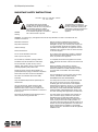
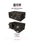
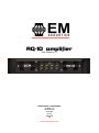
AQ-10 amplifier
User Manual v1.0
EM Acoustics Loudspeakers
Building 74
Dunsfold Park
Cranleigh
Surrey
GU6 8TB
UK
www.emacoustics.co.uk
AQ-10 Operating Instructions
Page 2
AQ-10 Operating Instructions
Page 3
CONTENTS
DECLARATION OF CONFORMITY
4
THANKS
5
INTRODUCTION
5
IMPORTANT SAFETY INSTRUCTIONS
6
INSTRUCTIONS DE SECURITE IMPORTANTES
7
Installing Your Amplifier: Electrical Considerations
8
Installing Your Amplifier: Mechanical Considerations
9
Installing Your Amplifier: RF Emissions
9
About Your Amplifier: Dynamic Amplifier Performance Measurements
10
Connecting To Your Amplifier: Inputs
11
Connecting To Your Amplifier: Speaker Outputs
12
Connecting To Your Amplifier: Bridged (Mono) Operation
13
Operating Your Amplifier: Front Panel Controls and Indicators
14
Operating Your Amplifier: Notes and Switching On
15
Operating Your Amplifier: Rear Panel Sockets and Switches
16
Looking After Your Amplifier: Maintenance
17
Looking After Your Amplifier: Warranty
17
Changing the Gain of Your Amplifier: Internal Adjustments!
18
Performance Of Your Amplifier: Specifications
19
www.emacoustics.co.uk
AQ-10 Operating Instructions
Page 4
DECLARATION OF CONFORMITY
We, the manufacturer:
MC2 Audio,
Units 6-8 Kingsgate
Heathpark Industrial Estate
Honiton, Devon
England
EX14 1YG
acknowledge our responsibility that the following products:
Kind of equipment:
Commodity Code:
Type Designation:
Audio amplifier
8518408990
E100 and all OEM variants of this model
are manufactured:
in accordance with EMC Directive 2004/108/EC,
in compliance with the following norm(s) or document(s):
Technical Regulations: EN55103-1:1996, EN55103-2:1996
and
in accordance with the Low Voltage Directive 2006/95/EC,
in compliance with the following norm(s) or document(s):
Technical Regulations: EN/IEC60065:2002 7 th Edition
Signed:
……………………………………………………………………
Name:
Position:
Date:
Alex Cooper
Research and Development Manager
January 2012
AQ-10 Operating Instructions
Page 5
THANKS
Thank you for choosing an AQ-10 amplifier for your application. Please spend a little time
reading through this manual, so that you obtain the best possible performance from the unit
and become familiar with its operating requirements.
The AQ-10 is designed and manufactured by MC2 Audio in the UK. All MC2 products are
carefully designed and engineered for cutting-edge performance and world-class reliability. If
you would like further information about your AQ-10 or any other EM Acoustics product,
please contact us.
We wish you many years of service from this amplifier and look forward to hearing from you
in the near future.
INTRODUCTION
The AQ-10 is the most powerful four channel amplifier within the EM Acoustics range. It has
been designed to meet demands for higher power and increased efficiency, whilst still
maintaining the renowned sonic qualities and unsurpassed reliability associated with our
loudspeaker products.
MC2 proprietary class-D technology with a dual feedback loop system gives exceptional
transient response and a resonant switch mode power supply with a large reservoir gives
extremely high peak power without any “bass sag”.
Newly designed limiters, linked to the output current monitors and power supply, keep mains
input and output currents within a safe operating area at all times, whilst maintaining
transparent sonic performance.
Running cool in even the most difficult conditions, the AQ-10 can deliver over 2500W into 4
ohms with all channels driven, and a massive 2 x 7400W bridged (4R), with outstanding
distortion and noise figures right up to maximum output.
The amplifier, of course, includes full DC, VHF, thermal and short circuit protection to ensure
continuous trouble-free service.
www.emacoustics.co.uk
AQ-10 Operating Instructions
Page 6
IMPORTANT SAFETY INSTRUCTIONS
CAUTION: RISK OF ELECTRIC SHOCK.
DO NOT OPEN
The lightning flash with arrowhead
The exclamation point within an
symbol within an equilateral triangle is
equilateral triangle is intended to alert
intended to alert the user to the presence
the user of important operating and
of uninsulated “dangerous voltage”
maintenance (servicing) instructions in
within the products enclosure that may
the literature accompanying the
be of sufficient magnitude to constitute a
appliance.
WARNING: Apparatus
CLASS shock
I construction
shall be connected to a MAINS socket outlet with a protective
riskwith
of electric
to persons.
earthing connection.
WARNING: To prevent injury, this apparatus must be securely attached to the rack in accordance with the
installation instructions.
Read these instructions.
Keep these instructions.
Heed all warnings.
Follow all instructions.
Do not use this apparatus near water.
Clean only with a dry cloth.
Do not block any ventilation openings, install in
accordance with the manufacturer’s instructions.
Do not install near any heat sources, such as
radiators, heat registers, stoves or other apparatus
(including amplifiers) that produce heat.
Protect the power cord from being walked on or
pinched particularly at plugs, convenience receptacles
and the pint where they exit from the apparatus.
The mains circuit breaker shall remain readily
accessible.
Only use attachments/accessories specified by the
manufacturer.
Use only with the cart, tripod, bracket or table
specified by the manufacturer, or sold with the
apparatus. When a cart is used, use caution when
moving the cart/apparatus combination to avoid injury
from a tip over.
Disconnect this apparatus during lightning storms or
when unused for a long period of time.
Refer all servicing to qualified service personnel.
Servicing is required when the apparatus has been
damaged in any way, such as if the power-supply cord
or plug is damaged, liquid has been spilled or objects
have fallen into the apparatus, the apparatus has been
exposed to rain or moisture, does not operate normally,
or has been dropped.
Do not expose this equipment to dripping or splashing
and ensure that no objects filled with liquids, such as
vases, are placed on the equipment.
To completely disconnect this equipment from the AC
mains, disconnect the power cord from the mains circuit
breaker.
Where the amplifier is mounted in a rack and
permanently connected to the mains, then the rack
should be installed with a readily accessible connector
or an ALL POLE circuit breaker with 3mm breaking
distances.
This unit is fitted with a 3-wire power cord. For safety
reasons, THE EARTH LEAD SHOULD NOT BE
DISCONNECTED IN ANY CIRCUMSTANCE.
The cooling fans suck cool air in through the front and
blow hot air out at the rear of the unit through the
ventilating grills. The front and rear of the amplifier
should have free exposure to the air (i.e. in a rack leave
the front and rear doors off), with 2cm air gap at the
sides and top. IF AIR IS NOT ALLOWED TO ESCAPE
FROM THE REAR, OVER-HEATING WILL OCCUR. Take
care when mounting other equipment in the same rack.
The mains switch on the amplifiers only switches one
pole of the mains supply, therefore for units with a
detachable cord to be fully disconnected from the
mains, the mains disconnect device (ie mains plug or
mains coupler) should remain readily operable. For
units with a fixed mains lead the external all pole circuit
breaker with 3mm breaking distances is the disconnect
device and therefore the installation of the amplifier
shall be carried out in accordance with all the applicable
installation rules.
AQ-10 Operating Instructions
Page 7
INSTRUCTIONS DE SECURITE IMPORTANTES
ATTENTION: RISQUE DE CHOC ELECTRIQUE.
NE PAS OUVRIR
Le symbole représentant un éclair fléché
dans un triangle équilatéral a pour but
d’alerter l’utilisateur de la présence d’une
“tension dangeruese” non isolée à
l’intérieur du boitier, pouvant être d’une
force suffisante pour constituer un risqué
d’électrocution.
Le point d’exclamation dans un triangle
équilatéral a pour but d’alerter
l’untilisateur de la présence d’instructions
importantes concernant le
fonctionnement et la maintenance, dans
la documentation qui accompagne
l’appariel.
ATTENTION: Appareils de construction de CLASSE I doit être raccordé au réseau électrique via une prise de courant
reliée à la terre.
ATTENTION: Pour éviter toute blessure, cet appareil doit être solidement fixé à la torture, conformément aux
instructions d'installation.
Lisez ces instructions.
l'appareil a été exposé pour pleuvoir ou l'humidité,
n'opère pas normalement, ou a été baissé.
Gardez ces instructions.
N'exposez pas cet équipement au fait de tomber goutte
à goutte ou au fait d'éclabousser et garantissez
qu'aucun objet rempli des liquides, comme les vases,
n'est placé sur l'équipement.
Faites attention à tous les avertissements.
Suivez toutes les instructions.
N'utilisez pas cet appareil près de l'eau.
Faites le ménage seulement avec un tissu sec.
Ne bloquez pas d'ouvertures de ventilation, installez
conformément aux instructions du fabricant.
N'installez près d'aucunes sources de chaleur, comme
les radiateurs, les registres de chaleur, les cuisinières
ou d'autre appareil (en incluant des amplificateurs)
qui produisent la chaleur.
Protégez la corde de pouvoir d'être marché sur ou
pincé particulièrement aux prises de courant, les
réceptacles d'avantage et la pinte où ils sortent de
l'appareil.
Le disjoncteur de conduite principale restera sans
hésiter accessible.
Utilisez seulement des attachements/accessoires
spécifiés par le fabricant.
Utilisez seulement avec le chariot, le trépied, la
parenthèse ou la table spécifiée par le fabricant, ou
vendu avec l'appareil. Quand un chariot est utilisé,
utilisez la prudence en déplaçant la combinaison de
chariot/appareil pour éviter la blessure d'un bout.
Débranchez cet appareil pendant les tempêtes de
foudre ou quand neuf pendant un long terme de
temps.
Renvoyez tout l'entretien au personnel de service
qualifié. L'entretien est exigé quand l'appareil a été
nui de toute façon, comme si la corde de pouvoir
provision ou la prise de courant sont nuis, le liquide a
été déversé ou les objets sont tombés dans l'appareil,
Pour complètement débrancher cet équipement de la
conduite principale de courant alternatif, débranchez la
corde de pouvoir du disjoncteur de conduite principale.
Où l'amplificateur est monté dans un égouttoir et en
permanence raccordé à la conduite principale, alors
l'égouttoir devrait être installé avec un connecteur sans
hésiter accessible ou TOUT le disjoncteur de PÔLE avec
3 millimètres cassant des distances.
Cette unité est correspondue avec une corde de pouvoir
de 3 fils. Pour les raisons de sécurité, l'AVANCE DE
TERRE NE DEVRAIT ÊTRE DÉBRANCHÉE DANS AUCUNE
CIRCONSTANCE.
Les ventilateurs engloutissent l'air frais par le front et
soufflent l'air chaud à l'arrière de l'unité par les grils
aérants. Le front et l'arrière de l'amplificateur devraient
avoir l'exposition libre à l'air (c'est-à-dire dans un
égouttoir omettent les portes de devant et arrière), avec
le trou aérien de 2 centimètres aux côtés et au haut. Si
on NE PERMET PAS QUE D'AIR S'ÉCHAPPE DE
L'ARRIÈRE, LE FAIT DE SURCHAUFFER SE PRODUIRA.
Faites attention en montant d'autre équipement dans le
même égouttoir.
L'interrupteur principal sur les amplificateurs ne coupe
qu'un pôle de l'alimentation secteur. le cordon IEC
permettra de déconnecter l'appareil de l'alimentation
secteur, pour cette raison l'accès à ces fiches (fiche
mâle ou femelle) doit être facilités.
Pour les appareils avec un câble d'alimentation fixe sans
fiche secteur, le dispositif de coupure omnipolaire ayant
une distance d'ouverture de contact d'au moins 3mm,
sera le dispositif permettant la déconnexion complète de
l'appareil.
Pour cette raison l'installation et le raccordement de
l'amplificateur devra ce faire conformément au
réglementation en vigueur.
www.emacoustics.co.uk
AQ-10 Operating Instructions
Page 8
Installing Your Amplifier: Electrical Considerations
The amplifier has been manufactured to comply with your local power supply requirements,
but before connecting the unit to the supply, ensure that the voltage (printed on the rear
panel) is correct.
The amplifier is fitted with either a 100/120V or 220/240V tapped transformer according to
customer requirements.
Make sure power outlets conform to the power requirements listed on the back of the unit.
Damage caused by connecting to improper AC voltage is not covered by the warranty.
SAFETY WARNING
Where a MAINS plug or appliance coupler is used as the disconnect device, it should remain
readily operable.
Where the amplifier is mounted in a rack and permanently connected to the mains, then the
rack should be installed with a readily accessible connector or an ALL POLE circuit breaker
with 3mm breaking distances.
This unit is fitted with a 3-wire power cord.
For safety reasons,
THE EARTH LEAD SHOULD NOT BE DISCONNECTED IN ANY CIRCUMSTANCE.
If ground loops are encountered consult the section on connecting your amplifier on page 11.
The wiring colours are:
230V AREAS:
EARTH = GREEN AND YELLOW
NEUTRAL = BLUE
LIVE = BROWN
120V AREAS:
EARTH = GREEN
NEUTRAL = WHITE
LIVE = BLACK
DO NOT USE THE UNIT IF THE ELECTRICAL POWER CORD IS FRAYED OR BROKEN. The
power supply cords should be routed so that they are not likely to be walked on or pinched
by items placed upon or against them, paying particular attention to cords and plugs and the
point where they exit from the appliance.
ALWAYS OPERATE THE UNIT WITH THE AC GROUND WIRE CONNECTED TO THE
ELECTRICAL SYSTEM GROUND. Precautions should be taken so that the means of grounding
of a piece of equipment is not defeated.
DO NOT REMOVE THE LID. Removing the lid will expose you to potentially dangerous
voltages. There are no user serviceable parts inside.
ESD strikes to the unit’s front panel that are in excess of 4000 volts may cause disturbance to
the status LEDs on the unit. This will not affect audio performance and will be corrected on
the next power up cycle.
AQ-10 Operating Instructions
Page 9
Installing Your Amplifier: Mechanical Considerations
To ensure that this equipment performs to specification, it should be mounted in a suitable
rack or enclosure as described below. Like all high power amplifiers, it should be kept away
from other equipment which is sensitive to magnetic fields. Also, this amplifier may suffer a
substantial reduction in performance if it is subjected to, or mounted close to equipment
which radiates high RF fields.
Warning: To prevent injury, this apparatus must be securely attached to the rack in
accordance with the installation instructions
When mounting the amplifier in a rack or enclosure:
Be aware that…
THE FRONT PANEL IS NOT CAPABLE OF SUPPORTING THE UNIT ON ITS OWN.
Make sure that the rear of the unit is adequately supported. The brackets which are supplied
fit standard 19 inch (483mm) rack mounting systems.
ENSURE THERE IS ADEQUATE VENTILATION.
The cooling fans suck cool air in through the front and blow hot air out at the rear of the unit
through the ventilating grills. The front and rear of the amplifier should have free exposure to
the air (i.e. in a rack leave the front & rear doors off), with 2cm air gap at the sides.
IF AIR IS NOT ALLOWED TO ESCAPE FROM THE REAR, OVER-HEATING WILL OCCUR.
Take care when mounting other equipment in the same rack.
Make sure that the rack unit has a separate earth connection (technical earth).
Please also see the notes regarding maintenance on page 17.
Installing Your Amplifier: RF Emissions
The high frequency resonant converters in the AQ-10 have been designed to have very low
radio frequency (RF) emissions; however even these low level emissions can cause
interference with other equipment.
In order for this to be minimised, the amplifier should be mounted in a metal rack enclosure,
which should have a separate (technical) Earth. Alternatively a separate earth should be
attached to the amplifier at the rear rack mounting bracket.
www.emacoustics.co.uk
AQ-10 Operating Instructions
Page 10
About Your Amplifier: Dynamic Amplifier Performance
Measurements
The AQ-10 is the very latest example of a ‘dynamic amplifier’. This new ‘breed’ of power
amplifiers provide very high peak power levels in a much smaller, and lighter, package than
previously possible with conventional amplifiers.
They are designed specifically for today’s high power audio installations, which use multiple
speakers with electronic crossovers or speaker controllers. These systems can handle very
high transient signals that far exceed their RMS power rating. The AQ-10 amplifier has been
designed to match this requirement and can deliver huge levels of power for short durations.
In order to protect themselves and the loudspeakers that they are driving, continuous signals
such as sine waves, are automatically detected and reduced (ramped down) to a safe level.
When trying to measure the power output however, continuous signals will give totally
incorrect results. A dynamic signal, such as a tone burst, should be used and the levels
measured by monitoring the waveform on an oscilloscope. The power envelope can then be
accurately measured.
Our power output figures are measured using signals with known Crest Factors and are
quoted at the rear of this manual and on our website.
AQ-10 Operating Instructions
Page 11
Connecting To Your Amplifier: Inputs
XLR
M ALE
The inputs are made via 3-pin XLR connectors, which are electronically balanced and should
be connected via a high grade twin core screened cable, as follows:
PIN1: Screen (see note)
PIN2: Hot (signal +)
PIN3: Cold (signal -)
The amplifier is designed to operate with fully balanced equipment and ground loops or loss
of performance may be experienced if connected to unbalanced sources. If it is unavoidable
however, the following wiring should be used. The cable should still be twin core plus screen.
PIN1:
PIN2:
PIN3:
Screen - connected to the chassis of the unbalanced equipment - or left disconnected
at the unbalanced end.
Hot (signal +)
Cold (ground 0V)
NOTE: This amplifier is wired to the latest industry recommendations. PIN1 is connected
directly to the chassis/mains earth. If ground loops (mains hum) are encountered remove the
screen connection from the other end of the cable and leave it open circuit. If problems
persist, consult your dealer/supplier.
DO NOT TAMPER WITH OR ALTER ANY GROUND (EARTH) CONNECTIONS INSIDE THE
AMPLIFIER.
For bridged operation input should be made to channel A (or C) only and the rear panel
switch set for bridged mode for the appropriate pair of channels.
www.emacoustics.co.uk
AQ-10 Operating Instructions
Page 12
Connecting To Your Amplifier: Speaker Outputs
SPEAKON
NL2 & NL4
The speaker outputs are via Neutrik SpeakONTM connectors. 2 pole (NL2FC) or 4 pole (NL4FC)
connectors can be used.
Pin 1+: Hot
Pin 1-: Cold
Additionally the Channel A SpeakONTM connector carries Channel B output on Pins +2 & -2 to
allow easy bi-amping or bridged operation using a single NL4 connector. Similarly, Channel
C’s SpeakONTM connector also carries Channel D output.
Output Connector A
Pin 2+: Hot Ch. B
Pin 2-: Cold Ch. B
Output Connector C
Pin 2+: Hot Ch. D
Pin 2-: Cold Ch. D
For bi-amped operation, connect as above.
There must be no shared connections between channels.
Negative output terminals must not be joined together as they are not both at
ground potential. Connecting them together will damage the amplifier and void
the warranty!
As the currents involved are very high, and to ensure best performance, the speaker cables
should be kept as short as possible and conform to the following minimum requirements:
AQ-10, 20A into 4 Ohm speaker loads
When operating the amplifier into loads of less than 4 Ohms, be aware that the current
capacity of the speaker cables will need to be increased above the values quoted here.
Do not connect the inputs/outputs to any other voltage source such as a battery, mains
source or power supply, regardless of whether the amplifier is turned on or off.
Do not run the output of any amplifier channel back into another channel’s input and do not
parallel or series-connect an amplifier output with any other amplifier output.
AQ-10 Operating Instructions
Page 13
Connecting To Your Amplifier: Bridged (Mono) Operation
Pairs of channels may be independently bridged – channel pair A&B, and/or channel pair
C&D.
The method is the same for both channel pairs:
Supply signal to Channel A or C input only and push in the appropriate rear panel switch
marked “BRG A&B” or “BRG C&D”.
Use Channel A or C’s Output SpeakONTM connector and connect as follows:
Pin 2+: Hot
Pin 1-: Cold
When operating in bridged mode, the minimum impedances are doubled.
The minimum load in bridged mode is 4 ohms.
www.emacoustics.co.uk
AQ-10 Operating Instructions
Page 14
Operating Your Amplifier: Front Panel Controls and Indicators
1: Power Switch: This single pole switch turns the amplifier fully off (but does NOT isolate it
from the mains supply).
2: Power LED: This indicates when the amplifier is active. This does NOT indicate the
presence of a mains supply when the power switch is OFF.
3: Signal Meter and OCM indicators: These LED bar graphs show instantaneous level on
each channel to indicate proximity to the limiter threshold. Note that if the PRC system is in
operation on any channel, this will affect the readout shown on the respective meter.
The red LED in the meter will illuminate when the limiter threshold has been reached and
limiting is occurring. The output current monitor (OCM) may activate to limit the output
current of the amplifier channel - this can occur even if the amplifier has not reached clipping
point.
The OCM indicator can operate independently of the bar graph meter. Typical conditions that
may trigger the OCM circuitry would be very low load impedance, or high subsonic or VHF
levels.
4: Attenuation Controls: These are analogue controls allowing precise level settings. Note
that in bridged (mono) mode some controls may be inactive.
5: Link LED: This indicates if the channel is linked to its immediate neighbour. The link
switches are on the rear panel – see page 16 for details.
6: PRC LED: This illuminates if the Power Reduction Control has been enabled on the
respective channel. PRC switches are on the rear panel – see page 16 for details.
7: Bridge LED: This illuminates when a channel pair have been switched into bridged
(mono) mode (channel A+B or C+D). Note that the partner channel’s LEDs and controls are
disabled when a pair of channels are bridged. Bridge switches are on the rear panel – see
page 16 for details of how to connect your speaker to a bridged channel pair.
8: A/P (Auto Protect) LED: If a condition exists, either internally or externally, that could
cause damage to either the amplifier or the speakers, the protection circuit will disengage the
outputs and the A/P LED will illuminate. The amplifier will continue to be monitored and
depending on the type of fault, will either reset after the fault has cleared or require manual
resetting by switching off at the mains switch and then on again after a few seconds.
AQ-10 Operating Instructions
Page 15
Typical conditions that could cause the protection to be triggered include very high frequency
or subsonic input signals, DC in the inputs, short-circuited outputs, or internal high
temperatures.
The protection circuit can affect all channels or a ‘channel pair’ depending on the type of
fault. This is indicated by the combination of A/P LED and OCM LED illuminating. In this way
it is possible for two channels (a channel pair) to remain functioning even though a fault has
caused the other channel pair to mute. A channel pair would be A+B or C+ D.
Temperature related faults will reset if the unit has cooled sufficiently.
Output short circuits will require manual reset after clearing the fault. Short circuits on either
channel of a channel pair will only affect that channel pair. A/P will illuminate together with
the OCM LED on the shorted channel and the partner channel of the channel pair (so A+B or
C+D).
Operating Your Amplifier: Notes and Switching On
Read all documentation before operating your equipment and retain all documentation for
future reference.
Do not spill water or other liquids into or on the unit and do not operate the unit while
standing in liquid.
Do not block fan intake or rear ventilation outlets or operate the unit in an environment that
could impede the free flow of air around the unit.
If the unit is used in an extremely dusty or smoky environment, it should be cleaned of any
collected debris at regular intervals. Please also see the notes regarding maintenance on page
17.
It is important that the power output of your amplifier is matched to the power handling
capacity of your loudspeaker. If not, damage to the loudspeaker could occur.
Switching On…
At ‘switch-on’ the protection circuit will initially activate whilst the circuits stabilise, indicated
by the red A/P LED illuminating, in addition to various other LEDs. After a few seconds the
red A/P LED will extinguish indicating a satisfactory working
condition.
Other LEDs may remain illuminated depending upon rear panel switch settings and input
connections. If the A/P LED does not extinguish after 5 seconds the unit may be faulty or
some external connections may be incorrect or inappropriate. If this occurs you should power
down the unit and remove all external connections (except for the mains power supply) and
repeat the power up sequence. If the problem persists please contact us – details on page
17.
www.emacoustics.co.uk
AQ-10 Operating Instructions
Page 16
Operating Your Amplifier: Rear Panel Sockets and Switches
3
4
P.R.C.
CH. C
S1 S2
P.R.C.
CH. B
S1 S2
5
LINK A & B
LIN K B & C
B RG
C& D
P.R.C.
CH. D
S1 S2
LINK C& D
2
P.R.C.
CH. A
S1 S2
6
E-SERIES
AM PLIFICATION
1: GND
2: Sig+
3: Sig-
P.R.C.
B RG
A&B
S1
S2
WARNINGS
All vents on front
and rear of unit
must not be
obstructed.
This unit must be
earthed.
Power
Reduction
Control
0dB
CH. D
OUT
CH. C
OUT
CH. B
OUT
CH. A
OUT
SHOCK
HAZARD
-2dB
OUTPUT
-4dB
CONNECTIONS
D C B A
D+
C+
B+
A+
1-
D-
C-
B-
A-
2+
D+
B+
2-
D-
B-
B RG
1+
Do not remove
covers.
-6dB
To reduce the risk
of fire or electric
shock, do not
expose this
apparatus to
rain or moisture.
SERIAL NO.
DESIGNED AND
MANUFACTURED
IN ENGLAND BY
MC
2
1
1: Channel A output SpeakONTM socket: Normal output is on pins 1+ hot, 1- cold. Channel
B’s output is also wired to this socket to enable a single NL4 to provide both channels and to
facilitate easier wiring in bridged mode. Channel B is wired pins 2+ hot, 2- cold.
Similarly channel C’s output SpeakONTM socket carries Channel D’s output. Check the table
on the rear panel for details.
2: Link switch: Press this switch to link the input of the channel to its immediate left.
Multiple channels may be linked using these switches so, for example, to link all outputs to
input A, press all three switches IN and use input A only. The front panel attenuators will still
operate independently when channels are linked.
3: PRC switches: Each channel of the amplifier may be power limited independently using
these pairs of switches in three stages, offering 2, 4 and 6dB of Power Reduction Control.
P.R.C.
S1
S2
Power
Reduction
Control
0dB
-2dB
-4dB
-6dB
The settings for these switches are on the rear panel for quick reference.
4: Input XLR sockets: Connect signal inputs to these sockets, wired pin 2 hot, 3 cold, 1
ground. For sensitivity and impedance of these inputs, please see the specifications on page
18.
5: Bridged (mono) switch (A+B): Press this switch to run this pair of amplifier channels in
bridged mode. To run C+D bridged, press the switch on the far left of the panel, beside
channel D’s input XLR.
6: Fan outlet: The variable speed fans suck air in through the front vents and out through
the back of the amplifier. Please see maintenance on page 17 for recommendations on how
to clean this and the front foam sections.
AQ-10 Operating Instructions
Page 17
Looking After Your Amplifier: Maintenance
These maintenance instructions are for use by qualified personnel only. Before any routine
maintenance, please ensure that your amplifier is disconnected from the mains supply!
The filter behind the air intake apertures on the front of your amplifier should be cleaned or
replaced periodically, e.g. 12-24 months. (Filters in amplifiers located in more 'dirty'
atmospheres may require more frequent maintenance).
The filter should be 'dry' cleaned, using a vacuum cleaner preferably. Running the unit
without a filter is not recommended unless it is within a 'clean room'. Replacement filter
material is available.
If the fan vents on the rear of the amplifier develop a build-up of dust/debris on the finger
guards, they can be cleaned with a dry paintbrush and a vacuum cleaner.
The casework of the amplifier may be cleaned with a lightly dampened cloth – do not use any
solvents as they will damage the paint finish and could remove printing.
If you have any doubts about carrying out maintenance, please refer to a service engineer or
contact your local dealer.
Looking After Your Amplifier: Warranty
Your amplifier is guaranteed for a period of three (3) years from the date of purchase. We
hope that it gives you many more years of reliable service than this, but should anything go
wrong, please contact us to advise you about repairs or any spares you might require.
Please do not attempt to repair the amplifier yourself as doing so will invalidate the warranty.
Our contact details are:
EM Acoustics Loudspeakers
Building 74
Dunsfold Park
Cranleigh
Surrey
GU6 8TB
Tel: +44(0)1483 266520
Fax: +44(0)1483 275619
email: [email protected] for general enquiries
www.emacoustics.co.uk
AQ-10 Operating Instructions
Page 18
Changing the Gain of Your Amplifier: Internal Adjustments!
These instructions are for use by qualified personnel only. Before any routine maintenance,
please ensure that your amplifier is disconnected from the mains supply!
Gain/Sensitivity Settings
Adjustment is by moving a link on the input PCB (PCB741) – one link for each channel.
Channel A’s link is number 1, channel B’s is number 2 and so on.
The gain may be set to 26, 32 (factory default setting) or 36dB.
Remember, setting higher gain does not change the maximum available power but changes
the level of signal input to achieve maximum power. In any case, provided that the input
signal is less than 20dBu/7.7V, the built in limiter circuit will prevent distortion within the
amplifier.
The gain should be set to match the signal level from the source – mixer, equaliser etc.
AQ-10 Operating Instructions
Page 19
Performance Of Your Amplifier: Specifications
Main Specifications
Parameter (Units)
AQ-10
Output Power per channel [Crest Factor = 4.8] (Watts)
8 Ohms
4 Ohms
2 Ohms
1400
2800
3700
8 Ohms
4 Ohms
5300
7400
Output Power per channel bridged [Crest Factor = 4.8] (Watts)
THD+N, 4 Ohms (%)
@1kHz, 1dB below max output power <
@20Hz - 20kHz, 1dB below max output power <
Gain Options (dB)
Sensitivity Options for max power (dBu)
Sensitivity Options for max power (Volts)
Frequency Response, +0/0.5dB (Hz)
Power Consumption, Nominal @ 240V, 4 Ohms (A)
Power Consumption, Nominal @ 120V, 4 Ohms (A)
Dimensions H x W x D (mm)
Amplifier
Boxed
Boxed Shipping – all except UK
0.08
0.15
26 / 32 / 36
16.0 / 10.0 / 6.0
4.9 / 2.5 / 1.5
20 – 20000
7.0
14.0
88 x 482 x 428
230 x 580 x 560
250 x 610 x 600
Weight (kgs)
Amplifier
Boxed – shipping
12.0
14.0
Additional Specifications
Parameter (Units)
AQ-10
Input Impedance – Active Balanced (Ohms)
Input CMRR (dB)
SNR (dB)
Damping Factor, 1kHz, 8 ohms
Signal Limiters Present
Protection Present – Short Circuit / DC Output / Temperature
Mains In-rush Control Present
Output Power per channel, 8 Ohms (Watts)
Sine Wave @ 1kHz
Continuous music [Crest Factor of 2.8 or 9dB]
Continuous music [Crest Factor of 4.8 or 14dB]
Continuous music [Crest Factor of 7.8 or 18dB]
Output Power per channel, 4 Ohms (Watts)
Sine Wave @ 1kHz
Continuous music [Crest Factor of 2.8 or 9dB]
Continuous music [Crest Factor of 4.8 or 14dB]
Continuous music [Crest Factor of 7.8 or 18dB]
Output Power per channel, 2 Ohms (Watts)
Sine Wave @ 1kHz
Continuous music with Crest Factor of 2.8 [9dB]
Continuous music with Crest Factor of 4.8 [14dB]
Continuous music with Crest Factor of 7.8 [18dB]
20k
> 60
105
> 400
Yes
Yes
Yes
1150
1300
1400
1480
2250
2600
2800
2900
3200
3600
3700
3700
Due to continuing product improvement the above specifications are subject to change.
www.emacoustics.co.uk
AQ-10 Operating Instructions
Page 20
Performance Of Your Amplifier: Specifications
Power Consumption and Thermal Emissions – AQ-10
Mains
(V)
240
240
240
120
120
120
Load
(R)
8
4
2
8
4
2
Current Draw
(A)
Thermal Emissions
(W)
No Sig’l
Light
Average
Heavy
No Sig’l
Light
Average
Heavy
2.1
3.0
4.5
8.3
504
528
566
660
2.1
3.9
7.0
14.4
504
551
628
816
2.1
4.5
8.6
19.1
504
564
668
936
4.2
6.0
9.0
16.6
504
528
566
660
4.2
7.8
14.0
28.8
504
551
628
816
4.2
9.0
17.2
38.2
504
564
668
936
No Sig’l = Quiescent, Light = Crest Factor of 7.8(18dB),
Average = Crest Factor of 4.8(14dB), Heavy = Crest Factor of 2.8(9dB)
PRC Settings and Maximum Output
Power Reduction Control Setting
Maximum Power into 8 ohms (W)
-2dB PRC
-4dB PRC
-6dB PRC
Maximum Power into 4 ohms (W)
-2dB PRC
-4dB PRC
-6dB PRC
Maximum Power into 2 ohms (W)
-2dB PRC
-4dB PRC
-6dB PRC
Per Channel
1400
980
560
310
Bridged Pair
5300
3700
2100
1175
2800
1950
1110
620
7400
5160
2940
1640
3700
2580
1470
820
N/A
N/A
N/A
N/A