1
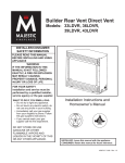
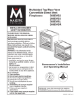
Builder Top Vent Direct Vent Models 33BDVT 36BDVT 39BDVT 43BDVT INSTALLATION INSTRUCTIONS & HOMEOWNER'S MANUAL WARNING! IF THE INFORMATION IN THIS MANUAL IS NOT FOLLOWED EXACTLY, A FIRE OR EXPLOSION MAY RESULT CAUSING PROPERTY DAMAGE, PERSONAL INJURY OR LOSS OF LIFE. FOR YOUR SAFETY WHAT TO DO IF YOU SMELL GAS: Do not try to light any appliance. Do not touch any electric switch Do not use any phone in your building. Immediately call your gas supplier from your neighbours phone. Follow the gas suppliers instructions. * If you cannot reach your gas supplier call the re department * * * * FOR YOUR SAFETY DO NOT STORE OR USE GASOLINE OR OTHER FLAMMABLE VAPOURS AND/OR LIQUIDS IN THE VICINITY OF THIS OR ANY OTHER APPLIANCE. Installation and service must be performed by a qualied installer, service agency or your gas supplier. 410 Admiral Blvd. Mississauga, Ontario, Canada. L5T 2N6 www.majesticproducts.com / www.vermontcastings.com INSTALLER: DO NOT DISCARD THIS MANUAL - LEAVE FOR HOMEOWNER 10002555 05/00 Rev. 0 Vermont Castings, Majestic Products. TABLE OF CONTENTS Thank You & Congratulations On Your Purchase of a Vermont Castings, Majestic Products Fireplace. Please Read The Installation & Operating Instructions Carefully before Using The Appliance. Important: Read all the instructions and warnings carefully before starting the installation. Failure to follow these instructions fully may result in a possible re hazard and will void the manufacturers warranty. Appliance Installation instructions Important curing/burning instructions ........................................................................................3 Locating your replace ...............................................................................................................3 Fireplace Dimensions .................................................................................................................4 Clearance to Combustibles .........................................................................................................5 Mantels........................................................................................................................................5 Hearths ........................................................................................................................................5 Framing and Finishing ................................................................................................................5 Final nishing .............................................................................................................................6 Gas Specications.......................................................................................................................6 Gas Inlet & Manifold Pressures..................................................................................................6 Gas Line Installation ...................................................................................................................7 Remote Switch Installation .........................................................................................................7 Electronic Gas Valve wiring instructions....................................................................................8 EB-1 electrical Box Connection .................................................................................................8 Converting the Appliance Between Gas Types...........................................................................9 Venting Installation Instructions General Venting Information - Terminal Location ...................................................................11 Connecting Direct Vent Components........................................................................................13 How To Use The Vent Graph ....................................................................................................13 Vertical sidewall Applications ..................................................................................................14 Vertical sidewall Installations ...................................................................................................15 Below Grade Installations.........................................................................................................16 Vertical Through-The-Roof Applications .................................................................................17 Vertical Through-The-Roof Installations..................................................................................19 Operating Instructions Glass Warning ...........................................................................................................................20 General Maintenance ................................................................................................................20 Louvre Removal .......................................................................................................................20 Glass/Frame Removal...............................................................................................................20 Glass Cleaning ..........................................................................................................................20 Installation of Logs & Lava Rock.............................................................................................21 Flame & Temperature Adjustment............................................................................................22 Flame Characteristics & Appearance........................................................................................22 Lighting Instructions.................................................................................................................23 Troubleshooting Guide .............................................................................................................25 Replacement Parts Part Number List.......................................................................................................................29 Parts Pictorial ............................................................................................................................31 Optional Accessories Fan Kits.....................................................................................................................................32 Ceramic Refractory Lining .......................................................................................................33 Window Screen Kit...................................................................................................................33 Decorative Bay Window ...........................................................................................................34 Remote Control Units ...............................................................................................................35 33/36/39/43 BDVT -2- 10002555/0 Vermont Castings, Majestic Products. INSTALLATION & OPERATING INSTRUCTIONS This gas replace should be installed by a qualied installer in accordance with local building codes and with current CAN /CGA-B149 (. 1 or .2) Installation codes for Gas Burning Fireplaces and Equipment. FOR U.S.A Installations follow local codes and/or the current National Fuel Gas Code. ANSI Z223.1. FOR SAFE INSTALLATION AND OPERATION PLEASE NOTE THE FOLLOWING: 1. This replace gives off high temperatures and should be located out of high trafc areas and away from furniture and draperies. 2. Children and adults should be alerted to the hazards of the high surface temperatures of this replace and should stay away to avoid burns or ignition of clothing. 3. Caution, due to high glass surface temperature children should be carefully supervised when they are in the same room as the replace. 4. Under no circumstances should this replace be modied. Parts removed for servicing should be replaced prior to operating the replace again. 5. Installation and any repairs to this replace should be carried out by a qualied service person. A professional service person should be contacted to inspect this replace annually. Make it a practice to have all of your gas replaces checked annually. More frequent cleaning may be required due to excess lint and dust from carpeting, bedding material, etc. 6. Control compartments, burners and air passages in this replace should be kept clean and free of dust and lint. Make sure that the gas valve and pilot light are turned off before you attempt to clean this replace. 7. The venting system (chimney) of this replace should be checked at least once a year and if needed your venting system should be cleaned. 8. Keep the area around your replace clear of combustible materials, gasoline and other ammable vapour and liquids. This replace should not be used as a drying rack for clothing, nor should Christmas stockings or decorations be hung on or around the replace. 9. Under no circumstances should any solid fuels (wood, coal, paper or cardboard etc.) be used in this replace. 10. The ow of combustion and ventilation air must not be obstructed in any way. 11. When the replace is installed directly on carpeting, vinyl tile or any combustible material other than wood, the replace must be installed on a metal or wood panel extending the full width and depth of the replace. 12. This replace requires adequate ventilation and combustion air to operate properly. 13. This replace must not be connected to a chimney ue serving a separate solid fuel burning replace. 14. When the replace is not in use it is recommended that the gas control valve be left in the OFF position. 10002555/0 This appliance has been approved for after-market mobile home installations IMPORTANT: PLEASE REVIEW THE FOLLOWING CAREFULLY Remove any plastic from trim parts before turning the replace ON. It is normal for replaces fabricated of steel to give off some expansion and/or contraction noises during the start up or cool down cycle. Similar noises are found with your furnace heat exchanger or car engine. It is not unusual for your Majestic gas replace to give off some odour the rst time it is burned. This is due to the curing of the paint and any undetected oil from the manufacturing process. Please ensure that your room is well ventilated - open all windows. It is recommended that you burn your Majestic replace for a least six (6) hours the rst time you use it. If the optional fan kit has been installed, place the fan switch in the “OFF” position during this time. LOCATING YOUR FIREPLACE X A E B Y X C D X F Fig. 1 A - Flat on the wall C - * Island E - ** Flat on wall (in corner) B - Cross Corner D - ** Room Divider F - Chase Installation * Island (C) and Room Divider (D) installation is possible as long as the horizontal portion of the vent system (X) does not exceed 20' (6.1 m). See details in the venting section of this manual. ** When you install your replace in a Room divider (D) or at on the wall in a corner (E), a minimum distance of 6" (153 mm) clearance must be maintained from the perpendicular wall and the front of the appliance. See (Y) in Fig. 1. -3- 33/36/39/43 BDVT Vermont Castings, Majestic Products. APPLIANCE DIMENSIONS N ROD ROH L M Framing Dimensions ROW E G H F C B I J K A D Appliance Dimensions F Appliance Dimensions Ref. 33BDVT 36BDVT 39BDVT 43BDVT A 838 mm (33") 914 mm (36") 991 mm (39") 1092 mm (43") B 733 mm (28.87") 870 mm (34.25") 870 mm (34.25") 940 mm (37") C 416 mm (16.37") 533 mm (21") 533 mm (21") 570 mm (23.5") D 787 mm (31") 838 mm (33") 914 mm (36") 1016 mm (40") E 559 mm (22") 610 mm (24") 610 mm (24") 787 mm (31") F 356 mm (14") 406 mm (16") 406 mm (16") 406 mm (16") G 810 mm (31.89") 946 mm (37.25") 946 mm (37.25") 1016 mm (40") H 152 mm (6") 181 mm (7.13") 190 mm (7.5") 178 mm (7") I 149 mm (5.87") 171 mm (6.75") 159 mm (6.25") 140 mm (5.5") J 200 mm (7.87") 254 mm (10") 213 mm (8.38") 210 mm (8.25") K 297 mm (11") 343 mm (13.5") 318 mm (12.5") 318 mm (12.5") Framing Dimensions L 894 mm (35.18") 1010 mm (39.75") 1016 mm (40") 1121 mm (44.13") M 1264 mm (49.75") 1403 mm (55.25") 1422 mm (56") 1584 mm (62.38") N 708 mm (24.87") 714 mm (28.13") 718 mm (28.25") 793 mm (31.18") ROD 368 mm (14.5") 419 mm (16.5") 419 mm (16.5") 419 mm (16.5") ROW 851 mm (33.5") 927 mm (36.5") 1003 mm (39.5") 1105 mm (43.5") ROH 737 mm (29") 889 mm (35") 889 mm (35") 959 mm (37.75") 33/36/39/43 BDVT -4- 10002555/0 Vermont Castings, Majestic Products. CLEARANCE TO COMBUSTIBLES Appliance Top............................. 0 mm (0") Bottom....................... 0 mm (0") Side............................ 0 mm (0") Back........................... 0 mm (0") Venting Concentric sections of DV Vent Top, bottom & sides .. 25 mm (1") Ref. V W X Y Z Ref. A B C D E MANTELS The height that a combustible mantel is tted above the replace is dependent on the depth of the mantel. This also applies to the distance between the mantel leg (if tted) and the replace. For the correct mounting height and widths refer to Fig. 2 and the following Mantel Charts. The tting of a bay window trim kit does not effect the distances and reference points referred to in the diagram and chart. Non-combustible mantels and legs may be installed at any height and width around the appliance. When using paint or lacquer to nish the mantel, such paint or lacquer must be heat resistant to prevent discolouration. Mantel Shelf Chart (Minimum Height) Mantel Depth Ref. Mantel Height 10" (254 mm) A 12" (305 mm) 8" (203 mm) B 10" (254 mm) 6" (152 mm) C 8" (203 mm) 4" (101 mm) D 6" (152 mm) 2" (50 mm) E 4" (101 mm) Mantel Leg Dimensions (Minimum Width Mantel Leg Depth Distance From Edge of Glass 10" (254 mm) 10" (254 mm) 8" (203) mm) 8" (203 mm) 6" (152 mm) 6" (152 mm) 4" (101 mm) 4" (101 mm) 2" (51 mm) 2" (51 mm) HEARTH A Hearth is not mandatory but it is recommended for aesthetic purpose. We recommend a non-combustible hearth which projects out 12” (305 mm) or more from the front of the replace. Cold climate Installation Recommendation: When installing this unit against a non-insulated exterior wall or chase, it is mandatory that the outer walls be insulated to conform to applicable insulation codes. V W X FRAMING AND FINISHING Y 1. 2. Z A B C D E 3. 4. Top Louvre Assembly Fireplace 5. Fig. 2 10002555/0 -5- Choose the unit location. Place the unit into position and secure it to the oor with 1.5” (38 mm) screws, or nails. The holes to secure the unit to the oor are located just behind the access door grille on the left and right side of the unit. Frame in the replace with a header across the top. It is important to allow for the nished wall face when setting the depth of the frame. Attach the replace to the frame using the adjustable frame drywall strips (located behind the access door for shipping). Preset the depth to suit the facing material of the wall. The strips are adjustable to 1/2”(13 mm), 5/8” (16 mm) or 3/4” (19 mm), Fig. 3 & 4. Screw through the slotted holes in the drywall strip and into the pre-drilled holes in the replace side. Measure from the face of the replace to the face of the drywall strip to conrm the nal depth. 33/36/39/43 BDVT Vermont Castings, Majestic Products. C B A 33BDVT / 36BDVT / 39BDVT / 43BDVT CERTIFIED TO A = 1/2" (13 mm) Drywall B = 5/8" (16 mm) Drywall C = 3/4" (19 mm) Drywall ANSI Z21.88b-1999 / CSA Z2.33b-M99 Vented Gas Fireplace Heaters GAS SPECIFICATIONS Adjustable Drywall Strip Fig. 3 Model Fuel Gas Control Max. Min. Input Input BTU/h BTU/h 33BDVTRN Nat. Millivolt 15,000 10,500 33BDVTRP Prop. Millivolt 15,000 11,250 Nat. 24V Hi/Lo 15,000 10,500 33BDVTEP Prop. 24V Hi/Lo 15,000 11,250 Nat. Millivolt 18,000 12,600 36BDVTRP Prop. Millivolt 18,000 13,500 Nat. 24V Hi/Lo 18,000 12,600 36BDVTEP Prop. 24V Hi/Lo 18,000 13,500 Nat. Millivolt 22,000 15,400 39BDVTRP Prop. Millivolt 22,000 16,500 33BDVTEN Adjustable 13mm, 16 mm & 19 mm spacing 36BDVTRN 36BDVTEN 39BDVTRN Fig. 4 FINAL FINISHING Non-combustible materials such as brick or tile may be extended over the edges of the face of the appliance. DO NOT cover any vent or grille panels. If a Trim Kit is going to be installed on the replace, the brick or tile will have to be installed ush with the edges of the appliance. 39BDVTEN Nat. 24V Hi/Lo 22,000 15,400 39BDVTEP Prop. 24V Hi/Lo 22,000 16,500 43BDVTRN Nat. Millivolt 25,000 17,500 43BDVTRP Prop. Millivolt 25,000 18,750 43BDVTEN Nat. 24V Hi/Lo 25,000 17,500 43BDVTEP Prop. 24V Hi/Lo 25,000 18,750 GAS INLET & MANIFOLD PRESSURES Natural Gas LP (Propane) Input Minimum 4.5" WC 11" WC Input Maximum 7" WC 13" WC 3.5" WC 10" WC Manifold Pressure 33/36/39/43 BDVT -6- 10002555/0 Vermont Castings, Majestic Products. GAS LINE INSTALLATION REMOTE ON/OFF SWITCH Installation When purging the gas lines, the front glass must be removed. 1. The gas pipeline can be brought in through the rear of the replace as well as the bottom. Knockouts are provided on the bottom behind the valve to allow for the gas pipe installation and testing of any gas connection. It is most convenient to bring the gas line in from the rear right side of the valve as this allows fan installation or removal without disconnecting the gas line. The gas line connection can be made with properly tinned 3/8” copper tubing, 3/8” rigid pipe or an approved ex connector. Since some municipalities have some additional local codes it is always best to consult your local authority and the CAN/CGA-B149 (.1 or .2) installation codes. 2. 3. Thread the wiring through the holes on the end panels of the appliance. Take care not to cut the wire or insulation on metal edges. Route the wire to a conveniently located receptacle box. Attach the wire to the ON/OFF switch and install the switch into the receptacle box. Connect the other ends of the wire to the gas control valve as shown in Fig. 6. Remote ON/OFF switch TP TH 1/2" Gas Supply 1/2" NPT x 1/2" Flare Shut-off Valve TP 3/8" Flex Line (from valve) Gas Control Valve TH Fig. 6 Fig. 5 Alternative Switch Location The remote switch can be installed on the front/side of the access door. Simply mount the switch to the bracket provided and screw the bracket to either side of the frame, lining up the screws with the pre-punched holes, Fig. 7. For U.S.A. Installations consult the current National Fuel Gas Code, ANSI Z223.1 Always check for gas leaks with a mild soap and water solution. Do not use an open ame for leak testing. The gas control is equipped with a captured screw type pressure test point, therefore it is not necessary to provide a 1/8” test point up stream of the control. When using copper or ex connectors use only approved ttings. Always provide a union when using black iron pipe so that the gas line can be easily disconnected for burner or fan servicing. See the gas specication for pressure details and ratings. The replace valve must not be subjected to any test pressures exceeding 1/2 p.s.i.. Isolate or disconnect this and any other gas appliance control from the gas line when pressure testing. Fig. 7 Do not wire the remote ON/OFF wall switch for the gas replace to the 120 volt power supply. 10002555/0 -7- 33/36/39/43 BDVT Vermont Castings, Majestic Products. EB-1 ELECTRICAL BOX ELECTRONIC GAS CONTROL VALVE The replace, when installed, must be electrically connected and grounded in accordance with local codes or, in the absence of local codes, with the current CSA C22.1 Canadian Electric Code. This appliance may be tted with either a Synetek ignition module or a Honeywell ignition module. The method of operation is the same in both cases, however the wiring layout is different therefore it is important to correctly identify the unit and follow the correct wiring diagram. For U.S.A. installations follow the local codes and the national electrical code ANSI/NFPA No 70. Installation the remote electronic starter switch 1. Thread the wiring through the holes on the side panels of the appliance. Take care not to cut the wire or insulation on metal edges. Route the wire to a conveniently located receptacle box. 2. Attach the wire to the ON/OFF switch and install the switch into the receptacle box. 3. Connect the other ends of the wire to the gas control valve as shown in Fig. 9 or 10. It is strongly recommended that the wiring of the EB-1 Electrical Junction Box be carried out be a licensed electrician. Ensure that the power to the supply line has been disconnected before commencing this procedure. The EB-1 Electrical junction box has been tted standard on this model to allow for the easy connection of an optional fan kit. To connect the EB-1 box to the house electrical supply follow the steps below. 1. Unscrew the retaining screw from the EB-1 base plate, Fig. 8 and remove the EB-1 assembly from the appliance. 2. Remove the front cover of the EB-1 box. 3. Remove the plug socket assembly from the EB-1 box. 4. Feed the supply line in through the EB-1 opening in the side of the appliance and then through the back of the EB-1 assembly, Fig 8. 5. Connect the black wire of the power supply line to the brass screw (polarized) of the socket assembly. 6. Connect the white wire of the power line to the chrome screw of the socket assembly. 7. Connect the ground wire of the supply line to the green screw of the socket assembly. 8. Ret the socket assembly back into the electrical box and replace the cover plate. Secure the cable with the clamp on the outside of the EB-1 base plate and ret the EB-1 assembly to the unit with the screw removed in step 1. INSIDE PILOT HONEYWELL IGNITION MODULE MV/VP PV GND RED ORANGE 1 2 3 4 24V GND 24V 5 6 SENSE SPARK 8 9 GREEN BLACK MV ORANGE LO HI POWER CORD NOVA SIT 822 VALVE BLUE WHITE 24 VAC HOT 120 VAC RTN EB-1 assembly GREEN BLACK BLACK BLACK BLACK YELLOW WALL SWITCH 120 VAC HOT 24 VAC RET Retaining screw OFF BLACK WHITE 40VA TRANSFORMER Honeywell Ignition Module Fig. 9 OUTSIDE Fig. 8 33/36/39/43 BDVT -8- 10002555/0 Vermont Castings, Majestic Products. CONVERTING THE APPLIANCE FROM LP TO NATURAL GAS OR NATURAL GAS TO LP. The conversion of this appliance from one gas to another must be carried out by an authorized service provider. PILOT BLACK 1. 2. 3. 4. SYNETEK IGNITION MODULE WHITE 13 12 11 10 9 8 7 6 5 4 3 2 1 PURPLE 5. BLACK RED WHITE LO 6. HI POWER CORD WHITE NOVA SIT 822 VALVE 7. BLUE 24 VAC HOT 120 VAC RTN WHITE BLACK BLACK BLACK OFF WALL SWITCH WHITE GREEN GREEN 120 VAC HOT 24 VAC RET BLACK WHITE 40VA TRANSFORMER Synetek Ignition Module Fig. 10 9. 10002555/0 -9- Disconnect power to the unit and shut off the gas supply. Remove the glass/frame assembly. Carefully remove the logs & lava rock material Remove the screws that are holding the burner housing in place. Remove the burner housing. Depending on the model of the appliance you may have to loosen the pilot bracket retaining screw/nut to allow the pilot and bracket assembly to tilt and give enough clearance to remove the burner housing. Remove the main burner orice and replace it with the orice supplied in the conversion kit. SIT Top Convertible Pilot Gently lift off the pilot hood from the pilot. (Do not remove the spring clip holding the hood in place). Using a correctly sized Allen key unscrew the exposed orice. Insert the new orice supplied in the kit, do not over tighten the orice. Replace the pilot hood ensuring the index tab aligns with the notch on the hood. PSE Pilot Using a suitable wrench on the hexagonal body unscrew the pilot hood assembly from the pilot, do not twist the hood itself. Remove the orice and replace it with the new orice supplied in the kit. Ret the pilot hood assembly. Do not over-tighten the pilot hood. The hood must return to its original alignment. Take care not to damage the thermocouple, thermopile or igniter. SIT 820 NOVA Gas Control Valve (Fig. 11) a) Using a Torx T20 or slotted screwdriver, remove and save the three pressure regulator mounting screws (A), pressure regulator tower (B) and diaphragm (C). b) Ensure the rubber gasket (D) is properly positioned and install the new Hi/Lo pressure regulator to the valve using the new screws (E) supplied with the kit. Tighten screws securely. (Reference torque - 25 in.Lb). c) Install the enclosed identication label (F) to the valve body where it can be easily seen. Honeywell Gas Control Valve (Fig. 12) The Honeywell valve tted to this unit is suitable for use with LP or Natural Gas. It is converted to the required gas application by the installation of a colour coded “conversion screw”. a) Using a suitable small screwdriver lift out the central regulator cap from the ‘Hi - Lo’ knob on the valve. b) Unscrew the exposed conversion screw. c) Insert the new colour coded conversion screw. Do not over-tighten the screw, it must be nger tight. d) Ret the regulator cap. 33/36/39/43 BDVT Vermont Castings, Majestic Products. e) Mount the conversion label supplied with the conversion screw to the valve in a visible position. 10. Reassemble the replace in the reverse order, except for the front glass. Leave this off until the unit has been checked for leaks and the gas supply line has been bled. 11. After bleeding the gas line and checking for leaks with a soap solution, replace the front glass. Fire up the unit, check for ame impingement on the logs, adjusting them if necessary. Check the manifold and supply pressures against the appliance specications. Regulator Cap Conversion Screw Pressure Regulator Housing The procedure for converting from one gas to another is the same regardless of the initial gas used. The only variation is in the orice sizes and component part numbers. Your authorized service provider will ensure the correct parts are used. Honeywell Gas Valve Nova SIT820 Gas Valve 33/36/39/43 BDVT Fig.12 Fig. 11 -10- 10002555/0 Vermont Castings, Majestic Products. GENERAL VENTING INFORMATION — TERMINATION LOCATION Do not locate termination hood where excessive snow or ice build up may occur. Be sure to check vent termination area after snow falls, and clear to prevent accidental blockage of venting system. When using snow blowers, make sure snow is not directed towards vent termination area. Your replace is approved to be vented either through the side wall, or vertically through the roof. – Only venting components specically approved and labelled for this replace may be used. – Minimum clearances between vent pipes and combustible materials is one (1") inch (25 mm). – Venting terminals shall not be recessed into a wall or siding. – Horizontal venting must be installed on a level plane without any incline or decline. There must not be any obstruction such as bushes, garden sheds, fences, decks or utility buildings within 24" from the front of the termination hood. Location of Vent Termination It is imperative that the vent termination be located observing the minimum clearances as shown on this page. *Check with local codes or in absence of same with CAN/ CGA B149 (.1 or .2) Installation Codes (1991) for Canada or for U.S.A. Installations follow the current National Fuel Gas Code, ANSI Z223.1. H N N D V L E C B Fixed Closed F Ope nab le V B B V Openable B V V Fixed Closed J G X B A V TERMINATION CAP X AIR SUPPLY INLET A = clearance above grade, veranda, porch, deck, or balcony [* 12 inches (305mm) minimum] B = clearance to window or door that may be opened [12" (306mm)]. C = clearance to permanently closed window [minimum 12 inches (305mm) recommended to prevent condensation on window] D = vertical clearance to ventilated soft located above the terminal within a horizontal distance of 24 inches (610mm) from the centre-line of the terminal [18 inches (458mm) minimum] E = clearance to unventilated soft [12 inches (305mm) minimum]. F = clearance to outside corner see next page G = clearance to inside corner see next page H = * not to be installed above a meter/regulator assembly within 36 inches (914mm) horizontally from the centreline of the regulator † ‡ * 10002555/0 I G GAS METER G M V K X G A V V RESTRICTED AREA (TERMINATION PROHIBITED) I= clearance to service regulator vent outlet [*72 inches (1828mm) minimum] J = clearance to non-mechanical air supply inlet to building or the combustion air inlet to any other replace [ *12 inches (305mm) minimum] K = clearance to a mechanical air supply inlet [* 72 inches (1828mm) minimum] L = † clearance above paved side-walk or a paved driveway located on public property [*84 inches (2133mm) minimum] M = clearance under veranda, porch, deck [*12 inches (305mm) minimum ‡] N = Clearance above a roof shall extend a minimum of 24" (610mm) above the highest point when it passes through the roof surface, and any other obstruction within a horizontal distance of 18" (450mm). a vent shall not terminate directly above a side-walk or paved driveway which is located between two single family dwellings and serves both dwellings * only permitted if veranda, porch, deck, is fully open on a minimum 2 sides beneath the oor * as specied in CAN/CGA B149 (.1 or .2) Installation Codes (1991) for Canada or for U.S.A. Installations follow the current National Fuel Gas Code, ANSI Z223.1. Note: Local codes or regulations may require different clearances. -11- 33/36/39/43 BDVT Vermont Castings, Majestic Products. Termination Clearances Termination clearances for buildings with combustible and noncombustible exteriors. Inside Corner A V Recessed Location Outside Corner A= Combustible 6"(152mm) Noncombustible 2"(50mm) B= Combustible 6"(152mm) Noncombustible 2"(50mm) V C D C E V B Fig. 13 Fig. 14 Balcony with perpendicular side wall Balcony with no side wall C = Maximum depth of 48" (1219mm) for recessed location. H G V V Combustible & Non-Combustible G= Combustible& Non-Combustible 12"(305mm) J H = 24"(610mm) J = 20"(508mm) Fig. 15 33/36/39/43 BDVT D = Minimum width for back wall of a recessed location. Combustible 38"(965mm) Noncombustible 24"(610mm) Fig. 16 -12- E = Clearance from corner in recessed location. Combustible 6"(152mm) Noncombustible 2"(50mm) Fig. 17 10002555/0 Vermont Castings, Majestic Products. HOW TO USE THE VENT GRAPH GENERAL INFORMATION ON ASSEMBLING DV COMPONENTS The vent chart should be read in conjunction with the following vent installation instructions to determin the relationship of the vertical and horizontal dimensions of the vent system 1. Determine the height of the centre of the horizontal vent pipe exiting through the outer wall. Using this dimension on the Sidewall Vent Graph below, locate the point it intersects with the slanted graph line. 2. From the point of this intersection, draw a vertical line to the bottom of the graph. 3. Select the indicated dimension, and position the replace in accordance with same. EXAMPLE A: If the vertical dimension from the oor of the re place is 11' (3.4 m) the horizontal run to the face of the outer wall must not exceed 14' (4.3 m). EXAMPLE B: If the vertical dimension from the oor of the re place is 7' (214cm), the horizontal run to the face of the outer wall must not exceed 8-1/2' (2.6 m). Crimped End Pipes Before joining elbows and pipes apply a bead of high temperature sealant to the crimped end of the elbow or pipe. Join the pipes using a 2" (50 mm) overlap and secure the joints with three sheet metal screws, Fig. 18. Wipe off excess sealant. CANADIAN INSTALLATIONS: The venting system must be installed in accordance with the current CAN/CGA-B149 (.1 or .2) installation code. U.S.A. INSTALLATIONS: The venting system must conform to local codes and/or the current National Fuel Code ANSI Z223.1. Only venting components manufactured by Vermont Castings, Majestics Products can be used in Direct Vent systems. 1" From crimped end of pipe 1'' 30 Screw Holes BEAD LOCATION 29 Fig. 18 28 27 26 When using Vermont Castings, Majestic Products Twist Lock pipe it is not necessary to use sealant on the joints. The only areas of the venting system that need to be sealed with high temperature silicone sealant are the collars on the replace and termination, and the sliding joint of any telescopic vent section used in the system. To join the twist lock pipes together, simply align the beads of the male end with the grooves of the female end, then while bringing the pipes together, twist the pipe until the ange on the female end contacts the external ange on the male end. It is recommended that you secure the joints with three sheet metal screws however this is not mandatory with twist lock pipe. To make it easier to assemble the joints we suggest putting a lubricant (Vaseline or similar) on the male end of the twist lock pipe prior to assembly. 25 24 23 22 21 20 19 18 17 16 15 14 13 eg: A 12 11 10 9 Vertical Dimension From The Floor Of The Fireplace To The Centre Of the Final Horizontal Vent Pipe Twist Lock Pipes 8 Male End 7 Female End eg: B 6 5 4 3 3 Screw Holes 10002555/0 4 5 6 7 8 9 10 11 12 13 14 15 16 17 18 19 20 Horizontal Dimension From The Outside Face Of The Wall To The Centre Of The Fireplace Vent Flange Fig. 19 -13- 33/36/39/43 BDVT Vermont Castings, Majestic Products. VERTICAL SIDEWALL APPLICATIONS • Since it is very important that the venting system maintain its balance between the combustion air intake and the ue gas exhaust, certain limitations as to vent congurations apply and must be strictly adhered to. The Vent Graph showing the relationship between vertical and horizontal side wall venting will help to determine the various dimensions allowable. If a 90º elbow is used in the horizontal vent run (level height maintained) the maximum horizontal vent length is reduced by 36" (914 mm), (Fig. 22). This does not apply if the 90º elbows are used to increase or redirect a vertical rise (Fig. 23). Example: According to the chart the maximum horizontal vent length in a system with a 7.5' vertical rise is 20' (6 m) and if a 90º elbow is required in the horizontal vent it must be reduced to 17' (5.2 m). In Fig. 22 Dimension A plus B must not be greater than 17' (5.2 m). Minimum clearance between vent pipes and combustible materials is one 1"(25mm) on top, bottom and sides unless otherwise noted. When vent termination exits through foundations less than 20" below siding outcrop, the vent pipe must ush up with the siding. It is always best to locate the replace in such a way that minimizes the number of offsets and horizontal vent length. The horizontal vent run refers to the total length of vent pipe from the ue collar of the replace to the face of the outer wall. Horizontal plane means no vertical rise exists on this portion of the vent assembly. • The maximum number of 90º elbows per side wall installation is three (3). A B 7.5' (2.3 m) A + B = 17' Fig. 22 • 20 ft. (6.1 m) 7.5 ft (2.3 m) • PIPE STRAPS EVERY 3 ft.(914mm) • PIPE STRAPS EVERY 3 ft. (914mm) Fig. 20 • 1 x 90º elbow in horizontal plane = 3' If a 90º elbow is tted directly onto the replace ange the maximum horizontal vent run before the termination or a vertical rise is 36" (914 mm). The maximum number of 45º elbows permitted per side wall installation is two (2). These elbows can be installed in either the vertical or horizontal run. For each 45º elbow installed in the horizontal run, the length of the horizontal run MUST be reduced by 18" (45cm). This does not apply if the 45º elbows are installed on the vertical part of the vent system. The maximum number of elbow degrees in a system is 270º (See Fig. 23). Example: In Figure 23 Elbow 1 = 90º Elbow 2 = 45º Elbow 3 = 45º Elbow 4 = 90º Total angular variation = 270º 4 3 FT (914mm) 1 + 2 + 3 + 4 = 270o 3 1 Fig. 23 Fig. 21 33/36/39/43 BDVT 2 -14- 10002555/0 Vermont Castings, Majestic Products. VERTICAL SIDEWALL INSTALLATIONS STEP 1 Locate vent opening on the wall. It may be necessary to rst position the replace and measure to obtain hole location. Depending on whether the wall is combustible or non-combustible, cut opening to size. (Fig. 24) (For combustible walls rst frame in opening. Fig. 24). X Vent Opening — Combustible Wall (240mm) 9-3/8" 9-3/8" (240mm) Fig. 26 (framing detail) STEP 4 Apply a bead of silicone to the inner and outer ue collars of the replace and using three (3) screws attach an appropriate length of vent to the replace. Follow with the installation of the inner and outer elbow, again secure joints as described in the section 'Joining DV Components'. Vent Opening — Noncombustible Wall 7-1/2" (190mm) Fig. 24 STEP 5 Measure the horizontal length requirement including a 2" (50 mm) overlap, i.e. from the elbow to the outside wall face plus 2" (50 mm)(or the distance required if installing a second 90º elbow. (Fig. 27). COMBUSTIBLE WALLS : Cut a 9-3/8"H x 9-3/8"W (240 mm x 240 mm) hole through the exterior wall and frame as shown (Fig. 24). NON-COMBUSTIBLE WALLS : Hole opening must be 7.5" (190 mm) in diameter. Always install horizontal venting on a level plane. STEP 2 Measure wall thickness and cut zero clearance sleeve parts to proper length (MAXIMUM 12” / 305 mm). Assemble sleeve and attach to restop with #8 sheet metal screws (supplied). Install restop assembly (Fig. 25). X Zero clearance sleeve is only required for combustible walls. #8 SCREWS(2) Maximum Length 12" (294mm) #8 SCREWS(2) #8 SCREWS(2) ADJUSTABLE ZERO CLEARANCE SLEEVE ADJUSTABLE ZERO CLEARANCE SLEEVE FIRESTOP Fig. 25 STEP 3 Place replace into position. (Fig. 26). Measure the vertical height (X) required from the base of the ue collars to the centre of the wall opening. 10002555/0 Fig. 27 -15- 33/36/39/43 BDVT Vermont Castings, Majestic Products. STEP 6 Use appropriate length of pipe sections - telescopic or xed and install the horizontal vent sections. The sections which go through the wall are packaged with the starter kit, and can be cut to suit if necessary. (Fig. 28). Sealing vent pipe and restop gaps with high temperature sealant will restrict cold air being drawn in around replace. Fig. 29 Support horizontal pipes every 3 feet (91 cm) with metal pipe straps. Check replace to make sure it is levelled and properly positioned. BELOW GRADE INSTALLATIONS When it is not possible to meet the required vent terminal clearances of 12" (305mm) above grade level a snorkel vent kit is recommended. It allows installation depth of down to 7 " (178mm) below grade level. The 7" is measured from the centre of the horizontal vent pipe as it penetrates through the wall. Fig. 28 If venting system is installed below ground, we recommend a window well with adequate and proper drainage. STEP 7 Apply high temperature sealant to 4" (100 mm) and 7" (175 mm) collars or the termination one inch away from crimped end. Guide the vent terminations 4" and 7" collars into their respective vent pipes. Double check that the vent pipes overlap the collars by 2" (50 mm). Secure the termination to the wall with screws provided and caulk around the wall plate to weatherproof, Fig. 29. As an alternative to screwing the termination directly to the wall you may also use expanding plugs or an approved exterior construction adhesive. You may also attach the termination with screws through the inner body into the 4" vent pipe however for this method you must extend the 4" pipe approximately 6" (150 mm) beyond the outer face of the wall. 33/36/39/43 BDVT Ensure sidewall venting clearances are observed. If installing a snorkel a minimum 24" vertical rise is necessary. The maximum horizontal run with the 24" vertical pipe is 36" (915mm). This measurement is taken from the collar of the replace (or transition elbow) to the face of the exterior wall. See the Sidewall Vent Graph for extended horizontal run if the vertical rise exceeds 24". 1. Establish vent hole through the wall (Fig. 24). 2. Remove soil to a depth of approximately 16" below base of snorkel. Install drain pipe. Install window well (not supplied). Rell hole with 12" of coarse gravel leaving a clearance of approximately 4" below snorkel. (Fig. 30) 3. Install vent system. 4. Ensure a watertight seal is made around the vent pipe coming through the wall. 5. Apply high temperature sealant caulking (supplied) around the 4" and 7" snorkel collars. 6. Slide the snorkel into the vent pipes and secure to the wall. 7. Level the soil so as to maintain a 4" clearance below snorkel. (Fig. 30) -16- 10002555/0 Vermont Castings, Majestic Products. VERTICAL THROUGH-THE-ROOF APPLICATIONS. DO NOT BACK FILL AROUND SNORKEL. A CLEARANCE OF AT LEAST 4” MUST BE MAINTAINED BETWEEN THE SNORKEL AND THE SOIL ZERO CLEARANCE SLEEVE IF REQUIRED 7DVSKS (SNORKEL) FIRESTOP 7" PIPE This Gas Fireplace has been approved for, • Vertical installations up to 40' (12 m) in height. Up to a 10' horizontal vent run can be installed within the vent system using a maximum of two 90º elbows. (Fig. 32) SCREWS MINIMUM 4" CLEARANCE GROUND WINDOW WELL GRAVEL 24"/608mm MINIMUM* Max. 10 ft (3 m) DRAIN Min. Height 7.5 ft (2.3 m) FOUNDATION WALL * A minimum of 24"/608mm vertical pipe must be installed when using the 7DVSKS/7TDVSKS kit. Max. Height 40 ft (12 m) * The 22" vertical rise (center to center) of the snorkel may be included for calculation of max. horizontal run. Fig. 30 If the foundation is recessed, use recess brackets (not supplied) for securing lower portion of the snorkel. Fasten brackets to wall rst and then secure to snorkel with self-drilling #8 x 1/2 sheet metal screws. It will be necessary to extend the vent pipes out as far as the protruding wall face (Fig. 31). FOUNDATION RECESS Watertight seal around the vent pipe PIPE STRAPS EVERY 3' (920 mm) Fig. 32 SNORKEL • WALL SCREWS SHEET METAL SCREWS • • Fig. 31 10002555/0 -17- Up to two 45º elbows may be used within the horizontal run. For each 45º elbow used on the horizontal level the maximum horizontal length must be reduced by 18". Example: Maximum horizontal length 0 x 45º elbows = 10' 1 x 45º elbow = 8.5' 2 x 45º elbows = 7' A minimum of an 8' vertical rise. Two sets of 45º elbow offsets within these vertical installations. From 0 to a maximum of 8' of vent pipe can be used between elbows. (Fig. 33) 33/36/39/43 BDVT Vermont Castings, Majestic Products. Firebox baffle assembly Max. 8' 4 1 + 2 + 3 + 4 = 270o 3 1 Appliance view from lower front 2 4. Fig. 34 Remove the two (2) screws from the top face of the bafe assembly, Fig. 35. Place the restrictor plate as shown in Fig. 36 and secure by retting the screws. Use these screws to attach the restrictor plate Fig. 35 Fig. 33 • • 7DVCS must be used to support offsets. (Fig. 38)This application will require that you rst determine the roof pitch and use the appropriate starter kit. (See Venting Components List) The minimum height of the vent above the highest point of penetration through the roof is 2'. See Fig. 40. The legs of the restrictor plate must go down Fig. 36 VERTICAL RESTRICTOR PLATE (33BDVT ONLY) When installing the 33BDVT with a Vertical Through-TheRoof congured ue system the restrictor plate, (#10002495) supplied with the appliance MUST BE FITTED TO THE APPLIANCE at installation. 5. 6. Fitting The Restrictor Plate 1. 2. 3. Remove the window glass/frame assembly. Locate the rebox bafe assembly in the top rear area of the rebox, Fig. 34. Remove the four (4) nuts along the front edge, and the three (3) screws along the rear edge of the bafe assembly. Remove the bafe assembly from the rebox. 33/36/39/43 BDVT -18- Ret the bafe assembly to the rebox, replacing the three (3) screws and four (4) nuts. Ret window glass/frame as per the appropriate sections of this manual. 10002555/0 Vermont Castings, Majestic Products. VERTICAL THROUGH-THE-ROOF INSTALLATION 1. 2. 3. 4. 5. 6. 9. Install storm collar and seal around the pipe. 10. Add additional vent lengths for proper height. Fig. 40. 11. Apply high temperature sealant to 4" and 7" collars of vertical vent termination and install. Locate your replace. Plumb to centre of the (4") ue collar from ceiling above and mark position. Cut opening equal to 9-3/8" x 9-3/8" (240 mm x 240 mm). Proceed to plumb for additional openings through the roof. In all cases, the opening must provide a minimum of 1 inch clearance to the vent pipe, i.e., the hole must be at least 9-3/8" x 9-3/8" (240 mm x 240 mm). Place replace into position. Place restop(s) #7DVFS or Attic Insulation Shield #7DVAIS into position and secure. (Fig. 37) SHEETMETAL SCREWS (#5) — 3 PER JOINT SEALANT SHEETMETAL SCREWS (#5) — 3 PER JOINT SEALANT STORM COLLAR STORM COLLAR Attic Insulation Shield Fig. 39 11" 11" JOIST LESS THAN 10' (3m) 2' (610 mm) MIN. 11" Ceiling Installation 2' (610mm) MIN. 10' (3m) UPPER FLOOR 11" JOIST Fig. 40 FIRESTOP SPACER If there is a room above ceiling level, restop spacer must be installed on both the bottom and the top side of the ceiling joists. If an attic is above ceiling level a 7DVAIS (Attic Insulation Shield) must be installed. NAILS (4) Fig. 37 7. 8. Install roof support (Fig. 38) and roof ashing making sure upper ange of ashing is below the shingles. Fig. 39. Install appropriate pipe sections until the venting is above the ashing. (See Fig. 39). Typical roof support application The enlarged ends of the vent section always face downward, Fig. 39. Typical ceiling support application Fig. 38 10002555/0 -19- 33/36/39/43 BDVT Vermont Castings, Majestic Products. GENERAL OPERATING INSTRUCTIONS GLASS INFORMATION GLASS / FRAME REMOVAL 1. 2. Only glass approved by Vermont Castings, Majestic Products should be used on this replace. • • • • 3. 4. 5. The use of any non-approved replacement glass will void all product warranties. Care must be taken to avoid breakage of the glass. Under no circumstances should this appliance be operated without the front glass in place, or with the glass in a damaged condition. Replacement glass (complete with gasket) is available through your Vermont Castings, Majestic Products dealer and should only be installed by a licensed qualied service person. 6. 7. Turn the replace OFF (including the pilot). If the unit has been operating allow time for the components to cool. Remove the top louvre assembly. Open the lower louvre panel. Release the two clamps securing the lower edge of the frame by pulling down on the handles, Fig. 42. Tilt the glass frame out slightly at the bottom, lift the frame up and away rom the replace. To replace the glass frame reverse the procedure. GENERAL MAINTENANCE Burner and Burner Compartment It is important to keep the burner and the burner compartment clean. At least once per year the logs and lava rock/ember material should be removed and the burner compartment vacuumed and wiped out. Remove and ret the logs as per the instructions in this manual. Lower clamps Always handle the logs with care as they are fragile and may also be hot if the replace has been in use. FK24/FK12 Fan Assembly The fan unit requires periodic cleaning. At least once per month in the operating season open the lower louvre panels and wipe or vacuum the area around the fan to remove any build up of dust or lint. WINDOW FRAME WINDOW FRAME Brass Trim Clean the brass trim pieces using a soft cloth lightly dampened with lemon oil. Do not use water or household cleaners on any brass components. Fig. 42 GLASS CLEANING LOUVRE REMOVAL It is necessary to periodically clean the glass. During start-up condensation, which is normal, forms on the inside of the glass. This condensation causes lint, dust and other airborne particles to cling to the glass surface. Also initial paint curing may deposit a slight lm on the glass. It is therefore recommended that the glass be cleaned two or three times with a non-ammonia based household cleaner and warm water (we recommend gas replace glass cleaner) within the rst few weeks of operation. After this initial cleaning process the glass should be cleaned two or three times during each operating season depending on the environment in the house. The top louvre panel is removed by lifting the panel vertically and pulling it away from the appliance, Fig. 41. The lower access door is hinged along the bottom edge and is folded down to allow access. 2. 1. LOUVRE GLASS PANEL 33/36/39/43 BDVT PULL CLAMP HOOK PUSH CLAMP HANDLE Clean the glass after the rst two weeks of operation. Fig. 41 -20- 10002555/0 Vermont Castings, Majestic Products. INSTALLATION OF LOGS & LAVA ROCK BA5 BA4 BA6 Refer to the log identication chart to identify specic log numbers. 1. Remove the front glass / frame assembly. 2. Remove the logs from their packaging. The logs are fragile and should be handled with care. Keep the packaging material out of the reach of children and dispose of the material in a safe manner 3. 4 5. 6. 7. 8. 9. 33BDVT BA2 Place the rear log (see chart for identication number) in the rear support channel. The at face should be at against the rear of the rebox and the log should be central in the channel. Align the holes in the base of the left front log with the studs on the left support bracket located over the burner housing and place the log in position. Align the holes in the base of the right front log with the studs on the right support bracket located over the burner housing and place the log in position. Place the left top log in position by aligning the hole on the underside of the log with the lug on the top face of the rear log. The front end of the log rests in the cut-out on the left front log. Place the right top log in position by aligning the hole on the underside of the log with the lug on the top face of the rear log. The front end of the log rests in the cut-out on the right front log. Scatter the ember material over the burner housing in font of the 2 front logs. Do not pack this material tightly, separate it when unpacked and keep it in a loose condition. Scatter the lava rock material around the rebox base. BB10 BB8 BB6 BC7 BA3 Fig. 43 BB9 BB7 Fig. 44 36BDVT BC8 BC9 Do not place any of the lava rock material on the burner housing. BC5 Log Identication Chart Location Front left BA2 BB6 BC5 BD6 Front right BA3 BB7 BC6 BD7 Rear BA4 BB8 BC7 BD8 Top left BA5 BB9 BC8 BD9 Top right BA6 BB10 BC9 BD10 BD6 10002555/0 BD10 BD9 33BDVT 36BDVT 39BDVT 43BDVT -21- BC6 Fig. 45 39BDVT BD8 43BDVT BD7 Fig. 46 33/36/39/43 BDVT Vermont Castings, Majestic Products. FLAME & TEMPERATURE ADJUSTMENT RN/RP & EN/EP Models For units equipped with ‘HI/LO’ valves the ame adjustment is accomplished by rotating the ‘HI/LO’ adjustment knob located near the centre of the gas control valve, Fig. 47 & 48 Turn counterclockwise to decrease flame height Turn clockwise to increase flame height Honeywell Valve 33BDVT Fig. 50 Fig. 47 Turn counterclockwise to increase flame height Turn clockwise to decrease flame height SIT 820 Valve Fig. 48 36BDVT Fig. 51 FLAME CHARACTERISTICS It is important to periodically perform a visual check of the pilot and burner ames. Compare them to the pictorials illustrated below, Figs. 49 - 53. If the ame patterns appear abnormal contact a qualied service provider for service and adjustment. SIT Top Convertible 39BDVT Fig. 52 SIT SIT EN/EP 43BDVT Fig. 49 33/36/39/43 BDVT -22- Fig. 53 10002555/0 Vermont Castings, Majestic Products. LIGHTING AND OPERATING INSTRUCTIONS FOR YOUR SAFETY READ BEFORE LIGHTING WARNING: If you do not follow these instructions exactly, a re or explosion may result causing property damage, personal injury or loss of life. A. This replace has a pilot which must be lit manually. When lighting the pilot follow these instructions exactly. B. BEFORE LIGHTING smell all around the replace area for gas. Be sure to smell next to the oor because some gas is heavier than air and will settle on the oor. WHAT TO DO IF YOU SMELL GAS •Do not try to light any replace. •Do not touch any electric switch •Do not use any phone in your building •Immediately call your gas supplier from a neighbour's phone. Follow the gas supplier's instructions. •If you cannot reach your gas supplier, call the Fire Department C. Use only your hand to push in or turn the gas control knob. Never use tools. If the knob will not push in or turn by hand, do not try to repair it, call a qualied service technician. Applying force or any attempted repair may result in a re or explosion. D. Do not use this replace if any part has been under water. Immediately call a qualied service technician to inspect the replace and to replace any part of the control system and any gas control which has been under water. LIGHTING INSTRUCTIONS 2. 3. 4. 5. 7. 8. 9. OFF P IL O T 3/8" - 1/2" OFF EURO SIT ON OFF PILOT 6. 10. Push the control knob all the way in and hold. Immediately light the pilot by repeatedly depressing the piezo spark ignitor until a ame appears. Continue to hold the control knob in for about one (1) minute after the pilot is lit. Release knob and it will pop back up. Pilot should remain lit. If it goes out, repeat steps 5 through 8. STOP! Read the safety information above on this page. Turn off all electrical power to the replace. For MN/MP/TN/TP appliances ONLY, go on to Step 4. For RN/RP appliances turn the On/Off switch to “OFF” position or set thermostat to lowest level. Open control access panel. Push in gas control knob slightly and turn clockwise to "OFF". Do not force. ON 1. SIT NOVA HONEYWELL Wait ve (5) minutes to clear out any gas. Then smell for gas, including near the oor. If you smell gas, STOP! Follow "B" in the safety information above on this page. If you don't smell gas, go to the next step. Remove glass door before lighting pilot. (See Glass Frame Removal in manual). Visibly locate pilot by the main burner. Turn knob on gas control counter clockwise to "PILOT". 11. 12. 13. 14. • If knob does not pop up when released, stop and immediately call your service technician or gas supplier. • If after several tries, the pilot will not stay lit, turn the gas control knob to "OFF" and call your service technician or gas supplier. Replace glass door. Turn gas control knob to "ON" position. For RN/RP appliances turn the On/Off switch to "ON" position or set thermostat to desired setting. Turn on all electrical power to the replace. TO TURN OFF GAS TO FIREPLACE 1. 2. Turn the On/Off switch to “OFF” position or set the thermostat to lowest setting. Turn off all electric power to the replace if service is to be performed. 10002555/0 3. 4. 5. -23- Open control access panel. Push in gas control knob slightly and turn clockwise to "OFF". Do not force. Close control access panel. 33/36/39/43 BDVT Vermont Castings, Majestic Products. LIGHTING AND OPERATING INSTRUCTIONS For Fireplaces Equipped With SIT822 Gas Valve (EN or EP) WARNING: If you do not follow these instructions exactly, a re or explosion may result causing property damage, personal injury and loss of life. FOR YOUR SAFETY READ THE FOLLOWING WARNINGS BEFORE LIGHTING THE APPLIANCE A. This replace is equipped with an ignition device which automatically lights the pilot.. DO NOT try to light the pilot by hand. B. BEFORE OPERATING, smell all around the appliance area for gas. Be sure to smell next to the oor because some gas is heavier than the air and will settle on the oor. What to do if you smell gas • Do not try to light any appliance. • Do not operate any electrical switch. • Do not use any phone in your building. • Immediately call your gas supplier from a neighbours phone. Follow the gas suppliers instructions. • If you cannot contact your gas supplier call the Fire Department. C. Use only your hand to push in or turn the gas control knob. Never use tools. If the knob will not push in or turn by hand do not try to repair it, call a qualied service technician. Force or attempting repair may result in a re or explosion. D. Do not use this appliance if any part has been under water. Immediately call a qualied service technician to inspect the appliance and to replace any part of the control system and any gas control which has been under water. 1. 6. LIGHTING INSTRUCTIONS 2. 3. 4. 5. STOP! Read the safety information above before continuing. Turn off all electrical power to the appliance. This appliance is equipped with an ignition device which automatically lights the pilot. DO NOT try to light the pilot by hand. Access the gas control by lowing the lower access door (louvre assembly). Turn the remote switch,if used, OFF. Turn the wireless remote, if used, OFF. Wait ve (5) minutes to clear out any gas. Then smell for gas, including near the oor. If you smell gas STOP. Follow instructions B in the safety warnings above. If you do not smell gas go onto the next step. 7. Close the access door. 8. Turn ON all electrical power to the appliance. 9. Turn remote switch or wireless remote to ON 10. If the appliance will not operate, follow the instructions TURNING OFF THE GAS TO THE APPLIANCE and call your service technician or gas supplier. LO HI TURNING OFF THE GAS TO THE APPLIANCE 1. 2. 3. 4. Turn the remote switch to the OFF position. Turn OFF all electrical power to the replace if service is required. Open the lower access panel. Turn the shut-off valve on the exible gas line to the OFF position. 33/36/39/43 BDVT Gas Supply Shut of valve Flex Line Valve in the OFF position -24- 10002555/0 Vermont Castings, Majestic Products. TROUBLE SHOOTING THE GAS CONTROL SYSTEM HONEYWELL MILLIVOLT VALVE START CHECK • GAS SUPPLY ON NO YES PILOT LIGHTS WITH PIEZO IGNITOR NO YES PILOT STAYS LIT YES • LOCKOUT HAS ENGAGED. WAIT 60 SECONDS AND TRY AGAIN. • FOR SPARK AT ELECTRODE WHILE DEPRESSING PIEZO — 1/8" GAP TO PILOT HOOD NEEDED. • ALL WIRING CONNECTIONS • REPLACE PIEZO IGNITOR NO • FOR AIR IN THE LINES • THERMOPILE NEEDS A MINIMUM 325mV. ADJUST PILOT FLAME HEIGHT. • ALL WIRING CONNECTIONS. • REPLACE THERMOPILE • THERMOCOUPLE NEEDS A MINIMUM OF 14mV. • DEFECTIVE VALVE. TURN TO PILOT, METER SHOULD READ GREATER THAN 100 mV. IF NOT, REPLACE. NO • VALVE IS TURNED ON • ON/OFF SWITCH IS NOT TURNED ON. WATCH FOR GROUNDED WIRES! • THERMOPILE NEEDS A MINIMUM 325mV. • PLUGGED BURNER ORIFICE. YES PILOT LIGHTS MAIN BURNER • SUPPLY LINE HOOKED UP • SHUTOFF VALVE OPEN SYSTEM OK. FP396 NVC-standing pilot troubleshooting 11/22/96 10002555/0 -25- 33/36/39/43 BDVT Vermont Castings, Majestic Products. TROUBLE SHOOTING THE GAS CONTROL SYSTEM SIT NOVA 820 MILLIVOLT VALVE Note: Before trouble shooting the gas control system, be sure external gas shut off is in the "On" position. WARNING: BEFORE DOING ANY GAS CONTROL SERVICE WORK, REMOVE GLASS FRONT. SYMPTOM 1. Spark ignitor will not light POSSIBLE CAUSES A. Defective or misaligned electrode at pilot. Using a match, light pilot. If pilot lights, turn off pilot and push the red button again. If pilot will not light - check gap at electrode and pilot-should be 1/8" to have a strong spark. B. Defective ignitor (Push Button) Push Piezo Ignitor Button. Check for spark at electrode and pilot. If no spark to pilot, and electrode wire is properly connected, replace ignitor. 2. Pilot will not stay lit after A. Defective pilot generator carefully following lighting (thermocouple), remote wall instructions. switch. 3. Pilot burning, no gas to main burner CORRECTIVE ACTION 1. Check pilot ame. Must impinge on thermocouple/ thermopile. Note: this pilot burner assembly utilizes botha thermocouple and a thermopile. The thermocouple operates the main valve operation (On and Off). Clean and or adjust pilot for maximum ame impingement on thermopile and thermocouple. B. Defective automatic valve Turn valve knob to "Pilot". Maintain ow to pilot; mil liv olt meter should read greater than 10 mV. If the reading is okay and the pilot does not stay on, replace the gas valve. Note: An interrupter block (not supplied) must be used to conduct this test. A. Wall switch or wires defective Check wall switch and wires for proper connections. Jumper wire across terminals at wall switch, if burner comes on, replace defective wall switch. If okay, jumper wires across wall switch wires at valve, if burner comes on, wires are faulty or connections are bad. B. Thermopile may not be generating sufcient millivoltage. 1. Be sure wire connections from thermopile at gas valve terminals are tight and thermopile is fully inserted into pilot bracket. 2. One of the wall switch wires may be grounded. Remove wall switch wires from valve terminals if pilot now stays lit, trace wall switch wiring for ground. May be grounded to replace or gas supply. 3. Check thermopile with millivolt meter. Take reading at thermopile terminals of gas valve. Should read 250-300 millivolts (minimum 150) while holding valve knob depressed in pilot position and wall switch "Off". Replace faulty thermopile if reading is below specied minimum C. Plugged burner orice. 4. Frequent pilot outage problem. 33/36/39/43 BDVT Check burner orices for debris and remove. D. Defective automatic valve operator. Turn valve knob to "On", place wall switch to "On" millivolt meter should read greater than 100 mV. If the reading is okay and the burner does not come on, replace the gas valve. A. Pilot ame may be too low or blowing (high) causing the pilot safety to drop out. Clean and/or adjust pilot ame for maximum ame impingement on thermopile and thermocouple. B. Possible blockage of the vent terminal. Check the vent terminal for blockage (recycling the ue gases) -26- 10002555/0 Vermont Castings, Majestic Products. TROUBLE SHOOTING THE GAS CONTROL SYSTEM SIT 822 Valve with a Synetek Electronic Ignitor Remove glass before servicing. Operating Diagram NORMAL OPERATION ABNORMAL OPERATION ON/OFF SWITCH CLOSED? LED ON 5 Sec. Inter-Trial Delay YES SAFE START CHECK ON? LOCKOUT: LED, STEADY FLASH. Reset by interrupting On/Off switch or Power for 10 seconds. NO YES 0 Sec. PURGE IGNITION TRIAL: 30 Sec SPARK ON. PILOT VALVE ON. HAS FLAME BEEN DETECTED WITHIN 30 Sec? LOCKOUT: LED 2 FLASHES. Reset by interrupting On/Off switch or Power for 10 seconds. NO YES YES PILOT VALVE OFF. SPARK OFF. HAVE THREE IGNITION TRIALS BEEN COMPLETED? SPARK OFF. MAIN VALVE ON. PILOT FLAME CONTINUOUSLY MONITORED. PILOT FLAME SENSE OK? LOCKOUT: LED 3 FLASHES. Reset by interrupting On/Off switch or Power for 10 seconds. NO YES ON/OFF SWITCH OPENED? YES PILOT AND MAIN VALVE OFF? NO NO YES MAIN VALVE OFF. SPARK ON. HAS FLAME BEEN DETECTED WITHIN 30 Sec. NO 0 Sec. POSTPURGE? HAVE THREE PILOT FLAME LOSSES BEEN DETECTED? YES HEATING CYCLE COMPLETE. LED OFF ON 2 Flashes 3 Flashes Constant Flash 10002555/0 LED CODES = Normal Operation = Pilot ignition Failure (3 trials max.) = Pilot Flame Lost 3 Times = Flame Detached Out of Sequence -27- 33/36/39/43 BDVT Vermont Castings, Majestic Products. TROUBLE SHOOTING THE GAS CONTROL SYSTEM SIT 822 Valve with a Honeywell Electronic Ignitor Remove glass before servicing. START •TURN GAS SUPPLY OFF • TURN ON/OFF SWITCH TO "ON" CHECK: NO POWER TO MODULE (24V NORMAL) YES SPARK ACROSS IGNITOR SENSOR GAP NO • LINE VOLTAGE (120VAC) • LOW VOLTAGE TRANSFORMER (19.5 minimum VAC) • ON/OFF SWITCH • WIRING CONNECTIONS UNPLUG IGNITION LEAD AND CHECK SPARK AT MODULE (24VAC normal) NO • REPLACE MODULE SPARK OK? YES YES • CHECK IGNITION CABLE GROUND WIRING, CERAMIC INSULATOR AND GAP. CORRECT AS NECESSARY • CHECK BOOT OF IGNITION CABLE FOR SIGNS OF MELTING OR BUCKLING. TAKE PROTECTIVE ACTION TO SHIELD CABLE AND BOOT FROM EXCESSIVE TEMPERATURES. • TURN GAS ON NO • CHECK THAT ALL MANUAL GAS VALVES ARE OPEN, SUPPLY TUBING AND PRESSURES ARE GOOD, AND PILOT BURNER ORIFICE IS NOT BLOCKED. • CHECK ELECTRICAL CONNECTIONS BETWEEN MODULE AND PILOT OPERATOR ON GAS CONTROL. • CHECK FOR 24VAC ACROSS PV-MVPV TERMINALS ON MODULE IF VOLTAGE IS OKAY, REPLACE GAS CONTROL IF NOT, REPLACE MODULE. PILOT BURNER LIGHTS? YES SPARK STOPS WHEN PILOT IS LIT? NO YES MAIN BURNER LIGHTS? NO YES SYSTEM RUNS UNTIL ON/OFF SWITCH IS IN "OFF" POSITION YES TROUBLESHOOTING ENDS 33/36/39/43 BDVT NOTE: IF S8600B GOES INTO LOCKOUT, RESET SYSTEM. • CHECK CONTINUITY OF IGNITION CABLE AND GROUND WIRE. • CLEAN FLAME ROD • CHECK ELECTRICAL CONNECTIONS BETWEEN FLAME ROD & MODULE. • CHECK FOR CRACKED CERAMIC FLAME ROD INSULATOR. • CHECK THAT PILOT FLAME COVERS FLAME ROD AND IS STEADY BLUE • ADJUST PILOT FLAME. • IF PROBLEM PERSISTS, REPLACE MODULE. NO • CHECK FOR 24VAC ACROSS MV-MVPV TERMINALS IF NO VOLTAGE, REPLACE MODULE. • CHECK ELECTRICAL CONNECTIONS BETWEEN MODULE AND GAS CONTROL. IF OKAY, REPLACE GAS CONTROL, OR GAS CONTROL OPERATOR. NOTE: IF S8600B GOES INTO LOCKOUT, RESET SYSTEM • CHECK FOR CONTINUITY OF IGNITION CABLE AND GROUND WIRE. NOTE: IF GROUND IS POOR OR ERRATIC, SHUTDOWN MAY OCCUR OCCASIONALLY EVEN THOUGH OPERATION IS NORMAL AT THE TIME OF CHECKOUT. • CHECK THAT THE PILOT FLAME COVERS FLAME ROD AND IS STEADY AND BLUE. • IF CHECKS ARE OKAY, REPLACE MODULE. -28- 10002555/0 Vermont Castings, Majestic Products. REPLACEMENT PARTS LIST Items marked ‘*’ are not shown in the following parts pictorial page. Ref. Description 33BDVT 36BDVT 39BDVT 43BDVT 10000470 1000023 10000024 10000025 1 Log Set (complete) 1a Log - Front left BA2 BB6 BC5 BD6 1b Log - Front right BA3 BB7 BC6 BD7 1c Log - rear BA4 BB8 BC7 BD8 1d Log - Top left BA5 BB9 BC8 BD9 1e Log - Top right BA6 BB10 BC9 BD10 * Lava rock package 10001454 10001454 10001454 10001454 * Ember material 51915 51915 51915 51915 2a Burner housing with tiles, Nat. 10002407 10000031 10000033 10000035 2b Burner housing with tiles, Prop. 10002407 10000032 10000034 10000036 * Ceramic tile, single 57803 57803 57803 57803 * Orice, burner, Nat and Prop. 3a Pilot assembly, SIT RN - 10000674 10000674 10000674 3b Pilot assembly, SIT RP - 10000675 10000675 10000675 4a Pilot assembly, SIT EN - 10000670 10000670 10000670 4b Pilot assembly, SIT EP - 10000671 10000671 10000671 5a Pilot assembly, SIT Top Convertible RN 10002264 - - - 5b Pilot assembly, SIT Top convertible RP 10002265 - - - 6a Pilot assembly, SIT Top convertible EN 10002387 - - - 6b Pilot assembly, SIT Top convertible EP 10002266 - - - 7 Pilot, SIT - 10001295 10001295 10001295 8 Pilot,, SIT Top convertible 10002266 - - - * Pilot orice, SIT Nat. - 54273 54273 54273 * Pilot orice, SIT Prop. - 54272 54272 54272 * Pilot orice, SIT Top convertible Nat. 10002268 - - - * Pilot orice, SIT Top convertible Prop. 10002269 - - - 9 Pilot hood, SIT Top convertible 10002385 - - - 10 Thermocouple, RN & RP 53373 53373 53373 53373 11 Thermopile, RN & RP 51827 51827 51827 51827 12 Pilot tube (with ttings 10001296 10001296 10001296 10001296 * Manifold tube (with ttings) 57318 57318 57318 57318 * Flexible gas line withe ON/OFF valve 20002500 - - - 13 Electrode igniter SIT (with cable), RN & RP 10001297 10001297 10001297 10001297 * Cable igniter, EN & EP 10000696 10000696 10000696 10000696 14 Piezo igniter, SIT 820 Valve 52464 52464 52464 52464 15 Piezo igniter, Honeywell Valve 20000062 - - - 16a Gas Valve SIT820 RN 52677 52677 52677 52677 16b Gas Valve SIT820 RP 52678 52678 52678 52678 17a Gas Valve Honeywell RN 10001782 - - - 10002555/0 See the rating plate for orice specications -29- 33/36/39/43 BDVT Vermont Castings, Majestic Products. 17b Gas Valve, Honeywell RP 10001759 - - - 18a Gas Valve, SIT822 EN 57884 57884 57884 57884 18b Gas Valve, SIT822 EP 57883 57883 57883 57883 * Sensing electrode (with cable) EN & EP 57885 57885 57885 57885 19 Transformer, EN & EP 7522409 7522409 7522409 7522409 * Ignition Module, Synetek, EN & EP 57899 57899 57899 57899 20 Ignition Module, Honeywell, EN & EP 20000005 20000005 20000005 20000005 * Wire harness, Synetek, EN & EP 10000417 10000417 10000417 10000417 * Wire harness, Honeywell, EN & EP 10001979 10001979 10001979 10001979 21 Fan assembly (with bracket) (FK24 option) 54103 54103 54103 54103 * Electrical cord, (FK24 option). 51865 51865 51865 51865 * Fan temperature sensor, (FK24 option) 51704 51704 51704 51704 * Fan speed control, (FK24 option) 51738 51738 51738 51738 * Knob, fan speed control, (FK24 option) 51882 51882 51882 51882 22 Fan assembly, with bracket (FK12 option) ZA1110 ZA1110 ZA1110 ZA1110 23 Window frame assembly 10001803 10001425 54363 54570 * Window glass (with gasket) 10000481 55686 57437 57438 * Gasket (window glass) 57317 57317 57317 57317 24 Clamp, window frame assembly 54174 54174 54174 54174 25 Window trim, polished brass (with magnets) 55005 57480 57483 57485 26 Top louvre assembly 10000292 10000037 10000039 10000041 27 Bottom Louvre assembly 10000293 10000038 10000040 10000042 28 Hinge (bottom louvre assembly 52356 52356 52356 52356 * Restrictor plate 10002495 - - - * Remote ON/OFF switch 51842 51842 51842 51842 * Remote switch kit (switch, wire & bracket) 53875 53875 53875 53875 33/36/39/43 BDVT -30- 10002555/0 Vermont Castings, Majestic Products. PARTS PICTORIAL 3a/b 5a/b 4a/b 26 25 23 6a/b 13 13 9 11 10 11 10 7 8 27 12 24 28 12 9 19 10 10 1e 1d 7 8 13 13 1 1c 16a/b 20 33BDVT 1a 1b 14 21 18a/b 1e 1d 1 LO HI 22 PILOT ADJ 1 1b 1 15 1e 1d 10002555/0 39BDVT 1b 17a/b 1e 1d 1c 1a OFF ON P IL O O H 36BDVT 1a L I T 1c 1c 1a 43BDVT -31- 1b 2a/b 33/36/39/43 BDVT Vermont Castings, Majestic Products. OPTIONAL ACCESSORIES AVAILABLE FK12 FAN KITS This auxiliary fan system increases the efciency of the circulation of the heating air. The FK12 Fan Assembly is a xed speed fan system and does not allow for variable speed control. It does not use the speed control unit or the heat sensor used in the FK24 Kit. Specications 115 Volts / 60 Hz / 56 Watts. FK24 Fan Assembly This auxiliary fan system increases the efciency of the circulation of the heating air. The FK24 fan kit allows variable speed control of the circulation fan and also incorporates a heat sensor in the circuit. Specications 115 Volt / 60 Hz / 56 Watts Maintenance The fan itself does not require regular maintenance, however periodic cleaning of the fan and the surrounding area is required. Check the area under the control door (lower louvre assembly) and in front of the fan and wipe or vacuum this area at least once a month during the operating season. Maintenance The fan itself does not require regular maintenance, however periodic cleaning of the fan and the surrounding area is required. Check the area under the control door (lower louvre assembly) and in front of the fan and wipe or vacuum this area at least once a month during the operating season. Installation The fan assembly is supplied fully wired eliminating the need for a licensed electrician to carry out the installation 1. Open the lower Louvre assembly. Maneuver the fan & bracket assembly around the gas valve and lines to locate the unit against the back wall of the appliance, resting on the base. 2. With the protective cover removed from the self-adhesive ‘Velcro’ strips apply mild pressure to the fan & bracket unit to secure the strips to the metal panels. No further securing is required. 3. Power to the fan can be supplied by plugging the supplied lead into a conveniently located wall socket or by using a hard-wired EB1 connector box. Installation The fan assembly and other components are supplied fully wired eliminating the need for a licensed electrician to carry out the installation If hard wiring the fan in using Method B (following) we strongly recommend the use of a licensed electrician. 1 Open the lower Louvre assembly. Maneuver the fan & bracket assembly around the gas valve and lines to locate the unit onto the screw studs on the back of the replace 2 Install the thermal sensor under the bottom of the rebox, locating it over the two 10 mm studs and secure it with nuts. 3 Locate the fan speed control unit. This can be tted behind the lower louvre assembly as in Fig. 54 or located remotely in a conveniently located wall mounted electrical box. Remote location of the speed control will require suitable extension of the component wiring. 4 The power supply may be connected in 2 ways: Method A Route the 6' lead tted to the unit to a conveniently located wall socket. Method B The EB1 receptacle box (Pt. # ZA1200) may be hard wired into the house supply. The fan lead is then plugged into the EB1 box. THERMAL SENSOR WIRING INSTRUCTIONS The replace, when installed, must be electrically connected and grounded in accordance with local codes or, in the absence of local codes, with the current CSA C22.1 Canadian Electric Code. For U.S.A. installations follow the local codes and the national electrical code ANSI/NFPA No 70. Should this fan require servicing or repair the power supply must be disconnected. For rewiring of any replacement parts see Fig. 55 FAN Any electrical re-wiring of this fan must be done by a licensed electrician. Method A (Not using EB1, Fig. 55) 1. VALVE FAN SPEED SWITCH 33/36/39/43 BDVT GAS LINES ELECTRICAL BOX 2. Fig. 54 -32- Connect the ground wire of the power supply line to the ground stud located on the base of the rebox. Connect the black wire of the supply line to either terminal of the speed control unit. 10002555/0 Vermont Castings, Majestic Products. 3. 4. 5. The second terminal of the speed control unit is attached to either terminal of the thermal sensor. The second terminal of the thermal sensor is connected to either terminal of the fan motor. The second fan motor terminal is connected to the white wire of the supply line. A: SPEED CONTROL B: TEMPERATURE SENSOR C: FAN A Adjustable tab Side panel Log Support Burner Tray B Floor refractory panel Lower side supports Fig. 55 Method B (Using the EB-1 Box. CERAMIC REFRACTORY KITS Rear panel support brackets Ceramic refractory panels are available in kit form for the BDVT series appliances. Appliance Model Kit Name 33BDVT 33BDVTCR 36BDVT 36BDVCR 39BDVT 39BDVCR 43BDVT 43BDVCR 7. 8. An optional front window screen is available for the 36BDVT, 39BDVT and 43BDVT. Appliance Model Kit Name 36BDVT 36BDVTKS 39BDVT 39BDVTKS 43BDVT 43BDVTKS Remove the front frame/glass assembly. Remove the logs. Place the lower supports for the side refractory panels on the base of the rebox. Place each support so that the slotted hole ts over the forward screw head along the edge of the base. Lay the angular base panels in place on the oor of the rebox on either side of the burner housing Loosely attach the top adjustable tabs to the studs located in the top of the rebox toward the front corners. Place the rear refractory panel in place. Locate the lower edge of the panel in the ledge formed by the top of the rear log support bracket. Slide the side refractory panels into place to hold the rear panel secure. Adjust the top adjustable tabs to hold the side panel against the rebox wall and secure the tab. Repeat the procedure on the other side. Replace the logs and frame/glass assembly. Installation, refer Fig. 58 DO NOT ATTEMPT to install or remove the screen while the appliance is hot. Either remove the top and bottom brass window trims or take care not to scratch them during the installation of the screen kit. 1. 2. 3. For esthetic purposes we recommend lining up the horizontal mortar lines. 10002555/0 Fig. 57 FRONT WINDOW SCREEN Installation, refer to Figs. 56 & 57 6. Fig. 56 Firebox back panel Rear log support Take care when handling the refractory panels as they are fragile until held in place and supported. 5. Floor refractory panel Rear refractory panel For instruction on wiring the EB-1 Electrical Junction Box see the earlier chapter in the Installation section of this manual. 4. Side panel Back Panel C Black White Ground 1. 2. 3. Adjustable tab Slide the tabs on the top edge of the window screen assembly up into the slots in the underside of the top rail of the window frame. With the tabs in the slots place the screen down against the glass. Slide the screen down the glass until the bottom edge of the screen sits in the gap between the bottom rail of the window frame and the window glass. To remove the screen for glass cleaning reverse the installation procedure. -33- 33/36/39/43 BDVT Vermont Castings, Majestic Products. REMOTE CONTROLS Window frame assembly Optional remote control units are available to control different functions of the appliance. Model Function/s Controlled MRC1 ON/OFF MRC2 ON/OFF and Temperature MRC3 ON/OFF and Temperature control with a digital display and a programmable 24 hour clock IMT Wall mounted thermostat control Screen assembly Fig. 58 DECORATIVE BAY WINDOWS Bay window kits are available for the 33BDVT, 36BDVT & 39BDVT model appliances. When tting the Bay Window Kits the original front frame/glass assembly MUST remain in place. The Bay Window kit is tted over the existing front glass. Installation 1. 2. 3. 4. 5. 6. 7. Remove the upper and lower brass window trims. Remove the existing bottom louvre assembly complete with the hinges. Remove the top louvre assembly Assemble the Bay Window Kit according to the instructions supplied with the kit. Place the 2 pieces of ceramic refractory along the base of the bay window, Fig. 59 Hang the Bay Window Assembly over the existing front frame & glass assembly. Re-install the upper louvre assembly. Do not remove the existing front frame and glass panel. Top Louvre Bay Window Frame Ceramic Refractory Ceramic refractory Bottom brass trim 33/36/39/43 BDVT Spacers Bottom louvre assemblies Screws Fig. 59 -34- 10002555/0