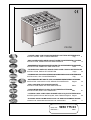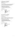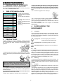
1
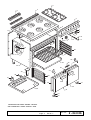
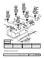
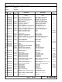
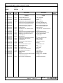
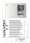
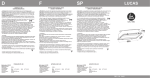
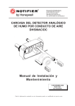
SPARE PARTS CATALOGUE CATALOGO PARTI DI RICAMBIO ELECTROLUX PROFESSIONAL Modular Platform CUCINA GAS CON FORNO GRANDE CAPACITA GAS COOKER WITH LARGE CAPACITY OVEN Viale Treviso, 15 33170 Pordenone - Italy Fax: +39 0434-380577 PNC 168 006 168 806 Pag. Pag. Model Ref. Page Notes RCF/G9 MCF/G9 a b 1-2-3 1-2-3 Gas cooker with large oven Electrolux Gas cooker with large oven Zanussi 1 2 Brand / Marchio : Factory code: Indice Index Piano cottura e forno Componenti gas Cooker top and oven Gas components Zanussi - Electrolux 7PDN From ser. nr. / Da Ser. Nr.:810... Ed. 04 11 Doc. Nr.: 2 - 04 0 06 4 3 1 5 6 7 17 8 9 12 13 14 16 10 11 15 18 20 19 21 23 22 25 24 40 26 27 39 38 30 28 37 30 31 29 32 36 33 34 35 CUCINA GAS CON FORNO GRANDE CAPACITA GAS COOKER WITH LARGE CAPACITY OVEN From ser. nr. / Da Ser. Nr.:810... Page: 1 Ed. 04 11 Doc. Nr.: 2 - 04 0 06 ø100 51 52 53 54 55 57 61 59 56 60 58 62 61 65 63 * 67 68 64 * 66 67 68 71 70 * 69 72 75 * 73 76 74 77 87 86 * 79 85 * 59215 n˚ 27 G.N. 59216 n˚ 14 G.P.L. 75 * 02865 ø 2,30 G.N.cat. "H-E-L" 59363 ø 2,50 G.N.cat. "L L" 56470 ø 1,45 G.P.L.30-37mbar 59364 ø 1,30 G.P.L.50 mbar 78 84 * 82 83 70 05003 ø 1,30 G.N.cat. "H-E-L" 52607 ø 1,40 G.N.cat. " L L" 56743 ø 0,80 G.P.L.30-37mbar 02947 ø 0,70 G.P.L.50 mbar 79 80 81 ø 100 64 * 56793 ø 1,80 G.N.cat. "H-E-L" 66 ø 100 * 02909 ø 0,95 G.N. cat."H-E-L" A2301 ø 1,95 G.N.cat. " L L" A2650 ø 1,20 G.P.L.30-37mbar 59328 ø 1,05 G.P.L.50 mbar 02902 ø 1,05 G.N. cat."L L" 02904 ø 0,60 G.P.L.30-37mbar 02911 ø 0,55 G.P.L.50 mbar CUCINA GAS CON FORNO GRANDE CAPACITA GAS COOKER WITH LARGE CAPACITY OVEN From ser. nr. / Da Ser. Nr.:810... Page: 2 Ed. 04 11 Doc. Nr.: 2 - 04 0 06 CUCINA GAS CON FORNO GRANDE CAPACITA GAS COOKER WITH LARGE CAPACITY OVEN PNC 168006 168806 Pos 1 3 4 5 6 7 8 9 Factory Code Model RCF/G9 MCF/G9 Ref. a b 6 Dgt Code Descrizione Description Pagina 1 Page 1 Ref. / Notes 0523847400 0830883800 0870829004 0870828804 0510816700 0870829305 0870829105 0523849605 0541807401 0541807401 0548841400 0548841500 0516837002 004998 005005 * * 002807 006224 006232 * 059257 059257 004246 004329 005000 * GRIGLIA CAMINO ELECTROLUX GRIGLIA CAMINO ZANUSSI RIPIANO 6 FUOCHI ELECTROLUX RIPIANO 6 FUOCHI ZANUSSI GRIGLIA BIFUOCO CRUSCOTTO ELECTROLUX CRUSCOTTO ZANUSSI FIANCO DESTRO INDICE PER MANOPOLA ELECTROLUX INDICE PER MANOPOLA ZANUSSI MANOPOLA X RUB.GAS ELECTROLUX MANOPOLA X RUB.GAS ZANUSSI NASELLO CHIUSURA PORTA NASELLO CHIUSURA PORTA GRID CHIMNEY, ELECTROLUX GRID CHIMNEY, ZANUSSI 6 BURNER TOP ELECTROLUX 6 BURNER TOP ZANUSSI DOUBLE GRID OPEN BURNER CONTROL PANEL ELECTROLUX CONTROL PANEL ZANUSSI RIGHT SIDE PANEL INDEX, KNOB ELECTROLUX INDEX, KNOB ZANUSSI KNOB, GAS TAP ELECTROLUX KNOB, GAS TAP ZANUSSI CATCH CATCH 0835834900 0638839402 0548841800 0548841900 0518801801 0189068003 002605 002816 0A5295 004295 004336 053342 059446 * ACCENDITORE COPERTURA ACCENDITORE CAVETTO ACCENSIONE MANOPOLA FORNO GAS ELECTROLUX MANOPOLA FORNO GAS ZANUSSI MOLLA PER MARCHIO GUARNIZIONE FORNO GUARNIZIONE SILICONE-CALZAVETRO IGNITER - PIEZO COVER, IGNITER CABLR, IGNITER KNOB, GAS OVEN ELECTROLUX KNOB, GAS OVEN ZANUSSI SPRING, LABEL OVEN GASKET OVEN GASKET 0541802701 0523849801 0507859001 0214584201 0874894801 0830879902 0524851100 0523849404 0835850001 002449 * 059219 066823 004984 004988 * 0C1535 006251 004990 * 058989 * TAPPO SCHIENALE GRIGLIETTA PROTEZIONE BULBO MOLLA BULBO SUPPORTO GRIGLIE DESTRO SUPPORTO GRIGLIE SINISTRO SUPPORTO GRIGLIE GRIGLIA FORNO SUOLA FORNO CONTROPORTA DESTRA CONTROPORTA DESTRA SERRATURA A RULLINO SERRATURA A RULLINO TAP REAR PANEL GRID, BULB SPRING BULB RIGHT GRID SUPPORT LEFT GRID SUPPORT GRID SUPPORT OVEN GRID OVEN PLATE RIGHT INNER DOOR RIGHT INNER DOOR DOOR NEEDLE DOOR NEEDLE 0830804203 0523849504 0525896100 0525896000 0523849005 0523849305 0514884101 0524850905 0527809301 0527809201 0806801400 0523849705 006400 004992 * 004993 005004 004989 * 004991 * 006229 * * * 004249 * GUARNIZIONE CENTRALE FORNO CONTROPORTA SINISTRA CONTROPORTA SINISTRA MANIGLIA FORNO ELECTROLUX MANIGLIA FORNO ZANUSSI PORTA DESTRA PORTA DESTRA PORTA SINISTRA PORTA SINISTRA BOCCOLA PER PERNO FONDO SUPPORTO SINISTRO BRUCIATORE SUPPORTO DESTRO BRUCIATORE PIEDE 1"3/4 INOX - FLANGIA QUADRA FIANCO SINISTRO GASKET, CENTRAL OVEN DOOR LEFR INNER DOOR LEFR INNER DOOR HANDLE, OVEN DOOR ELECTROLUX HANDLE, OVEN DOOR ZANUSSI RIGHT DOOR RIGHT DOOR LEFT DOOR LEFT DOOR BUSH, PIN DOOR BOTTOM PANEL LEFT SUPPORT BURNER RIGHT SUPPORT BURNER FOOT LEFT PANEL a b a b a b a b a b till s /n336 s ince s /n337 T B 2004-12 10 11 12 13 14 15 a b till s /n336 s ince s /n337 T B 2004-12 16 17 18 19 20 21 22 24 25 till s /n336 till s /n336 s ince s /n337 till s /n336 s ince s /n337 till s /n336 s ince s /n337 T B 2004-12 26 29 30 32 33 34 36 37 38 39 40 From ser. nr. / Da Ser. Nr.:810... Page: 3 Ed. 04 11 Doc. Nr.: till s /n336 s ince s /n337 a b till s /n336 s ince s /n337 till s /n336 s ince s /n337 2 - 04 0 06 CUCINA GAS CON FORNO GRANDE CAPACITA GAS COOKER WITH LARGE CAPACITY OVEN PNC 168006 168806 Pos Factory Code Model RCF/G9 MCF/G9 Ref. a b 6 Dgt Code Descrizione Description Pagina 2 Page 2 Ref. / Notes 51 0510812701 002443 SPARTIFIAMMA DIAM.100 FLAME SPREADER 52 0510808701 056748 CORONA D. 100 BRUCIATORE GEAR BURNER 53 0830826503 004239 ASS. BRUCIATORE DIAM.100 BURNER 54 0543802501 054094 GUARNIZIONE BRUCIATORE DIAM.100 GASKET, BURNER 55 0806808000 * CONDUTTURA POSTERIORE DESTRA RIGHT REAR BURNER PIPE 56 0806807900 * CONDUTTURA ANTERIORE DESTRA RIGHT FRONT BURNER PIPE 57 0806808300 * CONDUTTURA POST. CENTRALE CENTRAL REAR BURNER PIPE 58 0853819502 * CONDUTTURA ANT.DESTRA RIGHT FRONT BURNER PIPE 59 0830852802 058332 TERMOCOPPIA THERMOCOUPLE 60 0506832502 058331 PIASTRINA ELETTR./TERMOCOPPIA PLATE, IGNITOR - THERMOCOUPLE 61 0515825500 053448 AREATORE AREATOR 62 0806808200 * 63 0853820000 004257 RUBINETTO GAS TERMOST. FORNO THERMOSTATIC GAS TAP, OVEN 65 0853819900 004237 RUBINETTO GAS FUOCHI APERTI GAS TAP, OPEN BURNER CONDUTTURA POSTERIORE SINISTRA LEFT REAR BURNER PIPE 67 0215073101 060325 BICONO DIA.10 DOUBLECONE 68 0514829301 0A2125 DADO M16X1,5 NUT 69 0806808100 * CONDUTTURA ANTERIORE SINISTRA LEFT FRONT BURNER PIPE 72 0506833401 054029 GUARNIZIONE PER UGELLO GASKET, NOZZLE 73 0511805401 059250 PORTAUGELLO NOZZLE HOLDER 74 0214105101 020997 CONTRODADO PORTAUGELLO NUT NOZZLE HOLDER 76 0830827102 054085 AREATORE AREATOR 77 0830805400 002513 BRUCIATORE FORNO 8,5 KW OVEN BURNER 8.5kW 78 0830863100 059379 BRUCIATORE PILOTA PILOT 80 0517808700 059161 BICONO DIA.4 DOUBLE CONE 81 0214164400 052125 RACCORDO M10X1 PIPE FITTING 82 0830863300 059380 ELETTRODO DI ACCENSIONE IGNITOR 83 0214164101 057960 RACCORDO FISS. CANDELA PIPE FITTING 84 0830853101 051119 TERMOCOPPIA THERMOCOUPLE 85 0853839201 * RIBALTA GAS INLET PIPE 86 0806808402 * CONDUTTURA VALVOLA-BRUCIATORE GAS PIPE, VALVE - BURNER 87 0517857400 * CONDUTTURA PILOTA PILOT PIPE * 0835852401 006422 REGOLATORE DI PRESSIONE GAS PRESSURE GAUGE From ser. nr. / Da Ser. Nr.:810... Page: 4 Ed. 04 11 Doc. Nr.: 2 - 04 0 06 H PR 700 - CUCINE A GAS CON FORNO GRANDE PER COTTURA DIFFERENZIATA INSTALLAZIONE, USO E MANUTENZIONE Pag. 5 - GAS COOKERS WITH LARGE CAPACITY OVEN FOR DIFFERENTIAL COOKING INSTALLATION, OPERATION AND MAINTENANCE Page 13 - GASHERDE MIT GROSSKAPAZITÄTSOFEN FÜR DIFFERENZIERTEGARUNGEN INSTALLATION, GEBRAUCH UND WARTUNG Seite 21 - FOURNEAUX A GAZ AVEC GRAND FOUR POUR CUISSON DIFFERENCIEE INSTALLATION, EMPLOI ET ENTRETIEN Page 29 - COCINAS A GAS CON HORNO DE GRAN CAPACIDAD PARA COCCION DIFERENCIADA INSTALACION, USO Y MANTENIMIENTO Pág. 37 - GASFORNUIZEN MET GROTE OVEN VOORGEDIFFERENTIEERDE BEREIDING INSTRUCTIES VOOR INSTALLATIE, GEBRUIK EN ONDERHOUD Pagina 45 - SPIS, GAS, MED STOR UGNSKAPACITET INSTALLATION, BRUG OG VEDLIGEHOLDELSE Sidan 53 - GASKOMFUR MED STOR OVN TIL DIFFERENTIALSTEGNING INSTALLATION, DRIFT OCH UNDERHÅLL Side 61 - COZINHA A GÁS COM FORNO GRANDE PARA COCÇÃO DIFERENCIADA INSTRUCÇOES PARA A INSTALAÇÃO, USO E MANUTENÇÃO Pagina - ÊÏÕÆÉÍÅÓ ÁÅÑÉÏÕ ÌÅ ÌÅÃÁËÏ ÖÏÕÑÍÏ ÃÉÁ ÄÉÁÖÏÑÏÐÏÉÇÌÅÍÏ ØÇÓÉÌÏ ÏÄÇÃÉÅÓ ÃÉÁ ÔÇÍ ÅÃÊÁÔÁÓÔÁÓÇ ÊÁÉ ÃÉÁ ÔÇÍ ×ÑÇÓÇ DOC. NO. EDITION 1 Óåëßäá 5958 775 03 9904 69 77 DICHIARAZIONE DI CONFORMITÀ ELECTROLUX PROFESSIONAL SPA Viale Treviso 15 33170 PORDENONE Dichiara sotto la propria autorità che le macchine appartenenti a questa documentazione, descritta nella targhetta di identificazione, sono conforme alle seguenti disposizioni legislative: - European Directive 73/23/CEE (L.V.D.) - European Directive 89/336/CEE (E.M.C.) - European Directive 93/68/CEE (Amendment) - European Directive 90/396/CEE (Gas Directive) - Approval: VDE Data: Pordenone 02.03.1998 Nome: Pietro Menza (Responsabile Stabilimento) DECLARATIONE OF CONFORMITY ELECTROLUX PROFESSIONAL SPA Viale Treviso 15 33170 PORDENONE Declares on own authority that the machine present in this documentation, described in the identification plate, conforms to the legislative directions of the directive: - European Directive 73/23/CEE (L.V.D.) - European Directive 89/336/CEE (E.M.C.) - European Directive 93/68/CEE (Amendment) - European Directive 90/396/CEE (Gas Directive) - Approval: VDE Date: Pordenone 02.03.1998 Name: Pietro Menza (Responsabile Stabilimento) 2 IT GB DE FR BE ES NL SE DK PT GR BE SCHEMI DI INSTALLAZIONE INSTALLATION DIAGRAM INSTALLATIONSPLAN SCHEMAS D'INSTALLATION ESQUEMA PARA LA INSTALACIÓN INSTALLATIESCHEMA INSTALLATIONSRITNING INSTALLATIONSDIAGRAM ESQUEMAS DE INSTALAÇAO Ó×ÅÄÉÁÃÑÁÌÌÁÔÁ ÅÃÊÁÔÁÓÔÁÓÇÓ 3 168006 168406 168806 Fig. 1 IT H - Attacco gas Ø 1/2" M ISO 7/1 GB - IE H - Gas connection inlet Ø 1/2" M ISO 7/1 DE - AT- CH H - Gasanschluß Ø 1/2" M ISO 7/1 FR - BE H - Entrée gaz Ø 1/2" M ISO 7/1 ES H - Conexión de gas Ø 1/2" M ISO 7/1 NL - BE H - Aansluiting gas Ø 1/2" M ISO 7/1 SE H - Gasanslutning Ø 1/2" M ISO 7/1 DK H - Tilslutning af gas Ø 1/2" M ISO 7/1 PT H - Ligação gás Ø 1/2" M ISO 7/1 GR H - Óýíäåóç áåñßïõ Ø 1/2" M ISO 7/1 1 4 GAS COOKERS INSTRUCTIONS FOR INSTALLATION AND USE (for the UK) CONTENTS Pagina - Declaration of conformity .................................................................................................... 2 Installation diagrams ........................................................................................................... 4 Appliance Identification ..................................................................................................... 13 I. MAIN FEATURES. ................................................................................................ 14 1. 2. 3. 4. Description of appliance .................................................................................................... 14 Table 1: Technical data ..................................................................................................... 14 Precautions ....................................................................................................................... 14 Safeguarding the environment .......................................................................................... 14 II. INSTRUCTIONS FOR INSTALLATION. .......................................................................... 15 1. 2. 3. 4. 5. 6. 7. 8. 9. 10. Installation place ............................................................................................................... 15 Positioning ......................................................................................................................... 15 Gas connection ................................................................................................................. 15 Start-up ............................................................................................................................. 16 Conversion to different types of gas .................................................................................. 16 Table 2: Injectors and adjustments/Gas types .................................................................. 17 Operation check ................................................................................................................ 17 Servicing ........................................................................................................................... 17 Troubleshooting ................................................................................................................ 17 Replacement of components ............................................................................................ 18 III. INSTRUCTIONS FOR USE .............................................................................................. 19 1. 2. 3. 4. Introduction ....................................................................................................................... 19 Operation notes ................................................................................................................. 19 Cleaning and servicing ...................................................................................................... 20 Warnings ........................................................................................................................... 20 Appliance identification 13 I. MAIN FEATURES 1. • Only contact the technical service centre authorised by the manufacturer for repairs and only use original spare parts. Failure to comply with the above requirement may jeopardise the safety of the appliance and render the guarantee null and void. • Do not wash the appliance with water jets. DESCRIPTION OF APPLIANCE This booklet describes a number of appliance models. For more detailed information about the model in your possession, refer to "Technical Data" table. 2. TABLE TECHNICAL DATA MODELS 995 mm gas oven GAS CONNECTION ISO 7/1 ø 1/2" M HOB BURNER ø100 (5,5 Kw) (Nr) 6 HOB HEAT INPUT (Kw) 33 POTENZA TERMICA FORNO GAS (Kw) 8,5 NOMINAL HEAT INPUT (Kw) 41,5 GAS CATEGORY II 2H3+ CONSTRUCTION TYPE A1 G20 natural gas inlet pressure - (mbar) 20 G25 natural gas inlet pressure(mbar) - L.P.G. G30/G31 inlet pressure (mbar) 28-30/37 L.P.G. G30 consumption (Kg/h) ** 3,27 G20 natural gas consumption (m3/h) ** 4,39 G25 natural gas consumption (m3/h) ** - 3. Total gas consumption: - Calculated with net calorific power (Hi) at 15°C and 1013.25 mbar ** • Do not use products containing chlorine (bleach, hydrochloric acid etc.) even diluted, to clean steel surfaces. • Do not use corrosive substances (i.e. muriatic acid) to clean the floor under the appliance. • For more information, refer to the chapter on "Care and maintenance". L.P.G. G30 (Hi=45.65 MJoule/kg) Natural gas G20 (Hi=34.02 MJoule/m3) Natural gas G25 (Hi=29.25 MJoule/m3) 4. SAFEGUARDING THE ENVIRONMENT 4.1. Packaging • All the packaging materials used are environmentally friendly. They may be stored at no risk or burnt at an authorised incineration plant. Plastic materials suitable for recycling are marked with the following symbols: polyethylene : external wrapping film, instructions PRECAUTIONS PE • Before installing or using the appliance, carefully read this instructions booklet, in as much as it contains important information concerning the safety, operation and maintenance of the appliance. booklet bag and gas injectors bag polypropylene: top packaging panels and straps pp expanded polystyrene: protective surround elements PS 4.2. Use • The appliance has been designed and perfected under laboratory testing conditions to offer exceptional levels of performance. However, to minimise energy consumption (electricity, gas and water) , we recommend turning the appliance off when not in use for long periods and not using it, for example, with the door open as this may impair the oven's performance. We also recommend preheating the appliance immediately prior to use. • Keep this instructions booklet in a safe place for future consultation by other users or purchasers in the event that the appliance is resold. 4.3. Cleaning • To minimise the emission of pollutants into the environment, we recommend cleaning the appliance (externally and, where necessary, internally) with products which are at least 90% biodegradable. Important: Installation and maintenance of the appliance and its conversion to a different gas supply, must only be performed by a qualified installer authorised by the manufacturer. 4.4 Disposal • The appliance must be disposed of properly at the end of its service life. • The appliance is made from 90% recyclable materials (stainless steel, iron, aluminium, galvanised sheet steel, etc.). These materials may therefore be scrapped in accordance with local waste disposal regulations at a conventional recycling plant. • Make the appliance unusable by cutting off the power cord. Also remove any compartment or interior closure device fitted on the appliance to prevent persons from becoming trapped inside. • This appliance is intended for industrial use only and is specifically designed to cook food. Any other use of the appliance is deemed improper. The appliance must only be used by trained staff and must be supervised at all times when in use. • Switch off the appliance if it breaks down or malfunctions. 14 II. INSTRUCTIONS FOR INSTALLATION 1. INSTALLATION PLACE 3. • The appliance must only be installed in adequately ventilated premises. 3.1. WARNINGS • Before installing the appliance, contact the local gas supply authority. • Refer to the technical data and figures shown at the beginning of this instructions manual for the space requirements and connection dimensions of the appliance. • Before connecting the appliance to the gas line, remove the plastic cover from the gas connection on the appliance. • Make sure that the appliance corresponds with the gas supply to which it is connected. If this is not the case, follow the instructions shown in the paragraph " Conversion to different types of gas". • Install the pressure regulator the appliance is supplied with ahead of the appliance. • Figure 3 shows how to install the pressure regulator: - "1-3" gas connection towards the appliance; - "1-2" pressure regulator; - "1-4" gas connection towards the gas supply. • The section of the gas supply pipe must be such as to assure enough gas capacity to be able to operate all appliances connected to the gas line. • The arrow on the pressure regulator indicates the direction of the gas flow. It is convenient to install the pressure regulator horizontally to assure the right outlet pressure. • This models have been projected and certified to be used with natural gas or propane. When natural gas is to be used the pressure regulator on the collector will be set to 8" w.c. (20mbar). 1.1. APPLICABLE STANDARDS Install the appliance in compliance with the safety standards currently in force in the country of use. 2. GAS CONNECTION POSITIONING • The appliance may be installed separately, side by side with other appliances from our range, or mounted on tables. • This appliance is not suitable for built-in installation. • The appliance must be positioned at least 10 cm away from the side and rear walls. • Thermal insulation must be fitted if the appliance is positioned less than 10 cm from the wall, or installed either directly on the floor or on flammable material. • Carefully remove the protective film from the external panels to avoid leaving any trace of glue. Use a suitable diluent to remove any glue residue. • Close the holes on the side of the appliance by means of the plugs supplied. 2.1 JOINING APPLIANCES (fig. 2) • Position the appliances together provisionally; level to the correct height and separate. • Attach the adhesive tape "C" on the edges of the tops to be joined. • Apply a bead "D" of special sealant (ref. code 059611) on the upper edge of the side. • Join the appliances and fix by means of holes "A" and "B" using M5x20 screws and secure by means of nuts and washers. • Remove excess sealant by means of a spatula and remove the adhesive tape. 3 • Once the appliance has been installed, check for gas leaks at connection points using a soapy water solution. • Installation and maintenance (of gas, electric current etc.) must only be carried out by the local power supply authority or an authorized installer. 3.2. GAS EXHAUST FOR TYPE "A1" APPLIANCES It is a good idea to install "A1" type appliances under an extractor hood to ensure the removal of gases and steam generated during cooking. 2 Warning! The sealant begins polymerization starting from the external surface: it is recommended not to touch the sealant in the first three hours after application in order to avoid any trimming. 15 4. START-UP 4.1 CHECKING THE NOMINAL HEAT INPUT The nominal heat input of the appliance must be checked by an authorized installer or the local gas supply authority in accordance with the instructions shown below, for the installation of new appliances, conversion of existing appliances to a different gas supply and servicing. The heat input cannot be readjusted after this check. Heat input: M AX M IN . burner ø100 Gas oven 5 ,5 k W 8 ,5 k W 1 ,3 5 k W 2 ,5 k W Type of gas Pressure mbar G20 natural gas L.P.G. G30/G31 Norm. 20 28-30/37 M in. 17 20/25 M ax 25 35/45 Once the inlet pressure has been checked, remove the pressure gauge and tighten the sealed bolt. 5. CONVERSION TO DIFFERENT TYPES OF GAS For conversion to a different gas supply, refer to the injector table below and proceed as follows: - Remove the control panel. The appliance's maximum and minimum heating settings are obtained by measuring the correct inlet pressure and by making sure that the injectors used correspond to the application in question. The instructions for these checks are indicated below. Once the minimum and maximum heating settings have been checked, test the operation of the appliance in accordance with the instructions shown in paragraph 7. 5.1 REPLACEMENT OF THE HOB MAIN BURNER INJECTOR (fig. 5) • Slacken screw "D", slide air inlet sleeve "C" up as far as it will go and fix with screw "D". • Unscrew injector "B" using a straight box end wrench model 12x13 UNI 6739 - ISO 3318 - DIN 837 with 12 mm reach and replace with a version according to the type of gas used, in accordance with the specifications in the table 2 below. • The injector diameter is indicated in hundredths of millimetres on the injector body. 4.2. CHECKING THE GAS INLET PRESSURE (Fig. 4) Check whether the appliance is compatible with the type of gas supplied according to what is indicated on the data plate. If it does not correspond, follow the instructions in the paragraph "Adaptation to a different type of gas". The pressure regulator have to set at 4" w.c. (10mbar) for natural gas and 10" w.c. (25mbar) for propane gas. To check the manifold pressure: 1) Turn all thermostats and burner valves to OFF position. 2) Turn main gas valve to entire unit OFF. 3) Remove knobs, control panel and locate 1/8" plug in manifold. 4) Remove plug and install a fitting appropriate to connect a pressure gauge. 5) Turn on main gas to unit and light pilots. 6) Turn all burners and ovens (where present) to full ON position and read pressure gauge, then read the pressure value indicated by the gauge (to start pilot flame and burners see paragraph 2.1 of part IV "Instructions for the use"). 7) If the pressure of the connection is more or less than expected values as in the following table, inform immediately your gas company, then set the inlet pressure (acting on the pressure regulator "B" - fig. 4) as indicated in in 8, 9 and 10 steps. Never switch on the appliance before checking that the pressure is at the nominal suitable value in chart below. If the pressure is already on the nominal value, go directly to the step 11. 8) Remove cap from top of regulator. 9) With a screwdriver rotate regulator adjustment screw "clockwise" to increase, or "counterclockwise" to decrease, pressure until pressure gauge shows correct reading. 10) Replace cap of regulator. 11) Repeat step 1 and 2. 12) Remove pressure gauge fitting and replace plug in manifold. 13) Replace valve panels. 5 5.2 REPLACEMENT OF THE HOB MINIMUM SUPPLY INJECTOR. (fig. 7) • Slacken minimum supply adjustment screw "B" on the cock and replace with one corresponding to the gas supply used (tighten fully down). 5.3 CHECKING THE HOB PRIMARY AIR (fig. 5) The primary air flow rate is correct when the flame does not detach when the burner is cold or backfire when the burner is hot. To adjust the primary air flow rate, proceed as follows: • Slacken fixing screw "D" and adjust sleeve "C" to distance "H" as indicated in the table 2 below. • Retighten fixing screw "D". 5.4 REPLACEMENT OF THE OVEN MAIN BURNER INJECTOR (fig. 6) • Remove the oven base. • Slacken screw "A" and unscrew injector "C". • Remove the injector and aerator. • Replace injector "C" with one corresponding to the type of gas used, as indicated in the table below. • The injector diameter is indicated in hundredths of millimetres on the injector body. • Fit injector "C" in aerator "B" and return the assembled unit to its housing. Firmly tighten the injector and screw "A". 4 16 5.5 CHECKING THE OVEN PRIMARY AIR (Fig. 6) • Slacken screw "A" and position aerator "B" at distance "H" as indicated in the table below: • Retighten screw "A". 7. OPERATION CHECK • Ignite the appliance in accordance with the instructions for use • Check the appliance for gas leaks. • Make sure the gas exhaust system functions correctly. • Check ignition and flame uniformity. • Using the instructions manual, explain the operation and maintenance instructions to the user, paying particular attention to the warnings concerning correct use. 5.6 REPLACEMENT OF THE OVEN PILOT BURNER INJECTORS (fig. 7) • Slacken nipple "A" and replace injector "B" with one corresponding to the gas supply used. • The injector diameter is indicated in hundredths of millimetres on the injector body. • Retighten nipple "A". 8. SERVICING All components requiring maintenance may be easily accessible from the front of the appliance, simply by removing the control panel. 5.7 REPLACEMENT OF THE OVEN MINIMUM SUPPLY INJECTOR (fig. 8) • Slacken minimum supply adjustment screw "B" and replace with one corresponding to the type of gas used (tighten fully down). 9. TROUBLESHOOTING The following malfunctions may occur under normal operating conditions. — THE BURNER DOES NOT IGNITE Causes: • Spark electrode incorrectly fixed or poorly connected. • Electric/piezoelectric ignition or spark electrode cable damaged. • Insufficient pressure in gas pipes. • Blocked injector. • Defective gas cock. 8 5.8 GAS CONVERSION PLATE If the appliance is converted to a different gas supply, affix the correct adhesive tag indicating the new gas used. — THE MAIN OR PILOT BURNER GOES OUT WHEN THE IGNITION KNOB IS RELEASED Causes: • Thermocouple insufficiently heated by main or pilot burner. • Defective thermocouple. • Insufficient pressure applied to gas cock knob. • Insufficient pressure at gas cock. • Defective gas cock. 6. TABLE 2: INJECTORS AND ADJUSTMENTS/GAS TYPES MODEL Oven burner ø100 Convector BURNER INJECTOR DATA ø (mm) N° refer. ø (mm) MAX M ai n bur ner i nject o r o f t he co o ki ng t o p P ar agr aph 5.1 N° refer. MIN ø (mm) N° refer. ø (mm) MAX G30/G31 (liquid) 1,2 120 0,6 60 G20 (natural) 1,8 180 0,95 95 N° refer. MIN — THE PILOT BURNER REMAINS IGNITED BUT THE MAIN BURNER DOES NOT IGNITE Causes: • Insufficient pressure in gas pipes. • Blocked injector or defective gas cock. • Burner gas outlet holes clogged. G25 (natural) G30/G31 (liquid) P i l o t bur ner i nject o r o f t he co o ki ng t o p P ar agr aph 5.3 G20 (natural) G25 (natural) M ai n bur ner i nject o r o f t he o ven P ar agr aph 6 .4 G30/G31 (liquid) 1,45 145 0,8 80 G20 (natural) 2,3 230 1,3 130 G25 (natural) P i l o t bur ner i nject o r o f t he o ven P ar agr aph 6 .4 G30/G31 (liquid) n° 14 G20 (natural) n° 27 — TEMPERATURE ADJUSTMENT MALFUNCTION Causes: • Defective thermostat bulb. • Defective gas thermostat cock. • Defective electric thermostat. • Safety thermostat has cut out. G25 (natural) R ep. o f t he bur ner aer at o r o f t he co o ki ng t o p Hei ght " H" S ee P i ct . B es i de R ep. o f t he bur ner o f t he o ven Hei ght " H" S ee P i ct . B es i de G30/G31 (liquid) H = mm 35 G20 (natural) H = mm 7 G25 (natural) G30/G31 (liquid) H = mm 34 G20 (natural) H = mm 35,5 G25 (natural) 6 7 17 11. REPLACEMENT COMPONENTS OF (Only to be carried out by an authorized installer). REMOVE THE TOP CONTROL PANEL: — GAS COCK • Remove the thermocouple. • Remove the gas inlet/outlet connections. — MAIN BURNER • Remove the injector support gas pipe. • Slacken the hob burner fixing screws. — THERMOCOUPLE, SPARK ELECTRODE. • Remove the component fixing brackets and replace. — GAS OVEN THERMOSTAT COCK • Remove the pilot burner pipe and thermocouple. • Remove the gas inlet/outlet connections. • Remove the bulb from its seat by detaching it from inside the oven. REMOVE THE OVEN BASE — MAIN BURNER • Remove the injector support gas pipe and fixing screws. When re-assembling the burner, take care to insert the rear alignment pin in the correct seat. — PILOT BURNER • Remove the oven base via the bottom control panel and inside of the oven. FOR THE INSTALLATION OF COMPONENTS, FOLLOW THE SAME PROCEDURE IN REVERSE ORDER. 18 III. INSTRUCTIONS FOR USE This appliance is intended for industrial use, and must only be used by trained staff. 1. 2.2 TURNING OFF THE HOB (fig. 9) • Turn knob "A" to "OFF". INTRODUCTION • Carefully read this instructions manual, insofar that it contains important information concerning the safety, operation and maintenance of this appliance. • Keep this instructions manual in a safe place for future consultation by other users. • Installation of this appliance and its conversion to a different gas supply, must only be performed by a qualified installer. • Only contact the technical service centre authorized by the manufacturer for repairs and only use original spare parts. Failure to comply with the above instructions may jeopardise the safety of this appliance. • Our appliances have been designed and optimised by means of laboratory tests to guarantee high levels of performance and efficiency. However, to save energy (electricity, gas and water) avoid using the appliance under no-load conditions or conditions that impair optimal operation (e.g. with the doors/lids open). Also, when possible, pre-heat the appliance before use. 2. 9 OPERATION NOTES 2.3 IGNITING THE GAS OVEN (fig. 8) The thermostat cock control knob has the following settings: • This appliance is designed to cook foods in recipients such as saucepans and frying pans. • Any other application is understood to be improper. V C - 2.1 IGNITING THE HOB (fig. 9) The standard cock control knob has three settings: V A B> OFF Pilot ignition Temperature values • Press and rotate counterclockwise knob “C” from the “OFF” to the “pilot ignition” setting. • Press thoroughly knob “C” and at the same time press the push button of the piezoelectric igniter “B” which will ignite the pilot flame. After about 20 seconds release knob “C” and the pilot flame must keep on burning. Should this not happen, repeat the operation. Should there be an emergency, the ignition of the pilot burner can be carried out by hand approaching a flame to the pilot burner keeping knob “C” on “pilot ignition” setting. • The ignition of the main burner is reached by rotating knob “C” counterclockwise so that it corresponds to the desired temperature value. The appliance is equipped with a thermostatic valve that keeps the level of the oven temperature automatically constant. OFF Max. flame Min. flame • Press and rotate counterclockwise knob “A” from the “OFF” to the “max. flame” setting. • Press thoroughly knob “A” and at the same time approach a flame. After about 20 seconds release knob “A” and the pilot flame must keep on burning. Should this not happen, repeat the operation. • To reach the minimum, turn the knob from the “max. flame” to the “min. flame” setting. 2.4 TURNING OFF THE GAS OVEN (fig. 9) • Turn knob "C" to "Pilot ignition" to extinguish the main burner. • Turn knob "C" to "OFF" to extinguish the pilot burner. 19 3. PR 700 - GAS COOKERS CLEANING AND SERVICING • To reduce the emission of harmful substances into the atmosphere, clean the appliance (externally, and internally when necessary) with products featuring over 90% biodegradability. • Dally wash the stainless steel surfaces with soapy lukewarm water, rinse thoroughly and dry carefully. • When cleaning stainless steel do not use detergents containing abrasive substances as well as shavings, scouring pads, brushes or scrapers in common steel since ferrous residue of these can cause rust. Stainless steel wool can be used, wiped in the direction of the satin finish. • Daily clean the burners and the holes of the flame protections from any scales. • When the appliance remains inoperative for long periods of time, observe the following precautions: - close the main gas cock placed upstream from the appliance; - on all the stainless steel surfaces apply a cloth soaked in vaseline oil in order to spread a protective film; - periodically air the premises. • Periodically (at least once a year) have the appliance totally checked. For this purpose, it is recommended to draw up a maintenance contract. 4. MAIN COMPONENTS COOKING TOP • Gas cock "PINTOSSI"-type, SC-PEL 20 S equipped with gas inlet filter • Thermocouple "SIT"-type, mod. 0.290, M8x1 thread • Main burner "CZGI"-type GAS OVEN • Gas termoststic cock "PINTOSSI"-type, mod. 25 ST equipped with gas inlet filter • Pilot burner "SIT"-type, mod. 0.140 WARNINGS • Thermocouple "SIT"-type, mod. 0.200, M8x1 thread • Do not wash the appliance with water jets. • Do not use products containing chlorine (bleach, hydrochloric acid etc.) even diluted, to clean steel surfaces. • Do not use corrosive substances (i.e.: muriatic acid) to clean the floor under the appliance. • Do not modify the aeration supply necessary for combustion. • When scrapping the appliance, observe all regulations governing waste disposal in the country of installation. • Our appliances are manufactured using more than 90 % metal (stainless steel, iron, aluminium, galvanised sheet metal) and therefore these may be recycled in conventional waste recovery sites in compliance with current standards in the country of installation. • Render the appliance completely inoperative by removing the power cable and any other closure device (where fitted) to avoid the risk of persons being trapped inside. • Burner "Polidoro"-type in stainless steel AISI 430 • Piezoelectric igniter "INECO"-type, mod. 6000 20