1
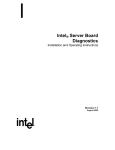
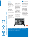
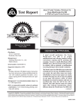
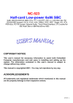
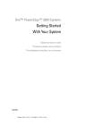
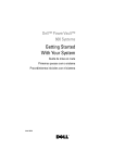
3097P0.book Page 1 Monday, December 6, 1999 10:29 AM
The Dell™ PowerEdge™ 6450 system, which supports up to four Intel® Pentium® III
Xeon™ microprocessors (and future generation Intel microprocessors), is a featurerich, enterprise class server that offers the highest performance, availability, scalability,
manageability, and investment protection features. The PowerEdge 6450 system provides a robust, reliable, rack-optimized platform on which large corporate customers
can deploy their mission critical applications.
This chapter describes the major hardware and software features of the computer
system, provides information about the indicators and controls on the system's front
panel, and discusses connecting external devices to the system.
The PowerEdge 6450 systems offer the following major features:
One to four Intel Pentium III Xeon processors
The Processor Speed option on Page 1 of the System Setup program lists your
system's processor speed. For more information, see Chapter 4, “Using the
System Setup Program.”
The Pentium III Xeon processor includes MMX™ technology designed to handle
complex multimedia and communications software. This processor incorporates
new instructions and data types as well as a technique called single instruction,
multiple data (SIMD) that allows the processor to process multiple data elements
in parallel, thereby improving overall system performance.
support.dell.com
A secondary (L2) cache of 512 kilobytes (KB), 1 megabyte (MB), or 2 MB of static
random-access memory (SRAM) is included within the single-edge contact (SEC)
cartridge that contains the processor. Math coprocessor functionality is internal
to the processor.
Support for symmetric multiprocessing (SMP) is available by installing up to three
more Pentium III Xeon processors. SMP greatly improves overall system performance by dividing processor operations among the independent processors. To
take advantage of this feature, you must use an operating system that supports
Introduction
1-1
3097P0.book Page 2 Monday, December 6, 1999 10:29 AM
multiprocessing, such as Microsoft® Windows NT® 4.0 or Novell® NetWare® 4.2
(and later versions of both).
NOTE: If you decide to upgrade your system by installing additional processors, you
must order processor upgrade kits from Dell. Not all versions of the Pentium III
Xeon processor will work properly as additional processors. The upgrade kit from
Dell contains the correct version of the processor for use as an additional processor, as well as instructions for performing the upgrade. The additional processors
must have the same internal operating frequency as the initial processors.
A minimum of 256 MB of system memory, upgradable to a maximum of
8 gigabytes (GB) by installing combinations of 64-, 128-, 256-, and 512-MB synchronous dynamic RAM (SDRAM) in the 16 dual in-line memory module (DIMM)
sockets on the memory board.
A basic input/output system (BIOS) that resides in flash memory on the Peripheral Component Interconnect (PCI) bus and can be upgraded if required.
Four hot-pluggable small computer system interface (SCSI) 1-inch hard-disk drives.
Three redundant, hot-pluggable power supplies and power-supply paralleling
board (PSPB).
NOTE: A minimum of two power supplies are needed to run the system.
Four redundant system cooling fans.
The system board includes the following integrated features:
Seven PCI connectors; two 64-bit 66 MHz, four 64-bit 33 MHz, and one 32-bit
33 MHz.
A video graphics array (VGA)-compatible video subsystem with an ATI Rage IIc
super VGA (SVGA) video controller. This video subsystem contains 4 MB of
SDRAM video memory (nonupgradable). Maximum resolutions are 1024 x 768
with 256 colors noninterlaced. In 800 x 600 and 640 x 480 resolutions, 16.7 million colors are available for true-color graphics.
A National Semiconductor PC97317 super input/output (I/O) controller that controls the bidirectional parallel port, two serial ports, the real-time clock (RTC), and
the diskette drive in the externally accessible front bay.
The parallel port can be set to operate in the following modes via the Parallel
Mode option in the System Setup program: output-only (AT-compatible) or
bidirectional (Personal System/2 [PS/2]-compatible).
1-2
One dual-channel Adaptec AIC-7899 Ultra3 (Ultra160) SCSI host adapter that supports the internal SCSI hard-disk drives via a SCSI backplane board and special
SCSI hard-disk drive carriers. The SCSI backplane automatically configures SCSI
ID numbers and SCSI termination on individual hard-disk drives.
Server management circuitry that monitors operation of the system fans as well
as critical system voltages and temperatures. The server management circuitry
works in conjunction with the optional HP OpenView Network Node Manager
Special Edition (NNM SE) and the Dell OpenManage™ Hardware Instrumentation
Package (HIP) software package.
Dell PowerEdge 6450 Systems User’s Guide
3097P0.book Page 3 Monday, December 6, 1999 10:29 AM
System board support for the Dell OpenManage Remote Assistant when the
optional Dell Remote Assistant Card version 2 (DRAC 2) is installed, which provides additional local and remote server management.
A PS/2-style keyboard port and a PS/2-compatible mouse port.
A 3.5-inch diskette drive and an integrated drive electronics (IDE) CD-ROM drive;
a SCSI hard-disk drive installed in slot 0.
A dual USB port.
An integrated Intel Pro/100+ network interface controller (NIC).
The following software is included with your Dell system:
Video drivers for displaying many popular application programs in high-resolution
modes.
SCSI device drivers that allow your operating system to communicate with
devices attached to the integrated SCSI subsystem.
The System Setup program for quickly viewing and changing the system configuration information for your system.
The Resource Configuration Utility (RCU), which automatically configures
installed PCI expansion cards.
Enhanced security features available through the System Setup program including a user password and a supervisor password.
Diagnostics for evaluating your system's components and devices. For information
on using the system diagnostics, see Chapter 2, "Using the Dell OpenManage
Server Assistant CD," found later in this document, or Chapter 5, "Running the Dell
Diagnostics," in your Installation and Troubleshooting Guide.
Dell supports the following network operating systems for use on PowerEdge 6450
systems:
support.dell.com
Windows NT Server 4.0
Windows NT Server 4.0, Enterprise Edition
NetWare 4.2
NetWare 5
Windows® 2000 operating systems
Introduction
1-3
3097P0.book Page 4 Monday, December 6, 1999 10:29 AM
The following controls and indicators are behind the external drive door on the system's front panel (see Figure 1-1):
The power button controls the output power delivered to the system board from
the power supply.
The green power indicator in the center of the power button lights up when the
power supply is turned on and the system is receiving DC power.
NOTE: The power button is recessed into the system's front panel to prevent
accidentally turning off the computer and losing valuable data.
The following indicators are on the system's front panel (see Figure 1-1):
The green fan/temperature status indicator blinks amber when a fan failure is
detected or temperature is out of bounds.
The green power-supply status indicator blinks amber if a fault is detected with
any of the power supplies or any system voltages.
The three indicator lights on each of the SCSI hard-disk drive carriers provide the following information (see Figure 1-2):
The green hard-disk drive online indicator lights up when the hard-disk drive is
receiving power.
The green hard-disk drive activity indicator lights up when data is being transferred to or from the hard-disk drive.
The amber hard-disk drive failure indicator blinks if a hard-disk drive failure is
detected
hard-disk drive
status indicator
fan/temperature
status indicator
power supply
status indicator
1-4
Dell PowerEdge 6450 Systems User’s Guide
3097P0.book Page 5 Monday, December 6, 1999 10:29 AM
hard-disk drive
failure indicator
hard-disk
drive activity
indicator
hard-disk drive
online indicator
You can connect various external devices, such as a mouse and printer, to the I/O
ports and connectors on the system's back panel (see Figure 1-3). The system BIOS
detects the presence of external devices when you boot or reboot your system.
When connecting external devices to your system, follow these guidelines:
Check the documentation that came with the device for specific installation and
configuration instructions.
For example, most devices must be connected to a particular I/O port or connector to operate properly. Also, external devices such as a mouse or printer usually
require you to load software files called device drivers into memory before they
will work. These device drivers help the system recognize an external device and
direct its operation. Device drivers of this type are normally included with your
operating system software.
support.dell.com
Always attach external devices while your system is turned off. Then turn on any
external devices before turning on the system unless the documentation for the
device specifies otherwise. (If the system does not seem to recognize the
device, try turning on the system before turning on the device.)
Introduction
1-5
3097P0.book Page 6 Monday, December 6, 1999 10:29 AM
hot-plug LED
indicators (7)
expansion
slots (7)
parallel port
connector
optional SCSI
connector ports (2)
video connector
AC power
receptacle
mouse
connector
serial port 1 connector
serial port 2 connector
NIC connector
keyboard
connector
USB connectors (2)
For information about enabling, disabling, or configuring I/O ports and connectors, see
Chapter 4, "Using the System Setup Program," or Chapter 5, "Using the Resource
Configuration Utility." For detailed descriptions and illustrations of each port and connector on the I/O panel, see Appendix B, "I/O Ports and Connectors."
A keylock behind the door on the front bezel prevents unauthorized access to the hotpluggable hard-disk drives (see Figure 1-1). A second lock on the back of the unit prevents the top cover from being removed.
The PowerEdge 6450 system also includes a system intrusion switch that signals
appropriate server management software if the top cover is opened.
!
"
If at any time you do not understand a procedure described in this guide, or if your
system does not perform as expected, Dell provides a number of tools to help you.
For more information on these help tools, see Chapter 11, "Getting Help," in your
Installation and Troubleshooting Guide.
1-6
Dell PowerEdge 6450 Systems User’s Guide