1
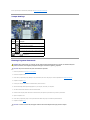
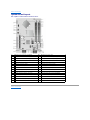
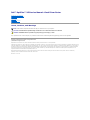
Dell™ OptiPlex™ XE Service Manual—Small Form Factor
Working on Your Computer
Removing and Replacing Parts
Specifications
Diagnostics
System Setup
System Board Layout
Notes, Cautions, and Warnings
NOTE: A NOTE indicates important information that helps you make better use of your computer.
CAUTION: A CAUTION indicates potential damage to hardware or loss of data if instructions are not followed.
WARNING: A WARNING indicates a potential for property damage, personal injury, or death.
If you purchased a Dell™ n Series computer, any references in this document to Microsoft® Windows® operating systems are not applicable.
Information in this document is subject to change without notice.
© 2010 Dell Inc. All rights reserved.
Reproduction of this material in any manner whatsoever without the written permission of Dell Inc. is strictly forbidden.
Trademarks used in this text: Dell, the DELL logo, and OptiPlex are trademarks of Dell Inc.; Intel, Pentium, Celeron, a n d Core are either trademarks or registered trademarks of Intel
Corporation; Bluetooth is a registered trademark owned by Bluetooth SIG, Inc. and is used by Dell under license; TouchStrip is a trademark of Zvetco Biometrics, LLC; Blu-ray Disc is
a trademark of the Blu-ray Disc Association; Microsoft, Windows, Windows Server, Windows Vista, and the Windows Vista start button are either trademarks or registered trademarks
of Microsoft Corporation in the United States and/or other countries; Adobe, the Adobe logo, and Adobe Flash Player are trademarks of Adobe Systems Incorporated; Wi-Fi is a
registered trademark of Wireless Ethernet Compatibility Alliance, Inc.
Other trademarks and trade names may be used in this document to refer to either the entities claiming the marks and names or their products. Dell Inc. disclaims any
proprietary interest in trademarks and trade names other than its own.
March 2010 Rev. A00
Back to Contents Page
System Setup
Dell™ OptiPlex™ XE Service Manual—Small Form Factor
Overview
Entering System Setup
System Setup Options
Boot Sequence
Booting to a USB Device
Booting to a USB Device
Password Protection
Jumper Settings
Clearing Forgotten Passwords
Clearing CMOS Settings
Overview
Use System Setup to:
l
Change the system configuration information after you add, change, or remove any hardware in your computer
l
Set or change a user-selectable option such as the user password
l
Read the current amount of memory or set the type of hard drive installed
Before you use System Setup, it is recommended that you write down the System Setup screen information for future reference.
CAUTION: Unless you are an expert computer user, do not change the settings for this program. Certain changes can make your computer work
incorrectly.
Entering System Setup
1.
Turn on (or restart) your computer.
2.
When the DELL™ logo is displayed, watch for the F12 prompt to appear. 3.
Press <F12> immediately. The Boot Menu appears.
4.
Use the up and down arrow keys to select System Setup and then press <Enter>.
NOTE: The F12 prompt indicates that the keyboard has initialized. This prompt can appear very quickly, so you must watch for it to display, and then
press <F12>. If you press <F12> before you are prompted, this keystroke will be lost.
5.
If you wait too long and the operating system logo appears, continue to wait until you see the Microsoft® Windows® desktop. Then, shut down your
computer and try again.
System Setup Screen
The System Setup screen displays current or changeable configuration information for your computer. Information on the screen is divided into two areas: the
menu, and the main window.
Options List — This field appears on the left side of the
system setup window. The field is a scrollable list
containing features that define the configuration of
your computer, including installed hardware, power
conservation, and security features.
Option Field — This field contains
information about each option. In
this field you can view your current
settings and make changes to your
settings.
Use the Tab and Up/Down arrow
keys on your keyboard to navigate
or click to navigate using the
mouse.
System Setup Options
NOTE: Depending on your computer and installed devices, the items listed in this section may not appear, or may not appear exactly as listed.
General
System Board
Displays the following information:
System information: Displays BIOS Info, System Info, and the Service Tag.
Memory information: Displays Installed Memory, Usable Memory, Memory Speed, Memory Channel Mode, and Memory
Technology.
Processor information: Displays the Processor Type, Processor Speed, Processor Bus Speed, Processor L2 cache, Processor ID.
PCI information: Displays available slots on the system board.
l
l
l
l
Date/Time
Displays the system date and time. Changes to the system date and time take effect immediately.
Boot Sequence Specifies the order in which the computer attempts to find an operating system from the devices specified in this list.
Drives
Enables or disables the floppy drive connector on the system board.
Diskette drive
Disable
Enable
l
l
Configures the operating mode of the integrated hard drive controller to:
SATA Operation
RAID Autodetect/AHCI (default)
RAID Autodetect/ATA
RAID On/ATA
Legacy
l
l
l
l
S.M.A.R.T. Reporting Enables or disables integrated drive errors to be reported during system startup.
This option is disabled by default.
Enables or disables the SATA or ATA drives connected to the system board.
Drives
System Configuration
Enables or disables the integrated network card. You can set the integrated NIC to:
Integrated NIC
l
Integrated NIC 2
l
l
Enable (default)
Disable
Enable with PXE
Enables or disables the integrated USB controller. You can set the USB controller to:
USB Controller
l
l
l
Enable (default)
Disable
No boot
Identifies and defines the serial port settings. You can set the serial port to:
Serial Port #1
l
Serial Port #2
l
l
l
Disable
Auto (default)
COM1
COM3
NOTE: Auto, the default setting, automatically configures a connector to a particular designation (COM1 or COM3).
Miscellaneous Devices Enables or disables the following onboard devices:
l
l
l
l
l
l
Front USB
Rear Dual USB (under NIC1 and powered USB)
Rear Dual USB (under NIC2 and powered USB)
PCI slots
Audio
WiFi NIC slot
Video
Primary Video Specifies which video controller is primary when two video controllers are present on the computer.
Auto (default)
Onboard/PEG
l
l
Performance
Multi Core Support Specifies whether one or all the cores of the processor will be enabled.
NOTE: The performance of some applications improve with additional cores.
Intel® SpeedStep™
Enables or disables the Intel SpeedStep mode.
This option is disabled by default.
C States Control
Enables or disables additional processor sleep states.
This option is disabled by default.
Limit CPUID Value
Enables or disables the CPUID limit.
This option is disabled by default.
Virtualization Support
Virtualization
Enables or disables Intel® Virtualization technology.
This option is disabled by default.
VT for Direct
I/O
Enables or disables the Virtual Machine Monitor (VMM) from utilizing the additional hardware capabilities provided by Intel Virtualization
technology for direct I/O.
This option is disabled by default.
Security
Administrative
Password
Provides restricted access to the computer's system setup program in the same way that access to the system can be restricted
with the System Password option.
This option is not set by default.
System Password
Displays the current status of the system's password security feature and allows a new system password to be assigned and
verified.
This option is not set by default.
Password Changes
Enables or disables the user from changing the system password without the administrative password.
This option is enabled by default.
CPU XD Support
Enables or disables the execute disable mode of the processor.
This option is enabled by default.
Computrace(R)
Enables or disables the optional Computrace® service designed for asset management.
You can set this option to:
l
l
l
Deactivate (default)
Disable
Activate
SATA-0 Password
Displays the current status of the password set for the hard drive connected to the SATA-0 connector on the system board.
SATA-1 Password
You can also set a new password. This option is not set by default.
NOTE: The system setup program displays a password for each of the hard drives connected to your system board.
Power Management
AC Recovery
Determines how the system responds when AC power is re-applied after a power loss. You can set the AC Recovery to:
l
l
l
Power Off (default)
Power On
Last State
Auto On Time
Sets time to automatically turn on the computer.
Time is kept in the standard 12-hour format (hours:minutes:seconds).
Change the startup time by typing the values in the time and AM/PM fields.
NOTE: This feature does not work if you turn off your computer using the switch on a power strip or surge protector or if Auto
Power On is set to disabled.
Low Power Mode
Enables or disables low power mode.
This option is disabled by default.
NOTE: When low power mode is enabled, the integrated network card is disabled.
Remote Wakeup
Allows the system to power up when a network interface controller receives a wake up signal. You can set Remote Wakeup to:
l
l
l
Suspend Mode
Disable (default)
Enable
Enable with Boot NIC
Sets the power management suspend mode to:
l
l
Fan Control Override
S1
S3 (default)
Controls the speed of the system fan.
NOTE: When enabled, the fan runs at full speed.
Maintenance
Service Tag
Displays the Service Tag of your computer.
System Management
Enables or disables system management.
l
l
Disable
DASH/ASF 2.0
Allows you to create a system asset tag if an asset tag is not already set.
Asset Tag
This option is not set by default.
Controls the SERR Message mechanism.
SERR Messages
This option is enabled by default.
Some graphics cards require the SERR Message mechanism be disabled.
Watchdog Timer Support Enables or disables Watchdog support.
Post Behavior
Fast Boot
When enabled (default), your computer starts more quickly because it skips certain configurations and tests.
NumLock LED
Enables or disables the NumLock feature when your computer starts.
When enabled (default), this option activates the numeric and mathematical features shown at the top of each key. When disabled, this
option activates the cursor-control functions labeled on the bottom of each key
POST Hotkeys
Allows you to specify the function keys to display on the screen when the computer starts.
l
l
Keyboard
Errors
Enable F2 = Setup (enabled by default)
Enable F12 = Boot menu (enabled by default)
Enables or disables keyboard error reporting when the computer starts.
This option is enabled by default.
System Logs
BIOS Events Displays the system event log and allows you to:
l
l
Clear Log
Mark all Entries
Boot Sequence
This feature allows you to change the Boot Device Property for devices.
Option Settings
l
Onboard USB Floppy Drive — The computer attempts to boot from the floppy drive.
l
Onboard SATA Hard Drive — The computer attempts to boot from the hard drive.
l
USB Device — The computer attempts to boot from a removable device, such as a USB key.
l
CD/DVD — The computer attempts to boot from the disc drive.
Changing the Boot Sequence for the Current Boot
You can use this feature, for example, to restart your computer to a USB device, such as a floppy drive, memory key, or optical drive.
1.
If you are booting to a USB device, connect the USB device to a USB connector.
2.
Turn on (or restart) your computer.
3.
When F12 = Boot Menu appears in the upper-right corner of the screen, press <F12>. If you wait too long and the operating system logo appears, continue to wait until you see the Microsoft Windows desktop, then shut down your
computer and try again.
4.
The Boot Menu appears, listing all available boot devices.
5.
Use the arrow keys to select the appropriate device (for the current boot only).
NOTE: To boot to a USB device, the device must be bootable. To ensure that a device is bootable, check the device documentation.
Changing the Boot Sequence for Future Boots
1.
Enter System Setup (see Entering System Setup).
2.
Click to expand General and then click Boot Sequence.
3.
Highlight the appropriate device from the list of devices on the right and then click the up or down arrows to move the item you want to change.
4.
Click Apply to save the changes and then click Exit to exit System Setup and resume the boot process.
Booting to a USB Device
NOTE: To boot to a USB device, the device must be bootable. To ensure that your device is bootable, check the device documentation.
Memory Key
1.
Insert the memory key into a USB port and restart the computer.
2.
When F12 = Boot Menu appears in the upper-right corner of the screen, press <F12>.
The BIOS detects the device and adds the USB device option to the boot menu.
3.
From the boot menu, select the number that appears next to the USB device.
The computer boots to the USB device.
Floppy Drive
1.
In system setup, set the Diskette Drive option to enable support for USB floppy drives.
2.
Save and exit system setup.
3.
Connect the USB floppy drive, insert a bootable floppy, and re-boot the computer.
Password Protection
CAUTION: Although passwords provide security for the data on your computer, they are not foolproof. If your data requires more security, it is
your responsibility to obtain and use additional forms of protection, such as data encryption programs.
System Password
CAUTION: If you leave your computer running and unattended without having a system password assigned, or if you leave your computer
unlocked so that someone can disable the password by changing a jumper setting, anyone can access the data stored on your hard drive.
Option Settings
You cannot change or enter a new system password if either of the following two options is displayed:
l
Set — A system password is assigned.
l
Disabled — The system password is disabled by a jumper setting on the system board.
You can only assign a system password when the following option is displayed:
l
Not Set — No system password is assigned and the password jumper on the system board is in the enabled position (the default setting).
Assigning a System Password
To exit without assigning a system password, press <Esc> at any time (before you press the OK button in step 4).
1.
Enter system setup (see Entering System Setup).
2.
Select System Password, and verify that Password Status is set to Not Set.
3.
Type your new system password.
You can use up to 32 characters. To erase a character when entering your password, press <Backspace>. The password is case sensitive.
Certain key combinations are not valid. If you enter one of these invalid combinations, the speaker emits a beep.
As you press each character key (or the spacebar for a blank space), a placeholder appears.
4.
Type your new password a second time to confirm and press OK button.
The password setting changes to Set.
Typing Your System Password
When you start or restart your computer, the following prompt appears on the screen.
If Password Status is set to Locked:
Type the password and press <Enter>.
If you have assigned an administrator password, the computer accepts your administrator password as an alternate system password.
If you type a wrong or incomplete system password, the following message appears on the screen:
** Incorrect password. **
If you again type an incorrect or incomplete system password, the same message appears on the screen. The third and subsequent times you type an
incorrect or incomplete system password, the computer displays the following message:
** Incorrect password. **
Number of unsuccessful password attempts: 3
System halted! Must power down.
Even after your computer is turned off and on, the previous message is displayed each time you type an incorrect or incomplete system password.
NOTE: You can use Password Status in conjunction with System Password and Admin Password to further protect your computer from unauthorized
changes.
Deleting or Changing an Existing System Password
1.
Enter system setup (see Entering System Setup).
2.
Go to Security® System Password and press <Enter>.
3.
When prompted, type the system password.
4.
Press <Enter> twice to clear the existing system password. The setting changes to Not Set.
If Not Set is displayed, the system password is deleted. If Not Set is not displayed, press <Alt><b> to restart the computer, and then repeat steps 3
and 4.
5.
To assign a new password, follow the procedure in Assigning a System Password.
6.
Exit system setup.
Administrator Password
Option Settings
You cannot change or enter a new administrator password if either of the following two options is displayed:
l
Set — An administrator password is assigned.
l
Disabled — The administrator password is disabled by a jumper setting on the system board.
You can only assign an administrator password when the following option is displayed:
l
Not Set — No administrator password is assigned and the password jumper on the system board is in the enabled position (the default setting).
Assigning an Administrator Password
The administrator password can be the same as the system password.
NOTE: If the two passwords are different, the administrator password can be used as an alternate system password. However, the system password
cannot be used in place of the administrator password.
1.
Enter system setup (see Entering System Setup) and verify that Admin Password is set to Not Set.
2.
Select Admin Password and press <Enter>.
3.
Type your new administrator password.
You can use up to 32 characters. To erase a character when entering your password, press <Backspace>. The password is case sensitive.
Certain key combinations are not valid. If you enter one of these invalid combinations, the speaker emits a beep.
As you press each character key (or the spacebar for a blank space), a placeholder appears.
4.
Type your new password a second time to confirm and press OK button. The password setting changes to Set.
5.
Exit system setup.
A change to Admin Password becomes effective immediately (no need to restart the computer).
Operating Your Computer With an Administrator Password Enabled
When you enter system setup, the Admin Password option is highlighted, prompting you to type the password.
If you do not type the correct password, the computer lets you view, but not modify, system setup options.
NOTE: You can use Password Status in conjunction with Admin Password to protect the system password from unauthorized changes.
Deleting or Changing an Existing Administrator Password
To change an existing administrator password, you must know the administrator password.
1.
Enter system setup (see Entering System Setup).
2.
Type the administrator password at the prompt.
3.
Highlight Admin Password and press the left- or right-arrow key to delete the existing administrator password.
The setting changes to Not Set.
To assign a new administrator password, perform the steps in Assigning an Administrator Password.
4.
Exit system setup.
Disabling a Forgotten Password and Setting a New Password
To reset system and/or administrator passwords, see Clearing Forgotten Passwords.
Jumper Settings
Jumper Setting Description
PSWD
Password features are enabled (default setting).
Password features are disabled.
RTCRST
The real-time clock has not been reset.
The real-time clock is being reset (jumpered temporarily).
jumpered
unjumpered
Clearing Forgotten Passwords
WARNING: Before working inside your computer, read the safety information that shipped with your computer. For additional safety best
practices information, see the Regulatory Compliance Homepage at www.dell.com/regulatory_compliance.
CAUTION: This process erases both the system and administrator passwords.
1.
Follow the procedures in Working on Your Computer.
2.
Remove the computer cover.
3.
Locate the 2-pin password jumper (PSWD) on the system board, and remove the jumper to clear the password. See Password Protection.
4.
Replace the computer cover.
5.
Connect your computer and monitor to electrical outlets, and turn them on.
6.
After the Microsoft® Windows® desktop appears on your computer, shut down your computer.
7.
Turn off the monitor and disconnect it from the electrical outlet.
8.
Disconnect the computer power cable from the electrical outlet, and press the power button to ground the system board.
9.
Open the computer cover.
10.
Locate the 2-pin password jumper on the system board and attach the jumper to reenable the password feature.
11.
Replace the computer cover.
CAUTION: To connect a network cable, first plug the cable into the network wall jack and then plug it into the computer.
12.
Connect your computer and devices to electrical outlets, and turn them on.
NOTE: This procedure enables the password feature. When you enter system setup (see Entering System Setup), both system and administrator
password options appear as Not Set—meaning that the password feature is enabled but no password is assigned.
13.
Assign a new system and/or administrator password.
Clearing CMOS Settings
WARNING: Before working inside your computer, read the safety information that shipped with your computer. For additional safety best
practices information, see the Regulatory Compliance Homepage at www.dell.com/regulatory_compliance.
1.
Follow the procedures in Working on Your Computer.
2.
Remove the cover.
3.
Reset the current CMOS settings:
4.
a.
Locate the password (PSWD) and CMOS (RTCRST) jumpers on the system board (see Password Protection).
b.
Remove the password jumper plug from its pins.
c.
Place the password jumper plug on the RTCRST pins and wait approximately 5 seconds.
d.
Remove the jumper plug from the RTCRST pins and place it back on the password pins.
Replace the computer cover.
CAUTION: To connect a network cable, first plug the cable into the network wall jack and then plug it into the computer.
5.
Connect your computer and devices to electrical outlets, and turn them on.
Back to Contents Page
Back to Contents Page
Diagnostics
Dell™ OptiPlex™ XE Service Manual—Small Form Factor
Dell Diagnostics
Power Button Light Codes
Beep Codes
Diagnostic Lights
Dell Diagnostics
When to Use the Dell Diagnostics
It is recommended that you print these procedures before you begin.
NOTE: The Dell Diagnostics software works only on Dell computers.
NOTE: The Drivers and Utilities media is optional and may not ship with your computer.
Enter system setup (see Entering System Setup), review your computer's configuration information, and ensure that the device you want to test displays in
System Setup and is active.
Start the Dell Diagnostics from either your hard drive or from the Drivers and Utilities media.
Starting the Dell Diagnostics From Your Hard Drive
1.
Turn on (or restart) your computer.
2.
When the DELL logo appears, press <F12> immediately.
NOTE: If you see a message stating that no diagnostics utility partition has been found, run the Dell Diagnostics from your Drivers and Utilities media.
If you wait too long and the operating system logo appears, continue to wait until you see the Microsoft® Windows® desktop. Then shut down
your computer and try again.
3.
When the boot device list appears, highlight Boot to Utility Partition and press <Enter>.
4.
When the Dell Diagnostics Main Menu appears, select the test that you want to run.
Starting the Dell Diagnostics From the Drivers and Utilities Disc
1.
2.
Insert the Drivers and Utilities disc.
Shut down and restart the computer.
When the DELL logo appears, press <F12> immediately.
If you wait too long and the Windows logo appears, continue to wait until you see the Windows desktop. Then shut down your computer and try again.
NOTE: The next steps change the boot sequence for one time only. On the next startup, the computer boots according to the devices specified in the
system setup program.
3.
When the boot device list appears, highlight Onboard or USB CD-ROM Drive and press <Enter>.
4.
Select the Boot from CD-ROM option from the menu that appears and press <Enter>.
5.
Type 1 to start the menu and press <Enter> to proceed.
6.
Select Run the 32 Bit Dell Diagnostics from the numbered list. If multiple versions are listed, select the version appropriate for your computer.
7.
When the Dell Diagnostics Main Menu appears, select the test you want to run.
Dell Diagnostics Main Menu
1.
After the Dell Diagnostics loads and the Main Menu screen appears, click the button for the option you want.
Option
Function Express Test Performs a quick test of devices. This test typically takes 10 to 20 minutes and requires no interaction on your part. Run Express Test first to
increase the possibility of tracing the problem quickly.
Extended
Test
Performs a thorough check of devices. This test typically takes 1 hour or more and requires you to answer questions periodically.
Custom Test
Tests a specific device. You can customize the tests you want to run.
Symptom
Tree
Lists the most common symptoms encountered and allows you to select a test based on the symptom of the problem you are having.
2.
If a problem is encountered during a test, a message appears with an error code and a description of the problem. Write down the error code and
problem description and follow the instructions on the screen.
3.
If you run a test from the Custom Test or Symptom Tree option, click the applicable tab described in the following table for more information.
Tab
Function Results
Displays the results of the test and any error conditions encountered.
Errors
Displays error conditions encountered, error codes, and the problem description.
Help
Describes the test and may indicate requirements for running the test.
Configuration Displays your hardware configuration for the selected device.
The Dell Diagnostics obtains configuration information for all devices from system setup, memory, and various internal tests, and it displays
the information in the device list in the left pane of the screen. The device list may not display the names of all the components installed on
your computer or all devices attached to your computer.
Parameters
Allows you to customize the test by changing the test settings.
4.
When the tests are completed, if you are running the Dell Diagnostics from the Drivers and Utilities disc, remove the disc.
5.
Close the test screen to return to the Main Menu screen. To exit the Dell Diagnostics and restart the computer, close the Main Menu screen.
Power Button Light Codes
The diagnostic lights give much more information about the system state, but legacy power light states are also supported in your computer. The power light
states are shown in following table.
Power Light
State
Description
Off
Power is off, light is blank.
Blinking Amber Initial state of light at power up.
Indicates system has power, but the POWER_GOOD signal is not yet active.
If the Hard Drive light is off, it is probable that the power supply needs to be replaced.
If the Hard Drive light on, it is probable that an onboard regulator or VRM has failed. Look at the diagnostic lights for further information.
Solid Amber
Second state of the light at power up. Indicates the POWER_GOOD signal is active and it is probable that the power supply is fine. Look at
the diagnostic lights for further information.
Blinking Green
System is in a low power state, either S1 or S3. Look at the diagnostic lights to determine which state the system is in.
Solid Green
System is in S0 state, the normal power state of a functioning machine.
The BIOS will turn the light to this state to indicate it has started fetching op-codes.
Beep Codes
If the monitor cannot display error messages during the POST, the computer may emit a series of beeps that identifies the problem or that can help you
identify a faulty component or assembly. The following table lists the beep codes that may be generated during the POST. Most beep codes indicate a fatal
error that prevents the computer from completing the boot routine until the indicated condition is corrected.
Code
Cause
1-1-2
Microprocessor register failure
1-1-3
NVRAM read/write failure
1-1-4
ROM BIOS checksum failure
1-2-1
Programmable interval timer failure
1-2-2
DMA initialization failure
1-2-3
DMA page register read/write failure
1-3
Video Memory Test failure
1-3-1 through 2-4-4 Memory not being properly identified or used
3-1-1
Slave DMA register failure
3-1-2
Master DMA register failure
3-1-3
Master interrupt mask register failure
3-1-4
Slave interrupt mask register failure
3-2-2
Interrupt vector loading failure
3-2-4
Keyboard Controller Test failure
3-3-1
NVRAM power loss
3-3-2
Invalid NVRAM configuration
3-3-4
Video Memory Test failure
3-4-1
Screen initialization failure
3-4-2
Screen retrace failure
3-4-3
Search for video ROM failure
4-2-1
No timer tick
4-2-2
Shutdown failure
4-2-3
Gate A20 failure
4-2-4
Unexpected interrupt in protected mode
4-3-1
Memory failure above address 0FFFFh
4-3-3
Timer-chip counter 2 failure
4-3-4
Time-of-day clock stopped
4-4-1
Serial or parallel port test failure
4-4-2
Failure to decompress code to shadowed memory
4-4-3
Math-coprocessor test failure
4-4-4
Cache test failure
Diagnostic Lights
To help troubleshoot a problem, your computer has four lights labeled 1, 2, 3, and 4 on the bank panel. When the computer starts normally, the lights flash
before turning off. If the computer malfunctions, the sequence of the lights help to identify the problem.
NOTE: After the computer completes POST, all four lights turn off before booting to the operating system.
Light Pattern Problem Description
Suggested Resolution
The computer is in a normal off
condition or a possible pre-BIOS
failure has occurred.
l
l
Plug the computer into a working electrical outlet.
If the problem persists, contact Dell.
The diagnostic lights are not lit
after the computer successfully
boots to the operating system.
A possible processor failure has
occurred.
l
Memory modules are detected, but
a memory failure has occurred.
l
l
l
l
A possible graphics card failure has
occurred.
l
l
l
A possible floppy drive or hard
drive failure has occurred.
Reseat the processor (see Processor information for your computer).
If the problem persists, contact Dell.
If two or more memory modules are installed, remove the modules, then reinstall one module
and restart the computer. If the computer starts normally, continue to install additional
memory modules (one at a time) until you have identified a faulty module or reinstalled all
modules without error.
If available, install working memory of the same type into your computer.
If the problem persists, contact Dell.
Reseat any installed graphics cards.
If available, install a working graphics card into your computer.
If the problem persists, contact Dell .
Reseat all power and data cables.
A possible USB failure has occurred. Reinstall all USB devices and check all cable connections.
No memory modules are detected.
l
l
l
Memory modules are detected, but
a memory configuration or
compatibility error has occurred.
l
l
l
A possible expansion card failure
has occurred.
l
l
l
l
Another failure has occurred.
l
l
If two or more memory modules are installed, remove the modules, then reinstall one module
and restart the computer. If the computer starts normally, continue to install additional
memory modules (one at a time) until you have identified a faulty module or reinstalled all
modules without error.
If available, install working memory of the same type into your computer.
If the problem persists, contact Dell.
Ensure that no special requirements for memory module/connector placement exist.
Ensure that the memory you are using is supported by your computer (see the Specifications
section for your computer).
If the problem persists, contact Dell.
Determine if a conflict exists by removing an expansion card (not a graphics card) and
restarting the computer.
If the problem persists, reinstall the card you removed, then remove a different card and
restart the computer.
Repeat this process for each expansion card installed. If the computer starts normally,
troubleshoot the last card removed from the computer for resource conflicts.
If the problem persists, contact Dell.
Ensure that all hard drive and optical drive cables are properly connected to the system
board .
If there is an error message on the screen identifying a problem with a device (such as the
floppy drive or hard drive), check the device to make sure it is functioning properly.
l
l
Back to Contents Page
If the operating system is attempting to boot from a device (such as the floppy drive or
optical drive), check system setup to ensure the boot sequence is correct for the devices
installed on your computer.
If the problem persists, contact Dell.
Back to Contents Page
Removing and Replacing Parts
Dell™ OptiPlex™ XE Service Manual—Small Form Factor
Cover
Front Panel
Optical Drive
Hard Drive
Fan
Heat Sink and Processor
Memory
Thermal Sensor
Power Supply
Expansion Card
I/O Panel
Chassis Intrusion Switch
Internal Speaker
System Board
Back to Contents Page
Coin-Cell Battery
Back to Contents Page
Specifications
Dell™ OptiPlex™ XE Service Manual—Small Form Factor
Processor
Memory
Expansion Bus Controls and Lights Network
Audio
Video
System Information
Cards
Power
System Board Connectors
Physical
Drives
External Connectors Environmental
NOTE: Offerings may vary by region. For more information regarding the configuration of your computer, click Start ® Help and Support and select the
option to view information about your computer.
NOTE: Unless otherwise stated, the specifications are identical for desktop and small form factor computers.
Processor
Type
l
l
l
Level 2 (L2) cache
l
l
l
Intel® Core™2 E7400
Intel Pentium® Dual Core E5300
Intel Celeron® 440
Intel Core 2 E7400 - 3M
Intel Pentium Dual Core E5300 - 2M
Intel Celeron 440 - 512K
Memory
Type
DDR3 SDRAM
Speed
1066 MHz
Connectors
four DIMM slots
Capacity
1 GB or 2 GB
Minimum memory
1 GB
Maximum memory
8 GB
Video
Video Type:
Integrated
integrated on system board
Discrete
PCI-E x16 dual-channel graphics card with one DVI
port and one DisplayPort connector.
Video memory:
Integrated
Microsoft® Windows® XP
up to 512 MB shared video memory
(with 1 GB system memory)
up to 1GB shared video memory
(with 2 GB or more of system memory)
Windows Vista® and Windows 7
up to 272 MB shared video memory
(with 1 GB system memory)
up to 784 MB shared video memory
(with 2 GB system memory)
up to 1296 MB shared video memory
(with 3 GB system memory)
up to 1808 MB shared video memory
(with 4 GB system memory)
up to 3856 MB shared video memory
(with 8 GB system memory)
NOTE: Video memory is assigned dynamically based
on the total system memory and graphic applications
requirements.
Discrete
512 MB
Audio
Integrated
l
l
Realtek ALC269Q-VB
Optional chassis speaker
Network
Integrated
l
l
Integrated Broadcom BCM57780 Gigabit
Ethernet LAN controller capable of
10/100/1000 Mb/s communication
Integrated Broadcom BCM5761 NetXtreme
System Information Chipset
Intel Q45/ICH10DO Embedded Chipset
DMA channels
eight
Interrupt levels
24
BIOS chip (NVRAM)
16 Mb
Expansion Bus Bus type
PCI 2.3
PCI Express 1.1
SATA 1.0 and 2.0
USB 2.0
Bus speed
PCI: 133 Mbps
PCI Express x1: 2.5 Gbps
SATA: 1.5 Gbps and 3.0 Gbps
USB: 480 Mbps
Cards
PCI:
Desktop
without riser card — two low profile cards
with riser card — two full height cards
Small Form Factor
PCI Express x1:
one low-profile card
Desktop
one low profile card
Small Form Factor
N/A
PCI Express x16 (with support for PCI Express x1):
Desktop
without riser card— one low profile card
with riser card — one full height card
Small form factor
one low profile card
NOTE: The PCI Express x16 slot is disabled when a display is connected to the integrated video connector.
Drives
Externally accessible
5.25 inch drive bay(s):
Desktop
one
Small Form Factor
one (slim line)
Internally accessible
3.5 inch SATA drive bay:
Desktop
two
Small Form Factor
one
Available devices
2.5 inch SATA hard drives:
Desktop
one
Small Form Factor
two
3.5 inch SATA hard drives:
Desktop
two
Small Form Factor
5.25 inch SATA DVD+/-RW drive:
one
Desktop
one
Small Form Factor
one (slim line)
NOTE: The Small Form Factor computer can support only two 2.5" hard drives with brackets.
External Connectors Audio:
Back panel
one line-out connector
one line-in connector/microphone
Network
two RJ45 connectors
Serial
two 9-pin connector; 16550C-compatible
USB 2.0:
Front panel
two connectors
Back panel
four connectors
one 24 V powered connector
Video
one 15-pin VGA connector
one DisplayPort connector
DVI with add-on graphics card only
NOTE: Video connectors vary depending on the
graphics card selected.
System Board Connectors PCI 2.3 - data width 32 bits:
Desktop
two 120-pin connectors
Small Form Factor
one 120-pin connector
PCI Express x16 - data width 16 PCI Express lanes:
Desktop
one 164-pin x16 connector
Small Form Factor
one 164-pin (x16) connector
PCI Express x1- Data width one PCI- Express lane:
Desktop
one 36-pin connector
Small Form Factor
N/A
Serial ATA:
Desktop
three 7-pin connectors
Small Form Factor
three 7-pin connectors
Memory
four 240-pin connectors
Internal USB device
one 10-pin connector (supports two USB ports)
Processor fan
one 5-pin connector
Hard-drive fan
one 5-pin connector
Front panel control
one 40-pin connector
Processor
one 775-pin connector
Power 12 V
one 4-pin connector
Power
one 24-pin connector
Controls and Lights Front of the computer:
Power button light
solid blue light — indicates power-on state
blinking blue light — indicates sleep state of the
computer
solid amber light — indicates a problem with the
system board or power supply
blinking amber light — indicates a problem with the
system board
Drive activity light
displays the SATA hard drive or optical drive activity
blue light — indicates that the computer is reading
data from or writing data to the drive
Network connectivity light
blue light — indicates that a good connection exists
between the network and the computer
off — indicates that the computer is not detecting a
physical connection to the network
Diagnostic lights
four lights located on the front panel of the computer
Wi-Fi® connectivity light
blue light — indicates that a good connection exists
between the network and the computer
off — indicates that the computer is not detecting a
connection to the network
Back of the computer:
Link integrity light on integrated network
adapter
green — a 10 Mbps connection exists between the
network and the computer
orange — a 100 Mbps connection exists between the
network and the computer
yellow — a 1000 Mbps connection exists between the
network and the computer
off (no light) — the computer is not detecting a
physical connection to the network
Network activity light on integrated network
adapter
yellow light — indicates that network activity is
present
Power
DC power supply:
Wattage:
Desktop (EPA)
300 W
Small Form Factor (EPA)
280 W
Maximum heat dissipation:
Desktop (EPA)
1204 BTU/hr
Small Form Factor (EPA)
1124 BTU/hr
Voltage:
Desktop (EPA)
100-240 VAC, 50/60 Hz, 6.0 A
Small Form Factor (EPA)
100-240 VAC, 50/60 Hz, 5.0 A
NOTE: Heat dissipation is calculated using the power-supply wattage rating.
NOTE: See the safety information that shipped with your computer for important voltage-setting information.
Coin-cell battery
3 V CR2032 lithium coin cell
Physical
Height:
Desktop
10.93 cm (4.30 inches)
Small Form Factor
8.52 cm (3.35 inches)
Width:
Desktop
39.65 cm (15.60 inches)
Small Form Factor
28.96 cm (11.40 inches)
Depth:
Desktop
34.90 cm (13.70 inches)
Small Form Factor
32.36 cm (12.74 inches)
Weight (Minimum):
Desktop
9.38 kg (20.68 lbs)
Small Form Factor
6.48 kg (14.29 lbs)
Environmental
temperature:
Operating
10 °C to 45 °C (50 °F to 113 °F)
Storage
–40 °C to 60 ° C (–40 °F to 140 °F)
Relative humidity
20% to 80% (non-condensing)
Maximum vibration:
Operating
random vibe 5 ~500 Hz, 0.26 Grms, two sides
Storage
random vibe 5 ~500 Hz, 2.2 Grms, six sides
Maximum shock:
Operating
HALF SN 40 G/2 ms, two sides
Storage
HALF SN 105 G/2 ms, six sides
Altitude:
Operating
below 3048 m (10,000 ft)
(42 °C at 10,000 ft)
Storage
below 10,668 m (35,000 ft)
Airborne contaminant level
Back to Contents Page
G2 or lower as defined by ISA-S71.04-1985
Back to Contents Page
System Board Layout
Dell™ OptiPlex™ XE Service Manual—Small Form Factor
1
processor power connector (12VPOWER)
2
processor connector (CPU)
3
memory module connectors (DIMM_4)
4
memory module connectors (DIMM_2)
5
memory module connectors (DIMM_3)
6
memory module connectors (DIMM_1)
7
battery socket (BATTERY)
8
password jumper (PSWD)
9
SATA drive connectors (SATA0)
10
SATA drive connectors (SATA1)
11
SATA drive connectors (SATA2)
12
thermal sensor connector (back)
13
front-panel connector (FRONTPANEL)
14
external power USB connector
15
internal USB connector
16
power connector (POWER)
17
serial port jumper (J3 and J4)
18
power connector (24V POWER)
19
serial port jumper (J1 and J2)
20
PCI Express x16 card connector (SLOT1)
21
PCI card connectors (SLOT2) - half height
22
intruder switch cable connector (INTRUDER)
23
RTC reset jumper (RTCRST)
24
internal buzzer (SPKR)
25
fan connector (FAN_HDD)
26
speaker connector (INT_SPKR)
27
thermal sensor connector (front)
28
fan connector (FAN_CPU)
29
wireless card connector (SLOT6)
Back to Contents Page
Back to Contents Page
Expansion Card
Dell™ OptiPlex™ XE Service Manual—Small Form Factor
WARNING: Before working inside your computer, read the safety information that shipped with your computer. For additional safety best
practices information, see the Regulatory Compliance Homepage at www.dell.com/regulatory_compliance.
Removing the Expansion Card
NOTE: You may need to install Adobe® Flash® Player from Adobe.com in order to view the illustrations below.
1.
2.
Follow the procedures in Before Working Inside Your Computer.
Rotate the release tab on the card-retention latch upward.
3.
Pull the release lever from the card and lift the card up and out of its connector on the system board.
Replacing the Expansion Card
To replace the expansion card, perform the above steps in reverse order.
Back to Contents Page
Back to Contents Page
Coin-Cell Battery
Dell™ OptiPlex™ XE Service Manual—Small Form Factor
WARNING: Before working inside your computer, read the safety information that shipped with your computer. For additional safety best
practices information, see the Regulatory Compliance Homepage at www.dell.com/regulatory_compliance.
Removing the Coin-Cell Battery
NOTE: You may need to install Adobe® Flash® Player from Adobe.com in order to view the illustrations below.
1.
2.
Follow the procedures in Before Working Inside Your Computer.
Pull the retention clip away from the coin-cell battery.
3.
Lift the coin-cell battery up and away from the computer.
Replacing the Coin-Cell Battery
To replace the coin-cell battery, perform the above steps in reverse order.
Back to Contents Page
Back to Contents Page
Cover
Dell™ OptiPlex™ XE Service Manual—Small Form Factor
WARNING: Before working inside your computer, read the safety information that shipped with your computer. For additional safety best
practices information, see the Regulatory Compliance Homepage at www.dell.com/regulatory_compliance.
Removing the Cover
1.
2.
Follow the procedures in Before Working Inside Your Computer.
Slide back the cover release latch.
3.
Tilt the cover from the top outward and remove the cover from the computer.
Replacing the Cover
To replace the cover, perform the above steps in reverse order.
Back to Contents Page
Back to Contents Page
Fan
Dell™ OptiPlex™ XE Service Manual—Small Form Factor
WARNING: Before working inside your computer, read the safety information that shipped with your computer. For additional safety best
practices information, see the Regulatory Compliance Homepage at www.dell.com/regulatory_compliance.
Removing the Fan
NOTE: You may need to install Adobe® Flash® Player from Adobe.com in order to view the illustrations below.
1.
2.
3.
4.
Follow the procedures in Before Working Inside Your Computer.
Remove the optical drive.
Remove the hard drive assembly.
Disconnect the fan cables from the system board.
5.
Remove the screws that secure the fan to heat sink assembly.
6.
Remove the fan from the computer.
Replacing the Fan
To replace the fan, perform the above steps in reverse order.
Back to Contents Page
Back to Contents Page
Front Panel
Dell™ OptiPlex™ XE Service Manual—Small Form Factor
WARNING: Before working inside your computer, read the safety information that shipped with your computer. For additional safety best
practices information, see the Regulatory Compliance Homepage at www.dell.com/regulatory_compliance.
Removing the Front Panel
NOTE: You may need to install Adobe® Flash® Player from Adobe.com in order to view the illustrations below.
1.
2.
Follow the procedures in Before Working Inside Your Computer.
Release the tabs that secure the front panel to the computer chassis.
3.
Remove the front panel from the computer.
Replacing the Front Panel
To replace the front panel, perform the above steps in reverse order.
Back to Contents Page
Back to Contents Page
Hard Drive
Dell™ OptiPlex™ XE Service Manual—Small Form Factor
WARNING: Before working inside your computer, read the safety information that shipped with your computer. For additional safety best
practices information, see the Regulatory Compliance Homepage at www.dell.com/regulatory_compliance.
Removing the Hard Drive
NOTE: You may need to install Adobe® Flash® Player from Adobe.com in order to view the illustrations below.
1.
2.
Follow the procedures in Before Working Inside Your Computer.
Press in on the blue tabs located on either sides of the hard drive assembly, and lift the hard drive assembly out of the computer.
3.
Disconnect the power and data cables from the hard drive.
4.
Remove the hard drive assembly from the computer.
5.
Pull up the blue tabs and remove the hard drive from the hard drive assembly.
Replacing the Hard Drive
To replace the hard drive, perform the above steps in reverse order.
Back to Contents Page
Back to Contents Page
Heat Sink and Processor
Dell™ OptiPlex™ XE Service Manual—Small Form Factor
WARNING: Before working inside your computer, read the safety information that shipped with your computer. For additional safety best
practices information, see the Regulatory Compliance Homepage at www.dell.com/regulatory_compliance.
Removing the Heat Sink and Processor
NOTE: You may need to install Adobe® Flash® Player from Adobe.com in order to view the illustrations below.
1.
2.
Follow the procedures in Before Working Inside Your Computer.
Disconnect the fan cables from the system board.
3.
Release the 12V power cable from its routing clip.
4.
Loosen the captive screws that secure the heat-sink assembly to the system board.
5.
Remove the heat-sink assembly from the computer.
6.
Slide the cover release latch from under the cover latch and pull back the cover release latch to release the processor cover.
7.
Lift the processor cover.
8.
Remove the processor from its socket on the system board.
Replacing the Heat Sink and Processor
To replace the heat sink and processor, perform the above steps in reverse order.
Back to Contents Page
Back to Contents Page
Chassis Intrusion Switch
Dell™ OptiPlex™ XE Service Manual—Small Form Factor
WARNING: Before working inside your computer, read the safety information that shipped with your computer. For additional safety best
practices information, see the Regulatory Compliance Homepage at www.dell.com/regulatory_compliance.
Removing the Chassis Intrusion Switch
NOTE: You may need to install Adobe® Flash® Player from Adobe.com in order to view the illustrations below.
1.
2.
3.
Follow the procedures in Before Working Inside Your Computer.
Remove the hard-drive assembly.
Disconnect the chassis intrusion-switch cable from the system board.
4.
Slide the chassis intrusion switch out of its slot in the metal bracket, and push it down to remove it from the computer.
Replacing the Chassis Intrusion Switch
To replace the chassis intrusion switch, perform the above steps in reverse order.
Back to Contents Page
Back to Contents Page
Internal Speaker
Dell™ OptiPlex™ XE Service Manual—Small Form Factor
WARNING: Before working inside your computer, read the safety information that shipped with your computer. For additional safety best
practices information, see the Regulatory Compliance Homepage at www.dell.com/regulatory_compliance.
Removing the Internal Speaker
NOTE: You may need to install Adobe® Flash® Player from Adobe.com in order to view the illustrations below.
1.
2.
Follow the procedures in Before Working Inside Your Computer.
Disconnect the internal-speaker cable from the system board and release it from the routing guides on the chassis.
3.
Press in on the locking tab and slide the internal speaker upward to remove it from the computer.
Replacing the Internal Speaker
To replace the internal speaker, perform the above steps in reverse order.
Back to Contents Page
Back to Contents Page
I/O Panel
Dell™ OptiPlex™ XE Service Manual—Small Form Factor
WARNING: Before working inside your computer, read the safety information that shipped with your computer. For additional safety best
practices information, see the Regulatory Compliance Homepage at www.dell.com/regulatory_compliance.
Removing the I/O Panel
NOTE: You may need to install Adobe® Flash® Player from Adobe.com in order to view the illustrations below.
1.
2.
3.
4.
5.
6.
Follow the procedures in Before Working Inside Your Computer.
Remove the front panel.
Remove the optical drive.
Remove the hard drive.
Remove the back thermal sensor.
Disconnect the I/O panel cable from its connector on the system board.
7.
Remove the screws that secure the I/O panel to the chassis.
8.
Remove the I/O panel from the computer.
Replacing the I/O Panel
To replace the I/O panel, perform the above steps in reverse order.
Back to Contents Page
Back to Contents Page
Memory
Dell™ OptiPlex™ XE Service Manual—Small Form Factor
WARNING: Before working inside your computer, read the safety information that shipped with your computer. For additional safety best
practices information, see the Regulatory Compliance Homepage at www.dell.com/regulatory_compliance.
Removing the Memory
NOTE: You may need to install Adobe® Flash® Player from Adobe.com in order to view the illustrations below.
1.
2.
3.
4.
Follow the procedures in Before Working Inside Your Computer.
Remove the optical drive.
Remove the hard drive assembly.
Press down on the memory retention clips to release the memory module.
5.
Lift the memory module out of its connector and remove it from the computer.
Replacing the Memory
To replace the memory module, perform the above steps in reverse order.
Back to Contents Page
Back to Contents Page
Optical Drive
Dell™ OptiPlex™ XE Service Manual—Small Form Factor
WARNING: Before working inside your computer, read the safety information that shipped with your computer. For additional safety best
practices information, see the Regulatory Compliance Homepage at www.dell.com/regulatory_compliance.
Removing the Optical Drive
NOTE: You may need to install Adobe® Flash® Player from Adobe.com in order to view the illustrations below.
1.
2.
Follow the procedures in Before Working Inside Your Computer.
Disconnect the power and data cables from the optical drive.
3.
Push down on the drive release latch to release the optical drive from the computer.
4.
Slide the optical drive toward the back of the computer and lift up to remove it from the computer.
Replacing the Optical Drive
To replace the optical drive, perform the above steps in reverse order.
Back to Contents Page
Back to Contents Page
Power Supply
Dell™ OptiPlex™ XE Service Manual—Small Form Factor
WARNING: Before working inside your computer, read the safety information that shipped with your computer. For additional safety best
practices information, see the Regulatory Compliance Homepage at www.dell.com/regulatory_compliance.
Removing the Power Supply
NOTE: You may need to install Adobe® Flash® Player from Adobe.com in order to view the illustrations below.
1.
2.
3.
4.
5.
6.
Follow the procedures in Before Working Inside Your Computer.
Remove the optical drive.
Remove the hard drive.
Remove the back thermal sensor.
Remove the fan.
Disconnect the power cables from the system board.
7.
Pull up the power supply release latch and slide the power supply toward the front of the computer.
8.
Remove the power supply from the computer.
Replacing the Power Supply
To replace the power supply, perform the above steps in reverse order.
Back to Contents Page
Back to Contents Page
System Board
Dell™ OptiPlex™ XE Service Manual—Small Form Factor
WARNING: Before working inside your computer, read the safety information that shipped with your computer. For additional safety best
practices information, see the Regulatory Compliance Homepage at www.dell.com/regulatory_compliance.
Removing the System Board
NOTE: You may need to install Adobe® Flash® Player from Adobe.com in order to view the illustrations below.
1.
2.
3.
4.
5.
6.
7.
8.
Follow the procedures in Before Working Inside Your Computer.
Remove the optical drive.
Remove the hard drive.
Remove the expansion card(s).
Remove the memory module(s).
Remove the heat sink and processor.
Remove the power supply.
Disconnect any cables still attached to the system board.
9.
Remove the screws that secure the system board to the chassis.
10.
Lift the system board up and away from the chassis.
Replacing the System Board
To replace the system board, perform the above steps in reverse order.
Back to Contents Page
Back to Contents Page
Thermal Sensor
Dell™ OptiPlex™ XE Service Manual—Small Form Factor
WARNING: Before working inside your computer, read the safety information that shipped with your computer. For additional safety best
practices information, see the Regulatory Compliance Homepage at www.dell.com/regulatory_compliance.
Removing the Front Thermal Sensor
Replacing the Front Thermal Sensor
Removing the Back Thermal Sensor
Replacing the Back Thermal Sensor
Removing the Front Thermal Sensor
NOTE: You may need to install Adobe® Flash® Player from Adobe.com in order to view the illustrations below.
1.
2.
3.
Follow the procedures in Before Working Inside Your Computer.
Remove the hard drive assembly.
Disconnect the front thermal sensor cable from the system board.
4.
Release the front thermal sensor cable from its routing guide on the chassis.
5.
Press in on the release latch and remove the front thermal sensor from the computer.
Replacing the Front Thermal Sensor
To replace the front thermal sensor, perform the above steps in reverse order.
Removing the Back Thermal Sensor
NOTE: You may need to install Adobe® Flash® Player from Adobe.com in order to view the illustrations below.
1.
2.
3.
Follow the procedures in Before Working Inside Your Computer.
Remove the hard drive assembly.
Disconnect the back thermal sensor cable from the system board.
4.
Press in on the release latch to release the back thermal sensor from the chassis.
5.
Remove the back thermal sensor from the computer.
Replacing the Back Thermal Sensor
To replace the back thermal sensor, perform the above steps in reverse order.
Back to Contents Page
Back to Contents Page
Working on Your Computer
Dell™ OptiPlex™ XE Service Manual—Small Form Factor
Before Working Inside Your Computer
Recommended Tools
Turning Off Your Computer
After Working Inside Your Computer
Before Working Inside Your Computer
Use the following safety guidelines to help protect your computer from potential damage and to help to ensure your personal safety. Unless otherwise noted,
each procedure included in this document assumes that the following conditions exist:
l
l
l
You have performed the steps in Working on Your Computer.
You have read the safety information that shipped with your computer.
A component can be replaced or—if purchased separately—installed by performing the removal procedure in reverse order.
WARNING: Before working inside your computer, read the safety information that shipped with your computer. For additional safety best
practices information, see the Regulatory Compliance Homepage at www.dell.com/regulatory_compliance.
CAUTION: Many repairs may only be done by a certified service technician. You should only perform troubleshooting and simple repairs as
authorized in your product documentation, or as directed by the online or telephone service and support team. Damage due to servicing that is not
authorized by Dell is not covered by your warranty. Read and follow the safety instructions that came with the product.
CAUTION: To avoid electrostatic discharge, ground yourself by using a wrist grounding strap or by periodically touching an unpainted metal
surface, such as a connector on the back of the computer.
CAUTION: Handle components and cards with care. Do not touch the components or contacts on a card. Hold a card by its edges or by its metal
mounting bracket. Hold a component such as a processor by its edges, not by its pins.
CAUTION: When you disconnect a cable, pull on its connector or on its pull-tab, not on the cable itself. Some cables have connectors with locking
tabs; if you are disconnecting this type of cable, press in on the locking tabs before you disconnect the cable. As you pull connectors apart, keep
them evenly aligned to avoid bending any connector pins. Also, before you connect a cable, ensure that both connectors are correctly oriented
and aligned.
NOTE: The color of your computer and certain components may appear differently than shown in this document.
To avoid damaging your computer, perform the following steps before you begin working inside the computer.
1.
2.
Ensure that your work surface is flat and clean to prevent the computer cover from being scratched.
Turn off your computer (see Turning Off Your Computer).
CAUTION: To disconnect a network cable, first unplug the cable from your computer and then unplug the cable from the network device.
3.
4.
5.
6.
Disconnect all network cables from the computer.
Disconnect your computer and all attached devices from their electrical outlets.
Press and hold the power button while the system is unplugged to ground the system board.
Remove the computer cover (see Cover).
CAUTION: Before touching anything inside your computer, ground yourself by touching an unpainted metal surface, such as the metal at the back
of the computer. While you work, periodically touch an unpainted metal surface to dissipate static electricity, which could harm internal
components.
Recommended Tools
The procedures in this document may require the following tools:
l
l
l
l
Small flat-blade screwdriver
Phillips screwdriver
Small plastic scribe
Flash BIOS update program CD
Turning Off Your Computer
CAUTION: To avoid losing data, save and close all open files and exit all open programs before you turn off your computer.
1.
Shut down the operating system:
l
In Windows Vista®:
Click Start
l
, then click the arrow in the lower-right corner of the Start menu as shown below, and then click Shut Down.
In Windows® XP:
Click Start® Turn Off Computer® Turn Off.
The computer turns off after the operating system shutdown process is complete.
2.
Ensure that the computer and all attached devices are turned off. If your computer and attached devices did not automatically turn off when you shut
down your operating system, press and hold the power button for about 6 seconds to turn them off.
After Working Inside Your Computer
After you complete any replacement procedure, ensure you connect any external devices, cards, and cables before turning on your computer.
1.
Replace the computer cover (see Cover).
CAUTION: To connect a network cable, first plug the cable into the network device and then plug it into the computer.
2.
3.
4.
5.
Connect any telephone or network cables to your computer.
Connect your computer and all attached devices to their electrical outlets.
Turn on your computer.
Verify that the computer works correctly by running the Dell Diagnostics. See Dell Diagnostics.
Back to Contents Page