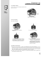
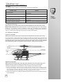
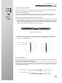
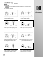
1
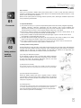
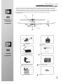
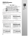
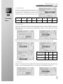
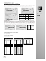
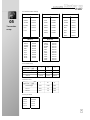
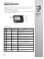
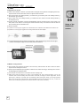
Specifications:
Main Rotor Dia. : 462mm
Standard transmitter: DEVO-7E
Tail Motor: 1627F
Tail Rotor Dia. : 113mm
Optional transmitter: DEVO-6/7/8S/10/12S
Main Motor: 380PF
Overall Length: 440mm
Receiver: RX2637H-D
Recommend Environment: Indoor and Outdoor
All-up Weight: 420g (Battery included)
Gyro: 6-Axis
Recommend Experience Level: Intermediate Level
Battery: 11.1V 1000mAh Li-Po
Brush ESC: Master CP ESC
Product type: 200 size Collective Pitch Enter level helicopter
Servo: WK-7.6-6 / weight 8.5g / speed 0.09sec/60°(4.8V) / torque 0.9kg/cm (4.8V) / dimension 22.5×11.8×24mm
Features:
1) Latest 6-Axis stability enhance Control system ensures stable and precise flight , it is easy to control for both basic
flight and 3D flight, 100% decrease the difficulty of the operation.
2) High performance Brushed motor not only reduce the cost,but also ensures enough powerful to do 3D as the brushless motor.
3) Adopts 2.4 GHz technology and supports both fixed and automatic ID binding and ID assignment.
4) The RX firmware can Update Online (required UP02 upgrade cable and adapter ).
5) Telemetry function can be accomplished after update the RX firmware. The Telemetry helps you get a real time data
feedback about the Battery Voltage and the Motor Temperature .(A telemetry function Radio is a must)
Contents
01. Forewords
1
08. Servo setup and adjustment
12
02. Safety matters needing attention
1
8.1 Specification and function of servo
12
2.1 Important Statement
1
2.2 Safety matters needing attention
1
8.1.1 Specification of servo
12
8.1.2 Basic function of servo
12
(1) Far away from obstacles and people
1
(2) Keep away from humidity
1
(3) Proper operation and maintenance
1
8.2.1 Connection of servos
12
(4) Avoid flying alone
1
8.2.2 Adjustment of servos
12
(5) Safe operation
2
8.2.3 Matters needing attention
12
(6) Keep away from high-speed rotating parts
2
(7) Protect from heat
2
8.2 Connection and adjustment of servos
09. Instruction and attention
of GA005 balance charger
2.3 Attention before flight
03. Definition of Helicopter Orientation
12
13
2
9.1 Parameters of GA005 balance charger
13
9.2 Features of GA005 balance charger
13
3
04. Standard equipments
3
9.3 Instruction of GA005 balance charger
13
05. Transmitter setup
4
9.4 Operation steps
13
5.1 DEVO-7E(standard radio) setting
4
9.5 Charging status corresponding to LED
14
5.2 DEVO-6/7/8S/10/12S(optional radio) settings
6
9.6 Matters needing attention
14
06. Setup of the RX2637H-D receiver
8
9.7 Maintenance of battery pack
14
6.1 RX2637H-D receiver features
8
10. Steps of flight
15
6.2 Function of receiver
8
10.1 Installation of battery
15
6.3 Channel connection of receiver
9
10.2 Turn on the power
15
6.4 Testing Mode setting
9
6.5 Adjustment of receiver
10
6.6 Matters needing attention
10
10.2.1 Turn on the power
15
10.2.2 Matters needing attention
15
10.2.3 Trouble shooting a flashing receiver
LED after connecting the power cable
16
07. Instruction and attention of ESC
11
7.1 Function of brush ESC
11
7.2 Connection method of brush ESC
11
10.3.1 Adjustment of swashplate
16
7.3 Matters needing attention
11
10.4 Adjustment of main rotor blades
17
10.3 Adjustment before flight
16
10.4.1 Color decal (tracking tape)
17
10.4.2 Inspection and gravity center
adjustment of main rotor blades
17
10.4.3 Tracking inspection
17
10.4.4 Adjustment of blade tracking
18
11. Flight over
18
Appendix 1-Flight control
19
Appendix 2 – Flight practice
20
1 Flight practice for the beginner
20
1.1Matters needing attention
20
1.2 Steps
20
2 Advanced practice
21
2.1 Frog-hopping practice
21
2.2 Controlled take off and landing practice
21
2.3 Square flight practice
21
2.4 Figure eight practice
21
2.5 Aerobatic flight
22
Dear customer:
Thank you for purchasing a Walkera radio control aircraft product. In order to quickly and safely master the
operation of the Master CP RC helicopter, please read the user handbook carefully and then keep it in a safe
place for future consultation and reference.
Master CP with spread spectrum technology features impressive power, stable flight, immediate response and
strong anti-jamming characteristics.
01
2.1 Important Statement
Forewords
(1) This product is not a toy. It is a piece of complicated equipment which harmoniously integrates engineering
materials, mechanics, electronics, aerodynamic and high frequency radio. Correct installation and
adjustment are necessary to avoid accidents taking place. The owner must always operate in a safe manner.
Improper operation may result in serious property damage, bodily injury or even death.
(2) We accept no liability for damage and consequent damage arising from the use of these products, as we
have no control over the way they are maintained, used and operated.
(3) This product is suitable for experienced RC Helicopter pilots aged 14 years or more.All minors must be
accompanied by a responsible adult when flying.
(4) The flight field should be legally approved by the local government. We accept no liability for any safety
duties or fines arising from operation, usage or mis-control after the sale of the products .
(5) We consign our distributors to offer technical support and service after sale. Please contact the local distributors
for problem resolution caused by usage, operation, maintenance, etc.
2.2 Safety matters needing attention
02
Safety matters
needing
attention
RC helicopter flight is a high risk hobby, whose flight should be kept far away from other people. Mis-assembled
or broken main frame, defective electronic equipment, and/or problematic radio system will lead to unforeseen
accidents such as bodily injury or property damage. The pilot MUST pay attention to the flight safety and
UNDERSTAND his responsibility for accidents caused by his carelessness.
(1) Far away from obstacles and people
An RC helicopter in flight has risk of uncertain flight speed and direction
which is potentially dangerous. When flying, please keep your RC helicopter
far away from people, high buildings, high-tension lines, etc, and avoid
operating in rain, storms, thunder and lightening.
(2) Keep away from humidity
RC helicopter should be kept away from humidity and vapor because its
complex,precise electronic components and mechanical parts may be damaged.
(3) Proper operation and maintenance
Please use Walkera original spare parts to upgrade, modify or maintain
your helicopter in order to ensure its safety. Please operate your helicopter
within the range of functions permitted. It is forbidden to use it outside of the
safety laws or regulations.
(4) Avoid flying alone
At the beginning of learning about radio-controlled flight there are some difficulties
to overcome. Please avoid flying alone. Invite experienced pilots to guide you
(two of the most effective methods to practice are via a PC flight simulator
and/or under the supervision of a skilled pilot).
1
(5) Safe operation
Please fly your helicopter according to your physical status and
flight skills. Fatigue, listlessness and mis-operation will increase the
possibilities of accidental hazard.
(6) Keep away from high-speed rotating parts
Please keep the spinning blades of both main rotor and tail rotor
away from the pilot, people and other objects.
(7) Protect from heat
An RC helicopter is made from metal, fiber, plastic and electronic
components, etc. Please keep away from heat and sunshine in order to
avoid distortion, even damage, caused by high temperatures.
2.3 Attention before flight
(1) Ensure the battery packs of both transmitter and receiver are fully charged (saturated).
(2) Ensure both the throttle stick and the throttle trim of your transmitter stay at the lowest positions before
operation.
(3) Please strictly obey the order of turn-on and turn-off before operation. When starting your flight, please turn
on your transmitter first, and connect the power cable of your helicopter last.
When finishing your flight, please disconnect the power cable of your helicopter first, and turn off your
transmitter last.
(4) An upset in the order of connection may cause your helicopter to loose control. Please cultivate a correct
habit of turn-on and turn-off.
(5) Ensure the directions and actions which servos execute transmitter commands are correct and smooth,
respectively. Using a broken servo will result in unforeseen dangers.
(6) Check there are no missing or loose screws and nuts, no unassembled or damaged parts. Carefully check the
main blades have no defects, especially the position close to the main blade connector. Broken or unassembled
parts will have an effect on the flight performance, and will cause unforeseen potential dangers.
(7) Check all the connections between ball linkage and ball. Loose linkages and balls should be changed.
Loose connection between linkage and ball will have an effect on the flight performance, even lose control.
(8) Assure there are solid connections between the power cables of battery pack and motors. Continuous
vibrations in flight may loosen the battery tie-ins.
2
02
Safety matters
needing
attention
In order to avoid confusion, the following sections will use the directions and orientations defined as follows.The
helicopter is in front of the pilot with the tail boom and rotor closest to the pilot (tail in), the head or nose is facing
forward (pointing away from the pilot).The left hand of the pilot is to the left side of the helicopter, the right hand of the
pilot is to the right side of the helicopter.Its head/nose is to the front and it's tail boom is to the back. The direction in
which the main body is facing is defined as up and its skids are in the down direction, as shown in
the diagram below.
up
right
03
Definition of
Helicopter
Orientation
front
back
left
down
Helicopter
Transmitter
04
Standard
Li-polymer battery pack
Tool kit
equipments
Wall adapter /Power supply
User Handbook
GA005 balance charger
PIT Gauge
3
5.1 DEVO-7E(standard radio) setting
5.1.1 Boost Screen
Elevator trim
Throttle trim
Transmission power display
Battery charge
indicator
Model name
Transmitter
Timer display
Model type
display
Throttle percentage
value
Rudder trim display
Aileron trim
display
5.1.2 Type Select
Press ENT to get Main Menu and press UP or DN to select Model Menu. Press ENT to enter and press UP or
DN to select Type Select and press ENT to enter setting interface.Press R or L to get the icon of Helicopter
and press ENT to confirm, then press EXT to exit.
5.1.3 Model Select
Press UP or DN to select Model select in Model Menu, press ENT to get the Model Select setting interface;
press UP or DN to select MOD 1, then press ENT to confirm and then press EXT to exit.
5.1.2 Type Select
5.1.3 Model Select
5.1.4 Model Name
Press UP or DN to select Model Name in Model Menu, press ENT to get the Model Name setting interface.
Press UP or DN to select the character and figure which are needed to be changed, press R or L to change
character and named "MASTERCP". press EXT to exit after finished.
5.1.5 Swash Type
Press UP or DN to choose SWASH in Model Menu, press ENT enter to Swash setting interface. press UP or
DN to choose 1 Servo Normal, and press ENT to confirm and then press EXT to exit.
5.1.4 Model Name 5.1.5 Swash Type 5.1.6 Device Output
Press UP or DN to select Output Device in Model Menu and press ENT to enter Output Device interface;press UP or
DN to select "HOLD SW" "Activate", and "FMOD SW" "Gyro". Press ENT to confirm and then press EXT to exit.
4
05
setup
5.1.7 Reverse Switch
05
Press UP or DN to select Function Menu in Mian Menu, press
UP or DN to choose Reverse Switch and press ENT to enter
into Reverse Switch interface;press UP or DN to choose
channel, press R or L to shift the status between normal and
reverse.and press ENT to confrim and then press EXT to exit.
Transmitter
Channel
setup
Status
Elevator
Aileron
Throttle
Rudder
Gear
Pitch
Gyro
Normal
Normal
Normal
Normal
Normal
Normal
Normal
5.1.8 Throttle Curve
Press UP or DN to select Throttle Curve in Function Menu, press ENT, the enquiry dropdown is shown "All
servos hold?" press R or L to choose Cancel, and press ENT to confirm. There are total two flight modes:
Normal Flight, Stunt, and the flight mode can be shifted by FMOD. Press DN , you can shoose On or Off, press
R/L to choose On.
Press DN, there will interface of Curve Point, choose L M H by press R/L. press DN, there will be Output
Setting. press R/L to choose the value of point, and press ENT to confirm and then press EXT to exit.
point
Flight mode
output
Normal Flight
Stunt
L
M
H
50.0%
100.0%
100.0% 75.0%
100.0%
0.0%
5.1.9 Pitch Curve
Press UP or DN to select Pitch Curve in Function Menu, press ENT, the enquiry dropdown is shown "All servos hold?"
press R or L to choose Cancel, and press ENT to confirm. There are total two flight modes: Normal Flight, Stunt, and
the flight mode can be shifted by FMOD. Press DN , you can shoose On or Off, press R/L to choose On.
5
Press DN, there will interface of Curve Point, choose L M H by press R/L. press DN, there will be Output
Setting. Press R/L to choose the value of point, and press ENT to confirm and then press EXT to exit.
05
Transmitter
point
Flight mode
output
L
M
H
Normal Flight
-15%
+25%
+55%
Stunt
-55%
+0%
+55%
5.1.10 Gyro Sensor
Press UP/DN to choose Gyro Sensor in Functional Menu, then press ENT into Gyro Sensor interface, press R
or L to choose Manual Setting; press DN, SWITCH will be shown, press R or L to choose HOLD SW; press
DN, "Pos 0" will be show first, and press R/L to increase/decrase value individually. Press DN "Pos 1" will be
show after finishing "Pos 0". and press ENT to confirm and then press EXT to exit.
Mode
Manual
Switch
HOLD SW
Pos 0
75.0%
Pos 1
50.0%
5.2 DEVO-6/7/8S/10/12S(optional radio) settings
5.2.1 Type:Helicopter
5.2.2 Swash type:1 Servo Normal
5.2.3 Device Output
DEVO-6
DEVO-7
Gear
GEAR SW
Gyro
GEAR
GEAR
ACT
Pitch
System
Active
AUX2
AUX2
GYRO
DEVO-10
DEVO-12S
Gear
GEAR SW
Active
AUX2
FMOD SW
Gyro
AUX3
RUDD D/R
Active
AUX4
AUX4 KB
Active
AUX5
AUX5 KB
Active
6
DEVO-8S
Gear
Pitch
GEAR SW
System
Active
Active
AUX2
AUX2 Lever Gyro
AUX3
AUX3 Lever Active
AUX4
AUX4 Lever Active
AUX5
AUX5 Lever Active
AUX6
AUX6 Knob
Active
AUX7
AUX7 Knob
Active
Gear
GEAR SW
Active
Pitch
System
Active
AUX2
FMOD SW
Gyro
AUX3
RUDD D/R
Active
setup
5.2.4 Reverse switch settings
DEVO-6
05
Transmitter
setup
DEVO-7
DEVO-8S
Elevator
Normal
ELEV
NORM
Elevator
Normal
Aileron
Normal
AILE
NORM
Aileron
Normal
Throttle
Normal
THRO
NORM
Throttle
Normal
Rudder
Normal
RUDD
NORM
Rudder
Normal
Gyro
Normal
GEAR
NORM
Gear
Normal
Pitch
Normal
PITCH
NORM
Pitch
Normal
GRYO
NORM
Gyro
Normal
AUX3
Normal
DEVO-10
DEVO-12S
Elevator
Normal
Aileron
Normal
Throttle
Normal
Rudder
Normal
Gear
Normal
Pitch
Normal
Gyro
Normal
AUX3
Normal
AUX4
Normal
AUX5
Normal
Elevator
Aileron
Throttle
Rudder
Gear
Pitch
Normal
Normal
Normal
Normal
Normal
Normal
Gyro
AUX3
Normal
Normal
AUX4
Normal
AUX5
AUX6
AUX7
Normal
Normal
Normal
5.2.5 Throttle curve
point
Flight mode
L
output
M
H
Normal Flight
0.0%
50.0%
100.0%
Stunt 1
100.0%
75.0%
100.0%
Stunt 2
100.0%
75.0%
100.0%
5.2.6 Pitch curve
point
L
M
H
Normal Flight
-15%
+25%
+55%
Stunt 1
-55%
0%
+55%
Stunt 2
-55%
0%
+55%
Flight mode
output
5.2.6 Gyro sensor
Mode
Manual
Switch
MIX SW
Pos 0
75.0%
Pos 1
70.0%
Pos 2
50.0%
7
6.1 RX2637H-D receiver features
(1) Adopts 2.4G DSSS technology with the functions of automatic scanning, code binding and LED receiving
indication.
(2) The use of a high performance receiver dramatically reduces the possibility of signal loss and ensures
the accuracy and reliability of signal reception.
(3) makes fine actions and powerful functions available.
(4) Controlled by 6-axis gyro,with flybarless balance electronic system, amend flight status automatically,
makes more stable flight and flexible 3D performance.
06
Setup of the
RX2637H-D
receiver
6.2 Functions of receiver
S/N
Name for short
Full name
Function
Connects to the elevator servo and receives the control
signal of elevator servo.
1
ELEV
Elevator servo
2
AILE
Aileron servo
Connects to the aileron servo and receives the control
signal of aileron servo.
3
PIT
Pitch servo
Connects to the PIT servo and receives the control signal
of PIT servo.
4
Not used
Not used
Not used
5
THRO
Throttle
Connects to the main motor signal wire of ESC, and
receive the control signal of main motor.
6
Not used
Not used
Not used
7
POWER CHECK Power check
Connects to Power check signal wire of ESC.
8
SPARE
Spare chanel
Spare chanel(After receiver upgrade to the programe with
telemetry function, it can connect to the temperature
sensor to monitor the motor temperature.
9
TAIL MOT
Tail motor
Connects to tail motor signal wire of ESC, receive control
signal of tail motor.
10
ELEV G.S
Elevator gyro
sensitivity adjust dial
Adjusts the Elevator gyro sensitivity gain, changes the
flight effect.
11
AILE G.S
Aileron gyro
sensitivity adjust dial
Adjusts the Aileron gyro sensitivity gain, changes the flight
effect.
12
ELEV/AILE EXT. extent dial
Elevator/Aileron servo
8
Adjusts Elevator/Aileron servo Travel.
6.3 Channel connection of receiver
AILE
06
ELEV
PIT
Setup of the
RX2637H-D
receiver
9
ELEV
The white wire is facing front.
AILE
The white wire is facing front.
PIT
The white wire is facing front.
Not used
Not used.
THRO
Connects to the main motor signal wire of ESC. The white wire is facing front.
Not used
Not used.
POWER CHECK
Connects to Power check signal wire of ESC.
SPARE
After receiver upgrade to the programe with
telemetry function, connect to the temperature
sensor.
TAIL MOT
Connects to tail motor signal wire of ESC.
The red wire is facing front.
The Orange wire is facing front.
6.4 Testing Mode setting
Note: When mounting the receiver, please make sure the receiver is placed flat and perpendicular to
the main axis of the helicopter main rotor.
(1) Standard Transmitter: DEVO-7E
After code pairing successfully, Switch HOLD to position 1 and make sure the gyro setting position 1 Value
*50.0%. Meanwhile the LED indicator starts to flash slowly, it enters into testing mode. You can adjust the
swashplate to horizontal level by adjusting the servos or mechanism or PIT adjustment. Switch HOLD to position
0 to enter flight mode after the adjustment finished. Flight is prohibited under testing mode.
HOLD SW
MIX SW
(2) DEVO-6/7/8S/10/12S Transmitter selectable
After code pairing successfully, Switch MIX to position 2 and make sure the gyro setting position 2 Value
*50.0%. Meanwhile the LED indicator starts to flash slowly, it enters into testing mode. You can adjust the
swashplate to horizontal level by adjusting the servos or mechanism or PIT adjustment. Switch MIX to position 0
to enter flight mode after the adjustment finished. Flight is prohibited under testing mode.
9
6.5 Adjustment of receiver
(1) Status of LED indicator of receiver: quick flash means the signal is being received; solid lighting means the
signal has been received; slow flash means no signal has been received.
(2) Gyro turning knob: CW rotating towards (+) increases the gyro sensitivity and CCW rotating towards (-)
decreases the gyro sensitivity.
(3) Servo extent knob: CW rotating towards (+) increases the servo travel and CCW rotating towards (-)
decreases the travel.
06
(4) Receiver fixed ID cancellation: Insert the supplied BIND PLUG into the ELEV channel in the receiver, and
then power on the receiver. The red light of receiver will flash slowly. This means the fixed ID code has
been cancelled. Remove the BIND PLUG.
Setup of the
(5) Receiver upgrade:
RX2637H-D
(5.1) Master CP control program upgrade can be downloaded online at Walkera Offical Website:www.walkera.com.
receiver
(5.2) Master CP control program upgrade tool including UP02 cable and UP02 Adapter.
UP02 Adapter
UP02
(5.3) Connect blue single wire plug to ELEV signal position, yellow single wire plug connect to AILE signal
position; black single wire plug connect to AILE position of earth wire.
Yellow single wire
Blue single wire
UP02 Adapter
UP02
Black single wire
6.6 Matters needing attention
(1) All the signal wires should be connected in the correct way. Misconnection will result in failure to receive
signal and even damage the receiver.
(2) Use the special adjustment pen supplied to rotate the servo extent dial and gyro sensitivity dial in order to
avoid damaging the adjustment dials.
(3) The helicopter must be placed in horizontal level when matching code.
(4) Please strictly follow the sequence of "power on the transmitter first, then connect the battery". Turn on the
transmitter, then connect the battery with receiver within 10 seconds, the red light on receiver begins flash. The red
light will get a solid light 1-3 seconds, after the transmitter finishes pairing with receiver, the red light will flash
again. If the red light get a solid light and a mechanical BEEP sound can be heard from the servo, it means the
receiver have received the signal from the transmitter and their codes match successfully.
10
7.1 Function of brush ESC
07
Instructio
n
and
attention
of ESC
Electronic Speed Controller (ESC), mainly used in EP helicopter as a drive output device, is an electronic
control circuit for the revolution speed and CW- and CCW-rotation of the motor. It will magnify the proportional
signal it receives into voltage and current that can be directly exploited by the motor, the advantages of which,
compared with the traditional mechanical speed controller, include compact dimension, long longevity, high
efficiency and high output power.
7.2 Connection method of brush ESC
*
*
*
*
*
*
S/N
Full name
Function
1
Tail motor connecting wire
connect with Tail motor.
2
Main motor connecting wire
Connect with Main motor.
3
Power connecting wire
Connect with Lipo battery.
4
Tail motor signal wire
Connect with TAIL MOT channel of receiver.
5
Main motor signal wire
Connect with THRO channel of receiver.
6
Low voltage protection signal wire
Connect with POWER CHECK channel of receiver.
7.3 Matters needing attention
All the signal plugs of brushless ESC wires should be correctly connected, Otherwise the brushless ESC may
fail to operate correctly.
11
8.1 Specification and function of
servo 8.1.1 Specification of servo
Weight
wk-7.6-6
Voltage
8.5 g
4.8~6V
Torque
Speed
Dimension
0.9kgf.cm
0.09sec/60*
22.5*11.8*24mm
8.1.2 Basic function of servo
A servo is an electro-mechanical device that converts a signal from the receiver into mechanical movement.
By means of a sensor the accurate control of its direction and speed is possible.
8.2 Connection and adjustment of servos
8.2.1 Connection of servos
AILE
ELEV
PIT
S/N
Receiver
terminal
Connection method
Wire direction
1
ELEV
Connects to the plug of elevator servo signal wire
The white wire is facing front
2
AILE
Connects to the plug of aileron servo signal wire
The white wire is facing front
3
PIT
connects to the plug of pitch servo signal wire
The white wire is facing front
8.2.2 Adjustment of servos
Before departure from the factory, all the servos have been correctly adjusted and are locked in the correct
position. In general no adjustment is needed.
8.2.3 Matters needing attention
(1) All the plugs should be correctly connected. An incorrect connection will cause the servos not to function or
to operate in a direction which is different from the one required.
(2) Please ensure that the travel extents of the servo bell cranks are all within the permitted maximum range
after maintenance, replacement or adjustment of servo linkages. Failure to do this could cause a servo to
jam at maximum travel causing loss of control, damage and possibly injury.
12
08
Servo setup
and
adjustment
9.1 Parameters of GA005 balance charger:
Input voltage
09
Instruction
and
attention
of GA005
balance
charger
DC15-18V
Input current
1000mA
Output current
*800mA
Dimension
62.5*47*20.8mm
Weight
46g
9.2 Features of GA005 balance charger
(1) GA005 utilizes microcomputer chips to monitor and control over the whole charging process in a balanced
way with LED indicating light to display the charging status at real time.
(2) Connects to an input power supply (DC 15-18V 1000 mA).
(3) GA005 is suitable for 2-3S (7.4V/ 11.1V) Li-ion or Li-polymer battery pack.
(4) Automatically detects 2-3S Lithium battery. GA005 will automatically charge when it finds the voltage of
anyone cell among the LiPo pack is excessively low. At the same time LED displays as charging status
(flash in red). The voltage of anyone cell LiPo is controlled at the level of 4.2 ± 0.05V to ensure the
maximum voltage difference of single cell in the battery is less than 50 mV.
9.3 Instruction of GA005 balance charger
Status LED
Polarity Assignment
Diagram
12.6V 8.4V 4.2V 0V
Charging jack for
7.4V battery
Charging jack for
11.1V battery
Input jack
9.4 Operation steps
Plug the wall adapter into the mains
power supply. Its output end connects
to GA005. Then its LED is lighting in
solid red.
Insert the balanced pin of LiPo
battery into GA005.
During charging, Red LED is
continuously flashing. If saturated,
Red LED becomes solid green
lighting.
13
9.5 Charging status corresponding to LED
steps
Operation
1
Insert the wall adapter into the mains
power supply, and then its output is
connecting to GA005.
2
Step 1 + connect the battery to GA005
LED Status
Charging status
LED is in red solid lighting
Power on
LED is flashing in red
Charging
LED becomes from red to
solid green.
Saturated
09
Instruction
and
attention
9.6 Matters needing attention
(1) During charging, GA005 should be put in dry and ventilated place and be far away from heat sources and
inflammable and explosive substances.
(2) GA005 is only used to charging a 2S or 3S Li-ion or Li-polymer battery. It is forbidden to simultaneously
charge two or more sets of batteries packs. Either the charger or battery may be damaged.
(3) When charging, the battery should be removed from your helicopter. Never leave the charger unsupervised
during the process of charging in order to avoid risk of accidents.
(4) Never immediately charge your battery as soon as the flight is finished, or when its temperature doesn’t
cool down. Otherwise the battery will take a risk in swelling, even catch a fire.
(5) Ensure the correctness of polarity before connecting the battery to charger.
(6) Avoid drop and violence during the process of charging. Drop and violence will result in internal short circuit
of the battery.
(7) For the sake of safety, please use original charging equipment (wall adapter + GA005 balance charger)
and battery pack. Please change new one in time when the old battery is becoming swollen due to long
time usage.
(8) If it is retained in the charger for a long time after saturated, the battery may automatically discharge. When
the charger detects that the voltage of individual cells is lower than the rated voltage, it will re-charge until
saturated. Frequently charging and discharging will shorten the lifetime of your battery.
9.7 Maintenance of battery pack
(1) The battery should be put in dry and ventilated place. The storage temperature of the environment is ranged
from 18C* to 25C*.
(2) Please avoid frequent charging and excessive discharging the battery in order to prolong its life cycle.
(3) It is a must to maintain the battery before long-term storage. That is to charge the battery to the level of 5060% saturation.
(4) If the storage term is over 1 month, it is advised to monthly check the voltage of every cell of the battery
pack. The voltage of every cell should be not less than 3V. Otherwise, please refer to the above article (3).
(5) From the view point of protection, new battery should be motivated before usage. That is to charge and
discharge 3-5 times, but discharge is not less than the level of 70% saturation. This process will make the
battery lifetime longer and voltage more stable.
14
of GA005
balance
charger
10.1 Installation of battery
Install the battery pack into the battery compartment in the
direction of the arrow.
10
Steps
of flight
Battery
location
Diagram of battery installation.
10.2 Turn on the power
10.2.1 Turn on the power
1. Install the battery pack in the battery
compartment.
3. Pull down the throttle stick and throttle trim
of transmitter to the lowest position, and then
move the elevator trim, aileron trim, and rudder
trim at the neutral positions, respectively.
2. Turn on the power of transmitter.
4. Connect the power cable of the helicopter
and wait to receive the signal from the
transmitter. The helicopter should be
placed on flat ground or surface during
code paring (binding). Do not move the
transmitter sticks or the helicopter until
binding has completed.
10.2.2 Matters needing attention
(1) Please strictly follow the sequence of "power on the transmitter first, then connect the battery". Turn on the
transmitter, then connect the battery with receiver within 10 seconds, the red light on receiver begins flash. The red
light will get a solid light 1-3 seconds, after the transmitter finishes pairing with receiver, the red light will flash
again. If the red light get a solid light and a mechanical BEEP sound can be heard from the servo, it means the
receiver have received the signal from the transmitter and their codes match successfully.
(2) If failed to connect the power cable of helicopter in 10 seconds after transmitter is turned on, please turn off
the transmitter and repeat the step (1).
15
10.2.3 Trouble shooting a flashing receiver LED after connecting the power cable
Possible causes
Solutions
The throttle trim and throttle stick of transmitter
are not at the lowest position.
Turn transmitter off then on and re-connect helicopter
power cable.
Pull down the throttle trim and throttle stick to the
lowest position and re-code pair.
The transmitter battery is low or empty.
Replace transmitter battery and re-code pair (re-bind).
The helicopter battery is low or empty.
Replace the helicopter battery with a fresh pack and
re-code pair.
No function in receiver or transmitter.
Replace faulty receiver or transmitter and re-code pair.
Code pairing failed.
10.3 Adjustment before flight
Warning: Disconnect the power cable of main motor before adjustment for the sake of pilot’s safety.
Matters needing attention: Before departing the factory, all of the components have been correctly adjusted.
Normally it is not necessary to make any adjustment. However, due to disturbance during long-distance
transportation, some joints, screws or parts may be loose or even damaged. For safety's sake, please refer to
section 2.3 - "attention before flight" and strictly follow the helicopter checks described.
10.3.1 Adjustment of swashplate
Inspection of swashplate
Warning: Disconnect the power cable of main motor before adjustment for the sake of pilot’s safety.
Put your helicopter in a spacious horizontal ground. Move the throttle stick and throttle trim of transmitter to the
lowest position, and move the elevator , aileron and rudder trim at the neutral position, respectively. Turn on the
transmitter first and then connect the power cable of helicopter. After the LED indicator of receiver keeps solid
while mechanic beeps of servos initiation heard, the signal has been received. Then check whether the bottom
level of swashplate is parallel to the longitudinal axis of the helicopter – the extension line of tail boom.
Ball linkages of
swashplate
Swashplate
Bottom level
of swashplate
Parallel
Extension line
of tail boom
Adjustment of swashplate
Warning: Disconnect the power cable of main motor before adjustment for the sake of pilot’s safety. Servo
bellcranks must be horizontal at mid throttle. Swashplate must be at centrer of travel at mid throttle
If the bottom of swashplate is not in horizontal level, it can be adjusted via the following two steps:
(1) Adjust the bellcrank of servo. Disconnect the power cable of helicopter first and then turn off transmitter. Unscrew
the screw in the bellcrank of servo and take off the bellcrank. Re-turn on transmitter and re-connect the power
cable of helicopter in sequence. After servos’ initialization, re-mount the bellcrank of servo and make sure the
angle is 90 between bellcrank and ball linkage of servo, and then tighten the screw of bellcrank.
(2) Adjust the ball linkage of servo. Make the swashplate parallel to the horizontal level via adjusting the length
of servo ball linkage.
16
10
Steps
of flight
10.4 Adjustment of main rotor blades
The purpose of adjustment is to make the weight and gravity center of main rotor blades equally distributing and
ensure the main rotor blades are in same level during high speed spinning.
10.4.1 Color decal (tracking tape)
10
Steps
of flight
Two different colored blade tracking decales should be placed 20mm away from each end of blade tip,whose
purpose is to identify the position of each spinning blade in the following inspection of the blade tracking.
10.4.2 Inspection and gravity center adjustment of main rotor blades
(1) Transverse inspection and adjustment of gravity center. Use a bolt to insert the mounting hole of main rotor
blades and screw the bolt cap, and then stretch the main rotor blades in line. Hang the couple of main rotor
blades in the air using the bolt as a fulcrum. If the main rotor blades keep in a horizontal line, it means ok; if
one end of the main rotor blades is higher than the other one, please move the high end stick to the high
direction, and/ or move the low end stick to the high end until balanced.
Mounting hole of main rotor blades
(2) Longitudinal inspection of gravity center. Shown as below, take the mounting hole of main rotor blades as
the fulcrum to vertically hang in the air. If the main rotor blades are almost superposed, it means normal
(shown as Fig. A); otherwise abnormal.
Mounting hole of main
rotor blades
A
B
10.4.3 Tracking inspection
Note: for the sake of safety, please keep the main rotor blades of helicopter at least 3 meters away from
the pilot when his inspecting the tracking problem.
Slowly push up the throttle stick of the transmitter and ensure both the line of sight of the pilot and the main
rotor baldes are in the same horizontal level.when the main rotor blades are spinning,please observe whether
or not the levels are superposed in the same level.superposition is correct , otherwise there exists tracking
problem and adjustment is required
Correct blade tracking
Incorrect blade tracking
17
10.4.4 Adjustment of blade tracking
Below are the main course for incorrect balde tracking *
(1) The weights of blades are unequal.
Short ball
linkages of
main baldes
(2) The gravity center distribution of blades is unequal.
10
(3) The lengths of ball linkages of two blades are set improperly.
(4) When blades are too loose, blades shake due to gap,
or main blade connectors distort.
Steps
of flight
When there exists tracking baldes, please shorten the
length of the ball ge of the linkage located In the of the
higher blade, or prolong the length of the ball ball linkage
located in the of the lower blade
If the main blades are normal at low speed but abnormal at high speed, or normal at high speed but abnormal
at low speed, please check whether or not the main blade connectors are loose or distorted. If the main blade
connectors are loose, please tighten their screws; if the main blade connectors distort, please change new
one. The bad blade tracking can be removed just by repeatedly fine adjustments.
11
Flight over
Step 1: disconnect the power
cable of helicopter.
18
Step 2: turn off the
transmitter.
Step 3: Remove the battery pack.
Mode 1 (throttle stick at right hand)
Appendix 1Flight control
1. When moving the aileron stick left or right, the
helicopter accordingly flies left or right.
2. When moving the throttle stick up or down,
the helicopter accordingly flies up or down.
3. When moving the rudder stick left or right, the
head of helicopter accordingly rotates to the
left or right.
4. When moving the elevator stick up or down, the
helicopter accordingly flies forward or backward.
Mode 2 (throttle stick at left hand)
1. When moving the aileron stick left or right, the
helicopter accordingly flies left or right.
2. When moving the throttle stick up or down, the
helicopter accordingly flies up or down.
3. When moving the rudder stick left or right, the
head of helicopter accordingly rotates to the
left or right.
4. When moving elevator stick up or down, the
helicopter according flies forward or backward.
19
1 Flight practice for the beginner
1.1Matters needing attention
(1) The beginners should be supervised and guided by skilled pilots when practicing.
(2) For the sake of safety, people should keep at least 5 meters away from the helicopter during practicing.
(3) Choose a spacious ground without people and obstacles as the flight practice field.
(4) This is a 3D helicopter. We kindly suggest that the knowledge of flying 2D/ coaxial helicopter is preliminary
before flight.
1.2 Steps
(1) Practice of throttle control - stationary flight
When helicopter taking off from the ground, slowly pull down the throttle stick and land it on gradually and
stably. Repeatedly practice this step until controlling over the throttle stick with facility.
When hovering, tail rotor counteracts torque but also pushes helicopter to the left. Don’t forget to counteract
this effect using cyclic stick to the right and take off slightly inclined. It is important to hover vertically, stabilize
helicopter at 1.5m height and then land it.
Mode 1
Mode 2
(2) Practice of aileron and elevator control
Mode 1
Mode 2
Slowly push up the throttle stick to purposely fly your helicopter forward, backward, left and right; then
reversely control over the aileron stick and elevator stick to fly your helicopter back to the takeoff point.
Repeatedly practice this step until controlling with facility.
(3) Practice of rudder control
Mode 1
Mode 2
Slowly move the throttle stick to change the head of your helicopter left and right, respectively; reversely control
over the relative sticks to restore your helicopter. Repeatedly practice this step until controlling with facility.
(4) Practicing circular flight
After mastering steps (1) to (3) with ease, please draw or mark a large circle on the ground. Fly your helicopter
along this circular track until the flight is smooth and controlled.
You may wish to stand inside the circle at first to practice circular flight before needing to control the nose
in orientation.Fly circles in both directions and at a constant altitude to be comfortable with this step.
20
Appendix 2 –
Flight practice
2 Advanced practice
2.1 Frog-hopping practice
Repeat the take off and landing action using the throttle stick whilst maintaining a vertical path. Increase your
rate of ascent and descent gradually as you become more comfortable with the exercise. Be sure to slow
down in time when landing!
Appendix 2 –
Flight practice
2.2 Controlled take off and landing practice
Mark out an area on the ground as a landing pad to help practice deliberately taking off and landing from a
set location. The process of take off and landing should be kept stable and as close to vertical as possible.
2.3 Square flight practice
Take the takeoff point as the center to draw a square whose side length is about 2 meters. Fly your helicopter
along the 4 sides and keep the flight height parallel to the line of sight. Make a 90 degree rotation at each
corner of the quadrangle to adjust the flight direction. Train your straight flight skills and 90 degree flight course
control. Fly in both directions around the circuit until familiar with the maneuver.
2.4 Figure eight practice
Once you have mastered the previous steps you can try flying smooth flat figure eights. Try to maintain the
same altitude during the entire flight path. Take care when flying where there is wind as it may cause the
helicopter to suddenly rise or fall unexpectedly.
21
2.5 Aerobatic flight
Your Master CP can perform breathtaking and exciting aerobatic flight such as dives and inverted 3D.
Inverted flight
Mode 1 (throttle stick at right hand)
Appendix 2 –
Flight practice
1. When moving the aileron stick left or right,
simultaneously your helicopter flies left or right,
respectively.Orientation is normal.
3. When moving the rudder stick left or right, your
helicopter simultaneously flies right or left,
respectively.Orientation is inverted.
2. When moving the throttle stick up or down,
simultaneously your helicopter flies down or up
respectively.Orientation is inverted.
4. When moving the elevator stick up or down,
your helicopter simultaneously flies backward
or forward, respectively.Orientation is inverted.
Mode 2 (throttle stick at left hand)
1. When moving the aileron stick left or right, your
helicopter simultaneously flies left or right,
respectively.Orientation is normal.
2. When moving the throttle stick up or down, your
helicopter simultaneously flies down or up,
respectively.Orientation is inverted.
3. When moving the rudder stick left or right, the
head of your helicopter simultaneously flies right
or left, respectively.Orientation is inverted.
4. When moving elevator stick up or down, your
helicopter simultaneously flies backward or
22
forward, respectively.Orientation is inverted.