1
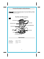
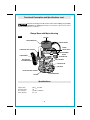
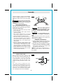
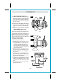
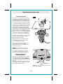
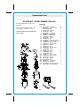
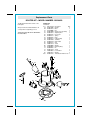
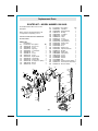
Operator’s Manual
®
P R O F E S S I O N A L
Fixed Base/Plunge Base
Router Kit
Model No.
130.26620
0
1 .5
MM
50
IN
2
40
30
1
20
10
0
CAUTION: Read, understand and follow
all Safety Rules and Operating Instructions
in this manual before using this product.
0
• SAFETY
• OPERATION
• MAINTENANCE
• ESPAÑOL
Sears, Roebuck and Co., Hoffman Estates, IL 60179 U.S.A.
Table of Contents
Warranty......................................................................................................Page 2
Safety Instructions...............………….........................................................Pages 3 - 5
Safety Symbols..............…………...............................................................Page 6
Functional Description and Specifications..................................................Pages 7 - 8
Assembly.....................................................................................................Pages 9 - 11
Operating Instructions………......................................................................Pages 12 - 19
Maintenance................................................................................................Page 20
Accessories.................................................................................................Page 20
Repair Parts.................................................................................................Pages 21 - 23
Service Numbers.........................................................................................Back Cover
Warranty
ONE FULL YEAR WARRANTY ON CRAFTSMAN PROFESSIONAL TOOL
If this Craftsman Tool fails to give complete satisfaction within one year from the date of
purchase, RETURN IT TO THE NEAREST SEARS STORE OR SEARS PARTS & REPAIR
CENTER IN THE UNITED STATES, and Sears will repair it, free of charge.
This warranty gives you specific legal rights, and you may also have other rights
which vary from state to state.
Sears, Roebuck and Co. Dept. 817 WA, Hoffman Estates, IL 60179
SAVE THESE INSTRUCTIONS!
READ ALL INSTRUCTIONS!
-2-
Power Tool Safety Rules
Read and understand all instructions. Failure to follow all instructions listed
! WARNING
below, may result in electric shock, fire and/or serious personal injury.
Work Area
SAVE THESE INSTRUCTIONS
reduce the risk of electric shock. Refer to
“Recommended sizes of Extension Cords” in
the Accessory section of this manual.
Keep your work area clean and well lit.
Cluttered benches and dark areas invite
accidents.
Do not operate power tools in explosive
atmospheres, such as in the presence of
flammable liquids, gases, or dust. Power
tools create sparks which may ignite the dust
or fumes.
Keep by-standers, children, and visitors
away while operating a power tool.
Distractions can cause you to lose control.
Electrical Safety
Double Insulated tools are equipped with a
polarized plug (one blade is wider than the
other.) This plug will fit in a polarized outlet
only one way. If the plug does not fit fully in
the outlet, reverse the plug. If it still does not
fit, contact a qualified electrician to install a
polarized outlet. Do not change the plug in
any way. Double Insulation xxxxeliminates the
need for the three wire grounded power
cord and grounded power supply system.
Before plugging in the tool, be certain the
outlet voltage supplied is within the voltage
marked on the nameplate. Do not use “AC
only” rated tools with a DC power supply.
Avoid body contact with grounded surfaces
such as pipes, radiators, ranges and
refrigerators. There is an increased risk of
electric shock if your body is grounded. If
operating the power tool in damp locations is
unavoidable, a Ground Fault Circuit Interrupter
must be used to supply the power to your tool.
Electrician’s rubber gloves and footwear will
further enhance your personal safety.
Don't expose power tools to rain or wet
conditions. Water entering a power tool will
increase the risk of electric shock.
Do not abuse the cord. Never use the cord
to carry the tools or pull the plug from an
outlet. Keep cord away from heat, oil, sharp
edges or moving parts. Replace damaged
cords immediately. Damaged cords increase
the risk of electric shock.
When operating a power tool outside, use an
outdoor extension cord marked "W-A" or
"W." These cords are rated for outdoor use and
-3-
Personal Safety
Stay alert, watch what you are doing and
use common sense when operating a power
tool. Do not use tool while tired or under the
influence of drugs, alcohol, or medication.
moment of inattention while operating power
tools may result in serious personal injury.
Dress properly. Do not wear loose clothing
or jewelry. Contain long hair. Keep your hair,
clothing, and gloves away from moving
parts. Loose clothes, jewelry, or long hair can
be caught in moving parts. Keep handles dry,
clean and free from oil and grease.
Avoid accidental starting. Be sure switch is
“OFF” before plugging in. Carrying tools with
your finger on the switch or plugging in tools
that have the switch “ON” invites accidents.
Remove adjusting keys or wrenches before
turning the tool “ON”. A wrench or a key that
is left attached to a rotating part of the tool may
result in personal injury.Do not overreach.
Keep proper footing and balance at all
times. Proper footing and balance enables
better control of the tool in unexpected
situations.
Use safety equipment. Always wear eye
protection. Dust mask, non-skid safety
shoes, hard hat, or hearing protection must be
used for appropriate conditions.
Tool Use and Care
Use clamps or other practical way to secure
and support the workpiece to a stable
platform. Holding the work by hand or against
your body is unstable and may lead to loss of
control.
Do not force tool. Use the correct tool for
your application. The correct tool will do the
job better and safer at the rate for which it is
designed.
Do not use tool if switch does not turn it
“ON” or “OFF”. Any tool that cannot be
controlled with the switch is dangerous and
must be repaired.
Power Tool Safety Rules cont.
Disconnect the plug from the power source
before making any adjustments, changing
accessories, or storing the tool. Such
preventive safety measures reduce the risk of
starting the tool accidentally.
Store idle tools out of reach of children and
other untrained persons. Tools are dangerous
in the hands of untrained users.
Maintain tools with care. Keep cutting tools
sharp and clean. Properly maintained tools,
with sharp cutting edges are less likely to bind
and are easier to control. Any alteration or
modification is a misuse and may result in a
dangerous condition.
Check for misalignment or binding of
moving parts, breakage of parts, and any
other condition that may affect the tool's
operation. If damaged, have the tool
serviced before using. Many accidents are
caused by poorly maintained tools. Develop a
periodic maintenance schedule for your tool.
Use only accessories that are sold at Sears
for your model. Accessories that may be
suitable for one tool, may become hazardous
when used on another tool.
Service
Tool service must be performed only by
qualified repair personnel. Service or
maintenance performed by unqualified
personnel could result in a risk of injury. For
example: internal wires may be misplaced or
pinched, safety guard return springs may be
improperly mounted.
When servicing a tool, use only identical
replacement parts. Follow instructions in the
Maintenance section of this manual.
unauthorized parts or failure to follow
Maintenance Instructions may create a risk of
electric shock or injury. Certain cleaning agents
such as gasoline, carbon tetrachloride,
ammonia, etc. may damage plastic parts.
Safety Rules for Routers
Hold tool by insulated gripping surfaces
when performing an operation where the
cutting tool may contact hidden wiring or its
own cord. Contact with a "live" wire will make
exposed metal parts of the tool "live" and
shock the operator. If cutting into existing walls
or other blind areas where electrical wiring may
exist is unavoidable, disconnect all fuses or
circuit breakers feeding this worksite.
Always make sure the work surface is free
from nails and other foreign objects. Cutting
into a nail can cause the bit and the tool to
jump and damage the bit.
Never hold the workpiece in one hand and
the tool in the other hand when in use.
Never place hands near or below cutting
surface. Clamping the material and guiding the
tool with both hands is safer.
Never lay workpiece on top of hard
surfaces, like concrete, stone, etc...
Protruding cutting bit may cause tool to jump.
Always wear safety goggles and dust mask.
Use only in well ventilated area. Using
personal safety devices and working in safe
environment reduces risk of injury.
-4-
After changing the bits or making any
adjustments, make sure the collet nut and
any other adjustment devices are securely
tightened. Loose adjustment device can
unexpectedly shift, causing loss of control,
loose rotating components will be violently
thrown.
Never start the tool when the bit is engaged
in the material. The bit cutting edge may grab
the material causing loss of control of the
cutter.
Always hold the tool with two hands during
start-up. The reaction torque of the motor can
cause the tool to twist.
The direction of feeding the bit into the
material is very important and it relates to
the direction of bit rotation. When viewing
the tool from the top, the bit rotates
clockwise. Feed direction of cutting must be
counter-clockwise. NOTE: inside and outside
cuts will require different feed direction, refer to
section on feeding the router. Feeding the tool
in the wrong direction, causes the cutting edge
of the bit to climb out of the work and pull the
tool in the direction of this feed.
Safety Rules for Routers cont.
Never use dull or damaged bits. Sharp bits
must be handled with care. Damaged bits can
snap during use. Dull bits require more force to
push the tool, possibly causing the bit to break.
Never touch the bit during or immediately
after the use. After use the bit is too hot to be
touched by bare hands.
Never lay the tool down until the motor has
come to a complete standstill. The spinning
bit can grab the surface and pull the tool out of
your control.
Never use bits that have a cutting diameter
greater than the opening in the base.
-5-
Some dust created by power
! WARNING sanding, sawing, grinding,
drilling, and other construction activities
contains chemicals known to cause cancer,
birth defects or other reproductive harm.
Some examples of these chemicals are:
• Lead from lead-based paints,
• Crystalline silica from bricks and cement and
other masonry products, and
• Arsenic and chromium from chemicallytreated lumber.
Your risk from these exposures varies,
depending on how often you do this type of
work. To reduce your exposure to these
chemicals: work in a well ventilated area, and
work with approved safety equipment, such as
those dust masks that are specially designed to
filter out microscopic particles.
Symbols
IMPORTANT: Some of the following symbols may be used on your tool. Please study them
and learn their meaning. Proper interpretation of these symbols will allow you to operate the
tool better and safer.
Symbol
Name
Designation/Explanation
V
Volts
Voltage (potential)
A
Amperes
Current
Hz
Hertz
Frequency (cycles per second)
W
Watt
Power
kg
Kilograms
Weight
min
Minutes
Time
s
Seconds
Time
Diameter
Size of drill bits, grinding wheels, etc.
No load speed
Rotational speed, at no load
n0
.../min
0
1, 2, 3, ...
I, II, III,
0
Revolutions or reciprocation per minute Revolutions, strokes, surface speed,
orbits etc. per minute
Off position
Zero speed, zero torque...
Selector settings
Speed, torque or position settings.
Higher number means greater speed
Infinitely variable selector with off
Speed is increasing from 0 setting
Arrow
Action in the direction of arrow
Alternating current
Type or a characteristic of current
Direct current
Type or a characteristic of current
Alternating or direct current
Type or a characteristic of current
Class II construction
Designates Double Insulated
Construction tools.
Earthing terminal
Grounding terminal
Warning symbol
Alerts user to warning messages
Ni-Cad RBRC seal
Designates Ni-Cad battery recycling
program
This symbol designates
that this tool is listed to
Canadian Standards by
Underwriters Laboratories.
This symbol designates
that this tool is listed by
Underwriters Laboratories.
This symbol
designates
that
this tool
complies
to NOM
Mexican
Standards.
This symbol designates
that this tool is listed by
the Canadian Standards
Association.
-6-
Functional Description and Specifications
Disconnect the plug from the power source before making any assembly,
! WARNING adjustments or changing accessories . Such preventive safety measures reduce
the risk of starting the tool accidentally.
Fixed Base with Motor Housing
FIG. 1
AIR VENTS
SPEED CONTROL DIAL
MOTOR HOUSING
ROCKER ON\OFF SWITCH
MOTOR ALIGNMENT ARROW
BASE CLAMP LEVER
ROUND
HANDLE
CHIP DEFLECTOR
SUB -BASE
BIT ROTATION ARROW
Specifications
Voltage rating
Amperage rating
No load speed
Collet capacities
120V
50 - 60Hz
12A
n0 8,000 - 25,000/min
1/4", 1/2"
-7-
Functional Description and Specifications cont.
Disconnect the plug from the power source before making any assembly,
adjustments or changing accessories. Such preventive safety measures reduce
the risk of starting the tool accidentally.
! WARNING
Plunge Base with Motor Housing
FIG. 2
AIR VENTS
SPEED CONTROL DIAL
MOTOR HOUSING
ROCKER
ON \OFF SWITCH
PLUNGE LOCK LEVER
MM
50
IN
2
MOTOR ALIGNMENT
ARROW
40
30
1
20
PLUNGE HANDLE
10
0
DEPTH INDICATOR
0
DEPTH ROD FINE
ADJUSTMENT KNOB
DEPTH ROD KNOB
CHIP DEFLECTOR
DEPTH ROD
DEPTH STOP TURRET
BIT ROTATION ARROW
SUB-BASE
Specifications
Voltage rating
Amperage rating
No load speed
Collet capacities
120V
50 - 60Hz
12A
n0 8,000 - 25,000/min
1/4", 1/2"
-8-
Assembly
A wide assortment of router bits with different
profiles is available separately. Use 1/2" shank
whenever possible, and only use good quality
bits.
FIG. 3
To prevent personal injury,
always remove the plug
from power source before removing or
installing bits or accessories.
! WARNING
INSTALLING A ROUTER BIT
Place router upside down or lay router on its
side with the base resting on the bench.
Another option is to remove the motor from the
base before installing the bit.
SHAFT
WRENCH
COLLET
WRENCH
When the template guide has
! WARNING been removed from base, do
1. Remove the chip shield (or flip up if plunge
base is attached).
2. Hold the armature shaft in place with the
shaft wrench (Fig. 3)
3. Next, use the collet wrench to loosen the
collet chuck assembly in counter-clockwise
direction (viewed from under the router).
4. Insert the shank of the router bit into the
collet chuck assembly as far as it will go,
then back the shank out until the cutters are
approximately 1/8" to 1/4" away from the
collet nut face.
5. With the router bit inserted and the shaft
wrench holding the armature shaft, use the
collet wrench to firmly tighten the collet
chuck assembly in a clockwise direction
(viewed from under the router). To ensure
proper gripping of the router bit and
minimize run-out, the shank of the router bit
must be inserted at least 5/8".
not use router bits greater than 1 5/8"
in diameter as they will not fit through
the sub-base.
! CAUTION
a bit.
To prevent damage to tool,
do not tighten collet without
NOTE: The bit shank and chuck should be
clean and free of dust, wood, residue and
grease before assembling.
REMOVING THE ROUTER BIT
1. Use the shaft and collet chuck wrenches as
described earlier, and turn the collet chuck
assembly in a counter-clockwise direction.
2. Once the collet chuck assembly is loosened
continue to turn the collet chuck assembly
until it pulls the collet free from its taper, and
the router bit can be removed.
NOTE: The collet chuck is self-extracting; it is
NOT necessary to strike the collet chuck to free
the router bit.
COLLET CHUCK CARE
With the router bit removed, continue to turn
the collet chuck counter-clockwise until it is
free of the shaft. To assure a firm grip,
occasionally blow out the collet chuck with
compressed air, and clean the taper in the
armature assembly shaft with a tissue or fine
brush.
FIG. 4
COLLET
COLLET
NUT
The collet chuck is made up of two
component parts as illustrated (Fig. 4); check to
see that the collet is properly seated in the
collet chuck nut and lightly thread the collet
chuck back onto the armature shaft. Replace
worn or damaged collet chucks immediately.
-9-
COLLET
CHUCK
Assembly cont.
REMOVING MOTOR FROM BASE
To remove motor from fixed base: (Fig. 5)
1. Hold router in horizontal position, open base
clamp lever, depress coarse adjustment
lever, and pull motor upwards until it stops.
2. Turn motor counter-clockwise, and gently
pull it free of base.
To remove motor from plunge base: (Fig. 6)
1. Hold router in horizontal position, open base
clamp lever, and pull motor upwards until it
stops.
2. Turn motor counter-clockwise, and gently
pull it free of base.
INSTALLING MOTOR IN BASES
The motor can be installed with the switch
positioned on the right or left of the base from
the operator's side (and the cord facing the
opposite side of the router). Install the motor so
that the switch is in the location you find to be
the most easily accessible from the handles.
The switch should be easier to turn "OFF" than
"ON" in case of an emergency.
FIG. 5
COARSE
ADJUSTMENT
LEVER
BASE
CLAMP
LEVER
FIG. 6
To install motor in fixed base:
1. Release the base clamp lever.
2. Line up the arrow on the base with arrow on
the motor. (Fig. 7)
• To position switch on the right side of the
base, line up the base’s arrow with motor
housing’s arrow that is below the cord.
• To position switch on the left, line up the
base’s arrow with motor housing’s arrow
that is below the switch.
3. While pressing the coarse adjustment lever,
slide motor into base until resistance in felt.
(The base’s guide pin is now engaged into
slot on motor.)
4. Continue to press coarse adjustment lever,
and turn the motor clockwise until it stops.
5. Push the motor into the base until it reaches
the approximate desired depth.
6. Release the coarse adjustment lever and
slide the motor forward or back as needed
until the coarse adjustment system’s “catch”
springs into the coarse adjustment detent
notch.
7. Set final height position as described in
“Operating Instructions”.
BASE
CLAMP
LEVER
MOTOR
FIG. 7
COARSE
ADJUSTMENT
NOTCHES
ALIGNMENT
ARROWS
BASE
Fixed Base
-10-
Assembly cont.
FIG. 8
INSTALLING MOTOR IN BASES cont.
To install motor in plunge base:
MOTOR
1. Release the base clamp lever.
2. Line up the arrow on the base with arrow on
the motor. (Fig. 8)
• To position switch on the right side of the
base, line up the base’s arrow with arrow
on the motor housing that is below the
cord.
• To position switch on the left, line up the
base’s arrow with arrow on the motor
housing that is below the switch.
3. Slide motor into base until resistance in felt.
(The base’s guide pin is now engaged into
slot on motor.)
4. Turn the motor clockwise until it stops.
5. Push the motor into the base
as far as it will go.
6. Fasten the base clamp lever.
ALIGNMENT
ARROWS
MM
50
COARSE
ADJUSTMENT
NOTCHES
IN
2
40
30
20
1
BASE
10
0
0
Plunge Base
FIG. 9
CHIP DEFLECTOR
Always wear eye protection.
! WARNING The chip deflector is not
intended as a safety guard.
The chip deflectors help keep dust and chips
out of your face; it will not stop objects larger
than chips thrown from the bit.
To remove chip deflector shield from fixed base,
press inward on tabs A Fig. 9, until it releases
from base and remove. To install follow same
directions, and snap back in position. The plunge
base chip deflector shield B Fig. 10, can be
flipped down and back up.
Fixed Base
A
FIG. 10
B
-11-
Plunge Base
Operating Instructions
FIG. 11
FINE ADJUSTMENT DIAL
A
INDICATOR RING
CAST INDICATOR MARKS
BASE CLAMP LEVER
COARSE
ADJUSTMENT
LEVER
B
Fixed Base with Motor Housing
This router is designed for speed, accuracy
and convenience in performing cabinet work,
routing, fluting, beading, cove-cutting, dove
tails, etc. It will enable you to accomplish inlay
work, decorative edges and many types of
special carving.
DEPTH ADJUSTMENT
WITH FIXED BASE
Your router is equipped with a true micrometer
type fine adjustment mechanism, which can be
used in any position and provides precise
adjustment of the router bit position for
unmatched accuracy. When the tool is lowered
to the approximate position desired, this device
may be adjusted to precisely set the final bit
position.
Your router also features three horizontal
notches on both sides of the motor housing for
coarse adjustments. The notches are spaced
1/2" apart which allows you to quickly lower or
raise the tool depth in three 1/2" increments,
approximately 12.7 mm, by simply depressing
the coarse adjustment release lever.
TO ADJUST DEPTH
NOTE: All depth adjustments must be made
with the base clamp lever released.
1. Hold the tool in a horizontal position with the
base clamp lever facing you.
2. Open the base clamp lever to release the
motor.
3. COARSE ADJUSTMENT:
To make a large depth adjustment, depress
coarse adjustment release lever and raise or
lower to desired depth. The 3 horizontal notches
in the motor housing are spaced 1/2" apart to
make this adjustment easier.
4. FINE DEPTH ADJUSTMENT:
To use the fine adjustment feature, turn the fine
adjustment knob clockwise to lower the router
bit or counter-clockwise to raise it.
NOTE: Be sure coarse adjustment lever is
engaged in one of the coarse adjustment
notches before making a fine adjustment.
To allow precise settings, the indicator ring is
graduated in English and Metric increments.
(Note: one full turn of fine adjustment knob =
1/16" or approximately 1.5 mm. The fine
adjustment mechanism has a total adjustment
range of 7/8" (23 mm). Each cast indicator mark
next to coarse adjustment lever is equal to 1/8"
To prevent damage to tool, avoid wedging the
coarse adjustment lever against the upper A or
lower B portion of the housing as shown in
Figure 11.
5. After making depth adjustments, re-clamp
the motor.
The indicator ring may be reset to zero without
moving the fine adjustment knob, to allow the
user to begin the adjustment from any
reference point desired.
-12-
Operating Instructions cont.
TO CLAMP MOTOR
When final coarse and fine adjustments have
been made, fasten the base clamp lever to
secure adjustments. (If additional clamping
force is desired: using a 10 mm wrench, rotate
clamp nut clockwise SLIGHTLY (1/8 turn or
less), then test clamp. Do not over-tighten.)
FIG. 12
DEPTH ADJUSTMENT WITH PLUNGE BASE
PLUNGING ACTION
The plunge feature simplifies depth
adjustments and will allow the cutting bit to
easily and accurately enter the workpiece. To
lower, push plunge lock lever to the left, apply
downward pressure until you reach desired
depth, and release pressure on lever to lock
(Fig. 12). The plunge lock lever is spring loaded
and returns automatically to the locked
position. To raise the router, push plunge lock
lever to the left, release pressure on router and
the router will automatically retract the bit from
the workpiece. It is advisable to retract the bit
whenever it is not engaged in workpiece.
DEPTH ROD AND TURRET
The depth rod and the depth stop turret are
used to control cutting depth as follows:
1. With the bit installed, gently lower the motor
until the tip of the router bit just contacts the
level surface the router is sitting on. This is
the “zero” position, from which further depth
adjustments can be accurately made.
2. To set a desired depth of cut, rotate depth
stop turret until the lowest step is aligned
with the depth rod. Loosen depth indicator
knob and lower the depth rod until it contacts
the lowest step of the turret. Slide the depth
indicator until the red line indicates zero on
the depth scale, indicating the point at which
the bit just contacts the work (Fig. 12).
3. To set a desired cutting depth, slide the
depth rod up until the red depth indicator line
attains the desired cutting depth, and secure
the rod in position by firmly tightening the
depth indicator knob.
4.The desired depth of cut may now be
achieved by plunging the router until the
depth rod contacts the selected stop on the
turret.
DEEP CUTS
For deeper cuts, make several progressively
deeper cuts by starting with the highest step on
the depth turret, and after each cut, rotate the
depth turret to progressively lower steps as
desired, until the final depth (lowest step or flat)
is reached. Steps progress by 1/8” increments.
To be certain that your depth settings are as
desired, you may want to make test cuts in
scrap material before beginning work.
-13-
Operating Instructions cont.
FIG. 13
DEPTH
INDICATOR
MM
50
IN
2
40
30
1
20
10
0
0
DEPTH INDICATOR
KNOB
DEPTH ROD FINE
ADJUSMENT KNOB
DEPTH ROD
DEPTH STOP
TURRET
FINE ADJUSTMENT
The plunge base is equipped with a fine
adjustment system that allows you to micro
adjust the plunge depth of the router bit for
superior routing accuracy.
Each complete revolution of the fine adjustment
stop adjusts the plunging depth by 1/32”, and
each of the four indicator marks on the knob
represents 1/128”. One of the four tick marks is
larger than the other to indicate a complete
revolution. A reference indicator line is built in
to the depth rod.
To use the fine adjustment knob, once the
depth rod and turret have been set, check the
final depth setting and fine-adjust as follows:
1. To micro-increase the plunge depth, raise
the fine adjustment stop by turning it
counter-clockwise by the desired amount.
2. To micro-reduce the plunge depth, lower
the fine adjustment stop by turning it
clockwise by the desired amount.
Notes:
• When micro-adjusting the plunge depth, it is
more convenient to move the fine adjustment
stop up than down. Before setting the depth
rod and turret, make sure the fine adjustment
stop has been turned several revolutions
down from its top position so that it can be
adjusted upward.
• The fine adjustment stop cannot be used to
reduce the plunge depth when the depth rod
is already touching the depth stop turret. The
router must be raised before such an
adjustment can be made.
-14-
Operating Instructions cont.
ROCKER “ON/OFF” SWITCH
Your tool can be turned “ON” or “OFF” by the
rocker switch located on the motor housing.
One side of the switch is marked “I” for “ON“,
and the other side of switch is marked “O” for
“OFF“. Also the edge of switch displays red
when switch is in the “ON“ position.
TO TURN THE TOOL “ON”: Push the side of
the switch marked “I”.
TO TURN THE TOOL “OFF”: Push the side of
the switch marked “O”.
Always hold the router off the work when
turning the switch on or off. Contact the
work with the router after the router has
reached full speed, and remove it from the
work before turning the switch off. Operating in
this manner will prolong switch and motor life
and will greatly increase the quality of your work.
ELECTRONIC VARIABLE SPEED CONTROL
The electronic speed control feature allows
motor speed to be matched to cutter size and
material hardness for improved finish, extended
bit life, and higher performance. Speed
changes are achieved by rotating Control Dial
RIGHT to increase speed, LEFT to decrease as
indicated on housing. Speed may be changed
while tool is on. The reference numbers on
the dial facilitate re-setting control to desired
speed.
The speed chart indicates the relationship
between settings and application, exact
settings are determined by operator experience
and preference. The bit manufacturer may also
have a speed recommendation.
DIAL
SETTING
RPM
1
2
3
8,000
13,500
16,500
4
5
6
20,000
21,500
25,000
SOFT START FEATURE
Electronic feedback control minimizes torque
twist customary in larger routers by limiting the
speed at which motor starts.
APPLICATION
}
Nonferrous metals,
larger diameter bits,
and cutters
}
Softwoods, plastics,
counter tops, smaller
diameter bits, and
cutters
ELECTRONIC FEEDBACK CIRCUITRY
The router's Electronic Feedback Circuitry
monitors and adjusts power to maintain the
desired RPM for consistent performance and
control.
-15-
Operating Instructions cont.
FEEDING THE ROUTER
As seen from the top of the router, the bit
turns clockwise and the cutting edges face
accordingly. Therefore, the most efficient cut
is made by feeding the router so that the bit
turns into the work, not away. Figure 14
shows proper feed for various cuts. How fast
you feed depends on the hardness of the
material and the size of the cut. For some
materials, it is best to make several cuts of
increasing depth.
If the router is hard to control, heats up, runs
very slowly or leaves an imperfect cut,
consider these causes:
FIG. 14
START
HERE
WORK
BIT
DIRECTION OF
ROUTER FEED
RATE OF FEED
When routing or doing related work in wood
and plastics, the best finishes will result if
the depth of cut and feed rate are regulated
to keep the motor operating at high speed.
Feed the router at a moderate rate. Soft
materials require a faster feed rate than hard
materials.
The router may stall if improperly used or
overloaded. Reduce the feed rate to prevent
possible damage to the tool. Always be sure
the collet chuck is tightened securely before
use. Always use router bits with the shortest
cutting length necessary to produce the
desired cut. This will minimize router bit runout and chatter.
1. Wrong direction of feed — hard to control.
2. Feeding too fast — overloads motor.
3. Dull bit — overloads motor.
4. Cut is too large for one pass — overloads
motor.
5. Feeding too slow — leaves friction burns
on work.
Feed smoothly and steadily (do not force).
You will soon learn how the router sounds
and feels when it is working best.
GUIDING THE ROUTER
The router can be guided through the work
in any of several ways. The method you use
depends, of course, on the demands of the
particular job and on convenience.
For routing operations such as grooving or
dadoing, it is often necessary to guide the
tool in a line parallel to a straight edge. One
method of obtaining a straight cut is to
securely clamp a board or other straightedge
to the work surface, and guide the edge of
the router sub-base along this path (Fig. 15).
FIG. 15
FEED
DIRECTION
BOARD GUIDE
SECURELY CLAMP
BOARD GUIDE
-16-
Operating Instructions cont.
CENTERING THE SUB-BASE AND
TEMPLATE GUIDE BUSHINGS
Your router's sub-base is precisely centered
at the factory. This positions the bit at the
center of the sub-base and the template guide
bushings (sold separately). This allows you to
closely follow jigs, such as straight guides,
templates and dovetail fixtures without having
the bit “walking off” from the intended cut line
for any reason, including the orientation of the
router's handles.
In the event that the sub-base or template
guide bushings need to be adjusted, follow
these steps:
1. Position the sub-base so the screw holes
are over the matching set of threaded
holes in the base.
2. Insert the screws through the sub-base and
tighten them until they are snug, but still
allow the sub-base to move.
3. If a template guide bushing (sold separately)
is being used, (Fig. 16) attach it
as described in Figs 17 and 18.
4. Adjust the sub-base until the sub-base or
template guide bushing is centered around
the bit as shown in Fig 19.
FIG. 16
FIG. 17
BIT
ATTACHING
TEMPLATE
GUIDE
BUSHING
TO FIXED
BASE
FIG. 18
SUB-BASE
BIT
SUB-BASE
A 3 Screw Holes
B Template Guide Bushing (sold separately)
C Router Bit (sold separately)
FIG. 19
C
B
ATTACHING TEMPLATE GUIDE
BUSHING TO PLUNGE BASE
A
TEMPLATE GUIDE BUSHINGS
Your router's sub-bases are ready to accept
the Craftsman Router Template Guide Bushing
Set (9-25082), sold separately.
Template guides are used with a number of
special accessories, such as dovetail fixtures
and hinge templates. In addition, special
templates are easily prepared for cutting
repeated patterns, special designs, inlays,
and other applications. A template pattern
can be
made of plywood, hardboard, metal or even
plastic, and the design can be cut with a router,
jigsaw, or other suitable cutting tool.
Remember that the pattern will have to be
made to compensate for the distance between
the router bit and the template guide
(the “offset”), as the final workpiece will differ in
size from the template pattern by that amount,
due to the bit position.
-17-
Operating Instructions cont.
WARNING: ALWAYS WEAR SAFETY
GLASSES OR EYE SHIELDS WHEN
OPERATING YOUR POWER TOOL.
TO ATTACH TEMPLATE GUIDE
BUSHINGS TO ROUTER
1. DISCONNECT ROUTER FROM POWER
SUPPLY WHILE ASSEMBLING PARTS
2. Attach the guide bushing directly to the
inside of the sub-base as shown in Figs. 17,
18, 19. DO NOT remove the sub-base from
your router to attach the guide bushing.
3. Secure the guide bushing to the sub-base
with the 3 screws supplied (#10-32 x 5/8 flat
head). Shown in Fig. 16. BE SURE the collar
section of your guide bushing is turned
facing away from the router motor. (See Figs.
17, 18, 19)
4. Open the base clamp lever to release and
lower the router motor in router base until the
collet nut is approximately 1/8-inch clear of
guide bushing.
5. After making adjustment, re-clamp the motor.
6. Insert router bit through guide bushing and
into collet at least 1/2-inch, Fig. 19.
7. Tighten collet nut securely.
8. Visually center the cutter with the inside
diameter of the guide bushing. NOTE:
Adjustments can be made by loosening
the screws holding the sub-base to the
router.
9. Tighten all screws securely. WARNING:
FAILURE TO CENTER CUTTER WITH
BUSHINGS OR FAILURE TO FIRMLY
TIGHTEN SCREWS AFTER CENTERING
COULD CAUSE THE CUTTER TO COME
IN CONTACT WITH THE GUIDE
BUSHING, RESULTING IN POSSIBLE
SERIOUS INJURY.
OPERATION
1. Place your router, with guide bushing
attached, against template. The template
will serve as a guide and restrict the
movement of your router within the
desired area being cut.
2. Grasp your router and hold it firmly with
both hands.
3. Turn router on and let the motor build to
its full speed.
4. Gradually feed the cutter into workpiece.
WARNING: KEEP A FIRM GRIP ON
ROUTER WITH BOTH HANDS AT ALL
TIMES. FAILURE TO DO SO COULD
RESULT IN LOSS OF CONTROL
LEADING TO POSSIBLE SERIOUS
INJURY.
5. Upon completion of cut, turn motor off
and let it come to a complete stop before
removing router from work surface.
The following recommended templates
are available at your nearest Sears
Full-Line Retail Store or at
www.craftsman.com on the internet.
Butt Hinge Templates
Dovetail Template
Box Joint Template
Letter and Sign Making Template Set
Replacement Letter Template Set
See the table below for proper selection
of bushings, cutters and templates
BUSHING, CUTTER AND TEMPLATE TABLE
BUSHING
PILOT O.D.
CUTTER DIA
TYPE.
TEMPLATE
5/16-in.
1/4 INCH
DOVETAIL BIT
DOVETAIL
5/8-in.
1/2 INCH
STRAIGHT BIT
BUTT HINGE
7/16-in.
1/2 INCH
DOVETAIL BIT
DOVETAIL
5/16-in.
1/4 INCH
STRAIGHT BIT
BOX JOINT
5/8-in.
1/2 INCH
STRAIGHT BIT
BOX JOINT
-18-
Operating Instructions cont.
USE IN ROUTER TABLE
FIG. 20
Your router can also be used in a router table.
The fixed base is designed to allow easy depth
adjustment in a table. The plunge base is not
recommended for use in a router table because
it may cause damage to the plunge router base.
To install the fixed base in a table (see Fig. 20),
simply remove the sub-base and attach the base
using three #10-32 flat head machine screws
(not included). The length will depend on the
thickness of your router table or router table
mounting plate. Follow the drilling and installation
instructions that were included with the router
table. In order to use the over table adjustment
feature on your router, you will also need to drill
a hole in the router table or mounting plate to
allow access to the fine depth adjustment rod.
The depth can be adjusted over a 7/8-in. range
from above the table using the over-table
adjustment wrench (included).
When installing a router bit be sure that the
coarse adjustment level is near the lowest
point of the depth indicator ring.
Also be sure the router bit is installed at the
proper height for the cut to be made,
(the height of the first cut, if multiple passes
are going to be made).
ALWAYS re-clamp the motor in the base
BEFORE turning on the motor and routing.
FIG. 21
For complete instructions on the operation
of a router in a router table, refer to the
instructions that come with the router table.
FEEDING THE WORKPIECE
ON A ROUTER TABLE
Always use your router table's fence or starter
pin and the appropriate guard and follow the
router table's instruction manual. ALWAYS feed
the workpiece from right to left across the front
of the bit.
Whenever possible, when using the fence, use
a push stick to push the workpiece, especially
when working with narrow pieces.
DIRECTION
OF FEED
FENCE FACE
FENCE FACE
WORKPIECE
BIT
BEARING
TOP VIEW
NOTE: For clarity, guard and featherboard
removed from drawing.
-19-
Maintenance
SERVICE
Preventative maintenance
! WARNING performed by unauthorized
personnel may result in misplacing of internal
wires and components, which could cause a
serious hazard.
1. Tool service MUST BE performed only by Sears
Service Center. Service or maintenance
performed by unqualified personnel could result in
a risk of injury.
IMPORTANT NOTE: All service that requires
opening the tool should only be performed at a
Sears Service Center.
recommend that you take the tool to a Sears
Service Center and have the brushes examined
every two to six months depending on the amount
of tool usage. Only use replacement brushes that
are specially designed for use with your
CRAFTSMAN Professional Router.
BEARINGS
After about 300 to 400 hours of operation, or at
every second brush change, the bearings should
be replaced by Sears Service Center. Bearings
which become noisy (due to heavy load or very
abrasive material cutting) should be replaced
immediately to avoid overheating or motor failure.
CLEANING
To avoid accidents, ALWAYS
! WARNING disconnect the tool from the
power source BEFORE cleaning or performing
any maintenance.The tool may be cleaned very
effectively with compressed air. ALWAYS wear
safety goggles when cleaning tools with
compressed air.Ventilation openings and switch
levers must be kept clean and free of foreign matter.
DO NOT attempt to clean by inserting pointed
objects through the openings.
2. When servicing a tool, ALWAYS use only identical
replacement parts. Follow instructions in the
Maintenance Section of this manual. Use of
unauthorized parts or failure to follow
Maintenance Instructions may create a risk of
electric shock or injury.
TOOL LUBRICATION
Your CRAFTSMAN Professional Router has been
properly lubricated and is ready to use. It is
recommended that tools with gears be regreased
with a special gear lubricant whenever brushes are
changed.
CARBON BRUSHES
The brushes and commutator in your CRAFTSMAN
Professional Router have been engineered to
provide many hours of dependable service.
To maintain the peak efficiency of the motor, we
Certain cleaning agents and
! WARNING solvents cause damage to the
plastic parts. These include gasoline, carbon
tetrachloride, chlorinated cleaning solvents,
ammonia and household detergents that contain
ammonia.
Accessories
The following recommended accessories are
currently available at your local Sears Store.
EXTENSION CORDS
! WARNING I f a n e x t e n s i o n c o r d i s
n e c e s s a r y, a c o r d w i t h
adequate size conductors that is capable of
carrying the current necessary for your tool
must be used. This will prevent excessive
voltage drop, loss of power or overheating.
Grounded tools must use 3-wire extension
cords that have 3-prong plugs and receptacles.
RECOMMENDED SIZES OF EXTENSION CORDS
FOR 120-VOLT (ALTERNATING CURRENT) POWER TOOLS
Tool's
Ampere
Rating
3-6
6-8
8 -10
10 - 12
12 - 16
Cord Sizes in A.W.G.
25
18
18
18
16
14
Cord Length in Feet
50 100
150
16
16
14
16
14
12
16
14
12
16
14
12
12
–
–
Wire Sizes in mm 2
Cord Length
15
30
.75
.75
.75
1.0
.75
1.0
1.0
2.5
–
–
in Meters
60
120
1.5
2.5
2.5
4.0
2.5
4.0
4.0
–
–
–
SEARS OFFERS A LARGE SELECTION
OF ACCESSORIES FOR YOUR ROUTER
NOTE: The smaller the gauge number, the
greater capacity of the cord. 16 gauge wire
has more capacity than 18 gauge wire.
• Individual router bits and a • Template Guide Bushings
variety of router bit sets
• Hinge Mortising Template Kit • 12-in Dovetail Template Kit
• 16-inch Dovetail /Box
• Router Tables
Joint System
The use of attachments or
! WARNING a c c e s s o r i e s t h a t a r e n o t
recommended might be dangerous.
-20-
Replacement Parts
ROUTER KIT – MODEL NUMBER 130.26620
The Model Number will be found on the
Nameplate.
Always mention the Model Number in all
correspondence regarding your tool.
SEE BACK PAGE FOR PARTS ORDERING
INSTRUCTIONS.
75
75
34
805
Y
Y
X
806
803
A
35
V
W
810
61
W
33
13
61
816
22
817
61
816
22
32
V
61
Z
75
3
7
77
PARTS LIST
Motor
Pos. Part Number
1 2610922584
2 3604220569
3 3604011620
4 2610913918
7 2601035001
13 3600905513
14 3600905512
21 2610991373
22 1604477005
29 2610993582
30 2610906283
30 2610906284
31 2610923210
32 2610991375
33 1900210115
34 2610923212
35 2610923175
61 2910611006
62 2610991306
74 2910641120
75 2610910566
77 2910141166
653 2610992417
654 2610991388
803 3601352502
804 3601352501
805 3604460560
806 3600703512
810 3604321514
816 3604336506
817 3604652501
Description
Qty
Motor Housing
1
Field
1
Armature
1
Switch
1
Cord Clamp
1
Ball Bearing
1
Ball Bearing
1
Baffle
1
Terminal
2
Nut
1
Collet Assembly 1/4" 1
Collet Assembly 1/2" 1
Rear Housing
1
Bearing Sleeve
1
O-Ring
1
Cover
1
Speed Control
1
Screw
4
Screw
2
Screw
2
Screw
4
Screw
2
Wrench 24mm
1
Wrench 16mm
1
Terminal
1
Terminal
1
Cord
1
Strain Relief
1
Brush Set
1
Brush & Holder Set
1
Brush Spring Set
1
4
804
Z
31
X
1
2
62
M
14
74
21
Cord
74
29
30
654
A
-21-
653
Replacement Parts
ROUTER KIT – MODEL NUMBER 130.26620
The Model Number will be found on the
Nameplate.
Always mention the Model Number in all
correspondence regarding your tool.
SEE BACK PAGE FOR PARTS ORDERING
INSTRUCTIONS.
PARTS LIST
Fixed Base
Pos. Part Number
39 2610919706
40 2610922557
41 1613300006
42 2610915060
44 2610922527
45 2610991385
46 2610991371
48 2610993576
49 2610993577
50 2610922560
55 2610991389
56 2610991372
63 2910011219
66 2918660004
70 2610996054
71 2610994492
73 2610917210
75 2916079032
76 2916011013
655 2610923193
Description
Qty
Handle
2
Base
1
Nut
1
Clamp Lever Assembly
1
Adjusting Rod
1
Pivot Lever
1
Spring
1
Knob
1
Indicator Ring
1
Sub Base
1
Chip Shield
1
Cap
1
Screw
2
Washer
1
Retaining Ring
1
Pin
1
Screw
3
Lock Washer
2
Washer
2
T-Handle Hex Wrench 1/8" 1
48
63
76
42
39
44
66
41
49
45
75
46
71
655
56
70
55
40
76
75
39
50
73
-22-
63
Replacement Parts
ROUTER KIT – MODEL NUMBER 130.26620
The Model Number will be found on the
Nameplate.
Always mention the Model Number in all
correspondence regarding your tool.
SEE BACK PAGE FOR PARTS ORDERING
INSTRUCTIONS.
PARTS LIST
Plunge Base
Pos. Part Number
110 2610912594
111 2610990022
112 2610914852
116 2916079032
117 2610994492
118 2610996143
119 2610913441
120 2610919932
121 2610920770
122 2610914639
123 2610912598
124 3605510548
125 2610917210
Description
Qty
Dust Cover
1
Screw
1
Clip Plug
1
Lock Washer
2
Pin
1
Screw
2
Screw
4
Right Handle
1
Left Handle
1
Support Disc
2
Compression Spring 2
Bellow
2
Screw
3
Pos.
127
130
131
144
145
146
147
148
155
156
157
158
159
160
161
170
171
172
173
183
184
186
801
826
120
Part Number
2610922561
2916650003
1900210111
3603450504
3604651503
3602000510
2910641122
2916680005
2610912599
2610922093
2610997094
2610912600
2610917057
2610912601
2610068154
3600232503
2600590006
3603415556
3916060500
2918660004
1613300006
2610915060
2610923153
2610997115
Description
Qty
Sub Base
1
Retaining Ring
1
O-Ring
1
Lock Bolt
1
Spring
1
Lever
1
Screw
1
Lock Washer
1
Chip Deflector
1
Depth Label
1
Pointer
1
Rod
1
Wing Screw
1
Adjustment Knob
1
O-Ring
1
Depth Stop
1
Cap/Spring
1
Screw
1
Washer
1
Washer
1
Nut
1
Clamp Lever Assembly 1
Motor Carrier Assembly 1
Base Assembly
1
119
186
147
148
130
183
184
146
110
111
122
118
116
119
122
124
112
145
124
144
156
123
123
172
173
801
119
170
131
117
157
116
118
119
159
171
158
155
826
121
161
160
127
125
-23-
Get it fixed, at your home or ours!
Your Home
For repair in your home of all major brand appliances,
lawn and garden equipment, or heating and cooling systems,
no matter who made it, no matter who sold it!
For the replacement parts, accessories and
owner’s manuals that you need to do-it-yourself.
For Sears professional installation of home appliances
and items like garage door openers and water heaters.
1-800-4-MY-HOME®
(1-800-469-4663)
www.sears.com
Anytime, day or night
(U.S.A. and Canada)
www.sears.ca
Our Home
For repair of carry-in products like vacuums, lawn equipment,
and electronics, call or go on-line for the nearest
Sears Parts and Repair Center.
1-800-488-1222 Anytime, day or night (U.S.A. only)
www.sears.com
To purchase a protection agreement (U.S.A.) or maintenance
agreement (Canada) on a product serviced by Sears:
1-800-827-6655 (U.S.A.)
Para pedir servicio de reparación
a domicilio, y para ordenar piezas:
1-888-SU-HOGARSM
(1-888-784-6427)
1-800-361-6665 (Canada)
Au Canada pour service en français:
1-800-LE-FOYERMC
(1-800-533-6937)
www.sears.ca
© Sears, Roebuck and Co.
® Registered Trademark / TM Trademark / SM Service Mark of Sears, Roebuck and Co.
® Marca Registrada / TM Marca de F· brica / SM Marca de Servicio de Sears, Roebuck and Co.
MC
Marque de commerce / MD Marque déposée de Sears, Roebuck and Co.